EP2924486A1 - Fahrzeugarmaturenbrett mit einer led-rückbeleuchtungsvorrichtung zur beleuchtung eines grafischen bereichs - Google Patents
Fahrzeugarmaturenbrett mit einer led-rückbeleuchtungsvorrichtung zur beleuchtung eines grafischen bereichs Download PDFInfo
- Publication number
- EP2924486A1 EP2924486A1 EP15160650.6A EP15160650A EP2924486A1 EP 2924486 A1 EP2924486 A1 EP 2924486A1 EP 15160650 A EP15160650 A EP 15160650A EP 2924486 A1 EP2924486 A1 EP 2924486A1
- Authority
- EP
- European Patent Office
- Prior art keywords
- instrument panel
- reflecting surface
- panel according
- light
- cavity
- Prior art date
- Legal status (The legal status is an assumption and is not a legal conclusion. Google has not performed a legal analysis and makes no representation as to the accuracy of the status listed.)
- Granted
Links
- 230000003287 optical effect Effects 0.000 claims abstract description 15
- 238000005286 illumination Methods 0.000 claims abstract 3
- 238000009792 diffusion process Methods 0.000 claims description 2
- 229920000515 polycarbonate Polymers 0.000 description 4
- 239000004417 polycarbonate Substances 0.000 description 4
- 238000011282 treatment Methods 0.000 description 4
- 238000004519 manufacturing process Methods 0.000 description 3
- 230000007423 decrease Effects 0.000 description 2
- 239000000463 material Substances 0.000 description 2
- 230000023077 detection of light stimulus Effects 0.000 description 1
- 230000000694 effects Effects 0.000 description 1
- 238000000034 method Methods 0.000 description 1
- 238000012986 modification Methods 0.000 description 1
- 230000004048 modification Effects 0.000 description 1
- 238000007650 screen-printing Methods 0.000 description 1
Images


Classifications
-
- B60K35/60—
-
- G—PHYSICS
- G01—MEASURING; TESTING
- G01D—MEASURING NOT SPECIALLY ADAPTED FOR A SPECIFIC VARIABLE; ARRANGEMENTS FOR MEASURING TWO OR MORE VARIABLES NOT COVERED IN A SINGLE OTHER SUBCLASS; TARIFF METERING APPARATUS; MEASURING OR TESTING NOT OTHERWISE PROVIDED FOR
- G01D11/00—Component parts of measuring arrangements not specially adapted for a specific variable
- G01D11/28—Structurally-combined illuminating devices
-
- B—PERFORMING OPERATIONS; TRANSPORTING
- B60—VEHICLES IN GENERAL
- B60Q—ARRANGEMENT OF SIGNALLING OR LIGHTING DEVICES, THE MOUNTING OR SUPPORTING THEREOF OR CIRCUITS THEREFOR, FOR VEHICLES IN GENERAL
- B60Q3/00—Arrangement of lighting devices for vehicle interiors; Lighting devices specially adapted for vehicle interiors
- B60Q3/10—Arrangement of lighting devices for vehicle interiors; Lighting devices specially adapted for vehicle interiors for dashboards
- B60Q3/14—Arrangement of lighting devices for vehicle interiors; Lighting devices specially adapted for vehicle interiors for dashboards lighting through the surface to be illuminated
-
- B—PERFORMING OPERATIONS; TRANSPORTING
- B60—VEHICLES IN GENERAL
- B60K—ARRANGEMENT OR MOUNTING OF PROPULSION UNITS OR OF TRANSMISSIONS IN VEHICLES; ARRANGEMENT OR MOUNTING OF PLURAL DIVERSE PRIME-MOVERS IN VEHICLES; AUXILIARY DRIVES FOR VEHICLES; INSTRUMENTATION OR DASHBOARDS FOR VEHICLES; ARRANGEMENTS IN CONNECTION WITH COOLING, AIR INTAKE, GAS EXHAUST OR FUEL SUPPLY OF PROPULSION UNITS IN VEHICLES
- B60K35/00—Arrangement of adaptations of instruments
-
- B—PERFORMING OPERATIONS; TRANSPORTING
- B60—VEHICLES IN GENERAL
- B60Q—ARRANGEMENT OF SIGNALLING OR LIGHTING DEVICES, THE MOUNTING OR SUPPORTING THEREOF OR CIRCUITS THEREFOR, FOR VEHICLES IN GENERAL
- B60Q3/00—Arrangement of lighting devices for vehicle interiors; Lighting devices specially adapted for vehicle interiors
- B60Q3/10—Arrangement of lighting devices for vehicle interiors; Lighting devices specially adapted for vehicle interiors for dashboards
-
- G—PHYSICS
- G02—OPTICS
- G02B—OPTICAL ELEMENTS, SYSTEMS OR APPARATUS
- G02B19/00—Condensers, e.g. light collectors or similar non-imaging optics
- G02B19/0004—Condensers, e.g. light collectors or similar non-imaging optics characterised by the optical means employed
- G02B19/0019—Condensers, e.g. light collectors or similar non-imaging optics characterised by the optical means employed having reflective surfaces only (e.g. louvre systems, systems with multiple planar reflectors)
- G02B19/0023—Condensers, e.g. light collectors or similar non-imaging optics characterised by the optical means employed having reflective surfaces only (e.g. louvre systems, systems with multiple planar reflectors) at least one surface having optical power
-
- G—PHYSICS
- G02—OPTICS
- G02B—OPTICAL ELEMENTS, SYSTEMS OR APPARATUS
- G02B19/00—Condensers, e.g. light collectors or similar non-imaging optics
- G02B19/0033—Condensers, e.g. light collectors or similar non-imaging optics characterised by the use
- G02B19/0047—Condensers, e.g. light collectors or similar non-imaging optics characterised by the use for use with a light source
- G02B19/0061—Condensers, e.g. light collectors or similar non-imaging optics characterised by the use for use with a light source the light source comprising a LED
-
- B60K2360/20—
-
- B60K2360/33—
-
- B60K2360/332—
-
- B60K2360/336—
-
- B60K2360/343—
-
- B60K2360/695—
Definitions
- the present invention relates to a vehicle instrument panel equipped with a LED backlighting device for lighting a graphic area.
- graphic areas are provided in fixed positions and are configured to supply corresponding information to the driver.
- these graphic areas could be represented by numbers, letters, graduated scales, graphical scales or bar graphs, logos, etc.
- the graphic areas are defined by transparent portions of a polycarbonate plate. These transparent portions are backlit by LEDs to make the corresponding information visible under night viewing conditions. Normally, the LEDs are arranged beneath the transparent portion to illuminate it directly. In particular, the LEDs are mounted on a printed circuit board (also indicated by the acronym PCB) that is spaced apart from and parallel to the polycarbonate plate, such that the optical axis of each LED is orthogonal to the associated transparent portion.
- PCB printed circuit board
- the light emitted by the LEDs has maximum intensity on its optical axis and decreases as the angle of emission increases with respect to this optical axis.
- the light intensity has a spatial emission curve that effectively follows Lambert's Law.
- One solution basically consists of adding a light-guide element, which conveys the light from the LEDs to the transparent portion to be lit, which defines the graphic area.
- the LEDs are arranged in a position at a distance from this transparent portion, while the faces of the light-guide element reflect the light rays and, at the same time, diffuse the light.
- this solution is not optimal as it requires the design, manufacture and assembly of an additional component, namely the light-guide element.
- this solution requires more space with respect to direct backlighting solutions.
- Another known solution for providing uniform lighting is defined by a special treatment of the transparent portion to be lit, obtained, for example, by silk-screen printing processes. This treatment causes attenuation of the light that passes through the transparent portion of the polycarbonate plate and consequently alters the user's perception of light intensity.
- JPH09152360 corresponds to the preamble of claim 1 and shows a bar graph of a LED-lit instrument panel. The light is reflected by two reflective surfaces before arriving to the bar graph. The first of these reflective surfaces has a parabolic section and transmits mutually parallel light rays to a second reflective surface.
- the object of the present invention is to provide a vehicle instrument panel equipped with a LED backlighting device for lighting a graphic area that enables solving the above-described problems in a simple and inexpensive manner.
- a vehicle instrument panel equipped with a LED backlighting device for lighting a graphic area is provided, as defined in claim 1.
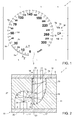
- reference numeral 1 indicates, as a whole, a (partially shown) vehicle instrument panel comprising a dial defined by a plate 2, preferably made of polycarbonate.
- the front surface of the plate 2 has a plurality of graphic areas, some of which are indicated by reference numbers 5a-5i, and which represent markers, graduated scales, numbers, logos, letters, bar graphs, etc. so as to supply the driver with corresponding information on driving and/or the state of the vehicle.
- the portions of the plate 2 that define the above-stated graphic areas are light permeable, i.e. they are substantially transparent so that these graphic areas can be backlit, for example, in the case of night viewing conditions.
- the instrument panel 1 comprises a backlighting device 10, which is designed to light the graphic area 5a and comprises a body 11 made of a light-impermeable material, also known as a light-blocking material, and having a front face 12 on which the plate 2 rests.
- a backlighting device 10 which is designed to light the graphic area 5a and comprises a body 11 made of a light-impermeable material, also known as a light-blocking material, and having a front face 12 on which the plate 2 rests.
- the body 11 comprises a cavity 13, which is empty and has an outlet 14 made on face 12 and closed or engaged by a substantially transparent portion 15 that is part of the plate 2 and defines the graphic area 5a, as explained above.
- the cavity 13 is delimited at the back by a reflective surface 16, which is aligned with the outlet 14 along an axis 17, incident with respect to plate 2 and defining the mean direction along which light exits through the graphic area 5a.
- axis 17 is orthogonal to the plate 2, but could have an angle of incidence other than 90°.
- the cavity 13 is laterally delimited by two surfaces 18 and 19 that face each other, define the outlet 14 and are preferably parallel to axis 17.
- surface 19 extends as a prolongation of surface 16 up to the outlet 14.
- the body 11 is arranged between the plate 2 and a printed circuit board 20 (also denoted by the acronym PCB), which is set apart from the plate 2 and supports at least one LED source 21 designed to emit light that backlights the graphic area 5a.
- the light coming from the LED source 21 is directed towards the plate 2.
- the board 20 is parallel to plate 2; however, if necessary, it can be oriented at a different angle.
- the LED source 21 is considered a point light source.
- the LED source 21 has an optical axis 22 corresponding to the spatial direction in which the emitted light has maximum intensity.
- the optical axis 22 is orthogonal to the board 20 and is set apart from axis 17. The distance between axes 22 and 17 is such as to place the LED source 21 outside the cavity 13, namely laterally with respect to the projection of the graphic area 5a along axis 17.
- optical axis 22 is substantially parallel to axis 17.
- the body 11 comprises a cavity 25, which houses the LED source 21, communicating with cavity 13 through an aperture 26 and is frontally delimited by a reflective surface 27 of the body 11.
- Surface 27 directly faces the LED source 21 along optical axis 22, i.e. without the interposition of other elements.
- the upper border of the aperture 26 is indicated by reference numeral 29 and is defined by an edge that joins surfaces 27 and 18.
- the position of the edge 29 and, consequently, the extension of surface 27 are such as to prevent light rays going directly from the LED source 21 to the outlet 14. In other words, the light rays from the LED source 21 that pass through the aperture 26 only strike surfaces 16 and 19.
- the section plane in Figure 2 is a plane P ( Figure 3 ) on which axes 22 and 17 lie.
- the trace of surface 16 on the section plane P approximates to a parabolic arc.
- the term "approximate" means that the trace of surface 16 on the plane P coincides with a parabolic arc if the possible presence of expedients aimed at diffusing the light rays reflected from surface 13 is excluded.
- these expedients could be defined by the fact that the surface 16 is coarse (i.e. it is rough, satin finished or treated to diffuse the light), or that surface 16 is polished, but defined by prisms, or more in general by protuberances, which are indicated by reference numeral 30 in Figures 5 and 6 and protrude with respect to an ideal design surface.
- the prisms or protuberances 30 are defined by small convex-shaped humps.
- the above-mentioned ideal design surface (which obviously coincides with surface 16 in the absence of coarseness, prisms, etc.) is a sector of an elliptical paraboloid.
- the trace of surface 27 preferably comprises an elliptical arc.
- the parabolic arc defined by the trace of surface 16 and the elliptical arc defined by the trace of surface 27 have a common focus F.
- the light rays reflected by surface 27 all tend to be concentrated on focus F to optimize lighting uniformity on the graphic area 5a.
- the second focus of the elliptical arc lies on axis 22.
- surface 27 is a cylindrical surface that has a generatrix that is at least partially elliptic and a directrix line L that is orthogonal to section plane P.
- the directrix line L is slightly curved so as to define an arc.
- the graphic area 5a is elongated along a straight or curved direction 31, which in the specific case is parallel to the directrix line L.
- the device 10 is constituted by a plurality of units or cells 32, which are substantially equal to each other, are arranged beneath the graphic area 5a and are positioned side by side along direction 31.
- each unit or cell 32 comprises a respective LED source 21, a respective cavity 13 and a respective cavity 25, which have been described above.
- the cavities 13 of the cells 32 communicate with each other along direction 31 through passages 35 defined at the front by plate 2 and at the back by respective edges or borders, which join adjacent surfaces 16.
- the cavities 25 of the cells 32 are instead preferably isolated from each other by separators 36.
- Figures 7 to 9 regard possible variants of the device 10, the components of which are indicated, where possible, by the same reference numerals used in Figure 2 . Even if these solutions are not optimal with respect to that in Figure 2 , it is possible to simplify the design and manufacture of the body 11 and still achieve a sufficient level of lighting uniformity through the graphic area 5a.
- the trace of surface 16 approximates to a straight line (in which surface 16 is defined by a plane or a conical surface).
- the trace of surface 16 is a concave curve, but without a focus or having a focus that does not coincide with that of surface 27.
- surface 27 is defined by a plurality of planes.
- the LED source 21 in the device 10 is not aligned the graphic area 5a, but is outside of cavity 13, while the body 11 is shaped so as to reflect the light from cavity 25 to cavity 13, and so the light does not arrive directly to the graphic area 5a.
- the reflection and possible diffusion of the light enables making the lighting of the graphic area 5a uniform.
- surface 27 is such as to shield the graphic area 5a from direct light emission and, at the same time, collect most of the emitted light and direct it to cavity 13.
- surface 16 is such as to, in turn, 'collect' the light rays in an optimal manner and direct them uniformly to the graphic area 5a.
- the paraboloid shape enables making the lighting uniform in every cell 32, also along direction 31 and not just in section plane P.
- a further contribution to making the lighting uniform is supplied by possible expedients (superficial roughness, polished prisms, etc. for surface 16) provided to diffuse the light that is reflected.
- expedients artificial roughness, polished prisms, etc. for surface 16
- a lighting uniformity of at least 80% or thereabouts can be obtained.
- the shapes of surfaces 16 could be different from those indicated by way of example; and/or the cavities 25 of the cells 32 could communicate with each other; and/or the device 10 could have a single cell 32, or a plurality of cells 32 separated from each other, depending on the characteristics of the graphic area to be backlit.
Applications Claiming Priority (1)
| Application Number | Priority Date | Filing Date | Title |
|---|---|---|---|
| ITTO20140244 | 2014-03-24 |
Publications (2)
| Publication Number | Publication Date |
|---|---|
| EP2924486A1 true EP2924486A1 (de) | 2015-09-30 |
| EP2924486B1 EP2924486B1 (de) | 2016-07-27 |
Family
ID=51033400
Family Applications (1)
| Application Number | Title | Priority Date | Filing Date |
|---|---|---|---|
| EP15160650.6A Active EP2924486B1 (de) | 2014-03-24 | 2015-03-24 | Fahrzeugarmaturenbrett mit einer led-rückbeleuchtungsvorrichtung zur beleuchtung eines grafischen bereichs |
Country Status (5)
| Country | Link |
|---|---|
| US (1) | US10017109B2 (de) |
| EP (1) | EP2924486B1 (de) |
| CN (1) | CN104943547B (de) |
| BR (1) | BR102015006373B1 (de) |
| MX (1) | MX341222B (de) |
Cited By (3)
| Publication number | Priority date | Publication date | Assignee | Title |
|---|---|---|---|---|
| WO2019073105A1 (en) * | 2017-10-10 | 2019-04-18 | Herrmans Oy Ab | WORK LAMP |
| WO2020064590A1 (fr) * | 2018-09-27 | 2020-04-02 | Valeo Vision | Système optique pour éclairage intérieur d'un véhicule |
| IT201800009758A1 (it) | 2018-10-24 | 2020-04-24 | Magneti Marelli Spa | Quadro strumenti provvisto di led di retro-illuminazione, in particolare per un veicolo |
Families Citing this family (13)
| Publication number | Priority date | Publication date | Assignee | Title |
|---|---|---|---|---|
| EP2920019B1 (de) * | 2012-11-13 | 2020-08-12 | Shanghai Yanfeng Jinqiao Automotive Trim Systems Co., Ltd. | Beleuchtete fahrzeuginnenausstattungskomponente |
| JP6597228B2 (ja) * | 2015-11-27 | 2019-10-30 | 日本精機株式会社 | 表示装置 |
| KR101798518B1 (ko) * | 2015-12-09 | 2017-12-12 | 현대자동차주식회사 | 차량용 입체 조명 계기판 |
| AT519119B1 (de) * | 2016-11-22 | 2018-04-15 | Zkw Group Gmbh | Beleuchtungseinrichtung eines kraftfahrzeugscheinwerfers |
| US10890468B2 (en) | 2017-02-02 | 2021-01-12 | Rebo Lighting & Electronics, Llc | Light ring assembly and method of using the same |
| DE102017208999A1 (de) * | 2017-05-29 | 2018-11-29 | Volkswagen Aktiengesellschaft | Beleuchtungsvorrichtung zur Beleuchtung des Innenraums eines Kraftfahrzeugs |
| JP2019039729A (ja) * | 2017-08-24 | 2019-03-14 | 日本精機株式会社 | 計器装置 |
| US10914430B2 (en) * | 2017-12-31 | 2021-02-09 | Google Llc | Smart-home device light rings with lens spacing for uniform output |
| CN110293904B (zh) * | 2018-03-23 | 2023-02-21 | 比亚迪半导体股份有限公司 | 一种换挡发光面板及车辆 |
| CN110543002A (zh) * | 2018-05-29 | 2019-12-06 | 黄太清 | 空腔式面聚焦导波器 |
| DE102018114017A1 (de) * | 2018-06-12 | 2019-12-12 | Dr. Schneider Kunststoffwerke Gmbh | Reflektoranordnung und beleuchtbare Baugruppe |
| CN108819835A (zh) * | 2018-08-07 | 2018-11-16 | 延锋伟世通电子科技(上海)有限公司 | 一种仪表氛围光照明装置 |
| CN112325187A (zh) * | 2020-10-10 | 2021-02-05 | 科博达技术股份有限公司 | 导光式照明装饰装置 |
Citations (5)
| Publication number | Priority date | Publication date | Assignee | Title |
|---|---|---|---|---|
| JPH09152360A (ja) * | 1995-11-30 | 1997-06-10 | Toyoda Gosei Co Ltd | 車両用メータ |
| EP1182395A2 (de) * | 2000-08-25 | 2002-02-27 | Stanley Electric Co., Ltd. | LED-Beleuchtungseinrichtung für Fahrzeug |
| US20060087860A1 (en) * | 2004-10-27 | 2006-04-27 | Koito Manufacturing Co., Ltd. | Vehicle illumination lamp |
| EP2119958A1 (de) * | 2008-05-14 | 2009-11-18 | Ichikoh Industries, Ltd. | Lampe für ein Fahrzeug |
| JP2010276592A (ja) * | 2009-04-28 | 2010-12-09 | Nippon Seiki Co Ltd | 計器の照明装置 |
Family Cites Families (4)
| Publication number | Priority date | Publication date | Assignee | Title |
|---|---|---|---|---|
| DE60036073T2 (de) * | 1999-09-29 | 2008-05-15 | Nippon Seiki Co. Ltd., Nagaoka | Instrument |
| US7763205B2 (en) * | 2004-10-22 | 2010-07-27 | Ceradyne, Inc. | Continuous process for fabricating reaction bonded silicon nitride articles |
| CN101146690B (zh) * | 2005-01-07 | 2012-01-04 | 约翰逊控制技术公司 | 仪表组 |
| JP5067639B2 (ja) * | 2009-04-28 | 2012-11-07 | 日本精機株式会社 | 計器照明装置 |
-
2015
- 2015-03-20 MX MX2015003625A patent/MX341222B/es active IP Right Grant
- 2015-03-23 BR BR102015006373-3A patent/BR102015006373B1/pt active IP Right Grant
- 2015-03-24 CN CN201510131341.7A patent/CN104943547B/zh active Active
- 2015-03-24 US US14/666,477 patent/US10017109B2/en active Active
- 2015-03-24 EP EP15160650.6A patent/EP2924486B1/de active Active
Patent Citations (5)
| Publication number | Priority date | Publication date | Assignee | Title |
|---|---|---|---|---|
| JPH09152360A (ja) * | 1995-11-30 | 1997-06-10 | Toyoda Gosei Co Ltd | 車両用メータ |
| EP1182395A2 (de) * | 2000-08-25 | 2002-02-27 | Stanley Electric Co., Ltd. | LED-Beleuchtungseinrichtung für Fahrzeug |
| US20060087860A1 (en) * | 2004-10-27 | 2006-04-27 | Koito Manufacturing Co., Ltd. | Vehicle illumination lamp |
| EP2119958A1 (de) * | 2008-05-14 | 2009-11-18 | Ichikoh Industries, Ltd. | Lampe für ein Fahrzeug |
| JP2010276592A (ja) * | 2009-04-28 | 2010-12-09 | Nippon Seiki Co Ltd | 計器の照明装置 |
Cited By (7)
| Publication number | Priority date | Publication date | Assignee | Title |
|---|---|---|---|---|
| WO2019073105A1 (en) * | 2017-10-10 | 2019-04-18 | Herrmans Oy Ab | WORK LAMP |
| EP3695162A1 (de) * | 2017-10-10 | 2020-08-19 | Nordic Lights Ltd. | Arbeitsleuchte |
| US11162660B2 (en) | 2017-10-10 | 2021-11-02 | Nordic Lights Ltd. | Working light |
| WO2020064590A1 (fr) * | 2018-09-27 | 2020-04-02 | Valeo Vision | Système optique pour éclairage intérieur d'un véhicule |
| FR3086732A1 (fr) * | 2018-09-27 | 2020-04-03 | Valeo Vision | Systeme optique pour eclairage interieur d’un vehicule |
| US11433807B2 (en) | 2018-09-27 | 2022-09-06 | Valeo Vision | Optical system for interior lighting of a vehicle |
| IT201800009758A1 (it) | 2018-10-24 | 2020-04-24 | Magneti Marelli Spa | Quadro strumenti provvisto di led di retro-illuminazione, in particolare per un veicolo |
Also Published As
| Publication number | Publication date |
|---|---|
| EP2924486B1 (de) | 2016-07-27 |
| BR102015006373B1 (pt) | 2021-12-21 |
| CN104943547A (zh) | 2015-09-30 |
| MX341222B (es) | 2016-08-11 |
| MX2015003625A (es) | 2015-09-23 |
| US20150266419A1 (en) | 2015-09-24 |
| US10017109B2 (en) | 2018-07-10 |
| CN104943547B (zh) | 2019-05-07 |
| BR102015006373A2 (pt) | 2015-12-15 |
Similar Documents
| Publication | Publication Date | Title |
|---|---|---|
| EP2924486B1 (de) | Fahrzeugarmaturenbrett mit einer led-rückbeleuchtungsvorrichtung zur beleuchtung eines grafischen bereichs | |
| EP2725291B1 (de) | Gekrümmte Anzeigevorrichtung | |
| US8368842B2 (en) | Surface light source device and LCD unit | |
| CN108351085B (zh) | 用于车辆的紧凑型照明和/或信号装置 | |
| US20150277027A1 (en) | Vehicular lamp | |
| US20190170317A1 (en) | Light device, especially signal lamp, for motor vehicles | |
| JP2014007014A (ja) | 車両用灯具 | |
| KR102266373B1 (ko) | 차량용 광 가이드를 구비한 조명 및/또는 신호 시스템 | |
| JP6609135B2 (ja) | 車両用リアコンビネーションランプ | |
| EP3604908A1 (de) | Rückbeleuchtungseinheit | |
| TW201508357A (zh) | 單面發光式之透明導光板,及使用該導光板之面發光裝置 | |
| KR102467552B1 (ko) | 자동차 계기판용 글로우 링 | |
| US20160131322A1 (en) | Composite Lamp | |
| US20090225531A1 (en) | Night vision imaging system (NVIS) compliant backlight | |
| JP2012182017A (ja) | 照明装置 | |
| JP2010149762A (ja) | 照明装置 | |
| CN100422814C (zh) | 背光模块 | |
| JP4737337B2 (ja) | 照明装置 | |
| JP2018026192A (ja) | 車両用灯具 | |
| CN216521420U (zh) | 一种光导光幕组合后位置灯及汽车 | |
| CN104633533A (zh) | 背光模块 | |
| JP4548677B2 (ja) | 照明装置 | |
| TWI522695B (zh) | Side light type light emitting module structure | |
| CN109506199B (zh) | 产生均匀照射的小厚度照明装置 | |
| JP3889958B2 (ja) | 面発光体および液晶表示装置 |
Legal Events
| Date | Code | Title | Description |
|---|---|---|---|
| PUAI | Public reference made under article 153(3) epc to a published international application that has entered the european phase |
Free format text: ORIGINAL CODE: 0009012 |
|
| AK | Designated contracting states |
Kind code of ref document: A1 Designated state(s): AL AT BE BG CH CY CZ DE DK EE ES FI FR GB GR HR HU IE IS IT LI LT LU LV MC MK MT NL NO PL PT RO RS SE SI SK SM TR |
|
| AX | Request for extension of the european patent |
Extension state: BA ME |
|
| 17P | Request for examination filed |
Effective date: 20151112 |
|
| REG | Reference to a national code |
Ref country code: DE Ref legal event code: R079 Ref document number: 602015000154 Country of ref document: DE Free format text: PREVIOUS MAIN CLASS: G02B0019000000 Ipc: B60K0035000000 |
|
| GRAP | Despatch of communication of intention to grant a patent |
Free format text: ORIGINAL CODE: EPIDOSNIGR1 |
|
| RIC1 | Information provided on ipc code assigned before grant |
Ipc: G02B 19/00 20060101ALI20160112BHEP Ipc: G01D 11/28 20060101ALI20160112BHEP Ipc: B60Q 3/04 20060101ALI20160112BHEP Ipc: B60K 35/00 20060101AFI20160112BHEP |
|
| INTG | Intention to grant announced |
Effective date: 20160209 |
|
| GRAR | Information related to intention to grant a patent recorded |
Free format text: ORIGINAL CODE: EPIDOSNIGR71 |
|
| GRAS | Grant fee paid |
Free format text: ORIGINAL CODE: EPIDOSNIGR3 |
|
| GRAA | (expected) grant |
Free format text: ORIGINAL CODE: 0009210 |
|
| AK | Designated contracting states |
Kind code of ref document: B1 Designated state(s): AL AT BE BG CH CY CZ DE DK EE ES FI FR GB GR HR HU IE IS IT LI LT LU LV MC MK MT NL NO PL PT RO RS SE SI SK SM TR |
|
| INTG | Intention to grant announced |
Effective date: 20160622 |
|
| REG | Reference to a national code |
Ref country code: GB Ref legal event code: FG4D |
|
| REG | Reference to a national code |
Ref country code: CH Ref legal event code: EP |
|
| REG | Reference to a national code |
Ref country code: AT Ref legal event code: REF Ref document number: 815497 Country of ref document: AT Kind code of ref document: T Effective date: 20160815 |
|
| REG | Reference to a national code |
Ref country code: IE Ref legal event code: FG4D |
|
| REG | Reference to a national code |
Ref country code: DE Ref legal event code: R096 Ref document number: 602015000154 Country of ref document: DE |
|
| REG | Reference to a national code |
Ref country code: LT Ref legal event code: MG4D |
|
| REG | Reference to a national code |
Ref country code: NL Ref legal event code: MP Effective date: 20160727 |
|
| REG | Reference to a national code |
Ref country code: AT Ref legal event code: MK05 Ref document number: 815497 Country of ref document: AT Kind code of ref document: T Effective date: 20160727 |
|
| PG25 | Lapsed in a contracting state [announced via postgrant information from national office to epo] |
Ref country code: HR Free format text: LAPSE BECAUSE OF FAILURE TO SUBMIT A TRANSLATION OF THE DESCRIPTION OR TO PAY THE FEE WITHIN THE PRESCRIBED TIME-LIMIT Effective date: 20160727 Ref country code: FI Free format text: LAPSE BECAUSE OF FAILURE TO SUBMIT A TRANSLATION OF THE DESCRIPTION OR TO PAY THE FEE WITHIN THE PRESCRIBED TIME-LIMIT Effective date: 20160727 Ref country code: NL Free format text: LAPSE BECAUSE OF FAILURE TO SUBMIT A TRANSLATION OF THE DESCRIPTION OR TO PAY THE FEE WITHIN THE PRESCRIBED TIME-LIMIT Effective date: 20160727 Ref country code: RS Free format text: LAPSE BECAUSE OF FAILURE TO SUBMIT A TRANSLATION OF THE DESCRIPTION OR TO PAY THE FEE WITHIN THE PRESCRIBED TIME-LIMIT Effective date: 20160727 Ref country code: LT Free format text: LAPSE BECAUSE OF FAILURE TO SUBMIT A TRANSLATION OF THE DESCRIPTION OR TO PAY THE FEE WITHIN THE PRESCRIBED TIME-LIMIT Effective date: 20160727 Ref country code: IS Free format text: LAPSE BECAUSE OF FAILURE TO SUBMIT A TRANSLATION OF THE DESCRIPTION OR TO PAY THE FEE WITHIN THE PRESCRIBED TIME-LIMIT Effective date: 20161127 Ref country code: NO Free format text: LAPSE BECAUSE OF FAILURE TO SUBMIT A TRANSLATION OF THE DESCRIPTION OR TO PAY THE FEE WITHIN THE PRESCRIBED TIME-LIMIT Effective date: 20161027 |
|
| REG | Reference to a national code |
Ref country code: FR Ref legal event code: PLFP Year of fee payment: 3 |
|
| PG25 | Lapsed in a contracting state [announced via postgrant information from national office to epo] |
Ref country code: AT Free format text: LAPSE BECAUSE OF FAILURE TO SUBMIT A TRANSLATION OF THE DESCRIPTION OR TO PAY THE FEE WITHIN THE PRESCRIBED TIME-LIMIT Effective date: 20160727 Ref country code: PL Free format text: LAPSE BECAUSE OF FAILURE TO SUBMIT A TRANSLATION OF THE DESCRIPTION OR TO PAY THE FEE WITHIN THE PRESCRIBED TIME-LIMIT Effective date: 20160727 Ref country code: BE Free format text: LAPSE BECAUSE OF FAILURE TO SUBMIT A TRANSLATION OF THE DESCRIPTION OR TO PAY THE FEE WITHIN THE PRESCRIBED TIME-LIMIT Effective date: 20160727 Ref country code: GR Free format text: LAPSE BECAUSE OF FAILURE TO SUBMIT A TRANSLATION OF THE DESCRIPTION OR TO PAY THE FEE WITHIN THE PRESCRIBED TIME-LIMIT Effective date: 20161028 Ref country code: ES Free format text: LAPSE BECAUSE OF FAILURE TO SUBMIT A TRANSLATION OF THE DESCRIPTION OR TO PAY THE FEE WITHIN THE PRESCRIBED TIME-LIMIT Effective date: 20160727 Ref country code: LV Free format text: LAPSE BECAUSE OF FAILURE TO SUBMIT A TRANSLATION OF THE DESCRIPTION OR TO PAY THE FEE WITHIN THE PRESCRIBED TIME-LIMIT Effective date: 20160727 Ref country code: PT Free format text: LAPSE BECAUSE OF FAILURE TO SUBMIT A TRANSLATION OF THE DESCRIPTION OR TO PAY THE FEE WITHIN THE PRESCRIBED TIME-LIMIT Effective date: 20161128 Ref country code: SE Free format text: LAPSE BECAUSE OF FAILURE TO SUBMIT A TRANSLATION OF THE DESCRIPTION OR TO PAY THE FEE WITHIN THE PRESCRIBED TIME-LIMIT Effective date: 20160727 |
|
| PG25 | Lapsed in a contracting state [announced via postgrant information from national office to epo] |
Ref country code: RO Free format text: LAPSE BECAUSE OF FAILURE TO SUBMIT A TRANSLATION OF THE DESCRIPTION OR TO PAY THE FEE WITHIN THE PRESCRIBED TIME-LIMIT Effective date: 20160727 Ref country code: EE Free format text: LAPSE BECAUSE OF FAILURE TO SUBMIT A TRANSLATION OF THE DESCRIPTION OR TO PAY THE FEE WITHIN THE PRESCRIBED TIME-LIMIT Effective date: 20160727 |
|
| REG | Reference to a national code |
Ref country code: DE Ref legal event code: R097 Ref document number: 602015000154 Country of ref document: DE |
|
| PG25 | Lapsed in a contracting state [announced via postgrant information from national office to epo] |
Ref country code: BG Free format text: LAPSE BECAUSE OF FAILURE TO SUBMIT A TRANSLATION OF THE DESCRIPTION OR TO PAY THE FEE WITHIN THE PRESCRIBED TIME-LIMIT Effective date: 20161027 Ref country code: DK Free format text: LAPSE BECAUSE OF FAILURE TO SUBMIT A TRANSLATION OF THE DESCRIPTION OR TO PAY THE FEE WITHIN THE PRESCRIBED TIME-LIMIT Effective date: 20160727 Ref country code: SK Free format text: LAPSE BECAUSE OF FAILURE TO SUBMIT A TRANSLATION OF THE DESCRIPTION OR TO PAY THE FEE WITHIN THE PRESCRIBED TIME-LIMIT Effective date: 20160727 Ref country code: SM Free format text: LAPSE BECAUSE OF FAILURE TO SUBMIT A TRANSLATION OF THE DESCRIPTION OR TO PAY THE FEE WITHIN THE PRESCRIBED TIME-LIMIT Effective date: 20160727 Ref country code: CZ Free format text: LAPSE BECAUSE OF FAILURE TO SUBMIT A TRANSLATION OF THE DESCRIPTION OR TO PAY THE FEE WITHIN THE PRESCRIBED TIME-LIMIT Effective date: 20160727 |
|
| PLBE | No opposition filed within time limit |
Free format text: ORIGINAL CODE: 0009261 |
|
| STAA | Information on the status of an ep patent application or granted ep patent |
Free format text: STATUS: NO OPPOSITION FILED WITHIN TIME LIMIT |
|
| 26N | No opposition filed |
Effective date: 20170502 |
|
| PG25 | Lapsed in a contracting state [announced via postgrant information from national office to epo] |
Ref country code: SI Free format text: LAPSE BECAUSE OF FAILURE TO SUBMIT A TRANSLATION OF THE DESCRIPTION OR TO PAY THE FEE WITHIN THE PRESCRIBED TIME-LIMIT Effective date: 20160727 |
|
| PG25 | Lapsed in a contracting state [announced via postgrant information from national office to epo] |
Ref country code: MC Free format text: LAPSE BECAUSE OF FAILURE TO SUBMIT A TRANSLATION OF THE DESCRIPTION OR TO PAY THE FEE WITHIN THE PRESCRIBED TIME-LIMIT Effective date: 20160727 |
|
| REG | Reference to a national code |
Ref country code: IE Ref legal event code: MM4A |
|
| PG25 | Lapsed in a contracting state [announced via postgrant information from national office to epo] |
Ref country code: LU Free format text: LAPSE BECAUSE OF NON-PAYMENT OF DUE FEES Effective date: 20170324 |
|
| REG | Reference to a national code |
Ref country code: FR Ref legal event code: PLFP Year of fee payment: 4 |
|
| PG25 | Lapsed in a contracting state [announced via postgrant information from national office to epo] |
Ref country code: IE Free format text: LAPSE BECAUSE OF NON-PAYMENT OF DUE FEES Effective date: 20170324 |
|
| PG25 | Lapsed in a contracting state [announced via postgrant information from national office to epo] |
Ref country code: MT Free format text: LAPSE BECAUSE OF NON-PAYMENT OF DUE FEES Effective date: 20170324 |
|
| PG25 | Lapsed in a contracting state [announced via postgrant information from national office to epo] |
Ref country code: AL Free format text: LAPSE BECAUSE OF FAILURE TO SUBMIT A TRANSLATION OF THE DESCRIPTION OR TO PAY THE FEE WITHIN THE PRESCRIBED TIME-LIMIT Effective date: 20160727 |
|
| REG | Reference to a national code |
Ref country code: CH Ref legal event code: PL |
|
| PG25 | Lapsed in a contracting state [announced via postgrant information from national office to epo] |
Ref country code: LI Free format text: LAPSE BECAUSE OF NON-PAYMENT OF DUE FEES Effective date: 20180331 Ref country code: CH Free format text: LAPSE BECAUSE OF NON-PAYMENT OF DUE FEES Effective date: 20180331 |
|
| PG25 | Lapsed in a contracting state [announced via postgrant information from national office to epo] |
Ref country code: HU Free format text: LAPSE BECAUSE OF FAILURE TO SUBMIT A TRANSLATION OF THE DESCRIPTION OR TO PAY THE FEE WITHIN THE PRESCRIBED TIME-LIMIT; INVALID AB INITIO Effective date: 20150324 |
|
| PG25 | Lapsed in a contracting state [announced via postgrant information from national office to epo] |
Ref country code: CY Free format text: LAPSE BECAUSE OF FAILURE TO SUBMIT A TRANSLATION OF THE DESCRIPTION OR TO PAY THE FEE WITHIN THE PRESCRIBED TIME-LIMIT Effective date: 20160727 |
|
| GBPC | Gb: european patent ceased through non-payment of renewal fee |
Effective date: 20190324 |
|
| PG25 | Lapsed in a contracting state [announced via postgrant information from national office to epo] |
Ref country code: MK Free format text: LAPSE BECAUSE OF FAILURE TO SUBMIT A TRANSLATION OF THE DESCRIPTION OR TO PAY THE FEE WITHIN THE PRESCRIBED TIME-LIMIT Effective date: 20160727 |
|
| PG25 | Lapsed in a contracting state [announced via postgrant information from national office to epo] |
Ref country code: GB Free format text: LAPSE BECAUSE OF NON-PAYMENT OF DUE FEES Effective date: 20190324 |
|
| PGFP | Annual fee paid to national office [announced via postgrant information from national office to epo] |
Ref country code: FR Payment date: 20230222 Year of fee payment: 9 |
|
| PGFP | Annual fee paid to national office [announced via postgrant information from national office to epo] |
Ref country code: TR Payment date: 20230227 Year of fee payment: 9 Ref country code: IT Payment date: 20230221 Year of fee payment: 9 Ref country code: DE Payment date: 20230221 Year of fee payment: 9 |
|
| PGFP | Annual fee paid to national office [announced via postgrant information from national office to epo] |
Ref country code: DE Payment date: 20240220 Year of fee payment: 10 |