EP2923914A1 - Hohlschwellenweichenstellsystem mit Nockenstangenhubbegrenzung - Google Patents
Hohlschwellenweichenstellsystem mit Nockenstangenhubbegrenzung Download PDFInfo
- Publication number
- EP2923914A1 EP2923914A1 EP14161589.8A EP14161589A EP2923914A1 EP 2923914 A1 EP2923914 A1 EP 2923914A1 EP 14161589 A EP14161589 A EP 14161589A EP 2923914 A1 EP2923914 A1 EP 2923914A1
- Authority
- EP
- European Patent Office
- Prior art keywords
- switch
- center
- attack
- cam
- stop element
- Prior art date
- Legal status (The legal status is an assumption and is not a legal conclusion. Google has not performed a legal analysis and makes no representation as to the accuracy of the status listed.)
- Granted
Links
Images


Classifications
-
- B—PERFORMING OPERATIONS; TRANSPORTING
- B61—RAILWAYS
- B61L—GUIDING RAILWAY TRAFFIC; ENSURING THE SAFETY OF RAILWAY TRAFFIC
- B61L5/00—Local operating mechanisms for points or track-mounted scotch-blocks; Visible or audible signals; Local operating mechanisms for visible or audible signals
- B61L5/02—Mechanical devices for operating points or scotch-blocks, e.g. local manual control
-
- B—PERFORMING OPERATIONS; TRANSPORTING
- B61—RAILWAYS
- B61L—GUIDING RAILWAY TRAFFIC; ENSURING THE SAFETY OF RAILWAY TRAFFIC
- B61L5/00—Local operating mechanisms for points or track-mounted scotch-blocks; Visible or audible signals; Local operating mechanisms for visible or audible signals
- B61L5/10—Locking mechanisms for points; Means for indicating the setting of points
Definitions
- the present invention relates to a switch system with a built-in hollow sleeper switch lock, in particular latch closure.
- a point setting system such as the latch closure CKA12 from Siemens Switzerland AG, typically has at least one drive rod which transmits the longitudinal movement generated by a point machine to the switch tongues.
- switch blades are in turn usually connected indirectly with one cam rod. Since most railway administrations urgently require electrical isolation between the left and right switch blade and further insulation to the drive rod, an isolated arranged attacking part is provided, which imparts a force transmission from the drive rod to the cam bar.
- a hollow sleeper space is very limited. As a result, the accessibility to the components is much more difficult.
- Such a Weichenstellsystem is in the European patent application EP 1 195 310 A1 disclosed.
- An integrated into a hollow sleeper latch closure is also from the German patent application DE 43 15 200 A1 known.
- This point control system is today sold under the name "Switchguard ITS700” by Siemens AG.
- This point system can drive in the "wrong" direction up to a speed of around 40 km / h and be cut open or driven up.
- the retaining clutch is usually triggered mechanically in the point mechanism, whereby the longitudinal position of the drive rod changes. Sometimes this means that the point machine can no longer reach the end position.
- the structural design of the retaining clutch it may be that this can not be reset automatically, for example by reversing the switch again. For this reason, a railway employee currently has to snap the slide rod of the latch closure back into the retaining coupling on site and by hand.
- the present invention is therefore an object of the invention to provide a points system, which makes it possible, even after an operational Weichenetzschung take the switch from the interlocking again in operation, without the manual use of an employee at the point where the switch would be required.
- two opposing stop elements are arranged on the central attack, which cooperate with a central strut arranged centrally relative to the two stop elements.
- a centrally arranged stop element is arranged on the center attack, which cooperates with two diametrically opposed center struts. In an adjustment of the switch therefore proposes upon reaching the maximum predefined stroke, the central stop element on one of the two center struts.
- center strut is fastened on both sides by means of integrated damping elements at the upper edge of the hollow sleeper.
- center attack may also be alternatively provided a simple flat iron that holds the cam bars together and has a side attack on the push rod of the adjustment.
- FIG. 1 shows a schematic view of connected to a central attack 2 cam rods 5a, 5b of a switch system not shown here, such as a latch closure type CKA 12 from the house of Siemens Switzerland AG. Deviating from the type CKA 12 here are the two integrally formed on the center attack 2 stop elements 3a and 3b, which constitute an essential part of the present invention.
- a latch closure of the type CKA12 is, for example, in the above-mentioned German patent application DE 43 15 200 A1 disclosed.
- the indirectly each with a switch tongue (in Fig. 1 not shown) connected cam rods 5a, 5b are with screw - each formed from connecting screw 15 and connecting nut 16 - coupled via pressure plates 24 and insulating 14 with a so-called. Attacking flange.
- This attack flange is referred to below in this embodiment as the center attack 2.
- the center attack 2 is symmetrical with respect to the track axis and has a significantly larger cross section in the middle part. In the central part of a continuous locking slot 4 is milled, which has two plane-parallel surfaces.
- an engaging piece 1 is connected to the center attack 2, wherein in the dissolved state, the engaging piece 1 is displaceable relative to the center attack 2.
- a bearing pin 11 is guided in the slot S1 by a drive rod (in Fig. 1 not shown) is guided and so a power transmission of drive rod on the attacking piece 1, the center attack 2 and the cam rods 5a, 5b allows for the switch blades.
- a locking plate 12 is provided, which in this embodiment has openings which are slipped over the hexagonal heads of the locking screw 13 and on both sides over the central part of the central attack 2.
- such an opening is through twice punching a hexagon formed so that before the second punching a rotation of 30 ° of the tool is made relative to the locking plate.
- the tightening of the screws can be carried out with a resolution of about 30 ° and a reliable securing of the locking screws 13 against a spontaneous release can be achieved.
- connection of the two cam bars can also be realized by means of a simple connecting lug.
- the connection to the drive rod takes place in this arrangement by means of a coupling, designed as a side attack, at the outer end of a cam rod.
- the two stop elements 3a and 3b are integrally formed on the lateral arms of the center attack 2, whose function with respect to the FIG. 2 be explained.
- the FIG. 2 shows a schematic view of the connected to the center attack 2 cam rods 5a, 5b according to FIG. 1 in the installed in a hollow sleeper 20 state with a first embodiment for the interaction of the stop elements 3a, 3b and the hollow sleeper 20 bridging center strut 22.
- the center strut 22 is centrally above the open-topped hollow sleeper 20, on horizontal flanges after Upwardly extending cheeks of the hollow sleeper, bolted with damping elements.
- the details of the installation of the latch closure in the hollow sleeper 20 is again to the German patent application DE 43 15 200 A1 directed.
- the drive rod (not shown) coupled to the center attack 2 can move the cam bars 5a, 5b in both directions only up to the abutment of the respective stop element 3a, 3b on the center stay 22.
- This stroke limit for the movement of the cam bars 5a, 5b forms the requirement for the return of a detent caused by a cutting of the switch.
- the retaining coupling can follow the associated lock slider and engage properly, which would not be possible without this stroke limitation of the cam rods 5a, 5b.
- the stop elements 3a, 3b are integrally formed on the lateral arms of the central attack 2.
- the abutment elements 3a, 3b could also be arranged on the pressure plates 24, which are used for connecting the center attack 2 with cam bars 5a, 5b, as in FIG. 2 is shown in a perspective view with a viewing direction obliquely from above into the upwardly open hollow threshold.
- FIG. 3 shows from the same perspective as the FIG. 2 a schematic view of the associated with the central attack 2 cam rods 5a, 5b according to one opposite FIG. 2 slightly modified variant in the installed in a hollow sleeper 20 state with a second embodiment for the interaction of a stop element 3c and two the hollow sleeper bridging center struts 22a, 22b.
- the stop element 3 c is here formed centrally on the center attack 2.
- the two lateral stops 3a, 3b according to the FIGS. 1 and 2 omitted in this variant.
- two oppositely disposed center struts 22a, 22b are provided, which here are mounted in one piece in the form of a ring element 26 on the horizontal flanges of the rising cheeks of the hollow sleeper 20.
- FIG. 4 shows a lateral schematic view of the storage of the center strut 22 including the damping elements 28, which absorb the kinetic energy at a fraction at least partially.
Landscapes
- Engineering & Computer Science (AREA)
- Mechanical Engineering (AREA)
- Train Traffic Observation, Control, And Security (AREA)
- Fluid-Damping Devices (AREA)
Abstract
Description
- Die vorliegende Erfindung betrifft ein Weichenstellsystem mit einem in eine Hohlschwelle eingebauten Weichenverschluss, insbesondere Klinkenverschluss.
- Weichen sind durch Witterungseinflüsse und durch das Befahren durch Züge einer hohen Beanspruchung ausgesetzt. Dadurch können sich bei der Montage vorgenommene Justierungen und Einstellungen verändern. Mit einer Justierung ist insbesondere eine gleichmässige Überdeckung der den Weichenzungen zugeordneten Verschlussklinken sicherzustellen. Im folgenden wird mit dem vorstehend erläuterten Begriff Justierung auch die Einstellung der Symmetrie in einem Weichenstellsystem verstanden.
- Aus der internationalen Patentanmeldung
WO 94/27853 A1 - Ein Weichenstellsystem, wie zum Beispiel der Klinkenverschluss CKA12 der Siemens Schweiz AG, weist typischerweise wenigstens eine Antriebsstange auf, die die von einem Weichenantrieb generierte Längsbewegung zu den Weichenzungen überträgt. Dabei sind Weichenzungen ihrerseits in der Regel indirekt mit je einer Nockenstange verbunden. Da die meisten Eisenbahnverwaltungen zwingend eine elektrische Isolation zwischen linker und rechter Weichenzunge sowie eine weitere Isolation zur Antriebsstange verlangen, ist ein isoliertes angeordnetes Angriffsteil vorgesehen, das eine Kraftübertragung von der Antriebsstange auf die Nockenstange vermittelt. In einer Hohlschwelle sind die Platzverhältnisse sehr begrenzt. Dadurch ist die Zugänglichkeit zu den Komponenten stark erschwert. Ein derartiges Weichenstellsystem ist in der europäischen Patentanmeldung
EP 1 195 310 A1 offenbart. Ein in eine Hohlschwelle integrierter Klinkenverschluss ist auch aus der deutschen PatentanmeldungDE 43 15 200 A1 bekannt. Dieses Weichenstellsystem wird heute unter dem Namen "Switchguard ITS700" von der Siemens AG vertrieben. Dieses Weichenstellsystem kann bis zu einer Geschwindigkeit von rund 40 km/h in der "falschen" Richtung befahren und dabei aufgeschnitten oder aufgefahren werden. Hierbei wird in der Regel die Festhaltekupplung im Weichenantrieb mechanisch ausgelöst, wodurch sich die Längslage der Antriebsstange verändert. Mitunter hat dies zur Folge, dass der Weichenantrieb keine Endlage mehr erreichen kann. In Abhängigkeit von der konstruktiven Ausführung der Festhaltekupplung kann es sein, dass diese nicht mehr automatisch, beispielweise mittels Reversieren der Weiche, wieder zurückgestellt werden kann. Aus diesem Grund muss momentan noch ein Bahnmitarbeiter die Schieberstange des Klinkenverschlusses vor Ort und von Hand wieder in der Festhaltekupplung einrasten. - Der vorliegenden Erfindung liegt daher die Aufgabe zugrunde, ein Weichenstellsystem anzugeben, das es ermöglicht, auch nach einer betrieblichen Weichenaufschneidung die Weiche vom Stellwerk aus wieder in Betrieb nehmen zu können, ohne dass der händische Einsatz eines Mitarbeiters am Ort der Weiche erforderlich wäre.
- Diese Aufgabe wird erfindungsgemäss durch ein Weichenstellsystem mit einem in eine Hohlschwelle eingebauten Weichenverschluss, insbesondere Klinkenverschluss, gelöst, wobei das Weichenstellsystem u.a. die folgenden erfindungswesentlichen Komponenten umfasst:
- a) zwei mit einem Mittenangriff bzw. Verbindungslasche zusammengehaltene Nockenstangen,
- b) mindestens ein mit dem Mittenangriff bzw. Verbindungslasche verbindbares Anschlagselement;
- c) mindestens eine die nach oben offene Hohlschwelle überbrückende Mittelstrebe, wobei
- d) das mindestens eine Anschlagselement und die mindestens eine Mittelstrebe so zusammenwirken, dass ein Hub der Schieberstange begrenzt wird, indem das Anschlagselement bei Erreichen eines zuvor bestimmten maximalen Verstellhubes der Nockenstangen an der Mittelstrebe anschlägt.
- Auf diese Weise ist es mit dem erfindungsgemässen Weichenstellsystem möglich eine aufgeschnittene Weiche vom Stellwerk aus im Rahmen eines normalen Weichenhubes wieder in den bestimmungsgemässen Betrieb nehmen zu können, ohne dass ein Bahnmitarbeiter vor Ort an der Weiche die Nockenstange in den Verstellmechanismus der Weiche einrasten muss. Das mit dem Zusammenwirken von Anschlagselement und Mittelstrebe entstehende Gegenlager ermöglicht so den Hub der Nockenstange zu begrenzen, sodass der aus dem Stellwerk ausgelöste Weichenhub wieder zum Einrasten der Nockenstange in den Verstellmechanismus der Weiche führt.
- In einer besonders bevorzugten Ausgestaltung der vorliegenden Erfindung kann es vorgesehen sein, dass am Mittenangriff zwei gegenüberliegende Anschlagselemente angeordnet sind, die mit einer zentral relativ zu den beiden Anschlagselementen angeordneten Mittelstrebe zusammenwirken. Bei der Umstellung einer aufgeschnittenen Weiche schlägt daher bei Erreichen des maximalen vordefinierten Hubes eines der Anschlagselemente an der zentralen Mittelstrebe an, sodass die ausgelöste Festhaltekupplung wieder einrasten kann, womit das Weichenstellsystem die Weiche wieder betrieblich umstellen kann.
- In einer hierzu alternativen Ausführungsform der vorliegenden Erfindung kann es vorgesehen sein, dass am Mittenangriff ein zentral angeordnetes Anschlagelement angeordnet ist, das mit zwei diametral gegenüberliegend angeordneten Mittelstreben zusammenwirkt. Bei einer Verstellung der Weiche schlägt daher bei Erreichen des maximalen vordefinierten Hubes das zentrale Anschlagelement an einer der beiden Mittelstreben an.
- Weiter kann es vorgesehen sein, dass die Mittelstrebe mittels integrierter Dämpfungselemente am oberen Rand der Hohlschwelle beidseitig befestigt wird.
- Anstelle des Mittenangriffs kann auch alternativ ein einfaches Flacheisen vorgesehen sein, dass die Nockenstangen zusammenhält und einen Seitenangriff für die Schubstange des Verstellmechanismus aufweist.
- Bevorzugte Ausführungsbeispiel der vorliegenden Erfindung werden nachfolgend anhand der Zeichnung näher erläutert. Dabei zeigen:
- Figur 1
- eine schematische Ansicht von mit einem Mittenangriff verbundenen Nockenstangen eines Weichenstellsystems;
- Figur 2
- eine schematische Ansicht der mit dem Mittenangriff verbundenen Nockenstangen gemäss
Figur 1 im in eine Hohlschwelle eingebauten Zustand mit einer ersten Ausführungsform für das Zusammenwirken von Anschlagelementen und eine die Hohlschwelle überbrückende Mittelstrebe; - Figur 3
- eine schematische Ansicht der mit dem Mittenangriff verbundenen Nockenstangen gemäss einer gegenüber
Figur 1 geringfügig modifizierten Variante im in eine Hohlschwelle eingebauten Zustand mit einer zweiten Ausführungsform für das Zusammenwirken von einem Anschlagelement und zwei die Hohlschwelle überbrückende Mittelstreben; und - Figur 4
- eine schematische Ansicht der Lagerung der Mittelstrebe inklusive der Dämpfungselemente, welche die kinetische Energie bei einer Aufschneidung zumindest teilweise aufnehmen.
-
Figur 1 zeigt eine schematische Ansicht von mit einem Mittenangriff 2 verbundenen Nockenstangen 5a, 5b eines hier nicht weiter dargestellten Weichenstellsystem, wie zum Beispiel eines Klinkenverschlusses der Bauart CKA 12 aus dem Hause der Siemens Schweiz AG. Abweichend gegenüber der Bauart CKA 12 sind hier die beiden an dem Mittenangriff 2 angeformten Anschlagelemente 3a und 3b, die einen wesentlichen Bestandteil der vorliegenden Erfindung darstellen. Ein Klinkenverschluss der Bauart CKA12 ist beispielsweise in der vorstehend schon genannten deutschen PatentanmeldungDE 43 15 200 A1 offenbart. - Die indirekt je mit einer Weichenzunge (in
Fig. 1 nicht dargestellt) verbundenen Nockenstangen 5a, 5b sind mit Schraubverbindungen - gebildet je aus Verbindungsschraube 15 und Verbindungsmutter 16 - über Druckplatten 24 sowie Isolierplatten 14 mit einem sog. Angriffsflansch gekoppelt. Dieser Angriffsflansch wird im Folgenden in dieser Ausführungsform als der Mittenangriff 2 bezeichnet. Der Mittenangriff 2 ist bezüglich der Gleisachse symmetrisch ausgeführt und weist im Mittelteil einen bedeutend grösseren Querschnitt auf. Im Mittelteil ist ein durchgehender Feststellschlitz 4 eingefräst, der zwei planparallele Flächen aufweist. Mit zwei Feststellschrauben 13 ist ein Angriffsstück 1 mit dem Mittenangriff 2 verbunden, wobei im gelösten Zustand das Angriffsstück 1 relativ zum Mittenangriff 2 verschiebbar ist. Durch eine Bohrung 9 oder 10 wird ein Lagerbolzen 11 geführt, der im Schlitz S1 durch eine Antriebsstange (inFig. 1 nicht dargestellt) geführt wird und so eine Kraftübertragung von Antriebsstange über das Angriffsstück 1, den Mittenangriff 2 und die Nockenstangen 5a, 5b zu den Weichenzungen ermöglicht. Um ein Lösen der Feststellschrauben 13 durch Vibrationen zu verhindern, ist ein Sicherungsblech 12 vorgesehen, das in dieser Ausführungsform Öffnungen aufweist, die über die Sechskantköpfe der Feststellschraube 13 und beidseitig über den Mittelteil des Mittenangriffs 2 gestülpt werden. Um eine z.B. mittels Drehmomentschlüssel definierte Verbindung herstellen zu können, ist eine solche Öffnung durch zweimaliges Stanzen eines Sechseckes so gebildet, dass vor dem zweiten Stanzen eine Drehung um 30° des Werkzeugs relativ zum Sicherungsblech vorgenommen wird. Dadurch kann das Anziehen der Schrauben mit einer Auflösung von rund 30° vorgenommen werden und eine zuverlässige Sicherung der Feststellschrauben 13 gegen ein spontanes Lösen erzielt werden. Dadurch, dass die Feststellschrauben 13 von oben her leicht zugänglich sind, kann eine Justierung bei der Erstmontage oder bei der Wartung einer Weiche leicht vorgenommen werden. - In Erweiterung dazu, kann die mechanische Verbindung der zwei Nockenstangen auch mittels einer einfachen Verbindungslasche realisiert werden. Die Verbindung zur Antriebsstange erfolgt bei dieser Anordnung mittels einer Ankopplung, ausgebildet als Seitenangriff, am äusseren Ende einer Nockenstange.
- In vorliegenden Ausführungsbeispiel sind an den seitlichen Auslegern des Mittenangriff 2 die beiden Anschlagelemente 3a und 3b angeformt, deren Funktion mit Bezug auf die
Figur 2 erläutert werden. DieFigur 2 zeigt eine schematische Ansicht der mit dem Mittenangriff 2 verbundenen Nockenstangen 5a, 5b gemässFigur 1 im in eine Hohlschwelle 20 eingebauten Zustand mit einer ersten Ausführungsform für das Zusammenwirken von den Anschlagelementen 3a, 3b und einer die Hohlschwelle 20 überbrückende Mittelstrebe 22. Die Mittelstrebe 22 ist dabei zentral über der nach oben offenen Hohlschwelle 20, und zwar auf waagrechte Flanschen der nach oben verlaufenden Wangen der Hohlschwelle, mit Dämpfungselementen verschraubt. Zu den Details des Einbaus des Klinkenverschlusses in die Hohlschwelle 20 wird nochmals auf die deutsche PatentanmeldungDE 43 15 200 A1 verwiesen. - Im Betrieb kann die am Mittenangriff 2 ankoppelnde Antriebstange (nicht dargestellt) die Nockenstangen 5a, 5b in beiden Richtung nur bis zum Anschlagen des jeweiligen Anschlagelements 3a, 3b an der Mittelstrebe 22 bewegen. Diese Hubbegrenzung für die Bewegung der Nockenstangen 5a, 5b bildet die Voraussetzung für das Zurückstellen einer infolge eines Aufschneidens der Weiche ausgelösten Festhaltekupplung. Beim vom nun mehr zentral vom Stellwerk auslösbaren Reversiervorgang kann die Festhaltekupplung dem zugehörigen Stellschieber nachfahren und ordnungsgemäss einrasten, was ohne diese Hubbegrenzung der Nockenstangen 5a, 5b nicht möglich wäre.
- In der in
Figur 1 gezeigten Variante sind die Anschlagelemente 3a, 3b an den seitlichen Auslegern des Mittenangriffs 2 angeformt. Die Anschlagelemente 3a, 3b könnten aber auch an den Druckplatten 24, die zur Verbindung des Mittenangriffs 2 mit Nockenstangen 5a, 5b verwendet werden, angeordnet werden, so wie dies inFigur 2 in perspektivischer Darstellung mit einer Blickrichtung von schräg oben in die nach oben offene Hohlschwelle dargestellt ist. -
Figur 3 zeigt aus derselben Perspektive wie dieFigur 2 eine schematische Ansicht der mit dem Mittenangriff 2 verbundenen Nockenstangen 5a, 5b gemäss einer gegenüberFigur 2 geringfügig modifizierten Variante im in eine Hohlschwelle 20 eingebauten Zustand mit einer zweiten Ausführungsform für das Zusammenwirken von einem Anschlagelement 3c und zwei die Hohlschwelle überbrückende Mittelstreben 22a, 22b. Das Anschlagelement 3c ist hier zentral am Mittenangriff 2 angeformt. Die beiden seitlichen Anschläge 3a, 3b gemäss denFiguren 1 und2 entfallen bei dieser Variante. Dafür sind zwei gegenüberliegend angeordnete Mittelstreben 22a, 22b vorgesehen, die hier vorliegend einteilig in Form eines Ringelements 26 auf den waagrechten Flanschen der aufsteigenden Wangen der Hohlschwelle 20 montiert sind. Auch hier ist leicht nachvollziehbar, wie das zentral angeordnete Anschlagelement 3c mit den beiden seitlich angeordneten Mittelstreben 22a und 22b zur Hubbegrenzung der Nockenstangen 5a, 5b zusammenwirken. -
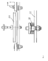
Figur 4 zeigt eine seitliche schematische Ansicht der Lagerung der Mittelstrebe 22 inklusive der Dämpfungselemente 28, welche die kinetische Energie bei einer Aufschneidung zumindest teilweise aufnehmen.
Claims (3)
- Weichenstellsystem mit einem in eine Hohlschwelle (20) eingebauten Weichenverschluss, insbesondere Klinkenverschluss, umfassend:a) zwei mit einem Mittenangriff (2) zusammengehaltene Nockenstangen (5a, 5b) aufweist,b) mindestens ein mit dem Mittenangriff (2) verbindbares Anschlagselement (3a, 3b, 3c);c) mindestens eine die nach oben offene Hohlschwelle (20) überbrückende Mittelstrebe (22, 22a, 22b), wobeid) das mindestens eine Anschlagselement (3a, 3b, 3c) und die mindestens eine Mittelstrebe (22, 22a, 22b) so zusammenwirken, dass ein Hub der Nockenstangen (5a, 5b) begrenzt wird, indem das Anschlagselement (3a, 3b, 3c) bei Erreichen eines zuvor bestimmten maximalen Verstellhubes der Nockenstangen (5a, 5b) an der Mittelstrebe (22, 22a, 22b) anschlägt.
- Weichenstellsystem nach Anspruch 1,
dadurch gekennzeichnet, dass
am Mittenangriff (2) zwei gegenüberliegende Anschlagselemente (3a, 3b) angeordnet sind, die mit einer zentral relativ zu den beiden Anschlagselementen (3a, 3b) angeordneten Mittelstrebe (22) zusammenwirken. - Weichenstellsystem nach Anspruch 1,
dadurch gekennzeichnet, dass
am Mittenangriff (2) ein zentral angeordnetes Anschlagelement (3c) angeordnet ist, das mit zwei diametral gegenüberliegend angeordneten Mittelstreben (22a, 22b) zusammenwirkt.
Priority Applications (2)
| Application Number | Priority Date | Filing Date | Title |
|---|---|---|---|
| EP14161589.8A EP2923914B1 (de) | 2014-03-25 | 2014-03-25 | Hohlschwellenweichenstellsystem mit Nockenstangenhubbegrenzung |
| PL14161589T PL2923914T3 (pl) | 2014-03-25 | 2014-03-25 | System nastawiania zwrotnicy do podkładów z wnęką z ograniczeniem skoku drążka krzywkowego |
Applications Claiming Priority (1)
| Application Number | Priority Date | Filing Date | Title |
|---|---|---|---|
| EP14161589.8A EP2923914B1 (de) | 2014-03-25 | 2014-03-25 | Hohlschwellenweichenstellsystem mit Nockenstangenhubbegrenzung |
Publications (2)
| Publication Number | Publication Date |
|---|---|
| EP2923914A1 true EP2923914A1 (de) | 2015-09-30 |
| EP2923914B1 EP2923914B1 (de) | 2016-12-14 |
Family
ID=50345953
Family Applications (1)
| Application Number | Title | Priority Date | Filing Date |
|---|---|---|---|
| EP14161589.8A Active EP2923914B1 (de) | 2014-03-25 | 2014-03-25 | Hohlschwellenweichenstellsystem mit Nockenstangenhubbegrenzung |
Country Status (2)
| Country | Link |
|---|---|
| EP (1) | EP2923914B1 (de) |
| PL (1) | PL2923914T3 (de) |
Cited By (1)
| Publication number | Priority date | Publication date | Assignee | Title |
|---|---|---|---|---|
| EP3412535A1 (de) * | 2017-06-08 | 2018-12-12 | ALSTOM Transport Technologies | Weichenantrieb für eine eisenbahn |
Families Citing this family (1)
| Publication number | Priority date | Publication date | Assignee | Title |
|---|---|---|---|---|
| DE202024101089U1 (de) * | 2024-03-06 | 2025-06-12 | Bharat Forge CDP GmbH | Zungenkloben eines Klammerverschlusses sowie Klammerverschluss jeweils für ein Weichenstellsystem |
Citations (5)
| Publication number | Priority date | Publication date | Assignee | Title |
|---|---|---|---|---|
| DE4315200A1 (de) | 1993-05-07 | 1994-11-10 | Schwihag Gmbh | Querschwellen für Eisenbahn-Gleisanlagen |
| WO1994027853A1 (en) | 1993-05-27 | 1994-12-08 | Abb Signal Ab | A device for operating a switch for rail points |
| EP1195310A1 (de) | 2000-10-05 | 2002-04-10 | Siemens Schweiz AG | Vorrichtung zur Einstellung der Symmetrie in einem Weichenstellsystem |
| EP2402505A1 (de) * | 2010-07-02 | 2012-01-04 | Jez Sistemas Ferroviarios, S.l. | Betätigungs- und Verschlussvorrichtung für eine Schienenschaltvorrichtung |
| FR2974052A1 (fr) * | 2011-04-12 | 2012-10-19 | Vossloh Cogifer | Dispositif integre de manœuvre mecanique d'aiguillage ou de cœur a pointe mobile |
-
2014
- 2014-03-25 PL PL14161589T patent/PL2923914T3/pl unknown
- 2014-03-25 EP EP14161589.8A patent/EP2923914B1/de active Active
Patent Citations (5)
| Publication number | Priority date | Publication date | Assignee | Title |
|---|---|---|---|---|
| DE4315200A1 (de) | 1993-05-07 | 1994-11-10 | Schwihag Gmbh | Querschwellen für Eisenbahn-Gleisanlagen |
| WO1994027853A1 (en) | 1993-05-27 | 1994-12-08 | Abb Signal Ab | A device for operating a switch for rail points |
| EP1195310A1 (de) | 2000-10-05 | 2002-04-10 | Siemens Schweiz AG | Vorrichtung zur Einstellung der Symmetrie in einem Weichenstellsystem |
| EP2402505A1 (de) * | 2010-07-02 | 2012-01-04 | Jez Sistemas Ferroviarios, S.l. | Betätigungs- und Verschlussvorrichtung für eine Schienenschaltvorrichtung |
| FR2974052A1 (fr) * | 2011-04-12 | 2012-10-19 | Vossloh Cogifer | Dispositif integre de manœuvre mecanique d'aiguillage ou de cœur a pointe mobile |
Cited By (1)
| Publication number | Priority date | Publication date | Assignee | Title |
|---|---|---|---|---|
| EP3412535A1 (de) * | 2017-06-08 | 2018-12-12 | ALSTOM Transport Technologies | Weichenantrieb für eine eisenbahn |
Also Published As
| Publication number | Publication date |
|---|---|
| PL2923914T3 (pl) | 2017-06-30 |
| EP2923914B1 (de) | 2016-12-14 |
Similar Documents
| Publication | Publication Date | Title |
|---|---|---|
| DE69412880T2 (de) | Drehbetätigungseinrichtung für einen Leistungsschalter | |
| DE602004012392T2 (de) | Weichenantrieb für eisenbahn- und strassenbahnweichen | |
| EP2138656A2 (de) | Türaußengriff, insbesondere für Fahrzeuge | |
| DE29506151U1 (de) | Sicherungsvorrichtung für ein auf eine Montagefläche montierbares Schaltgerät mit Schaltschloß | |
| DE202008017917U1 (de) | Windkraftsystem mit Heizvorrichtung | |
| EP2133494B1 (de) | Sicherheitsverriegelungsvorrichtung mit Fluchtentriegelungseinrichtung | |
| DE102013009395A1 (de) | Weichenantrieb für die Weiche eines Eisenbahngleises | |
| EP2165914B1 (de) | Weichenschloss zum Sichern der Stellung einer Schienenweiche | |
| EP2923914B1 (de) | Hohlschwellenweichenstellsystem mit Nockenstangenhubbegrenzung | |
| DE1463495A1 (de) | Endlagensteuereinheit | |
| WO2016124425A1 (de) | Weichenverstellmechanismus mit einem zwischen den beiden stockschienen angeordneten verschluss | |
| EP2041852B1 (de) | Schalter mit einer kupplung zur befestigung einer betätigungsvorrichtung | |
| DE3443555C2 (de) | Elektrisches Schaltgerät | |
| DE10324209B4 (de) | Automatische Reaktivierungs- und Fernsteuerungsvorrichtung für zu steuernde modulare Schutzgeräte | |
| EP0338328B1 (de) | Geschotteter Schaltschrank | |
| DE102020122839A1 (de) | Schaltbare Magnetvorrichtung | |
| DE102012017627A1 (de) | Federwippe | |
| DE1805583C3 (de) | Steckbares elektromagnetisches Relais | |
| DE693029C (de) | Betaetigungseinrichtung fuer die Anpressschrauben der Verriegelungseinrichtungen von Koksofentueren | |
| EP1195310B1 (de) | Vorrichtung zur Einstellung der Symmetrie in einem Weichenstellsystem | |
| EP2050111B1 (de) | Antrieb für einen schalter in elektroanlagen | |
| EP2159358A2 (de) | Zuhaltung für ein Bauteil zum Verschliessen einer Öffnung | |
| DE102013009117A1 (de) | Weichenantrieb für ein Eisenbahngleis | |
| AT155833B (de) | Anordnung an Stellvorrichtungen im Eisenbahnsicherungswesen. | |
| DE2717444A1 (de) | Mehrpoliges thermisches ueberstromrelais |
Legal Events
| Date | Code | Title | Description |
|---|---|---|---|
| PUAI | Public reference made under article 153(3) epc to a published international application that has entered the european phase |
Free format text: ORIGINAL CODE: 0009012 |
|
| AK | Designated contracting states |
Kind code of ref document: A1 Designated state(s): AL AT BE BG CH CY CZ DE DK EE ES FI FR GB GR HR HU IE IS IT LI LT LU LV MC MK MT NL NO PL PT RO RS SE SI SK SM TR |
|
| AX | Request for extension of the european patent |
Extension state: BA ME |
|
| 17P | Request for examination filed |
Effective date: 20160120 |
|
| RBV | Designated contracting states (corrected) |
Designated state(s): AL AT BE BG CH CY CZ DE DK EE ES FI FR GB GR HR HU IE IS IT LI LT LU LV MC MK MT NL NO PL PT RO RS SE SI SK SM TR |
|
| RIC1 | Information provided on ipc code assigned before grant |
Ipc: B61L 5/02 20060101AFI20160527BHEP Ipc: B61L 5/10 20060101ALN20160527BHEP |
|
| GRAP | Despatch of communication of intention to grant a patent |
Free format text: ORIGINAL CODE: EPIDOSNIGR1 |
|
| INTG | Intention to grant announced |
Effective date: 20160708 |
|
| GRAS | Grant fee paid |
Free format text: ORIGINAL CODE: EPIDOSNIGR3 |
|
| STAA | Information on the status of an ep patent application or granted ep patent |
Free format text: STATUS: GRANT OF PATENT IS INTENDED |
|
| GRAA | (expected) grant |
Free format text: ORIGINAL CODE: 0009210 |
|
| STAA | Information on the status of an ep patent application or granted ep patent |
Free format text: STATUS: THE PATENT HAS BEEN GRANTED |
|
| AK | Designated contracting states |
Kind code of ref document: B1 Designated state(s): AL AT BE BG CH CY CZ DE DK EE ES FI FR GB GR HR HU IE IS IT LI LT LU LV MC MK MT NL NO PL PT RO RS SE SI SK SM TR |
|
| REG | Reference to a national code |
Ref country code: GB Ref legal event code: FG4D Free format text: NOT ENGLISH |
|
| REG | Reference to a national code |
Ref country code: CH Ref legal event code: EP Ref country code: CH Ref legal event code: NV Representative=s name: SIEMENS SCHWEIZ AG, CH |
|
| REG | Reference to a national code |
Ref country code: IE Ref legal event code: FG4D Free format text: LANGUAGE OF EP DOCUMENT: GERMAN |
|
| REG | Reference to a national code |
Ref country code: AT Ref legal event code: REF Ref document number: 853281 Country of ref document: AT Kind code of ref document: T Effective date: 20170115 |
|
| REG | Reference to a national code |
Ref country code: DE Ref legal event code: R096 Ref document number: 502014002174 Country of ref document: DE |
|
| PG25 | Lapsed in a contracting state [announced via postgrant information from national office to epo] |
Ref country code: LV Free format text: LAPSE BECAUSE OF FAILURE TO SUBMIT A TRANSLATION OF THE DESCRIPTION OR TO PAY THE FEE WITHIN THE PRESCRIBED TIME-LIMIT Effective date: 20161214 |
|
| REG | Reference to a national code |
Ref country code: NL Ref legal event code: FP |
|
| REG | Reference to a national code |
Ref country code: LT Ref legal event code: MG4D |
|
| PG25 | Lapsed in a contracting state [announced via postgrant information from national office to epo] |
Ref country code: GR Free format text: LAPSE BECAUSE OF FAILURE TO SUBMIT A TRANSLATION OF THE DESCRIPTION OR TO PAY THE FEE WITHIN THE PRESCRIBED TIME-LIMIT Effective date: 20170315 Ref country code: LT Free format text: LAPSE BECAUSE OF FAILURE TO SUBMIT A TRANSLATION OF THE DESCRIPTION OR TO PAY THE FEE WITHIN THE PRESCRIBED TIME-LIMIT Effective date: 20161214 Ref country code: SE Free format text: LAPSE BECAUSE OF FAILURE TO SUBMIT A TRANSLATION OF THE DESCRIPTION OR TO PAY THE FEE WITHIN THE PRESCRIBED TIME-LIMIT Effective date: 20161214 |
|
| REG | Reference to a national code |
Ref country code: NO Ref legal event code: T2 Effective date: 20161214 |
|
| PG25 | Lapsed in a contracting state [announced via postgrant information from national office to epo] |
Ref country code: FI Free format text: LAPSE BECAUSE OF FAILURE TO SUBMIT A TRANSLATION OF THE DESCRIPTION OR TO PAY THE FEE WITHIN THE PRESCRIBED TIME-LIMIT Effective date: 20161214 Ref country code: HR Free format text: LAPSE BECAUSE OF FAILURE TO SUBMIT A TRANSLATION OF THE DESCRIPTION OR TO PAY THE FEE WITHIN THE PRESCRIBED TIME-LIMIT Effective date: 20161214 Ref country code: RS Free format text: LAPSE BECAUSE OF FAILURE TO SUBMIT A TRANSLATION OF THE DESCRIPTION OR TO PAY THE FEE WITHIN THE PRESCRIBED TIME-LIMIT Effective date: 20161214 |
|
| PG25 | Lapsed in a contracting state [announced via postgrant information from national office to epo] |
Ref country code: IS Free format text: LAPSE BECAUSE OF FAILURE TO SUBMIT A TRANSLATION OF THE DESCRIPTION OR TO PAY THE FEE WITHIN THE PRESCRIBED TIME-LIMIT Effective date: 20170414 Ref country code: CZ Free format text: LAPSE BECAUSE OF FAILURE TO SUBMIT A TRANSLATION OF THE DESCRIPTION OR TO PAY THE FEE WITHIN THE PRESCRIBED TIME-LIMIT Effective date: 20161214 Ref country code: EE Free format text: LAPSE BECAUSE OF FAILURE TO SUBMIT A TRANSLATION OF THE DESCRIPTION OR TO PAY THE FEE WITHIN THE PRESCRIBED TIME-LIMIT Effective date: 20161214 Ref country code: SK Free format text: LAPSE BECAUSE OF FAILURE TO SUBMIT A TRANSLATION OF THE DESCRIPTION OR TO PAY THE FEE WITHIN THE PRESCRIBED TIME-LIMIT Effective date: 20161214 Ref country code: RO Free format text: LAPSE BECAUSE OF FAILURE TO SUBMIT A TRANSLATION OF THE DESCRIPTION OR TO PAY THE FEE WITHIN THE PRESCRIBED TIME-LIMIT Effective date: 20161214 |
|
| PG25 | Lapsed in a contracting state [announced via postgrant information from national office to epo] |
Ref country code: PT Free format text: LAPSE BECAUSE OF FAILURE TO SUBMIT A TRANSLATION OF THE DESCRIPTION OR TO PAY THE FEE WITHIN THE PRESCRIBED TIME-LIMIT Effective date: 20170414 Ref country code: IT Free format text: LAPSE BECAUSE OF FAILURE TO SUBMIT A TRANSLATION OF THE DESCRIPTION OR TO PAY THE FEE WITHIN THE PRESCRIBED TIME-LIMIT Effective date: 20161214 Ref country code: BG Free format text: LAPSE BECAUSE OF FAILURE TO SUBMIT A TRANSLATION OF THE DESCRIPTION OR TO PAY THE FEE WITHIN THE PRESCRIBED TIME-LIMIT Effective date: 20170314 Ref country code: ES Free format text: LAPSE BECAUSE OF FAILURE TO SUBMIT A TRANSLATION OF THE DESCRIPTION OR TO PAY THE FEE WITHIN THE PRESCRIBED TIME-LIMIT Effective date: 20161214 Ref country code: SM Free format text: LAPSE BECAUSE OF FAILURE TO SUBMIT A TRANSLATION OF THE DESCRIPTION OR TO PAY THE FEE WITHIN THE PRESCRIBED TIME-LIMIT Effective date: 20161214 |
|
| REG | Reference to a national code |
Ref country code: DE Ref legal event code: R097 Ref document number: 502014002174 Country of ref document: DE |
|
| PLBE | No opposition filed within time limit |
Free format text: ORIGINAL CODE: 0009261 |
|
| STAA | Information on the status of an ep patent application or granted ep patent |
Free format text: STATUS: NO OPPOSITION FILED WITHIN TIME LIMIT |
|
| 26N | No opposition filed |
Effective date: 20170915 |
|
| PG25 | Lapsed in a contracting state [announced via postgrant information from national office to epo] |
Ref country code: MC Free format text: LAPSE BECAUSE OF FAILURE TO SUBMIT A TRANSLATION OF THE DESCRIPTION OR TO PAY THE FEE WITHIN THE PRESCRIBED TIME-LIMIT Effective date: 20161214 Ref country code: DK Free format text: LAPSE BECAUSE OF FAILURE TO SUBMIT A TRANSLATION OF THE DESCRIPTION OR TO PAY THE FEE WITHIN THE PRESCRIBED TIME-LIMIT Effective date: 20161214 |
|
| REG | Reference to a national code |
Ref country code: IE Ref legal event code: MM4A |
|
| REG | Reference to a national code |
Ref country code: FR Ref legal event code: ST Effective date: 20171130 |
|
| PG25 | Lapsed in a contracting state [announced via postgrant information from national office to epo] |
Ref country code: FR Free format text: LAPSE BECAUSE OF NON-PAYMENT OF DUE FEES Effective date: 20170331 Ref country code: LU Free format text: LAPSE BECAUSE OF NON-PAYMENT OF DUE FEES Effective date: 20170325 |
|
| PG25 | Lapsed in a contracting state [announced via postgrant information from national office to epo] |
Ref country code: SI Free format text: LAPSE BECAUSE OF FAILURE TO SUBMIT A TRANSLATION OF THE DESCRIPTION OR TO PAY THE FEE WITHIN THE PRESCRIBED TIME-LIMIT Effective date: 20161214 Ref country code: IE Free format text: LAPSE BECAUSE OF NON-PAYMENT OF DUE FEES Effective date: 20170325 |
|
| REG | Reference to a national code |
Ref country code: BE Ref legal event code: MM Effective date: 20170331 |
|
| PG25 | Lapsed in a contracting state [announced via postgrant information from national office to epo] |
Ref country code: BE Free format text: LAPSE BECAUSE OF NON-PAYMENT OF DUE FEES Effective date: 20170331 |
|
| PG25 | Lapsed in a contracting state [announced via postgrant information from national office to epo] |
Ref country code: MT Free format text: LAPSE BECAUSE OF FAILURE TO SUBMIT A TRANSLATION OF THE DESCRIPTION OR TO PAY THE FEE WITHIN THE PRESCRIBED TIME-LIMIT Effective date: 20161214 |
|
| GBPC | Gb: european patent ceased through non-payment of renewal fee |
Effective date: 20180325 |
|
| PG25 | Lapsed in a contracting state [announced via postgrant information from national office to epo] |
Ref country code: GB Free format text: LAPSE BECAUSE OF NON-PAYMENT OF DUE FEES Effective date: 20180325 |
|
| REG | Reference to a national code |
Ref country code: CH Ref legal event code: PUE Owner name: SIEMENS MOBILITY AG, CH Free format text: FORMER OWNER: SIEMENS SCHWEIZ AG, CH |
|
| REG | Reference to a national code |
Ref country code: DE Ref legal event code: R082 Ref document number: 502014002174 Country of ref document: DE Representative=s name: MAIER, DANIEL OLIVER, DIPL.-ING. UNIV., DE Ref country code: DE Ref legal event code: R081 Ref document number: 502014002174 Country of ref document: DE Owner name: SIEMENS MOBILITY AG, CH Free format text: FORMER OWNER: SIEMENS SCHWEIZ AG, ZUERICH, CH |
|
| PG25 | Lapsed in a contracting state [announced via postgrant information from national office to epo] |
Ref country code: HU Free format text: LAPSE BECAUSE OF FAILURE TO SUBMIT A TRANSLATION OF THE DESCRIPTION OR TO PAY THE FEE WITHIN THE PRESCRIBED TIME-LIMIT; INVALID AB INITIO Effective date: 20140325 |
|
| REG | Reference to a national code |
Ref country code: AT Ref legal event code: PC Ref document number: 853281 Country of ref document: AT Kind code of ref document: T Owner name: SIEMENS MOBILITY AG, CH Effective date: 20190612 |
|
| PG25 | Lapsed in a contracting state [announced via postgrant information from national office to epo] |
Ref country code: CY Free format text: LAPSE BECAUSE OF FAILURE TO SUBMIT A TRANSLATION OF THE DESCRIPTION OR TO PAY THE FEE WITHIN THE PRESCRIBED TIME-LIMIT Effective date: 20161214 |
|
| REG | Reference to a national code |
Ref country code: NL Ref legal event code: PD Owner name: SIEMENS MOBILITY AG; CH Free format text: DETAILS ASSIGNMENT: CHANGE OF OWNER(S), ASSIGNMENT; FORMER OWNER NAME: SIEMENS SCHWEIZ AG Effective date: 20191031 |
|
| REG | Reference to a national code |
Ref country code: NO Ref legal event code: CHAD Owner name: SIEMENS MOBILITY AG, CH |
|
| PG25 | Lapsed in a contracting state [announced via postgrant information from national office to epo] |
Ref country code: MK Free format text: LAPSE BECAUSE OF FAILURE TO SUBMIT A TRANSLATION OF THE DESCRIPTION OR TO PAY THE FEE WITHIN THE PRESCRIBED TIME-LIMIT Effective date: 20161214 |
|
| PG25 | Lapsed in a contracting state [announced via postgrant information from national office to epo] |
Ref country code: TR Free format text: LAPSE BECAUSE OF FAILURE TO SUBMIT A TRANSLATION OF THE DESCRIPTION OR TO PAY THE FEE WITHIN THE PRESCRIBED TIME-LIMIT Effective date: 20161214 |
|
| PG25 | Lapsed in a contracting state [announced via postgrant information from national office to epo] |
Ref country code: AL Free format text: LAPSE BECAUSE OF FAILURE TO SUBMIT A TRANSLATION OF THE DESCRIPTION OR TO PAY THE FEE WITHIN THE PRESCRIBED TIME-LIMIT Effective date: 20161214 |
|
| PGFP | Annual fee paid to national office [announced via postgrant information from national office to epo] |
Ref country code: AT Payment date: 20220207 Year of fee payment: 9 |
|
| PGFP | Annual fee paid to national office [announced via postgrant information from national office to epo] |
Ref country code: NL Payment date: 20220310 Year of fee payment: 9 |
|
| REG | Reference to a national code |
Ref country code: NL Ref legal event code: MM Effective date: 20230401 |
|
| REG | Reference to a national code |
Ref country code: AT Ref legal event code: MM01 Ref document number: 853281 Country of ref document: AT Kind code of ref document: T Effective date: 20230325 |
|
| PG25 | Lapsed in a contracting state [announced via postgrant information from national office to epo] |
Ref country code: NL Free format text: LAPSE BECAUSE OF NON-PAYMENT OF DUE FEES Effective date: 20230401 |
|
| PG25 | Lapsed in a contracting state [announced via postgrant information from national office to epo] |
Ref country code: AT Free format text: LAPSE BECAUSE OF NON-PAYMENT OF DUE FEES Effective date: 20230325 |
|
| PGFP | Annual fee paid to national office [announced via postgrant information from national office to epo] |
Ref country code: DE Payment date: 20250520 Year of fee payment: 12 |
|
| PGFP | Annual fee paid to national office [announced via postgrant information from national office to epo] |
Ref country code: CH Payment date: 20250611 Year of fee payment: 12 |
|
| PGFP | Annual fee paid to national office [announced via postgrant information from national office to epo] |
Ref country code: NO Payment date: 20260311 Year of fee payment: 13 |
|
| PGFP | Annual fee paid to national office [announced via postgrant information from national office to epo] |
Ref country code: PL Payment date: 20260313 Year of fee payment: 13 |