EP2923819B1 - Method of manufacture of an automotive light - Google Patents
Method of manufacture of an automotive light Download PDFInfo
- Publication number
- EP2923819B1 EP2923819B1 EP15160112.7A EP15160112A EP2923819B1 EP 2923819 B1 EP2923819 B1 EP 2923819B1 EP 15160112 A EP15160112 A EP 15160112A EP 2923819 B1 EP2923819 B1 EP 2923819B1
- Authority
- EP
- European Patent Office
- Prior art keywords
- light
- lenticular body
- manufacture
- layer
- perimetral
- Prior art date
- Legal status (The legal status is an assumption and is not a legal conclusion. Google has not performed a legal analysis and makes no representation as to the accuracy of the status listed.)
- Active
Links
Images


Classifications
-
- F—MECHANICAL ENGINEERING; LIGHTING; HEATING; WEAPONS; BLASTING
- F21—LIGHTING
- F21S—NON-PORTABLE LIGHTING DEVICES; SYSTEMS THEREOF; VEHICLE LIGHTING DEVICES SPECIALLY ADAPTED FOR VEHICLE EXTERIORS
- F21S41/00—Illuminating devices specially adapted for vehicle exteriors, e.g. headlamps
- F21S41/20—Illuminating devices specially adapted for vehicle exteriors, e.g. headlamps characterised by refractors, transparent cover plates, light guides or filters
- F21S41/29—Attachment thereof
-
- B—PERFORMING OPERATIONS; TRANSPORTING
- B29—WORKING OF PLASTICS; WORKING OF SUBSTANCES IN A PLASTIC STATE IN GENERAL
- B29C—SHAPING OR JOINING OF PLASTICS; SHAPING OF MATERIAL IN A PLASTIC STATE, NOT OTHERWISE PROVIDED FOR; AFTER-TREATMENT OF THE SHAPED PRODUCTS, e.g. REPAIRING
- B29C65/00—Joining or sealing of preformed parts, e.g. welding of plastics materials; Apparatus therefor
- B29C65/02—Joining or sealing of preformed parts, e.g. welding of plastics materials; Apparatus therefor by heating, with or without pressure
- B29C65/14—Joining or sealing of preformed parts, e.g. welding of plastics materials; Apparatus therefor by heating, with or without pressure using wave energy, i.e. electromagnetic radiation, or particle radiation
- B29C65/16—Laser beams
- B29C65/1629—Laser beams characterised by the way of heating the interface
- B29C65/1635—Laser beams characterised by the way of heating the interface at least passing through one of the parts to be joined, i.e. laser transmission welding
-
- B—PERFORMING OPERATIONS; TRANSPORTING
- B29—WORKING OF PLASTICS; WORKING OF SUBSTANCES IN A PLASTIC STATE IN GENERAL
- B29C—SHAPING OR JOINING OF PLASTICS; SHAPING OF MATERIAL IN A PLASTIC STATE, NOT OTHERWISE PROVIDED FOR; AFTER-TREATMENT OF THE SHAPED PRODUCTS, e.g. REPAIRING
- B29C65/00—Joining or sealing of preformed parts, e.g. welding of plastics materials; Apparatus therefor
- B29C65/02—Joining or sealing of preformed parts, e.g. welding of plastics materials; Apparatus therefor by heating, with or without pressure
- B29C65/14—Joining or sealing of preformed parts, e.g. welding of plastics materials; Apparatus therefor by heating, with or without pressure using wave energy, i.e. electromagnetic radiation, or particle radiation
- B29C65/16—Laser beams
- B29C65/1629—Laser beams characterised by the way of heating the interface
- B29C65/1664—Laser beams characterised by the way of heating the interface making use of several radiators
- B29C65/1667—Laser beams characterised by the way of heating the interface making use of several radiators at the same time, i.e. simultaneous laser welding
- B29C65/167—Laser beams characterised by the way of heating the interface making use of several radiators at the same time, i.e. simultaneous laser welding using laser diodes
-
- B—PERFORMING OPERATIONS; TRANSPORTING
- B29—WORKING OF PLASTICS; WORKING OF SUBSTANCES IN A PLASTIC STATE IN GENERAL
- B29C—SHAPING OR JOINING OF PLASTICS; SHAPING OF MATERIAL IN A PLASTIC STATE, NOT OTHERWISE PROVIDED FOR; AFTER-TREATMENT OF THE SHAPED PRODUCTS, e.g. REPAIRING
- B29C65/00—Joining or sealing of preformed parts, e.g. welding of plastics materials; Apparatus therefor
- B29C65/02—Joining or sealing of preformed parts, e.g. welding of plastics materials; Apparatus therefor by heating, with or without pressure
- B29C65/14—Joining or sealing of preformed parts, e.g. welding of plastics materials; Apparatus therefor by heating, with or without pressure using wave energy, i.e. electromagnetic radiation, or particle radiation
- B29C65/16—Laser beams
- B29C65/1629—Laser beams characterised by the way of heating the interface
- B29C65/1674—Laser beams characterised by the way of heating the interface making use of laser diodes
-
- B—PERFORMING OPERATIONS; TRANSPORTING
- B29—WORKING OF PLASTICS; WORKING OF SUBSTANCES IN A PLASTIC STATE IN GENERAL
- B29C—SHAPING OR JOINING OF PLASTICS; SHAPING OF MATERIAL IN A PLASTIC STATE, NOT OTHERWISE PROVIDED FOR; AFTER-TREATMENT OF THE SHAPED PRODUCTS, e.g. REPAIRING
- B29C65/00—Joining or sealing of preformed parts, e.g. welding of plastics materials; Apparatus therefor
- B29C65/02—Joining or sealing of preformed parts, e.g. welding of plastics materials; Apparatus therefor by heating, with or without pressure
- B29C65/14—Joining or sealing of preformed parts, e.g. welding of plastics materials; Apparatus therefor by heating, with or without pressure using wave energy, i.e. electromagnetic radiation, or particle radiation
- B29C65/16—Laser beams
- B29C65/1687—Laser beams making use of light guides
-
- B—PERFORMING OPERATIONS; TRANSPORTING
- B29—WORKING OF PLASTICS; WORKING OF SUBSTANCES IN A PLASTIC STATE IN GENERAL
- B29C—SHAPING OR JOINING OF PLASTICS; SHAPING OF MATERIAL IN A PLASTIC STATE, NOT OTHERWISE PROVIDED FOR; AFTER-TREATMENT OF THE SHAPED PRODUCTS, e.g. REPAIRING
- B29C66/00—General aspects of processes or apparatus for joining preformed parts
- B29C66/01—General aspects dealing with the joint area or with the area to be joined
- B29C66/05—Particular design of joint configurations
- B29C66/10—Particular design of joint configurations particular design of the joint cross-sections
- B29C66/11—Joint cross-sections comprising a single joint-segment, i.e. one of the parts to be joined comprising a single joint-segment in the joint cross-section
- B29C66/114—Single butt joints
- B29C66/1142—Single butt to butt joints
-
- B—PERFORMING OPERATIONS; TRANSPORTING
- B29—WORKING OF PLASTICS; WORKING OF SUBSTANCES IN A PLASTIC STATE IN GENERAL
- B29C—SHAPING OR JOINING OF PLASTICS; SHAPING OF MATERIAL IN A PLASTIC STATE, NOT OTHERWISE PROVIDED FOR; AFTER-TREATMENT OF THE SHAPED PRODUCTS, e.g. REPAIRING
- B29C66/00—General aspects of processes or apparatus for joining preformed parts
- B29C66/01—General aspects dealing with the joint area or with the area to be joined
- B29C66/05—Particular design of joint configurations
- B29C66/10—Particular design of joint configurations particular design of the joint cross-sections
- B29C66/13—Single flanged joints; Fin-type joints; Single hem joints; Edge joints; Interpenetrating fingered joints; Other specific particular designs of joint cross-sections not provided for in groups B29C66/11 - B29C66/12
- B29C66/131—Single flanged joints, i.e. one of the parts to be joined being rigid and flanged in the joint area
-
- B—PERFORMING OPERATIONS; TRANSPORTING
- B29—WORKING OF PLASTICS; WORKING OF SUBSTANCES IN A PLASTIC STATE IN GENERAL
- B29C—SHAPING OR JOINING OF PLASTICS; SHAPING OF MATERIAL IN A PLASTIC STATE, NOT OTHERWISE PROVIDED FOR; AFTER-TREATMENT OF THE SHAPED PRODUCTS, e.g. REPAIRING
- B29C66/00—General aspects of processes or apparatus for joining preformed parts
- B29C66/01—General aspects dealing with the joint area or with the area to be joined
- B29C66/05—Particular design of joint configurations
- B29C66/301—Three-dimensional joints, i.e. the joined area being substantially non-flat
-
- B—PERFORMING OPERATIONS; TRANSPORTING
- B29—WORKING OF PLASTICS; WORKING OF SUBSTANCES IN A PLASTIC STATE IN GENERAL
- B29C—SHAPING OR JOINING OF PLASTICS; SHAPING OF MATERIAL IN A PLASTIC STATE, NOT OTHERWISE PROVIDED FOR; AFTER-TREATMENT OF THE SHAPED PRODUCTS, e.g. REPAIRING
- B29C66/00—General aspects of processes or apparatus for joining preformed parts
- B29C66/50—General aspects of joining tubular articles; General aspects of joining long products, i.e. bars or profiled elements; General aspects of joining single elements to tubular articles, hollow articles or bars; General aspects of joining several hollow-preforms to form hollow or tubular articles
- B29C66/51—Joining tubular articles, profiled elements or bars; Joining single elements to tubular articles, hollow articles or bars; Joining several hollow-preforms to form hollow or tubular articles
- B29C66/54—Joining several hollow-preforms, e.g. half-shells, to form hollow articles, e.g. for making balls, containers; Joining several hollow-preforms, e.g. half-cylinders, to form tubular articles
- B29C66/542—Joining several hollow-preforms, e.g. half-shells, to form hollow articles, e.g. for making balls, containers; Joining several hollow-preforms, e.g. half-cylinders, to form tubular articles joining hollow covers or hollow bottoms to open ends of container bodies
-
- B—PERFORMING OPERATIONS; TRANSPORTING
- B29—WORKING OF PLASTICS; WORKING OF SUBSTANCES IN A PLASTIC STATE IN GENERAL
- B29C—SHAPING OR JOINING OF PLASTICS; SHAPING OF MATERIAL IN A PLASTIC STATE, NOT OTHERWISE PROVIDED FOR; AFTER-TREATMENT OF THE SHAPED PRODUCTS, e.g. REPAIRING
- B29C66/00—General aspects of processes or apparatus for joining preformed parts
- B29C66/70—General aspects of processes or apparatus for joining preformed parts characterised by the composition, physical properties or the structure of the material of the parts to be joined; Joining with non-plastics material
- B29C66/72—General aspects of processes or apparatus for joining preformed parts characterised by the composition, physical properties or the structure of the material of the parts to be joined; Joining with non-plastics material characterised by the structure of the material of the parts to be joined
- B29C66/723—General aspects of processes or apparatus for joining preformed parts characterised by the composition, physical properties or the structure of the material of the parts to be joined; Joining with non-plastics material characterised by the structure of the material of the parts to be joined being multi-layered
-
- B—PERFORMING OPERATIONS; TRANSPORTING
- B60—VEHICLES IN GENERAL
- B60Q—ARRANGEMENT OF SIGNALLING OR LIGHTING DEVICES, THE MOUNTING OR SUPPORTING THEREOF OR CIRCUITS THEREFOR, FOR VEHICLES IN GENERAL
- B60Q1/00—Arrangement of optical signalling or lighting devices, the mounting or supporting thereof or circuits therefor
- B60Q1/0088—Details of electrical connections
-
- F—MECHANICAL ENGINEERING; LIGHTING; HEATING; WEAPONS; BLASTING
- F21—LIGHTING
- F21S—NON-PORTABLE LIGHTING DEVICES; SYSTEMS THEREOF; VEHICLE LIGHTING DEVICES SPECIALLY ADAPTED FOR VEHICLE EXTERIORS
- F21S43/00—Signalling devices specially adapted for vehicle exteriors, e.g. brake lamps, direction indicator lights or reversing lights
- F21S43/20—Signalling devices specially adapted for vehicle exteriors, e.g. brake lamps, direction indicator lights or reversing lights characterised by refractors, transparent cover plates, light guides or filters
- F21S43/27—Attachment thereof
-
- F—MECHANICAL ENGINEERING; LIGHTING; HEATING; WEAPONS; BLASTING
- F21—LIGHTING
- F21V—FUNCTIONAL FEATURES OR DETAILS OF LIGHTING DEVICES OR SYSTEMS THEREOF; STRUCTURAL COMBINATIONS OF LIGHTING DEVICES WITH OTHER ARTICLES, NOT OTHERWISE PROVIDED FOR
- F21V9/00—Elements for modifying spectral properties, polarisation or intensity of the light emitted, e.g. filters
- F21V9/08—Elements for modifying spectral properties, polarisation or intensity of the light emitted, e.g. filters for producing coloured light, e.g. monochromatic; for reducing intensity of light
-
- B—PERFORMING OPERATIONS; TRANSPORTING
- B29—WORKING OF PLASTICS; WORKING OF SUBSTANCES IN A PLASTIC STATE IN GENERAL
- B29C—SHAPING OR JOINING OF PLASTICS; SHAPING OF MATERIAL IN A PLASTIC STATE, NOT OTHERWISE PROVIDED FOR; AFTER-TREATMENT OF THE SHAPED PRODUCTS, e.g. REPAIRING
- B29C65/00—Joining or sealing of preformed parts, e.g. welding of plastics materials; Apparatus therefor
- B29C65/02—Joining or sealing of preformed parts, e.g. welding of plastics materials; Apparatus therefor by heating, with or without pressure
- B29C65/14—Joining or sealing of preformed parts, e.g. welding of plastics materials; Apparatus therefor by heating, with or without pressure using wave energy, i.e. electromagnetic radiation, or particle radiation
- B29C65/16—Laser beams
- B29C65/1629—Laser beams characterised by the way of heating the interface
- B29C65/1654—Laser beams characterised by the way of heating the interface scanning at least one of the parts to be joined
-
- B—PERFORMING OPERATIONS; TRANSPORTING
- B29—WORKING OF PLASTICS; WORKING OF SUBSTANCES IN A PLASTIC STATE IN GENERAL
- B29C—SHAPING OR JOINING OF PLASTICS; SHAPING OF MATERIAL IN A PLASTIC STATE, NOT OTHERWISE PROVIDED FOR; AFTER-TREATMENT OF THE SHAPED PRODUCTS, e.g. REPAIRING
- B29C66/00—General aspects of processes or apparatus for joining preformed parts
- B29C66/70—General aspects of processes or apparatus for joining preformed parts characterised by the composition, physical properties or the structure of the material of the parts to be joined; Joining with non-plastics material
- B29C66/71—General aspects of processes or apparatus for joining preformed parts characterised by the composition, physical properties or the structure of the material of the parts to be joined; Joining with non-plastics material characterised by the composition of the plastics material of the parts to be joined
-
- B—PERFORMING OPERATIONS; TRANSPORTING
- B29—WORKING OF PLASTICS; WORKING OF SUBSTANCES IN A PLASTIC STATE IN GENERAL
- B29C—SHAPING OR JOINING OF PLASTICS; SHAPING OF MATERIAL IN A PLASTIC STATE, NOT OTHERWISE PROVIDED FOR; AFTER-TREATMENT OF THE SHAPED PRODUCTS, e.g. REPAIRING
- B29C66/00—General aspects of processes or apparatus for joining preformed parts
- B29C66/70—General aspects of processes or apparatus for joining preformed parts characterised by the composition, physical properties or the structure of the material of the parts to be joined; Joining with non-plastics material
- B29C66/73—General aspects of processes or apparatus for joining preformed parts characterised by the composition, physical properties or the structure of the material of the parts to be joined; Joining with non-plastics material characterised by the intensive physical properties of the material of the parts to be joined, by the optical properties of the material of the parts to be joined, by the extensive physical properties of the parts to be joined, by the state of the material of the parts to be joined or by the material of the parts to be joined being a thermoplastic or a thermoset
- B29C66/733—General aspects of processes or apparatus for joining preformed parts characterised by the composition, physical properties or the structure of the material of the parts to be joined; Joining with non-plastics material characterised by the intensive physical properties of the material of the parts to be joined, by the optical properties of the material of the parts to be joined, by the extensive physical properties of the parts to be joined, by the state of the material of the parts to be joined or by the material of the parts to be joined being a thermoplastic or a thermoset characterised by the optical properties of the material of the parts to be joined, e.g. fluorescence, phosphorescence
- B29C66/7332—General aspects of processes or apparatus for joining preformed parts characterised by the composition, physical properties or the structure of the material of the parts to be joined; Joining with non-plastics material characterised by the intensive physical properties of the material of the parts to be joined, by the optical properties of the material of the parts to be joined, by the extensive physical properties of the parts to be joined, by the state of the material of the parts to be joined or by the material of the parts to be joined being a thermoplastic or a thermoset characterised by the optical properties of the material of the parts to be joined, e.g. fluorescence, phosphorescence at least one of the parts to be joined being coloured
- B29C66/73321—General aspects of processes or apparatus for joining preformed parts characterised by the composition, physical properties or the structure of the material of the parts to be joined; Joining with non-plastics material characterised by the intensive physical properties of the material of the parts to be joined, by the optical properties of the material of the parts to be joined, by the extensive physical properties of the parts to be joined, by the state of the material of the parts to be joined or by the material of the parts to be joined being a thermoplastic or a thermoset characterised by the optical properties of the material of the parts to be joined, e.g. fluorescence, phosphorescence at least one of the parts to be joined being coloured both parts to be joined being coloured
- B29C66/73322—General aspects of processes or apparatus for joining preformed parts characterised by the composition, physical properties or the structure of the material of the parts to be joined; Joining with non-plastics material characterised by the intensive physical properties of the material of the parts to be joined, by the optical properties of the material of the parts to be joined, by the extensive physical properties of the parts to be joined, by the state of the material of the parts to be joined or by the material of the parts to be joined being a thermoplastic or a thermoset characterised by the optical properties of the material of the parts to be joined, e.g. fluorescence, phosphorescence at least one of the parts to be joined being coloured both parts to be joined being coloured both parts to be joined having a different colour
-
- B—PERFORMING OPERATIONS; TRANSPORTING
- B29—WORKING OF PLASTICS; WORKING OF SUBSTANCES IN A PLASTIC STATE IN GENERAL
- B29C—SHAPING OR JOINING OF PLASTICS; SHAPING OF MATERIAL IN A PLASTIC STATE, NOT OTHERWISE PROVIDED FOR; AFTER-TREATMENT OF THE SHAPED PRODUCTS, e.g. REPAIRING
- B29C66/00—General aspects of processes or apparatus for joining preformed parts
- B29C66/70—General aspects of processes or apparatus for joining preformed parts characterised by the composition, physical properties or the structure of the material of the parts to be joined; Joining with non-plastics material
- B29C66/73—General aspects of processes or apparatus for joining preformed parts characterised by the composition, physical properties or the structure of the material of the parts to be joined; Joining with non-plastics material characterised by the intensive physical properties of the material of the parts to be joined, by the optical properties of the material of the parts to be joined, by the extensive physical properties of the parts to be joined, by the state of the material of the parts to be joined or by the material of the parts to be joined being a thermoplastic or a thermoset
- B29C66/733—General aspects of processes or apparatus for joining preformed parts characterised by the composition, physical properties or the structure of the material of the parts to be joined; Joining with non-plastics material characterised by the intensive physical properties of the material of the parts to be joined, by the optical properties of the material of the parts to be joined, by the extensive physical properties of the parts to be joined, by the state of the material of the parts to be joined or by the material of the parts to be joined being a thermoplastic or a thermoset characterised by the optical properties of the material of the parts to be joined, e.g. fluorescence, phosphorescence
- B29C66/7336—General aspects of processes or apparatus for joining preformed parts characterised by the composition, physical properties or the structure of the material of the parts to be joined; Joining with non-plastics material characterised by the intensive physical properties of the material of the parts to be joined, by the optical properties of the material of the parts to be joined, by the extensive physical properties of the parts to be joined, by the state of the material of the parts to be joined or by the material of the parts to be joined being a thermoplastic or a thermoset characterised by the optical properties of the material of the parts to be joined, e.g. fluorescence, phosphorescence at least one of the parts to be joined being opaque, transparent or translucent to visible light
- B29C66/73365—General aspects of processes or apparatus for joining preformed parts characterised by the composition, physical properties or the structure of the material of the parts to be joined; Joining with non-plastics material characterised by the intensive physical properties of the material of the parts to be joined, by the optical properties of the material of the parts to be joined, by the extensive physical properties of the parts to be joined, by the state of the material of the parts to be joined or by the material of the parts to be joined being a thermoplastic or a thermoset characterised by the optical properties of the material of the parts to be joined, e.g. fluorescence, phosphorescence at least one of the parts to be joined being opaque, transparent or translucent to visible light at least one of the parts to be joined being transparent or translucent to visible light
-
- B—PERFORMING OPERATIONS; TRANSPORTING
- B29—WORKING OF PLASTICS; WORKING OF SUBSTANCES IN A PLASTIC STATE IN GENERAL
- B29K—INDEXING SCHEME ASSOCIATED WITH SUBCLASSES B29B, B29C OR B29D, RELATING TO MOULDING MATERIALS OR TO MATERIALS FOR MOULDS, REINFORCEMENTS, FILLERS OR PREFORMED PARTS, e.g. INSERTS
- B29K2101/00—Use of unspecified macromolecular compounds as moulding material
- B29K2101/12—Thermoplastic materials
-
- B—PERFORMING OPERATIONS; TRANSPORTING
- B29—WORKING OF PLASTICS; WORKING OF SUBSTANCES IN A PLASTIC STATE IN GENERAL
- B29L—INDEXING SCHEME ASSOCIATED WITH SUBCLASS B29C, RELATING TO PARTICULAR ARTICLES
- B29L2011/00—Optical elements, e.g. lenses, prisms
-
- B—PERFORMING OPERATIONS; TRANSPORTING
- B29—WORKING OF PLASTICS; WORKING OF SUBSTANCES IN A PLASTIC STATE IN GENERAL
- B29L—INDEXING SCHEME ASSOCIATED WITH SUBCLASS B29C, RELATING TO PARTICULAR ARTICLES
- B29L2031/00—Other particular articles
- B29L2031/30—Vehicles, e.g. ships or aircraft, or body parts thereof
-
- B—PERFORMING OPERATIONS; TRANSPORTING
- B29—WORKING OF PLASTICS; WORKING OF SUBSTANCES IN A PLASTIC STATE IN GENERAL
- B29L—INDEXING SCHEME ASSOCIATED WITH SUBCLASS B29C, RELATING TO PARTICULAR ARTICLES
- B29L2031/00—Other particular articles
- B29L2031/747—Lightning equipment
-
- F—MECHANICAL ENGINEERING; LIGHTING; HEATING; WEAPONS; BLASTING
- F21—LIGHTING
- F21Y—INDEXING SCHEME ASSOCIATED WITH SUBCLASSES F21K, F21L, F21S and F21V, RELATING TO THE FORM OR THE KIND OF THE LIGHT SOURCES OR OF THE COLOUR OF THE LIGHT EMITTED
- F21Y2115/00—Light-generating elements of semiconductor light sources
- F21Y2115/10—Light-emitting diodes [LED]
-
- F—MECHANICAL ENGINEERING; LIGHTING; HEATING; WEAPONS; BLASTING
- F21—LIGHTING
- F21Y—INDEXING SCHEME ASSOCIATED WITH SUBCLASSES F21K, F21L, F21S and F21V, RELATING TO THE FORM OR THE KIND OF THE LIGHT SOURCES OR OF THE COLOUR OF THE LIGHT EMITTED
- F21Y2115/00—Light-generating elements of semiconductor light sources
- F21Y2115/30—Semiconductor lasers
Definitions
- the present invention relates to a method of manufacture of an automotive light.
- automotive light is understood to mean indifferently a rear automotive light or a front automotive light, the latter also known as a headlight.
- an automotive light is a lighting and/or signalling device of a vehicle comprising at least one external automotive light having a lighting and/or signalling function towards the outside of the vehicle such as for example a sidelight, an indicator light, a brake light, a rear fog light, a reverse light, a dipped beam headlight, a main beam headlight and the like.
- the automotive light in its simplest form comprises a container body, a lenticular body and at least one light source.
- the lenticular body is placed so as to close a mouth of the container body so as to form a housing chamber.
- the light source is arranged inside the housing chamber, which may be directed so as to emit light towards the lenticular body, when powered with electricity.
- the method of manufacture of an automotive light must provide for the attachment and hermetic sealing of the lenticular body to the container body.
- Such sealing and attachment is usually performed by welding.
- the welding may also regard other components of a more complex automotive light, for example arranged inside the housing chamber.
- the lenticular bodies and the container bodies of automotive lights are made of polymeric materials and comprise highly complex geometries with curved or straight coupling surfaces having inclinations highly variable along the entire perimeter of the mutual coupling.
- a laser welding process of polymeric bodies assumes, in its most common meaning, the localized supply of thermal energy, capable of locally melting polymeric bodies respectively having good transmittance and good absorbance of an electromagnetic radiation emitted by a laser source, such as a laser diode.
- the light energy of the electromagnetic radiation emitted by the laser source is transformed into heat during its absorption in the absorbent polymer body.
- the absorbent polymer body thus melts locally and at the same time conducts heat to the transmissive polymer body in a defined welding area corresponding to the interface area between the bodies in contact.
- the softened polymeric bodies can consequently penetrate each other, connecting permanently once cooled.
- the polymeric bodies consist, for example, of the lenticular body and of the container body of the automotive light, where the lenticular body acts as a transmissive polymeric body, while the container body serves as an absorbent polymeric body.
- the complex geometry of automotive lights or their components such as the container body and the lenticular body are ill-adapted to current laser welding techniques which are in fact optimised for applications on flat walls, simple geometries and relatively thin thicknesses of the bodies.
- JP 2011 255628 A discloses a method of manufacture of an automotive light according to the preamble of claim 1.
- a component of the automotive light for example the lenticular body
- the lenticular body can be crossed by light emitted by the light source so as to realise a light of the automotive light.
- the lenticular body can assume, therefore, a colouration, which gives the light emitted by the light source the colour required by regulations.
- a stop light of the automotive light may be realised with a substantially white light source and a lenticular body tending to red.
- the coloured lenticular body for example tending to red, absorbs a lot of light energy compared to a clear lenticular body during the laser welding process, to the detriment of the light energy provided by the laser source, which must be able to provide a predetermined light energy in the welding area.
- the purpose of the invention is to devise a laser welding method of polymeric bodies used in automotive lights able to reduce the power of the laser source compared to that provided for by the prior art.
- the purpose of the present invention is therefore to perform welding of automotive lights by means of a laser welding technique overcoming the technical drawbacks related to the specific nature of automotive lights which to date make this welding technique inconvenient and expensive.
- reference numeral 4 globally denotes an automotive light, which the description which follows refers to without by so doing losing its general application.
- automotive light is understood to mean indifferently a rear automotive light or a front automotive light, the latter also known as a headlight.
- the automotive light comprises at least one outer light of the vehicle having a lighting and/or signalling function, such as for example a sidelight, which may be a front, rear or lateral sidelight, an indicator light, a brake light, a rear fog light, a dipped beam headlight, a main beam headlight and the like.
- a sidelight which may be a front, rear or lateral sidelight, an indicator light, a brake light, a rear fog light, a dipped beam headlight, a main beam headlight and the like.
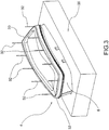
- the automotive light 4 comprises a container body 8, usually of polymeric material, which typically permits the attachment of the automotive light 4 to the relative vehicle.
- the container body 8 may be any shape and size and may even be an element inside the automotive light, for example, not directly associated for example to the bodywork or other fastenings of the associable vehicle.
- the container body 8 delimits a containment housing 12 which houses at least one light source 16, electrically connected to electric connection means for supplying power thereto, and adapted to emit a light beam to propagate outside the automotive light.
- the type of light source 16 used is irrelevant; according to a possible embodiment, the light source 16 is a light source of light emitting diodes (LED).
- the container body 8 is delimited by a first perimetral profile 20.
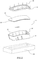
- a lenticular body 24 in turn delimited by a second perimetral profile 28 is joined to the container body 8.
- the lenticular body 24 may be either external to the automotive light 4, so as to define at least one outer wall of the automotive light directly subject to the atmosphere; for the purposes of the present invention the lenticular body may also be internal to the automotive light 4, i.e. not directly subject to the external atmosphere and in turn covered directly or indirectly by one or more screens or covering panels.
- the lenticular body 24 is adapted to close the containment housing 12 and adapted to transmit to the outside of the automotive light 4 the light beam produced by the light source 16.
- the lenticular body 24 is made of at least partially transparent or semi-transparent or translucent material, and may also comprise one or more opaque portions, so as to allow in any case the at least partial crossing of the light beam produced by the light source 16.
- the second perimetral profile 28 is counter-shaped relative to the first perimetral profile 20 so as to be coupled with the latter according to a shaped coupling, in the assembled configuration of the automotive light 4.
- the assembly of the automotive light 4 comprises the step of joining at least partially to each other the respective first and second perimetral profiles 20, 28.
- the step is provided for of arranging the lenticular body 24 to close the containment housing 12 of the container body 8 so as to join the respective first and second perimetral profiles 20,28,
- the method of manufacture of the automotive light according to the invention provides for joining the lenticular body and the container body to each other in correspondence of said perimetral profiles 20, 28, by means of laser welding.
- the laser welding process may be realised with different techniques, for example, with simultaneous laser welding, almost-simultaneous laser welding, border laser welding, mask laser welding, radial laser welding, globe laser welding, etc.
- At least a laser source is provided for which emits a laser beam or a light beam or an electromagnetic radiation having a characteristic emission spectrum.
- Characteristic emission spectrum is taken to mean an electromagnetic radiation emitted substantially at a certain frequency or having a certain wavelength.
- said laser source is a laser diode which emits a laser beam.
- the laser source comprises a CO 2 laser, in which the laser beam is produced by a gas mixture comprising CO 2 , or a YAG laser, in which the laser beam is produced by a solid state crystal.
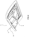
- the laser source emits a light beam that can be sent directly to the lenticular body 24; in a preferred embodiment the laser source is associated with an optical fibre 32 inserted in a matrix/guide 33 which has the function of supporting the optical fibre 32 as well as guiding the light beam emitted by the laser source.
- the welding preferably takes place after blocking the container body 8 in a respective attachment block 35.
- the step of providing the lenticular body 24 envisages that said lenticular body 24 be obtained by means of a moulding technique so as to have a lenticular body 24 comprising at least a first and a second layer 36,40 at least partially overlapping and integral to each other.
- the first layer 36 is facing the outside of the automotive light 4 and the second layer 40 is facing towards the containment housing 12.
- said layers 36, 40 advantageously have different transmittance values in relation to the emission spectrum of the laser source.
- the layers 36, 40 have different optical properties such that, in correspondence with the characteristic emission spectrum of the laser source, they show different transmittance values. Consequently, the light beam emitted by the laser source will be transmitted or absorbed by the two layers 36, 40 differently.
- the welding of the lenticular body 24 on the container body 8 is a laser welding, wherein the light beam emitted by the laser source is routed towards the perimetral profiles 20, 28 so as to reach the first perimetral profile 20 of the container body 8 after passing through at least one of the layers 36, 40 of the lenticular body 24 having different transmittance values in relation to the emission spectrum.
- the container body 8 acts as an absorbing member in relation to the light beam emitted by the laser source and the lenticular body 24 acts as a transmissive member of said light beam.
- the light radiation emitted by the laser source passes through both the first layer 36 and the second layer 40 of the lenticular body 24 before reaching the welding area positioned at an interface 44 between the first and second perimetral profiles 20, 28.
- one of said layers 36, 40 of the lenticular body 24 is a layer in a polymer material having transmittance values, measured in the emission spectrum of the laser source, greater than 90%.
- At least one of said layers 36, 40 of the lenticular body 24 is a layer made of a substantially clear material.
- At least one of said layers 36, 40 is made of a polymer material having a desired colour, said layer 36, 40 having a transmittance sufficient to not soften the material hit by the light beam and to transmit the light beam towards the perimetral profiles 20, 28 and towards the interface 44.
- first layer 36 and the second layer 40 of the lenticular body 24 are made with the same material.
- the material of the first and/or second layer 36, 40 of the lenticular body 24 is a resin such as PMMA, PC and the like.
- the layer 36, 40 of the lenticular body 24 having the greater transmittance value has a greater thickness than the layer 40, 36 having a lower transmittance value.
- the lenticular body 24 has an overall thickness of 4.5 mm, wherein 2 mm are for the layer 36, 40 having the lower transmittance value and 2.5 mm are for the layer 40, 36 having the greater transmittance value.
- said first and second layers 36, 40 of the lenticular body 24 are obtained by a technique of co-moulding.
- the lenticular body 24 is obtained with a multicolour injection moulding technique, wherein an equipment is used provided with a mould consisting of a fixed platform having at least two matrix half-moulds, and a rotating platform having a punch half-mould, able to move relative to the fixed platform, so as to couple the punch half-mould with each matrix half-mould present on the fixed platform.
- the lenticular body 24 has, as seen, at least two layers 36,40 integral with each other and at least partially overlapping.
- the two or more layers 36, 40 are preferably made of different colours: typically one of the layers is clear, or substantially transparent, the other is coloured since it has to filter the light emitted by the light source so that the light beam produced in output from the light has the desired colour; for example, red for a side light or stop light, orange for an indicator light and the like.
- the colouration i.e. doping of the material to obtain a coloured layer of the lenticular body, modifies, for the same spectrum of the incident beam, the transmittance: in general, the transmittance increases in the absence of doping, i.e. in the presence of a clear layer and decreases as said doping increases.
- the lenticular body 24 must have one or more coloured pieces so that the light beam in output has the desired colour.
- the lenticular bodies welded with laser technology have coloured portions in a single piece: in other words, the lenticular body is composed of a single coloured layer and then doped in the desired colour.
- This solution is not very efficient at the moment of trying to weld the lenticular body 24 to the container body 8 by means of laser welding.
- the lenticular body instead comprises at least two layers coloured with different dopings in order to increase, at least partially, the overall transmittance of said lenticular body.
- This effect can be obtained by applying a clear layer (with transmittance greater than 90%) to a coloured layer, for example, red, with transmittance less than 90%, or overlapping two layers, both coloured, so as to provide a light in output of the desired colour and to have a total transmittance of the lenticular body better than in the case of a corresponding single coloured layer.
- a clear layer with transmittance greater than 90%
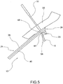
- the lenticular body 24, at the second perimetral profile 28 comprises a second contact edge 48 with the container body 8 wherein said second contact edge 48 follows the respective second perimetral profile 28 and projects therefrom in the direction of the container body 8.
- the light radiation emitted by the laser source is directed so as to be channelled in the second contact edge 48 and to impact on the first perimetral profile 20 of the container body 8.
- the second contact edge 48 is integral with the second layer 40 of the lenticular body 24.
- the second layer 40 of the lenticular body 24 is the layer having a higher transmittance and also encompasses the second contact edge 48: this way it further increases the path of the light beam inside the layer having a higher transmittance.
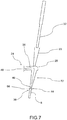
- the second contact edge 48 comprises overlapping portions of the first and second layers 36, 40 ( figures 6-7 ).
- said overlapping portions 36',40' comprise at least one protrusion 36' of the first layer 36 at least partially penetrated into the second contact edge 48 of the second layer 40.
- the light radiation emitted by the laser source is directed according to a direction substantially perpendicular to the layers 36, 40 of the lenticular body, at said perimetral profiles 20,28 ( figure 5 ).
- the lenticular body 24 at the second perimetral profile 28 comprises a folded portion 52 towards the container body 8, the folded portion 52 being integral with the lenticular body 24 and defining the second contact edge 48 with the container body 8; the folded portion 52 comprising in turn an overlapping of the first and second layers 36, 40 of the lenticular body 24 ( figure 6-7 ).
- the light radiation emitted by the laser source is directed at the second contact edge 48 according to a direction substantially parallel to the layers 36, 40 of the lenticular body 24.
- the light radiation is directed so as to channel itself into the second contact edge 48, along each of the layers 36, 40 of the lenticular body and to impact on the first perimetral profile 20.
- the container body 8, at the first perimetral profile 20, comprises a first contact edge 56, in contact with the container body 8, said first contact edge 56 following the respective first perimetral profile 20 and projecting therefrom in the direction of the lenticular body 24.
- the first perimetral profile 20 is at least partially counter-shaped relative to the second perimetral profile 28, and the first perimetral profile 20 has an abutment wall 60 which receives in abutment the second contact edge 56.
- the abutment wall 60 forms the interface 44 between the lenticular body 24 and the container body 8.
- said abutment wall 60 has a thickness greater than or equal to a corresponding supporting wall 64 of the second contact edge 48.
- the laser welding techniques for the manufacturing method according to the present invention may be of various types; for example the laser welding step is performed by one or more optical fibres which simultaneously emit respective light radiation on separate, predetermined portions of said perimetral profiles 20, 28, according to a 'simultaneous' welding technique.
- the manufacturing method according to the invention makes it possible to overcome the drawbacks of the prior art.
- the laser welding technique according to the present invention is not only not inconvenient compared to alternative welding techniques of the prior art but may even be better both in terms of cost and time, for the same quality of the welding joint, compared to the solutions of the prior art in the field of automotive lights.
- the light beam on the interface portion is thus suitable to obtain a welded joint having excellent mechanical qualities, without waste of luminous power.
- the laser welding step regardless of the technique used to perform it, for example of the 'border' or 'simultaneous' type, is quick and reliable, allowing a further reduction of assembly costs for the same quality of the joint compared to the prior art.
- the moulding technique of the lenticular body comprising at least two layers makes it possible to obtain perimeter profiles and/or contact edges of the lenticular body having thicknesses greater than those obtainable using conventional moulding techniques. Thanks to the increased thickness of the perimetral profiles and relative contact edges of the lenticular body it is possible to channel and transmit to the container body a greater part of the light beam to the benefit of a greater heating of the weld joint and, therefore, an energy saving due to a greater energy efficiency.
- a light beam having a higher light output in order, for example, to weld in interface zones (between the lenticular body and the container body) relatively distant from the laser source emitter, for example, for automotive lights having particular geometries and particularly pronounced heights or thicknesses of the lenticular body.
- the light beam while placing the laser source and the relative optical fibres at the limit of contact with the outer surface of the lenticular body, will have to cover a relatively long path before reaching said interface surface.
- the light beam will be at least partially absorbed by the lenticular body and thus, in order to locally melt the container body (absorbent) at the interface surface, a high power light beam would need to be sent.
- This way on the one hand would increase consumption and on the other risk producing unwanted melting or softening in different portions of the lenticular body.
- the presence of overly narrow perimetral profiles and relative contact edges of the lenticular body would lead to the non-melting of the plastic material at the interface surface making the welding impossible.
- the lenticular body of at least two layers it is possible to create profiles and edges of adequate thickness, obtaining an effective transmission of the light beam at elevated distances or depths i.e. the distance between the outer surface of the lenticular body and the interface surface between the lenticular body and the container body, thus making laser welding with any geometry of the automotive light possible and efficient.
Landscapes
- Engineering & Computer Science (AREA)
- Physics & Mathematics (AREA)
- Mechanical Engineering (AREA)
- Optics & Photonics (AREA)
- Health & Medical Sciences (AREA)
- Electromagnetism (AREA)
- Toxicology (AREA)
- Microelectronics & Electronic Packaging (AREA)
- General Engineering & Computer Science (AREA)
- Spectroscopy & Molecular Physics (AREA)
- Lining Or Joining Of Plastics Or The Like (AREA)
- Laser Beam Processing (AREA)
- Non-Portable Lighting Devices Or Systems Thereof (AREA)
Priority Applications (1)
| Application Number | Priority Date | Filing Date | Title |
|---|---|---|---|
| PL15160112T PL2923819T3 (pl) | 2014-03-28 | 2015-03-20 | Sposób wytwarzania lampy samochodowej |
Applications Claiming Priority (1)
| Application Number | Priority Date | Filing Date | Title |
|---|---|---|---|
| ITPD20140080 | 2014-03-28 |
Publications (2)
| Publication Number | Publication Date |
|---|---|
| EP2923819A1 EP2923819A1 (en) | 2015-09-30 |
| EP2923819B1 true EP2923819B1 (en) | 2019-09-04 |
Family
ID=51136633
Family Applications (1)
| Application Number | Title | Priority Date | Filing Date |
|---|---|---|---|
| EP15160112.7A Active EP2923819B1 (en) | 2014-03-28 | 2015-03-20 | Method of manufacture of an automotive light |
Country Status (5)
| Country | Link |
|---|---|
| US (1) | US9482403B2 (pl) |
| EP (1) | EP2923819B1 (pl) |
| CN (1) | CN104943159B (pl) |
| ES (1) | ES2759778T3 (pl) |
| PL (1) | PL2923819T3 (pl) |
Cited By (1)
| Publication number | Priority date | Publication date | Assignee | Title |
|---|---|---|---|---|
| EP3470212B1 (en) * | 2017-10-12 | 2025-01-01 | MARELLI AUTOMOTIVE LIGHTING ITALY S.p.A. | Simultaneous laser welding equipment of a vehicle light and simultaneous laser welding method of a vehicle light |
Families Citing this family (10)
| Publication number | Priority date | Publication date | Assignee | Title |
|---|---|---|---|---|
| HUE052369T2 (hu) * | 2014-05-30 | 2021-04-28 | Marelli Automotive Lighting Italy Spa | Gépjármû-lámpa lézerhegesztési eljárása |
| PL2957418T3 (pl) | 2014-06-19 | 2020-09-21 | Marelli Automotive Lighting Italy S.p.A. | Urządzenie do wytwarzania reflektora samochodowego i sposób równoczesnego zgrzewania laserowego reflektora samochodowego |
| CN106641948A (zh) * | 2015-11-02 | 2017-05-10 | 丹阳市米可汽车零部件厂 | 一种车灯的制造工艺 |
| CN105479728A (zh) * | 2016-02-26 | 2016-04-13 | 上海信耀电子有限公司 | 一种汽车前灯装置的焊接工艺 |
| DE102017104432B4 (de) * | 2017-03-03 | 2025-12-24 | Hella Kgaa Hueck & Co. | Verfahren zur Anordnung einer Funktionsschicht an ein Kunststoffbauteil einer Beleuchtungseinrichtung |
| IT201700041997A1 (it) * | 2017-04-14 | 2018-10-14 | Automotive Lighting Italia Spa | Attrezzatura di saldatura laser simultanea di un fanale automobilistico e metodo di saldatura laser simultanea di un fanale automobilistico |
| US10337696B2 (en) * | 2017-09-22 | 2019-07-02 | Ford Global Technologies, Llc | Vehicle lens assembly and lens manufacturing method |
| EP3839325A1 (en) * | 2019-12-18 | 2021-06-23 | Marelli Automotive Lighting Italy S.p.A. | Automotive lighting and/or signaling device |
| US12399487B2 (en) * | 2020-04-08 | 2025-08-26 | BWXT Advanced Technologies LLC | In-situ inspection method based on digital data model of weld |
| EP4527595A1 (en) * | 2023-09-25 | 2025-03-26 | Marelli Automotive Lighting Italy S.p.A. Con Socio Unico | Assembly method of an automotive lighting unit and machine implementing such method |
Family Cites Families (11)
| Publication number | Priority date | Publication date | Assignee | Title |
|---|---|---|---|---|
| JP2908176B2 (ja) * | 1993-05-18 | 1999-06-21 | 株式会社小糸製作所 | 車輌用灯具の合成樹脂製積層レンズ及びその成形方法 |
| JP3796366B2 (ja) * | 1999-03-08 | 2006-07-12 | 株式会社小糸製作所 | 車輌用灯具のレンズ、車輌用灯具のレンズの成形方法及び車輌用灯具のレンズの成型装置 |
| JP3972621B2 (ja) * | 2001-10-09 | 2007-09-05 | 市光工業株式会社 | 車両用灯具およびそのレーザ溶着方法 |
| JP4437681B2 (ja) * | 2004-03-15 | 2010-03-24 | 株式会社小糸製作所 | 灯具の製造方法及び製造装置 |
| JP2005339873A (ja) * | 2004-05-25 | 2005-12-08 | Koito Mfg Co Ltd | 車輌用灯具の製造方法 |
| JP2006167946A (ja) * | 2004-12-13 | 2006-06-29 | Koito Mfg Co Ltd | 車輌用灯具及び光線溶着方法 |
| JP4493577B2 (ja) * | 2005-10-11 | 2010-06-30 | 株式会社小糸製作所 | 車輌用灯具 |
| JP5595799B2 (ja) * | 2010-06-11 | 2014-09-24 | 株式会社小糸製作所 | レーザ溶着構造 |
| JP2012028143A (ja) * | 2010-07-22 | 2012-02-09 | Stanley Electric Co Ltd | 車両用灯具、及び、車両用灯具製造方法 |
| KR101797764B1 (ko) * | 2010-06-24 | 2017-11-15 | 스탠리 일렉트릭 컴퍼니, 리미티드 | 차량용 등 기구 및 차량용 등 기구 제조 방법 |
| JP5911199B2 (ja) * | 2011-03-22 | 2016-04-27 | 株式会社小糸製作所 | 溶着方法及び溶着装置 |
-
2015
- 2015-03-20 ES ES15160112T patent/ES2759778T3/es active Active
- 2015-03-20 PL PL15160112T patent/PL2923819T3/pl unknown
- 2015-03-20 EP EP15160112.7A patent/EP2923819B1/en active Active
- 2015-03-25 US US14/667,789 patent/US9482403B2/en active Active
- 2015-03-30 CN CN201510146021.9A patent/CN104943159B/zh active Active
Non-Patent Citations (1)
| Title |
|---|
| None * |
Cited By (1)
| Publication number | Priority date | Publication date | Assignee | Title |
|---|---|---|---|---|
| EP3470212B1 (en) * | 2017-10-12 | 2025-01-01 | MARELLI AUTOMOTIVE LIGHTING ITALY S.p.A. | Simultaneous laser welding equipment of a vehicle light and simultaneous laser welding method of a vehicle light |
Also Published As
| Publication number | Publication date |
|---|---|
| PL2923819T3 (pl) | 2020-08-24 |
| CN104943159B (zh) | 2020-03-31 |
| US9482403B2 (en) | 2016-11-01 |
| US20150276158A1 (en) | 2015-10-01 |
| EP2923819A1 (en) | 2015-09-30 |
| CN104943159A (zh) | 2015-09-30 |
| ES2759778T3 (es) | 2020-05-12 |
Similar Documents
| Publication | Publication Date | Title |
|---|---|---|
| EP2923819B1 (en) | Method of manufacture of an automotive light | |
| EP2923820B1 (en) | Method of laser welding of an automotive light | |
| US9862301B2 (en) | Vehicular rear panel | |
| EP2957418B1 (en) | Apparatus for making an automotive headlight and method of simultaneous laser welding of an automotive headlight | |
| US20150343701A1 (en) | Method of laser welding of an automotive light and relative automotive light | |
| EP3115678B1 (en) | Method of making a vehicle light and related vehicle light | |
| JP5595799B2 (ja) | レーザ溶着構造 | |
| JP6354520B2 (ja) | 発光装置 | |
| KR101387641B1 (ko) | 이색사출렌즈를 구비하는 헤드램프장치 및 그 제조방법 | |
| EP3470212B1 (en) | Simultaneous laser welding equipment of a vehicle light and simultaneous laser welding method of a vehicle light | |
| CN216814034U (zh) | 用于车辆的贯穿灯和具有它的车辆 | |
| KR20180099154A (ko) | 차량용 인테리어 램프 유닛 및 그 제조방법 | |
| JP2017107646A (ja) | アウターカバーを加温する熱源を備えた車両用灯具 | |
| JP2018010805A (ja) | 車両用灯具及び車両用灯具の製造方法 | |
| EP3751192B1 (en) | Outer lens for lighting fixtures for vehicles, lighting fixture for vehicles provided with said outer lens, and method for producing said lighting fixture for vehicles | |
| CN120620662A (zh) | 灯罩的加工方法、灯具及载具 | |
| JP2018203159A (ja) | 車両用外装ユニット及び車両用外装ユニットの製造方法 |
Legal Events
| Date | Code | Title | Description |
|---|---|---|---|
| PUAI | Public reference made under article 153(3) epc to a published international application that has entered the european phase |
Free format text: ORIGINAL CODE: 0009012 |
|
| AK | Designated contracting states |
Kind code of ref document: A1 Designated state(s): AL AT BE BG CH CY CZ DE DK EE ES FI FR GB GR HR HU IE IS IT LI LT LU LV MC MK MT NL NO PL PT RO RS SE SI SK SM TR |
|
| AX | Request for extension of the european patent |
Extension state: BA ME |
|
| 17P | Request for examination filed |
Effective date: 20160325 |
|
| RBV | Designated contracting states (corrected) |
Designated state(s): AL AT BE BG CH CY CZ DE DK EE ES FI FR GB GR HR HU IE IS IT LI LT LU LV MC MK MT NL NO PL PT RO RS SE SI SK SM TR |
|
| STAA | Information on the status of an ep patent application or granted ep patent |
Free format text: STATUS: EXAMINATION IS IN PROGRESS |
|
| 17Q | First examination report despatched |
Effective date: 20171106 |
|
| GRAP | Despatch of communication of intention to grant a patent |
Free format text: ORIGINAL CODE: EPIDOSNIGR1 |
|
| STAA | Information on the status of an ep patent application or granted ep patent |
Free format text: STATUS: GRANT OF PATENT IS INTENDED |
|
| RIC1 | Information provided on ipc code assigned before grant |
Ipc: B29C 65/00 20060101ALI20190326BHEP Ipc: F21S 41/29 20180101ALI20190326BHEP Ipc: B29C 65/16 20060101AFI20190326BHEP Ipc: B29K 101/12 20060101ALI20190326BHEP Ipc: B29L 11/00 20060101ALI20190326BHEP Ipc: F21V 9/08 20180101ALI20190326BHEP Ipc: F21Y 115/30 20160101ALI20190326BHEP Ipc: F21S 43/27 20180101ALI20190326BHEP Ipc: B29L 31/00 20060101ALI20190326BHEP Ipc: F21Y 115/10 20160101ALI20190326BHEP Ipc: B29L 31/30 20060101ALI20190326BHEP |
|
| INTG | Intention to grant announced |
Effective date: 20190424 |
|
| GRAS | Grant fee paid |
Free format text: ORIGINAL CODE: EPIDOSNIGR3 |
|
| GRAA | (expected) grant |
Free format text: ORIGINAL CODE: 0009210 |
|
| STAA | Information on the status of an ep patent application or granted ep patent |
Free format text: STATUS: THE PATENT HAS BEEN GRANTED |
|
| AK | Designated contracting states |
Kind code of ref document: B1 Designated state(s): AL AT BE BG CH CY CZ DE DK EE ES FI FR GB GR HR HU IE IS IT LI LT LU LV MC MK MT NL NO PL PT RO RS SE SI SK SM TR |
|
| REG | Reference to a national code |
Ref country code: GB Ref legal event code: FG4D |
|
| REG | Reference to a national code |
Ref country code: CH Ref legal event code: EP |
|
| REG | Reference to a national code |
Ref country code: AT Ref legal event code: REF Ref document number: 1174767 Country of ref document: AT Kind code of ref document: T Effective date: 20190915 |
|
| REG | Reference to a national code |
Ref country code: DE Ref legal event code: R096 Ref document number: 602015037023 Country of ref document: DE |
|
| REG | Reference to a national code |
Ref country code: IE Ref legal event code: FG4D |
|
| REG | Reference to a national code |
Ref country code: DE Ref legal event code: R081 Ref document number: 602015037023 Country of ref document: DE Owner name: MARELLI AUTOMOTIVE LIGHTING ITALY S.P.A., VENA, IT Free format text: FORMER OWNER: AUTOMOTIVE LIGHTING ITALIA S.P.A. A SOCIO UNICO, VENARIA REALE, TORINO, IT Ref country code: DE Ref legal event code: R082 Ref document number: 602015037023 Country of ref document: DE Representative=s name: DREISS PATENTANWAELTE PARTG MBB, DE Ref country code: DE Ref legal event code: R081 Ref document number: 602015037023 Country of ref document: DE Owner name: MARELLI AUTOMOTIVE LIGHTING ITALY S.P.A., IT Free format text: FORMER OWNER: AUTOMOTIVE LIGHTING ITALIA S.P.A. A SOCIO UNICO, VENARIA REALE, TORINO, IT |
|
| RAP2 | Party data changed (patent owner data changed or rights of a patent transferred) |
Owner name: MARELLI AUTOMOTIVE LIGHTING ITALY S.P.A. |
|
| REG | Reference to a national code |
Ref country code: NL Ref legal event code: MP Effective date: 20190904 |
|
| REG | Reference to a national code |
Ref country code: LT Ref legal event code: MG4D |
|
| PG25 | Lapsed in a contracting state [announced via postgrant information from national office to epo] |
Ref country code: FI Free format text: LAPSE BECAUSE OF FAILURE TO SUBMIT A TRANSLATION OF THE DESCRIPTION OR TO PAY THE FEE WITHIN THE PRESCRIBED TIME-LIMIT Effective date: 20190904 Ref country code: LT Free format text: LAPSE BECAUSE OF FAILURE TO SUBMIT A TRANSLATION OF THE DESCRIPTION OR TO PAY THE FEE WITHIN THE PRESCRIBED TIME-LIMIT Effective date: 20190904 Ref country code: BG Free format text: LAPSE BECAUSE OF FAILURE TO SUBMIT A TRANSLATION OF THE DESCRIPTION OR TO PAY THE FEE WITHIN THE PRESCRIBED TIME-LIMIT Effective date: 20191204 Ref country code: NO Free format text: LAPSE BECAUSE OF FAILURE TO SUBMIT A TRANSLATION OF THE DESCRIPTION OR TO PAY THE FEE WITHIN THE PRESCRIBED TIME-LIMIT Effective date: 20191204 Ref country code: SE Free format text: LAPSE BECAUSE OF FAILURE TO SUBMIT A TRANSLATION OF THE DESCRIPTION OR TO PAY THE FEE WITHIN THE PRESCRIBED TIME-LIMIT Effective date: 20190904 Ref country code: HR Free format text: LAPSE BECAUSE OF FAILURE TO SUBMIT A TRANSLATION OF THE DESCRIPTION OR TO PAY THE FEE WITHIN THE PRESCRIBED TIME-LIMIT Effective date: 20190904 |
|
| PG25 | Lapsed in a contracting state [announced via postgrant information from national office to epo] |
Ref country code: LV Free format text: LAPSE BECAUSE OF FAILURE TO SUBMIT A TRANSLATION OF THE DESCRIPTION OR TO PAY THE FEE WITHIN THE PRESCRIBED TIME-LIMIT Effective date: 20190904 Ref country code: RS Free format text: LAPSE BECAUSE OF FAILURE TO SUBMIT A TRANSLATION OF THE DESCRIPTION OR TO PAY THE FEE WITHIN THE PRESCRIBED TIME-LIMIT Effective date: 20190904 Ref country code: GR Free format text: LAPSE BECAUSE OF FAILURE TO SUBMIT A TRANSLATION OF THE DESCRIPTION OR TO PAY THE FEE WITHIN THE PRESCRIBED TIME-LIMIT Effective date: 20191205 Ref country code: AL Free format text: LAPSE BECAUSE OF FAILURE TO SUBMIT A TRANSLATION OF THE DESCRIPTION OR TO PAY THE FEE WITHIN THE PRESCRIBED TIME-LIMIT Effective date: 20190904 |
|
| REG | Reference to a national code |
Ref country code: AT Ref legal event code: MK05 Ref document number: 1174767 Country of ref document: AT Kind code of ref document: T Effective date: 20190904 |
|
| PG25 | Lapsed in a contracting state [announced via postgrant information from national office to epo] |
Ref country code: EE Free format text: LAPSE BECAUSE OF FAILURE TO SUBMIT A TRANSLATION OF THE DESCRIPTION OR TO PAY THE FEE WITHIN THE PRESCRIBED TIME-LIMIT Effective date: 20190904 Ref country code: AT Free format text: LAPSE BECAUSE OF FAILURE TO SUBMIT A TRANSLATION OF THE DESCRIPTION OR TO PAY THE FEE WITHIN THE PRESCRIBED TIME-LIMIT Effective date: 20190904 Ref country code: PT Free format text: LAPSE BECAUSE OF FAILURE TO SUBMIT A TRANSLATION OF THE DESCRIPTION OR TO PAY THE FEE WITHIN THE PRESCRIBED TIME-LIMIT Effective date: 20200106 Ref country code: RO Free format text: LAPSE BECAUSE OF FAILURE TO SUBMIT A TRANSLATION OF THE DESCRIPTION OR TO PAY THE FEE WITHIN THE PRESCRIBED TIME-LIMIT Effective date: 20190904 Ref country code: NL Free format text: LAPSE BECAUSE OF FAILURE TO SUBMIT A TRANSLATION OF THE DESCRIPTION OR TO PAY THE FEE WITHIN THE PRESCRIBED TIME-LIMIT Effective date: 20190904 |
|
| REG | Reference to a national code |
Ref country code: ES Ref legal event code: FG2A Ref document number: 2759778 Country of ref document: ES Kind code of ref document: T3 Effective date: 20200512 |
|
| PG25 | Lapsed in a contracting state [announced via postgrant information from national office to epo] |
Ref country code: SM Free format text: LAPSE BECAUSE OF FAILURE TO SUBMIT A TRANSLATION OF THE DESCRIPTION OR TO PAY THE FEE WITHIN THE PRESCRIBED TIME-LIMIT Effective date: 20190904 Ref country code: SK Free format text: LAPSE BECAUSE OF FAILURE TO SUBMIT A TRANSLATION OF THE DESCRIPTION OR TO PAY THE FEE WITHIN THE PRESCRIBED TIME-LIMIT Effective date: 20190904 Ref country code: IS Free format text: LAPSE BECAUSE OF FAILURE TO SUBMIT A TRANSLATION OF THE DESCRIPTION OR TO PAY THE FEE WITHIN THE PRESCRIBED TIME-LIMIT Effective date: 20200224 |
|
| REG | Reference to a national code |
Ref country code: DE Ref legal event code: R097 Ref document number: 602015037023 Country of ref document: DE |
|
| PLBE | No opposition filed within time limit |
Free format text: ORIGINAL CODE: 0009261 |
|
| STAA | Information on the status of an ep patent application or granted ep patent |
Free format text: STATUS: NO OPPOSITION FILED WITHIN TIME LIMIT |
|
| PG2D | Information on lapse in contracting state deleted |
Ref country code: IS |
|
| PG25 | Lapsed in a contracting state [announced via postgrant information from national office to epo] |
Ref country code: DK Free format text: LAPSE BECAUSE OF FAILURE TO SUBMIT A TRANSLATION OF THE DESCRIPTION OR TO PAY THE FEE WITHIN THE PRESCRIBED TIME-LIMIT Effective date: 20190904 Ref country code: IS Free format text: LAPSE BECAUSE OF FAILURE TO SUBMIT A TRANSLATION OF THE DESCRIPTION OR TO PAY THE FEE WITHIN THE PRESCRIBED TIME-LIMIT Effective date: 20200105 |
|
| 26N | No opposition filed |
Effective date: 20200605 |
|
| PG25 | Lapsed in a contracting state [announced via postgrant information from national office to epo] |
Ref country code: SI Free format text: LAPSE BECAUSE OF FAILURE TO SUBMIT A TRANSLATION OF THE DESCRIPTION OR TO PAY THE FEE WITHIN THE PRESCRIBED TIME-LIMIT Effective date: 20190904 |
|
| PG25 | Lapsed in a contracting state [announced via postgrant information from national office to epo] |
Ref country code: MC Free format text: LAPSE BECAUSE OF FAILURE TO SUBMIT A TRANSLATION OF THE DESCRIPTION OR TO PAY THE FEE WITHIN THE PRESCRIBED TIME-LIMIT Effective date: 20190904 |
|
| REG | Reference to a national code |
Ref country code: CH Ref legal event code: PL |
|
| REG | Reference to a national code |
Ref country code: BE Ref legal event code: MM Effective date: 20200331 |
|
| PG25 | Lapsed in a contracting state [announced via postgrant information from national office to epo] |
Ref country code: LU Free format text: LAPSE BECAUSE OF NON-PAYMENT OF DUE FEES Effective date: 20200320 |
|
| PG25 | Lapsed in a contracting state [announced via postgrant information from national office to epo] |
Ref country code: IE Free format text: LAPSE BECAUSE OF NON-PAYMENT OF DUE FEES Effective date: 20200320 Ref country code: CH Free format text: LAPSE BECAUSE OF NON-PAYMENT OF DUE FEES Effective date: 20200331 Ref country code: LI Free format text: LAPSE BECAUSE OF NON-PAYMENT OF DUE FEES Effective date: 20200331 |
|
| PG25 | Lapsed in a contracting state [announced via postgrant information from national office to epo] |
Ref country code: BE Free format text: LAPSE BECAUSE OF NON-PAYMENT OF DUE FEES Effective date: 20200331 |
|
| PG25 | Lapsed in a contracting state [announced via postgrant information from national office to epo] |
Ref country code: MT Free format text: LAPSE BECAUSE OF FAILURE TO SUBMIT A TRANSLATION OF THE DESCRIPTION OR TO PAY THE FEE WITHIN THE PRESCRIBED TIME-LIMIT Effective date: 20190904 Ref country code: CY Free format text: LAPSE BECAUSE OF FAILURE TO SUBMIT A TRANSLATION OF THE DESCRIPTION OR TO PAY THE FEE WITHIN THE PRESCRIBED TIME-LIMIT Effective date: 20190904 |
|
| PG25 | Lapsed in a contracting state [announced via postgrant information from national office to epo] |
Ref country code: MK Free format text: LAPSE BECAUSE OF FAILURE TO SUBMIT A TRANSLATION OF THE DESCRIPTION OR TO PAY THE FEE WITHIN THE PRESCRIBED TIME-LIMIT Effective date: 20190904 |
|
| P01 | Opt-out of the competence of the unified patent court (upc) registered |
Effective date: 20230526 |
|
| PGFP | Annual fee paid to national office [announced via postgrant information from national office to epo] |
Ref country code: CZ Payment date: 20240226 Year of fee payment: 10 Ref country code: GB Payment date: 20240221 Year of fee payment: 10 |
|
| PGFP | Annual fee paid to national office [announced via postgrant information from national office to epo] |
Ref country code: TR Payment date: 20240223 Year of fee payment: 10 Ref country code: PL Payment date: 20240226 Year of fee payment: 10 |
|
| PGFP | Annual fee paid to national office [announced via postgrant information from national office to epo] |
Ref country code: ES Payment date: 20240402 Year of fee payment: 10 |
|
| PG25 | Lapsed in a contracting state [announced via postgrant information from national office to epo] |
Ref country code: CZ Free format text: LAPSE BECAUSE OF NON-PAYMENT OF DUE FEES Effective date: 20250320 |
|
| GBPC | Gb: european patent ceased through non-payment of renewal fee |
Effective date: 20250320 |
|
| PG25 | Lapsed in a contracting state [announced via postgrant information from national office to epo] |
Ref country code: GB Free format text: LAPSE BECAUSE OF NON-PAYMENT OF DUE FEES Effective date: 20250320 |
|
| PGFP | Annual fee paid to national office [announced via postgrant information from national office to epo] |
Ref country code: DE Payment date: 20260219 Year of fee payment: 12 |
|
| PGFP | Annual fee paid to national office [announced via postgrant information from national office to epo] |
Ref country code: IT Payment date: 20260219 Year of fee payment: 12 |
|
| PGFP | Annual fee paid to national office [announced via postgrant information from national office to epo] |
Ref country code: FR Payment date: 20260219 Year of fee payment: 12 |