EP2923733A1 - Teilchenstrahlbestrahlungssystem mit geladenen Teilchen - Google Patents
Teilchenstrahlbestrahlungssystem mit geladenen Teilchen Download PDFInfo
- Publication number
- EP2923733A1 EP2923733A1 EP15155323.7A EP15155323A EP2923733A1 EP 2923733 A1 EP2923733 A1 EP 2923733A1 EP 15155323 A EP15155323 A EP 15155323A EP 2923733 A1 EP2923733 A1 EP 2923733A1
- Authority
- EP
- European Patent Office
- Prior art keywords
- irradiation
- charged particle
- particle beam
- dose
- split
- Prior art date
- Legal status (The legal status is an assumption and is not a legal conclusion. Google has not performed a legal analysis and makes no representation as to the accuracy of the status listed.)
- Granted
Links
Images




Classifications
-
- A—HUMAN NECESSITIES
- A61—MEDICAL OR VETERINARY SCIENCE; HYGIENE
- A61N—ELECTROTHERAPY; MAGNETOTHERAPY; RADIATION THERAPY; ULTRASOUND THERAPY
- A61N5/00—Radiation therapy
- A61N5/10—X-ray therapy; Gamma-ray therapy; Particle-irradiation therapy
- A61N5/1077—Beam delivery systems
-
- A—HUMAN NECESSITIES
- A61—MEDICAL OR VETERINARY SCIENCE; HYGIENE
- A61N—ELECTROTHERAPY; MAGNETOTHERAPY; RADIATION THERAPY; ULTRASOUND THERAPY
- A61N5/00—Radiation therapy
- A61N5/10—X-ray therapy; Gamma-ray therapy; Particle-irradiation therapy
- A61N5/103—Treatment planning systems
-
- A—HUMAN NECESSITIES
- A61—MEDICAL OR VETERINARY SCIENCE; HYGIENE
- A61N—ELECTROTHERAPY; MAGNETOTHERAPY; RADIATION THERAPY; ULTRASOUND THERAPY
- A61N5/00—Radiation therapy
- A61N5/10—X-ray therapy; Gamma-ray therapy; Particle-irradiation therapy
- A61N5/1042—X-ray therapy; Gamma-ray therapy; Particle-irradiation therapy with spatial modulation of the radiation beam within the treatment head
- A61N5/1043—Scanning the radiation beam, e.g. spot scanning or raster scanning
-
- A—HUMAN NECESSITIES
- A61—MEDICAL OR VETERINARY SCIENCE; HYGIENE
- A61N—ELECTROTHERAPY; MAGNETOTHERAPY; RADIATION THERAPY; ULTRASOUND THERAPY
- A61N5/00—Radiation therapy
- A61N5/10—X-ray therapy; Gamma-ray therapy; Particle-irradiation therapy
- A61N5/1048—Monitoring, verifying, controlling systems and methods
- A61N5/1064—Monitoring, verifying, controlling systems and methods for adjusting radiation treatment in response to monitoring
- A61N5/1065—Beam adjustment
- A61N5/1067—Beam adjustment in real time, i.e. during treatment
-
- A—HUMAN NECESSITIES
- A61—MEDICAL OR VETERINARY SCIENCE; HYGIENE
- A61N—ELECTROTHERAPY; MAGNETOTHERAPY; RADIATION THERAPY; ULTRASOUND THERAPY
- A61N5/00—Radiation therapy
- A61N5/10—X-ray therapy; Gamma-ray therapy; Particle-irradiation therapy
- A61N5/1048—Monitoring, verifying, controlling systems and methods
- A61N5/1071—Monitoring, verifying, controlling systems and methods for verifying the dose delivered by the treatment plan
-
- A—HUMAN NECESSITIES
- A61—MEDICAL OR VETERINARY SCIENCE; HYGIENE
- A61N—ELECTROTHERAPY; MAGNETOTHERAPY; RADIATION THERAPY; ULTRASOUND THERAPY
- A61N5/00—Radiation therapy
- A61N5/10—X-ray therapy; Gamma-ray therapy; Particle-irradiation therapy
- A61N5/1048—Monitoring, verifying, controlling systems and methods
- A61N2005/1074—Details of the control system, e.g. user interfaces
-
- A—HUMAN NECESSITIES
- A61—MEDICAL OR VETERINARY SCIENCE; HYGIENE
- A61N—ELECTROTHERAPY; MAGNETOTHERAPY; RADIATION THERAPY; ULTRASOUND THERAPY
- A61N5/00—Radiation therapy
- A61N5/10—X-ray therapy; Gamma-ray therapy; Particle-irradiation therapy
- A61N2005/1085—X-ray therapy; Gamma-ray therapy; Particle-irradiation therapy characterised by the type of particles applied to the patient
- A61N2005/1087—Ions; Protons
Definitions
- the present invention relates to a charged particle beam irradiation system for irradiating an affected part such as a tumor with a charged particle beam and treating the affected part.
- JP-2011-177374-A is considered as the related art of the present technique.
- JP-2011-177374-A discloses a charged particle beam irradiation system which can shorten an irradiation time in a particle beam treatment by a spot scanning method.
- the charged particle beam irradiation system includes a charged particle beam generating unit, beam transport unit (s), and beam irradiation apparatus (es).
- a controller calculates the position and the width of the charged particle beam from the output obtained by a beam position measuring apparatus in the beam irradiation apparatus every time when the irradiation to a spot has been completed.
- the treatment it is desired to shorten treatment time in order to reduce a burden on a patient and increase the number of the patients to be treated.
- the spot scanning method there is a method to shorten the irradiation time and improve the dose rate by increasing the irradiation dose which is applied to one irradiation section (spot) at one time and reducing the number of re-paints of the dose.
- a characteristic of the present invention for solving the above-mentioned problem is a charged particle beam irradiation system including a charged particle beam generating unit configured to accelerate and extract a charged particle beam to an irradiation target, scanning electromagnets configured to scan the accelerated charged particle beam, beam irradiation apparatus(es) configured to irradiate the accelerated charged particle beam to a plurality of irradiation spots respectively set for a plurality of layers which is formed by dividing an irradiation target in a traveling direction of the charged particle beam, beam radiation dose measuring apparatus (s) configured to obtain a dose of the charged particle beam passing through the beam irradiation apparatus, and/or a beam position measuring instrument configured to obtain one or both of the position and the width of the charged particle beam scanned by the scanning electromagnets.
- a charged particle beam generating unit configured to accelerate and extract a charged particle beam to an irradiation target
- scanning electromagnets configured to scan the accelerated charged particle beam
- the beam position measuring instrument obtains one or both of the position and/or the width of the charged particle beam for each irradiation spot, and the obtained results are judged whether they are within allowable ranges.
- the beam position measuring instrument obtains one or both of the position and the width of the charged particle beam for each split during irradiation to the irradiation spot with the charged particle beam with respect to a split of which a dose is managed by dividing a part of or all of the plurality of irradiation spots into a plurality of irradiation sections, and the obtained results are judged whether they are within allowable ranges.
- irradiation time of the charged particle beam relative to the irradiation target can be shortened.
- FIG. 1 is a schematic diagram of an overall construction of a charged particle beam irradiation system 1 according to the present embodiment.
- the charged particle beam irradiation system 1 uses a proton beam as a charged particle beam.
- An affected part of a cancer which is an irradiation target is irradiated with the charged particle beam.
- a heavy particle beam (for example, a carbon beam) may be used instead of the proton beam.
- the charged particle beam irradiation system 1 includes a charged particle beam generating unit 2, beam transport unit(s) 3, beam irradiation apparatus(es) 5 and a controller 6.
- the beam irradiation apparatus 5 and a patient table 41 are arranged in a treatment room 4.
- the beam irradiation apparatus 5 is arranged opposed to the treatment table 41.
- the charged particle beam generating unit 2 includes an ion source (not shown), a linear accelerator (linac) 8 which is a pre-accelerator, and a circular accelerator (synchrotron) 9.
- the linear accelerator 8 accelerates charged particles generated by the ion source until they become a predetermined energy and injects the pre-accelerated charged particles into the synchrotron 9.
- the synchrotron 9 accelerates the injected charged particles until they become a predetermined energy and the charged particles are extracted from the synchrotron 9.
- the synchrotron is exemplified as the circular accelerator.
- an accelerator, which does not have the pre-accelerator 8, such as a cyclotron or a synchro-cyclotron may be used instead of the synchrotron.
- the synchrotron 9 includes a circular beam duct 21 for configuring an orbit of the charged particle beam, a plurality of bending electromagnets 22, a plurality of quadrupole electromagnets (not shown), an injector 23, a high frequency applying apparatus 24 for extraction, an extraction deflector 28, an acceleration unit (acceleration cavity) 29 which applies a high-frequency voltage to the charged particle beam.
- the high frequency applying apparatus 24 includes a pair of high-frequency electrodes 25 for extraction, an open/close switch 26, and a high-frequency power source 27.
- the high-frequency electrodes 25 is provided in the beam duct 21 and connected to the high-frequency power source 27 via the open/close switch 26.
- the acceleration unit 29, the plurality of bending electromagnets 22, the quadrupole electromagnets, and the extraction deflector 28 are arranged along the beam duct 21 as indicated in Fig. 1 .
- a high-frequency power source apparatus (not shown) is connected to the acceleration unit 29.
- the beam transport unit 3 includes a beam path (beam duct) 32 for connecting the synchrotron 9 with the beam irradiation apparatus 5.
- the beam transport unit 3 also includes a plurality of quadrupole electromagnets (not shown) and a plurality of bending electromagnets 31 on the beam path 32.
- the beam path 32 is connected to the circular beam duct 21 of the synchrotron 9 near the extraction deflector 28.
- the beam transport unit 3 delivers the charged particle beam accelerated by the charged particle beam generating unit 2 to the beam irradiation apparatus 5.
- the beam irradiation apparatus 5 includes a casing 50, a first scanning electromagnet (X direction scanning electromagnet) 51, a second scanning electromagnet (Y direction scanning electromagnet) 52, a beam position detector (beam position monitor) 53, a beam radiation dose detector (beam dose monitor) 54, a first scanning electromagnet power source 55, a second scanning electromagnet power source 56, a power source controller 57, a beam position measuring apparatus 58, and a beam radiation dose measuring apparatus 59.
- the first and second scanning electromagnets 51 and 52, the beam position monitor 53, and the dose monitor 54 are arranged in the casing 50 and on a beam orbit of the charged particle beam passing through them.
- the first scanning electromagnet 51 scans the charged particle beam passing through it in the X direction
- the second scanning electromagnet 52 scans the charged particle beam passing through it in the Y direction
- the power source controller 57 controls the first scanning electromagnet power source 55 and the second scanning electromagnet power source 56 based on an instruction signal from the irradiation controller 63.
- the first scanning electromagnet power source 55 applies a predetermined exciting current to the first scanning electromagnet 51
- the second scanning electromagnet power source 56 applies a predetermined exciting current to the second scanning electromagnet 52.
- the beam position monitor 53 and the beam dose monitor 54 are arranged in the casing 50 and a downstream (side of an exit of the casing 50) of the first scanning electromagnet 51 and the second scanning electromagnet 52.
- the beam position monitor 53 and the beam position measuring apparatus 58 are beam radiation dose measuring instruments for obtaining a position and a width of the charged particle beam.
- the beam position measuring apparatus 58 receives position data from the beam position monitor 53 and measures the position and the width (spread) of the passed charged particle beam.
- the beam dose monitor 54 and the beam radiation dose measuring apparatus 59 are beam radiation dose measuring instruments for measuring the beam radiation dose of the charged particle beam for passing through them. When receiving dose data from the dose monitor 54, the beam radiation dose measuring apparatus 59 measures the irradiation dose of the passed charged particle beam.
- the beam radiation dose measuring apparatus 59 has two dose counters (first dose counter 64 and second dose counter 65).
- the first dose counter 64 is reset immediately before or at the time of the start of the irradiation to an irradiation spot and constantly continues to count the irradiation dose of the charged particle beam during the irradiation to the same irradiation spot.
- the beam radiation dose measuring apparatus 59 outputs a spot dose satisfied signal to the central controller 62 and the irradiation controller 63.
- the beam radiation dose measuring apparatus 59 When the irradiation dose measured by the second dose counter 65 reaches a target dose ⁇ D which has been previously set, the beam radiation dose measuring apparatus 59 outputs a split dose satisfied signal to the central controller 62 and the irradiation controller 63, and at the same time, resets the count of the second dose counter 65.
- a beam position measuring instrument obtains both the position and the width of the charged particle beam.
- the beam position measuring instrument obtains either one of the position or the width of the charged particle beam.
- the beam irradiation apparatus 5 includes the beam position measuring apparatus 58 and the beam radiation dose measuring apparatus 59.
- the irradiation controller 63 may include the beam position measuring apparatus 58 and the beam radiation dose measuring apparatus 59.
- the controller 6 includes an accelerator and transport system controller 61, a central controller 62, and an irradiation controller 63 as indicated in Fig. 1 .
- the accelerator and transport system controller 61 and the irradiation controller 63 are connected to the central controller 62.
- the central controller 62 is connected to a treatment planning unit 7.
- the accelerator and transport system controller 61 controls each device included in the charged particle beam generating unit 2 and each device included in the beam transport unit 3.
- the irradiation controller 63 controls each device included in the beam irradiation apparatus 5.
- the treatment planning unit 7 recognizes a position and shape of the irradiation target (for example, cancer affected part) by using tomographic image information obtained by photographing the patient by an X-ray CT scanner or the like.
- the layer L 1 exists at the deepest position from the body surface.
- the depth of the layer becomes shallower in an order of the layers L 2 , L 3 , ..., and L m , and the layer L m is the shallowest.
- the affected part is irradiated with the charged particle beam from a direction of an arrow 50.
- an order to irradiate the irradiation spots A i,j with the charged particle beam is determined.
- a target dose R0 i,j for each irradiation spot A i,j is determined based on a necessary irradiation dose for the whole region to be irradiated.
- Energy E i of the charged particle beam is determined according to the depth of each layer so that the charged particle beam reaches each layer L i and the Bragg peak is formed for each layer.
- the treatment planning unit 7 prepares the treatment planning information before the treatment starts.
- the treatment planning information includes the number of layers L i of the irradiation target and irradiation spots A i,j , the central position P i,j of the irradiation spot A i,j , the target dose R0 i,j for each irradiation spot A i,j , the order of the irradiation to the irradiation spot A i,j , the energy E i of the charged particle beam corresponding to each layer L i , and the like.
- the central controller 62 receives the treatment planning information of the patient from the treatment planning unit 7 before the treatment starts. Also, the central controller 62 positions the treatment table 41 on which the patient stays at a predetermined position and arranges the table 41 so that the central axis of the beam irradiation apparatus 5 faces to the irradiation target of the patient on the treatment table 41.
- a medical worker inputs a treatment start signal to an input device.
- the central controller 62 outputs a start command of preparation for the irradiation to the accelerator and transport system controller 61 and the irradiation controller 63.
- the accelerator and transport system controller 61 which has received the start command of preparation for the irradiation starts up the charged particle beam generating unit 2 and the beam transport unit 3 and starts the preparation for the irradiation of the charged particle beam.
- the accelerator and transport system controller 61 controls the charged particle beam generating unit 2 and the beam transport unit 3.
- the irradiation controller 63 when receiving the start command of preparation for the irradiation, the irradiation controller 63 starts up the beam irradiation apparatus 5 and starts the preparation for the irradiation of the charged particle beam. The irradiation controller 63 controls the beam irradiation apparatus 5.
- an irradiation method is described as an example in which the deepest layer L 1 of the irradiation target has been irradiated with the charged particle beam at first, and the layers L 2 , L 3 , ..., L m are sequentially irradiated with the charged particle beam from the layer in the deep position to the layer in the shallow position after the respective target positions P 1,j of all the irradiation spots A 1,j in the layer L 1 has been irradiated with the charged particle beam.
- the irradiation method may be a method that the layers L m , L m-1 , ..., L 2 , and L 1 are sequentially irradiated with the charged particle beam from the layer in the shallow position to the layer in the deep position.
- the irradiation controller 63 controls the exciting currents of the first scanning electromagnet 51 and the second scanning electromagnet 52 so that the charged particle beam is irradiated to the target position (central position) P i,j of the irradiation spot A i,j . Specifically, the irradiation controller 63 outputs an exciting instruction signal to the power source controller 57 so that the exciting current is excited to the first scanning electromagnet 51 and the second scanning electromagnet 52. The exciting current is determined based on the information regarding the target position (central position) P i,j of the irradiation spot A i,j .
- the power source controller 57 controls the first scanning electromagnet power source 55 and the second scanning electromagnet power source 56 to excite the exciting current to the first scanning electromagnet 51 and the second scanning electromagnet 52 respectively.
- the irradiation controller 63 controls the exciting currents of the first scanning electromagnet 51 and the second scanning electromagnet 52 so that the charged particle beam reaches a target position (central position) P 1,1 (x 1,1 , y 1,1 ) of a first irradiation spot A 1,1 in the layer L 1 .
- the irradiation controller 63 When it is determined that the exciting currents of the first scanning electromagnet 51 and the second scanning electromagnet 52 have been adjusted so that the charged particle beam reaches the target position P i,j of the irradiation spot A i,j , the irradiation controller 63 outputs a beam extraction start signal to the accelerator and transport system controller 61.
- the accelerator and transport system controller 61 extracts the accelerated charged particle beam from the synchrotron 9.
- the accelerated charged particle beam passes through the beam transport unit 3 and enters the beam irradiation apparatus 5.
- the charged particle beam entered the beam irradiation apparatus 5 is scanned by the first scanning electromagnet 51 in the X direction and scanned by the second scanning electromagnet 52 in the Y direction so that the target position P i,j (x i,j , y i,j ) of the irradiation spot A i,j in the layer L i of the irradiation target is irradiated with the charged particle beam.
- the dose monitor 54 provided in the beam irradiation apparatus 5 measures the beam radiation dose of the charged particle beam, and the beam position monitor 53 measures the position and the width of the charged particle beam passing through it.
- the dose monitor 54 outputs the measured dose data to the beam radiation dose measuring apparatus 59.
- the beam radiation dose measuring apparatus 59 inputs the received dose data to the first dose counter 64, obtains an cumulative dose R i,j to the irradiation spot A i,j , and determines whether the cumulative dose R i,j reaches the target dose R0 i,j .
- the cumulative dose R i,j does not reach the target dose R0 i,j (R i,j > R0 i,j )
- the irradiation spot A i,j is continuously irradiated with the charged particle beam.
- the beam radiation dose measuring apparatus 59 When the cumulative dose R i,j reaches the target dose R0 i,j , the beam radiation dose measuring apparatus 59 outputs the spot dose satisfied signal to the central controller 62 and the irradiation controller 63.
- the central controller 62 which has received the spot dose satisfied signal outputs a beam stop signal to the accelerator and transport system controller 61.
- the accelerator and transport system controller 61 stops the irradiation of the charged particle beam.
- the irradiation spot A i,j is irradiated with the charged particle beam and the cumulative dose R i,j reaches the target dose R0 i,j , the extraction of the charged particle beam stops. Then, the exciting currents of the scanning electromagnets are changed in this state where the extraction of the charged particle beam stops. After the irradiation to the next irradiation spot with the charged particle beam has become possible, the extraction of the charged particle beam starts.
- the beam position monitor 53 outputs the measured data of the position and the width to the beam position measuring apparatus 58.
- the beam position measuring apparatus 58 calculates the position and the width of the charged particle beam at the irradiation spot A i,j based on the received data of the position and the width and determines whether the position and the width are within a predetermined allowable range.
- the beam position measuring apparatus 58 determines that the irradiation to the irradiation spot A i,j has been normally completed and starts to irradiate the next irradiation spot A i , j+1 with the charged particle beam.
- the beam position measuring apparatus 58 determines that an abnormality occurs and outputs an abnormality detected signal to the accelerator and transport system controller 61, the irradiation controller 63, and the central controller 62.
- the accelerator and transport system controller 61 which has received the abnormality detected signal does not start to irradiate the next irradiation spot A i, j+1 with the charged particle beam and terminates the beam irradiation.
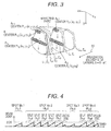
- a spot No. 1 indicates a first irradiation spot A i,1 of one layer L i
- a spot No. 2 indicates a second irradiation spot A i,2
- a spot No. 3 indicates a third irradiation spot A i,3
- a spot No. 4 indicates a fourth irradiation spot A i,4 .
- the charged particle beam irradiation system 1 sets the plurality of beam irradiation sections S k (split S k ) with respect to a part of or all the irradiation spots mentioned above (the second irradiation spot A 1,2 and the fourth irradiation spot A 1,4 in Fig. 4 ).
- the irradiation spot A i,j having the target dose R0 i,j larger than the split target dose ⁇ D0 is divided into the plurality of splits S k,j .
- the irradiation spot A i,j having the target dose R0 i,j smaller than the split target dose ⁇ D0 is not divided into the plurality of splits.
- the split target dose ⁇ D0 be 0.033 MU. Since the irradiation spot No. 1 and the irradiation spot No. 3 have the target dose R0 i,j smaller than the split target dose ⁇ D0, they are not divided into the plurality of beam irradiation sections. Since the irradiation spot No.
- the irradiation spot No. 2 and the irradiation spot No. 4 have the target dose larger than the split target dose D0, they are divided into the plurality of split S k,j .
- the irradiation spot No. 2 is divided into the excess dose and five splits S k,j i.e., (S 1,2 ) (S 2,2 ), (S 3,2 ) (S 4,2 ), and (S 5,2 ).
- the irradiation spot No. 4 is divided into the excess dose and two splits S k,j , i.e., (S 1,4 ) and (S 2,4 ).
- the respective beam irradiation sections (S 1,2 ), (S 2,2 ), (S 3,2 ), (S 4,2 ), (S 5,2 ), (S 1,4 ), and (S 2,4 ) are set to 0.033 MU.
- a beam irradiation section in which a place other than the set split S k,j is irradiated with the beam of the dose which is less than 0.033 MU is called as the excess dose.
- the irradiation spot A i,j divided into the plurality of beam irradiation sections (split) is determined based on a predetermined beam radiation dose (split target dose ⁇ D0). Specifically, in a case where the target dose R0 i,j of the irradiation spot A i,j is divided by the split target dose ⁇ D0 and the result is fewer than one, the irradiation spot A i,j is not divided into the plurality of beam irradiation sections.
- the target dose R0 i,j of the irradiation spot A i,j is divided by the split target dose ⁇ D0 and the result is one or more
- the target dose R0 i,j of the irradiation spot A i,j is divided for each predetermined beam radiation dose (split target dose ⁇ D0) so that the dose of all the beam irradiation sections becomes equal to or fewer than the predetermined beam radiation dose (split target dose ⁇ D0).
- the target position P i,j of the charged particle beam which is determined by the first scanning electromagnet 51 and the second scanning electromagnet 52 is not changed even when the beam irradiation section changes (for example, from the split (S 1,2 ) to the other split (S 2,2 )).
- the target position P i,j of the next irradiation section (S 2,2 ) remains to be the target position P i,j of the irradiation spot A i,j .
- the splits S k,j set relative to one irradiation spot A i,j are irradiated continuously with the charged particle beam.
- the irradiation spot A i,j to be divided into the plurality of beam irradiation sections S k,j is determined based on a predetermined beam radiation dose value.
- the irradiation spot A i,j may be divided into the plurality of beam irradiation sections S k,j (split S k,j ) based on a predetermined time interval instead of the predetermined beam radiation dose value.
- the irradiation spot A i,j may be divided into the beam irradiation section S k,j (split S k,j ) by equally dividing the target irradiation dose R0 i,j to the irradiation spot A i,j by using an integral quotient obtained when the target irradiation dose R0 i,j to the irradiation spot A i,j is divided by the predetermined beam radiation dose value ⁇ D0.
- Fig. 5 is a flowchart for calculating the position and the width of the charged particle beam by the charged particle beam irradiation system 1 of the present embodiment.
- Figs. 6(A) to 6(F) are diagrams of time-series timings of the beam radiation dose measurement of the charged particle beam and the calculation of the position and the width of the beam performed by the charged particle beam irradiation system 1 in the spot and each split.
- the irradiation spot No. 2 (A i,2 ) illustrated in Fig. 4 is described as an example in Figs. 6 (A) to 6 (F) .
- Fig. 6(A) indicates the measured result of the beam radiation dose by the first dose counter 64 of the beam radiation dose measuring apparatus 59
- Fig. 6(B) indicates the measured result of the beam radiation dose by the second dose counter 65 of the beam radiation dose measuring apparatus 59.
- the beam radiation dose measuring apparatus 59 outputs the spot dose satisfied signal to the central controller 62 and the irradiation controller 63. Also, as indicated in Fig.
- Fig. 6(B) when the beam radiation dose in each split reaches the target dose ⁇ D k , the beam radiation dose measuring apparatus 59 outputs the split dose satisfied signal to the irradiation controller 63.
- Fig. 6(C) is the measured result of the beam position in each split measured by the beam position measuring apparatus 58.
- Fig. 6 (D) is a timing when the beam radiation dose measuring apparatus 59 measures the beam radiation dose in each split and the beam cumulative dose in the spot and determines their normality.
- Fig. 6 (E) is a timing when the beam position measuring apparatus 58 calculates the position and the width of the beam in the split.
- Fig. 6(F) is a timing when the beam position measuring apparatus 58 calculates the position and the width of the beam in the spot and determines their normality.
- the charged particle beam irradiation system 1 starts to irradiate the irradiation spot A i,j with the charged particle beam (step S1).
- the dose monitor 54 starts to measure the beam radiation dose of the charged particle beam, and the beam position monitor 53 starts to measure the position and the width of the passing charged particle beam.
- the dose monitor 54 outputs the measured dose data to the beam radiation dose measuring apparatus 59.
- the beam radiation dose measuring apparatus 59 inputs the received dose data to the second dose counter 65, and the second dose counter 65 obtains the beam radiation dose in each split.
- the beam radiation dose measuring apparatus 59 stores information on the target dose ⁇ D k which has been previously set for each beam irradiation section S k,j (split S k,j ) in a memory (not shown).
- the beam radiation dose measuring apparatus 59 determines whether the beam radiation dose obtained by the second dose counter 65 has reached the target dose ⁇ D k (step S2). When the beam radiation dose of the beam irradiation section S k,j (split S k,j ) reaches the target dose ⁇ D k , the beam radiation dose measuring apparatus 59 outputs the split dose satisfied signal to the irradiation controller 63 and resets the count of the second dose counter 65. In this way, when the beam radiation dose measuring apparatus 59 starts to obtain the beam irradiation dose of the next beam irradiation section, the beam radiation dose measuring apparatus 59 resets the second dose counter 65 and measures the beam radiation dose from zero in the next beam irradiation section. In this way, the second dose counter 65 measures the beam radiation dose for each beam irradiation section.
- the irradiation controller 63 previously calculates the number of the split doses into which the target dose to the irradiation spot A i,j is divided and stores it in the memory (not shown).
- the irradiation controller 63 determines whether the split dose satisfied signal is the split dose satisfied signal of the final split (step S3) .
- the irradiation controller 63 does not interrupt the charged particle beam (continue the beam irradiation).
- the beam radiation dose measuring apparatus 59 calculates the position and the width of the charged particle beam of the beam irradiation section S k,j which has been most recently irradiated (step S4).
- the beam radiation dose measuring apparatus 59 determines whether the position and the width of the beam according to the calculation result are within the allowable range (step S5). When this determination departs from the allowable range, the beam radiation dose measuring apparatus 59 outputs the abnormality detected signal to the accelerator and transport system controller 61, the central controller 62, and the irradiation controller 63.
- the irradiation controller 63 terminates to irradiate with the charged particle beam (step S7) immediately or at the same time when the next split dose satisfied signal is received (step S6).
- the beam position measuring apparatus 58 does not calculate the position and the width of the charged particle beam. Accordingly, the beam radiation dose ⁇ D k of the final split and the dose ⁇ d which becomes excess when the target dose are divided by the split dose are not calculated and determined their positions and widths individually. The beam radiation dose of the final split is evaluated and determined as the cumulative dose of the whole spot after the spot irradiation has been completed.
- a value of the split dose ⁇ D0 is set so that the effect on the whole dose and dose distribution by the irradiation of the split dose ⁇ D0 does not depart from the allowable range even when an abnormality occurs in the position and the width during the irradiation of the split dose ⁇ D0.
- the charged particle beam irradiation system 1 have an interlock for interrupting or terminating the irradiation with the charged particle beam.
- the control to limit the intensity of the charged particle beam may be performed so that the next split dose is not satisfied when the position and the width of the charged particle beam which is the integration of the split dose is calculated and determined.
- the irradiating target dose for a single spot is divided into the plurality of split doses, and the beam position and the width of the charged particle beam is calculated for each split dose and determined (determination as to whether the calculation result of the beam position and the width departs from the allowable range). Then, even when an abnormality occurs in the beam position and the width of the charged particle beam during the irradiation to the single spot, it becomes possible to safely stop the beam irradiation before the influence of the abnormality departs from the allowable range. Accordingly, the limitation to the maximum dose with which the single spot can be irradiated can be considerably relaxed.
- the upper limit of the dose with which a single irradiation spot can be irradiated is relaxed, while ensuring safety.
- the number of spot determinations is reduced in which the irradiation is interrupted by reducing the number of re-paints, and a dose rate is improved.
- a charged particle beam irradiation system 1A of the present embodiment will be described.
- the charged particle beam irradiation system 1A of the present embodiment has a structure including a beam irradiation apparatus 5A instead of the beam irradiation apparatus 5 of the first embodiment.
- the description of parts, which have the same functions and are denoted with the same references as those in the configuration described in the first embodiment, is omitted.
- the beam irradiation apparatus 5A of the present embodiment will be described with reference to Fig. 7 .
- the beam irradiation apparatus 5A has a structure including two dose monitors (first dose monitor 54A and second dose monitor 54B) instead of the dose monitor 54 of the beam irradiation apparatus 5 of the first embodiment and including two beam radiation dose measuring apparatuses (first beam radiation dose measuring apparatus 59A and second beam radiation dose measuring apparatus 59B) instead of the beam radiation dose measuring apparatus 59 of the first embodiment.
- the first dose monitor 54A is connected to the first beam radiation dose measuring apparatus 59A
- the second dose monitor 54B is connected to the second beam radiation dose measuring apparatus 59B.
- the first beam radiation dose measuring apparatus 59A includes two dose counters (first dose counter 64A and second dose counter 65A).
- the second beam radiation dose measuring apparatus 59B includes two dose counters (first dose counter 64B and second dose counter 65B).
- the first dose monitor 54A and the first beam radiation dose measuring apparatus 59A are included in a first beam radiation dose measuring instrument, and the second dose monitor 54B and the second beam radiation dose measuring apparatus 59B are included in a second beam radiation dose measuring instrument.
- the first dose monitor 54A is arranged in the downstream of the second dose monitor 54B (a side of an exit of the beam irradiation apparatus 5A).
- the second dose monitor 54B may be arranged in the downstream of the first dose monitor 54A (the side of the exit of the beam irradiation apparatus 5A) .
- Figs. 8 (A) to 8 (H) are diagrams of time-series timings of the beam radiation dose measurement of the charged particle beam and the calculation of the position and the width of the beam performed by the charged particle beam irradiation system 1A in the spot and each split.
- an irradiation spot No. 2 (A i,2 ) in Fig. 4 is described as an example with reference to Figs. 8(A) to 8(H) .
- Fig. 8(A) indicates the measured result of the beam radiation dose by the first dose counter 64A of the first beam radiation dose measuring apparatus 59A
- Fig. 8(B) indicates the measured result of the beam radiation dose by the second dose counter 65A of the first beam radiation dose measuring apparatus 59A.
- the first beam radiation dose measuring apparatus 59A when the beam cumulative dose R i,j to the irradiation spot reaches the target dose R0 i,j , the first beam radiation dose measuring apparatus 59A outputs the spot dose satisfied signal to the central controller 62 and the irradiation controller 63.
- the first beam radiation dose measuring apparatus 59A outputs the split dose satisfied signal to the irradiation controller 63.
- Fig. 8(C) indicates the measured result of the beam radiation dose by the first dose counter 64B of the second beam radiation dose measuring apparatus 59B
- Fig. 8(D) indicates the measured result of the beam radiation dose by the second dose counter 65A of the beam radiation dose measuring apparatus 59B.
- Fig. 8(E) indicates a storage of beam position information in each split by a position counter (not shown) of the beam position measuring apparatus 58.
- Fig. 8(F) indicates a timing when the first beam radiation dose measuring apparatus 59A and the second beam radiation dose measuring apparatus 59B measure the beam radiation dose in each split and the beam cumulative dose in the spot.
- Fig. 8(G) indicates a timing when the beam position measuring apparatus 58 calculates the position and the width of the beam in the split, and
- Fig. 8(H) indicates a timing when the beam position measuring apparatus 58 calculates the position and the width of the beam in the spot.
- two beam radiation dose measuring instruments i.e., the first and second beam radiation dose measuring instruments, measure a dose value of the charged particle beam.
- a safer charged particle beam irradiation system can be provided by managing the beam radiation dose value by the two beam radiation dose measuring instruments.
- the irradiating target dose for a single spot is divided into the plurality of split doses, and the beam position and the width of the charged particle beam is calculated for each split dose and determined (determination as to whether the calculation result of the beam position and the width departs from the allowable range). Then, even when an abnormality occurs in the beam position and the width of the charged particle beam during the irradiation to the single spot, it becomes possible to safely stop the beam irradiation before the influence of the abnormality departs from the allowable range. Accordingly, the limitation to the maximum dose with which the single spot can be irradiated can be considerably relaxed.
- the upper limit of the dose with which a single irradiation spot can be irradiated is relaxed, while ensuring safety.
- the number of spot determinations is reduced in which the irradiation is interrupted by reducing the number of re-paints, and a dose rate is improved.
- the beam position measuring instruments (beam position monitor 53 and beam position measuring apparatus 58) obtain both the position and the width of the charged particle beam and determines the abnormality.
- one of the position and the width of the charged particle beam may be obtained and determined its abnormality.
Landscapes
- Health & Medical Sciences (AREA)
- Engineering & Computer Science (AREA)
- Biomedical Technology (AREA)
- Pathology (AREA)
- Nuclear Medicine, Radiotherapy & Molecular Imaging (AREA)
- Radiology & Medical Imaging (AREA)
- Life Sciences & Earth Sciences (AREA)
- Animal Behavior & Ethology (AREA)
- General Health & Medical Sciences (AREA)
- Public Health (AREA)
- Veterinary Medicine (AREA)
- Radiation-Therapy Devices (AREA)
Applications Claiming Priority (1)
| Application Number | Priority Date | Filing Date | Title |
|---|---|---|---|
| JP2014064969A JP6220713B2 (ja) | 2014-03-27 | 2014-03-27 | 荷電粒子ビーム照射システム |
Publications (2)
| Publication Number | Publication Date |
|---|---|
| EP2923733A1 true EP2923733A1 (de) | 2015-09-30 |
| EP2923733B1 EP2923733B1 (de) | 2018-05-02 |
Family
ID=52472245
Family Applications (1)
| Application Number | Title | Priority Date | Filing Date |
|---|---|---|---|
| EP15155323.7A Active EP2923733B1 (de) | 2014-03-27 | 2015-02-17 | Teilchenstrahlbestrahlungssystem mit geladenen Teilchen |
Country Status (5)
| Country | Link |
|---|---|
| US (1) | US9415241B2 (de) |
| EP (1) | EP2923733B1 (de) |
| JP (1) | JP6220713B2 (de) |
| CN (1) | CN104941076B (de) |
| ES (1) | ES2668465T3 (de) |
Families Citing this family (10)
| Publication number | Priority date | Publication date | Assignee | Title |
|---|---|---|---|---|
| US9839794B2 (en) * | 2014-07-14 | 2017-12-12 | Mitsubishi Electric Corporation | Particle beam therapy apparatus |
| US20160220221A1 (en) * | 2015-02-03 | 2016-08-04 | The Uab Research Foundation | Apparatuses And Methods For Determining The Beam Width Of A Computed Tomography Scanner |
| WO2017081826A1 (ja) * | 2015-11-13 | 2017-05-18 | 株式会社日立製作所 | 粒子線治療システム |
| EP3423153B1 (de) * | 2016-03-02 | 2021-05-19 | ViewRay Technologies, Inc. | Partikeltherapie mit magnetresonanzbildgebung |
| US11027151B2 (en) | 2016-03-10 | 2021-06-08 | William Beaumont Hospital | Particle arc therapy |
| JP6827730B2 (ja) | 2016-07-14 | 2021-02-10 | キヤノンメディカルシステムズ株式会社 | 放射線治療計画装置、放射線治療装置及び放射線治療計画方法 |
| US11623107B2 (en) | 2016-10-20 | 2023-04-11 | William Beaumont Hospital | Particle arc therapy |
| CN116999722A (zh) * | 2019-11-07 | 2023-11-07 | 中硼(厦门)医疗器械有限公司 | 射束照射系统及其控制方法 |
| JP7406470B2 (ja) * | 2020-08-11 | 2023-12-27 | 株式会社日立製作所 | 粒子線照射システム及びその制御方法並びに粒子線照射システムの制御装置 |
| JP7795895B2 (ja) | 2021-11-11 | 2026-01-08 | 株式会社日立ハイテク | 粒子線治療システム、照射制御装置及び照射制御方法 |
Citations (2)
| Publication number | Priority date | Publication date | Assignee | Title |
|---|---|---|---|---|
| JP2011177374A (ja) | 2010-03-02 | 2011-09-15 | Hitachi Ltd | 荷電粒子ビーム照射システム |
| US20140061498A1 (en) * | 2011-08-23 | 2014-03-06 | Mitsubishi Electric Corporation | Beam data processing apparatus and particle beam therapy system |
Family Cites Families (5)
| Publication number | Priority date | Publication date | Assignee | Title |
|---|---|---|---|---|
| EP2030650B1 (de) | 2003-05-13 | 2011-11-30 | Hitachi, Ltd. | Behandlungsplanungseinheit zur Teilchenstrahlbestrahlung |
| CN102264436B (zh) * | 2009-04-24 | 2015-07-15 | 三菱电机株式会社 | 粒子射线治疗装置 |
| CN103339529B (zh) * | 2012-01-20 | 2015-08-12 | 三菱电机株式会社 | 粒子束位置监视装置及粒子射线治疗装置 |
| JP2014028310A (ja) * | 2013-10-18 | 2014-02-13 | Mitsubishi Electric Corp | 粒子線照射システム |
| JP6692115B2 (ja) * | 2014-02-25 | 2020-05-13 | 株式会社日立製作所 | ビーム位置監視装置及び荷電粒子ビーム照射システム |
-
2014
- 2014-03-27 JP JP2014064969A patent/JP6220713B2/ja active Active
-
2015
- 2015-02-16 CN CN201510085293.2A patent/CN104941076B/zh active Active
- 2015-02-17 ES ES15155323.7T patent/ES2668465T3/es active Active
- 2015-02-17 EP EP15155323.7A patent/EP2923733B1/de active Active
- 2015-02-19 US US14/625,662 patent/US9415241B2/en active Active
Patent Citations (2)
| Publication number | Priority date | Publication date | Assignee | Title |
|---|---|---|---|---|
| JP2011177374A (ja) | 2010-03-02 | 2011-09-15 | Hitachi Ltd | 荷電粒子ビーム照射システム |
| US20140061498A1 (en) * | 2011-08-23 | 2014-03-06 | Mitsubishi Electric Corporation | Beam data processing apparatus and particle beam therapy system |
Non-Patent Citations (1)
| Title |
|---|
| KOJI MATSUDA ET AL: "World-first Proton Pencil Beam Scanning System with FDA Clearance -Completion of Proton Therapy System for MDACC-", HITACHI REVIEW, vol. 58, no. 5, 1 January 2009 (2009-01-01), pages 225 - 232, XP055167652 * |
Also Published As
| Publication number | Publication date |
|---|---|
| EP2923733B1 (de) | 2018-05-02 |
| US9415241B2 (en) | 2016-08-16 |
| ES2668465T3 (es) | 2018-05-18 |
| JP2015186536A (ja) | 2015-10-29 |
| JP6220713B2 (ja) | 2017-10-25 |
| CN104941076A (zh) | 2015-09-30 |
| US20150273241A1 (en) | 2015-10-01 |
| CN104941076B (zh) | 2018-03-30 |
Similar Documents
| Publication | Publication Date | Title |
|---|---|---|
| US9415241B2 (en) | Charged particle beam irradiation system | |
| JP6692115B2 (ja) | ビーム位置監視装置及び荷電粒子ビーム照射システム | |
| US8299448B2 (en) | Determination of control parameters for irradiation of a moving target volume in a body | |
| US9061143B2 (en) | Charged particle beam irradiation system and charged particle beam irradiation planning method | |
| JP5409428B2 (ja) | 荷電粒子照射システム及び照射計画装置 | |
| JP5496414B2 (ja) | 粒子線治療装置 | |
| US9750957B2 (en) | System for irradiating charged particles and method for irradiating charged particles | |
| US20100117002A1 (en) | Irradiation System and Irradiation Method | |
| US9265970B2 (en) | Particle beam irradiation system | |
| JP6527241B2 (ja) | 粒子線治療システム | |
| JP5193132B2 (ja) | 荷電粒子ビーム照射システム | |
| US9937361B2 (en) | Particle beam irradiation apparatus | |
| JP2015536770A (ja) | 標的体積の動きを考慮に入れた粒子線照射の照射計画 | |
| US9839794B2 (en) | Particle beam therapy apparatus | |
| CN107427694A (zh) | 带电粒子束治疗装置 | |
| JP6484683B2 (ja) | 荷電粒子ビーム照射システム | |
| JP6494808B2 (ja) | 粒子線治療装置 | |
| JP2013138774A (ja) | 放射線治療システム | |
| JP7539629B2 (ja) | 治療計画装置、粒子線治療システム及びコンピュータプログラム |
Legal Events
| Date | Code | Title | Description |
|---|---|---|---|
| PUAI | Public reference made under article 153(3) epc to a published international application that has entered the european phase |
Free format text: ORIGINAL CODE: 0009012 |
|
| 17P | Request for examination filed |
Effective date: 20150417 |
|
| AK | Designated contracting states |
Kind code of ref document: A1 Designated state(s): AL AT BE BG CH CY CZ DE DK EE ES FI FR GB GR HR HU IE IS IT LI LT LU LV MC MK MT NL NO PL PT RO RS SE SI SK SM TR |
|
| AX | Request for extension of the european patent |
Extension state: BA ME |
|
| 17Q | First examination report despatched |
Effective date: 20160726 |
|
| STAA | Information on the status of an ep patent application or granted ep patent |
Free format text: STATUS: EXAMINATION IS IN PROGRESS |
|
| GRAP | Despatch of communication of intention to grant a patent |
Free format text: ORIGINAL CODE: EPIDOSNIGR1 |
|
| STAA | Information on the status of an ep patent application or granted ep patent |
Free format text: STATUS: GRANT OF PATENT IS INTENDED |
|
| INTG | Intention to grant announced |
Effective date: 20171213 |
|
| GRAS | Grant fee paid |
Free format text: ORIGINAL CODE: EPIDOSNIGR3 |
|
| GRAA | (expected) grant |
Free format text: ORIGINAL CODE: 0009210 |
|
| STAA | Information on the status of an ep patent application or granted ep patent |
Free format text: STATUS: THE PATENT HAS BEEN GRANTED |
|
| AK | Designated contracting states |
Kind code of ref document: B1 Designated state(s): AL AT BE BG CH CY CZ DE DK EE ES FI FR GB GR HR HU IE IS IT LI LT LU LV MC MK MT NL NO PL PT RO RS SE SI SK SM TR |
|
| REG | Reference to a national code |
Ref country code: GB Ref legal event code: FG4D |
|
| REG | Reference to a national code |
Ref country code: CH Ref legal event code: EP Ref country code: AT Ref legal event code: REF Ref document number: 994567 Country of ref document: AT Kind code of ref document: T Effective date: 20180515 |
|
| REG | Reference to a national code |
Ref country code: ES Ref legal event code: FG2A Ref document number: 2668465 Country of ref document: ES Kind code of ref document: T3 Effective date: 20180518 |
|
| REG | Reference to a national code |
Ref country code: DE Ref legal event code: R096 Ref document number: 602015010554 Country of ref document: DE Ref country code: IE Ref legal event code: FG4D |
|
| REG | Reference to a national code |
Ref country code: NL Ref legal event code: MP Effective date: 20180502 |
|
| REG | Reference to a national code |
Ref country code: LT Ref legal event code: MG4D |
|
| PG25 | Lapsed in a contracting state [announced via postgrant information from national office to epo] |
Ref country code: BG Free format text: LAPSE BECAUSE OF FAILURE TO SUBMIT A TRANSLATION OF THE DESCRIPTION OR TO PAY THE FEE WITHIN THE PRESCRIBED TIME-LIMIT Effective date: 20180802 Ref country code: FI Free format text: LAPSE BECAUSE OF FAILURE TO SUBMIT A TRANSLATION OF THE DESCRIPTION OR TO PAY THE FEE WITHIN THE PRESCRIBED TIME-LIMIT Effective date: 20180502 Ref country code: NO Free format text: LAPSE BECAUSE OF FAILURE TO SUBMIT A TRANSLATION OF THE DESCRIPTION OR TO PAY THE FEE WITHIN THE PRESCRIBED TIME-LIMIT Effective date: 20180802 Ref country code: SE Free format text: LAPSE BECAUSE OF FAILURE TO SUBMIT A TRANSLATION OF THE DESCRIPTION OR TO PAY THE FEE WITHIN THE PRESCRIBED TIME-LIMIT Effective date: 20180502 Ref country code: LT Free format text: LAPSE BECAUSE OF FAILURE TO SUBMIT A TRANSLATION OF THE DESCRIPTION OR TO PAY THE FEE WITHIN THE PRESCRIBED TIME-LIMIT Effective date: 20180502 |
|
| PG25 | Lapsed in a contracting state [announced via postgrant information from national office to epo] |
Ref country code: LV Free format text: LAPSE BECAUSE OF FAILURE TO SUBMIT A TRANSLATION OF THE DESCRIPTION OR TO PAY THE FEE WITHIN THE PRESCRIBED TIME-LIMIT Effective date: 20180502 Ref country code: RS Free format text: LAPSE BECAUSE OF FAILURE TO SUBMIT A TRANSLATION OF THE DESCRIPTION OR TO PAY THE FEE WITHIN THE PRESCRIBED TIME-LIMIT Effective date: 20180502 Ref country code: HR Free format text: LAPSE BECAUSE OF FAILURE TO SUBMIT A TRANSLATION OF THE DESCRIPTION OR TO PAY THE FEE WITHIN THE PRESCRIBED TIME-LIMIT Effective date: 20180502 Ref country code: NL Free format text: LAPSE BECAUSE OF FAILURE TO SUBMIT A TRANSLATION OF THE DESCRIPTION OR TO PAY THE FEE WITHIN THE PRESCRIBED TIME-LIMIT Effective date: 20180502 Ref country code: GR Free format text: LAPSE BECAUSE OF FAILURE TO SUBMIT A TRANSLATION OF THE DESCRIPTION OR TO PAY THE FEE WITHIN THE PRESCRIBED TIME-LIMIT Effective date: 20180803 |
|
| REG | Reference to a national code |
Ref country code: AT Ref legal event code: MK05 Ref document number: 994567 Country of ref document: AT Kind code of ref document: T Effective date: 20180502 |
|
| PG25 | Lapsed in a contracting state [announced via postgrant information from national office to epo] |
Ref country code: RO Free format text: LAPSE BECAUSE OF FAILURE TO SUBMIT A TRANSLATION OF THE DESCRIPTION OR TO PAY THE FEE WITHIN THE PRESCRIBED TIME-LIMIT Effective date: 20180502 Ref country code: DK Free format text: LAPSE BECAUSE OF FAILURE TO SUBMIT A TRANSLATION OF THE DESCRIPTION OR TO PAY THE FEE WITHIN THE PRESCRIBED TIME-LIMIT Effective date: 20180502 Ref country code: AT Free format text: LAPSE BECAUSE OF FAILURE TO SUBMIT A TRANSLATION OF THE DESCRIPTION OR TO PAY THE FEE WITHIN THE PRESCRIBED TIME-LIMIT Effective date: 20180502 Ref country code: EE Free format text: LAPSE BECAUSE OF FAILURE TO SUBMIT A TRANSLATION OF THE DESCRIPTION OR TO PAY THE FEE WITHIN THE PRESCRIBED TIME-LIMIT Effective date: 20180502 Ref country code: CZ Free format text: LAPSE BECAUSE OF FAILURE TO SUBMIT A TRANSLATION OF THE DESCRIPTION OR TO PAY THE FEE WITHIN THE PRESCRIBED TIME-LIMIT Effective date: 20180502 Ref country code: SK Free format text: LAPSE BECAUSE OF FAILURE TO SUBMIT A TRANSLATION OF THE DESCRIPTION OR TO PAY THE FEE WITHIN THE PRESCRIBED TIME-LIMIT Effective date: 20180502 Ref country code: PL Free format text: LAPSE BECAUSE OF FAILURE TO SUBMIT A TRANSLATION OF THE DESCRIPTION OR TO PAY THE FEE WITHIN THE PRESCRIBED TIME-LIMIT Effective date: 20180502 |
|
| REG | Reference to a national code |
Ref country code: DE Ref legal event code: R097 Ref document number: 602015010554 Country of ref document: DE |
|
| PG25 | Lapsed in a contracting state [announced via postgrant information from national office to epo] |
Ref country code: SM Free format text: LAPSE BECAUSE OF FAILURE TO SUBMIT A TRANSLATION OF THE DESCRIPTION OR TO PAY THE FEE WITHIN THE PRESCRIBED TIME-LIMIT Effective date: 20180502 |
|
| PLBE | No opposition filed within time limit |
Free format text: ORIGINAL CODE: 0009261 |
|
| STAA | Information on the status of an ep patent application or granted ep patent |
Free format text: STATUS: NO OPPOSITION FILED WITHIN TIME LIMIT |
|
| 26N | No opposition filed |
Effective date: 20190205 |
|
| PG25 | Lapsed in a contracting state [announced via postgrant information from national office to epo] |
Ref country code: SI Free format text: LAPSE BECAUSE OF FAILURE TO SUBMIT A TRANSLATION OF THE DESCRIPTION OR TO PAY THE FEE WITHIN THE PRESCRIBED TIME-LIMIT Effective date: 20180502 |
|
| REG | Reference to a national code |
Ref country code: CH Ref legal event code: PL |
|
| PG25 | Lapsed in a contracting state [announced via postgrant information from national office to epo] |
Ref country code: MC Free format text: LAPSE BECAUSE OF FAILURE TO SUBMIT A TRANSLATION OF THE DESCRIPTION OR TO PAY THE FEE WITHIN THE PRESCRIBED TIME-LIMIT Effective date: 20180502 Ref country code: LU Free format text: LAPSE BECAUSE OF NON-PAYMENT OF DUE FEES Effective date: 20190217 |
|
| REG | Reference to a national code |
Ref country code: BE Ref legal event code: MM Effective date: 20190228 |
|
| REG | Reference to a national code |
Ref country code: IE Ref legal event code: MM4A |
|
| PG25 | Lapsed in a contracting state [announced via postgrant information from national office to epo] |
Ref country code: AL Free format text: LAPSE BECAUSE OF FAILURE TO SUBMIT A TRANSLATION OF THE DESCRIPTION OR TO PAY THE FEE WITHIN THE PRESCRIBED TIME-LIMIT Effective date: 20180502 |
|
| PG25 | Lapsed in a contracting state [announced via postgrant information from national office to epo] |
Ref country code: LI Free format text: LAPSE BECAUSE OF NON-PAYMENT OF DUE FEES Effective date: 20190228 Ref country code: CH Free format text: LAPSE BECAUSE OF NON-PAYMENT OF DUE FEES Effective date: 20190228 |
|
| PG25 | Lapsed in a contracting state [announced via postgrant information from national office to epo] |
Ref country code: IE Free format text: LAPSE BECAUSE OF NON-PAYMENT OF DUE FEES Effective date: 20190217 |
|
| PG25 | Lapsed in a contracting state [announced via postgrant information from national office to epo] |
Ref country code: BE Free format text: LAPSE BECAUSE OF NON-PAYMENT OF DUE FEES Effective date: 20190228 |
|
| PG25 | Lapsed in a contracting state [announced via postgrant information from national office to epo] |
Ref country code: TR Free format text: LAPSE BECAUSE OF FAILURE TO SUBMIT A TRANSLATION OF THE DESCRIPTION OR TO PAY THE FEE WITHIN THE PRESCRIBED TIME-LIMIT Effective date: 20180502 |
|
| PG25 | Lapsed in a contracting state [announced via postgrant information from national office to epo] |
Ref country code: MT Free format text: LAPSE BECAUSE OF NON-PAYMENT OF DUE FEES Effective date: 20190217 Ref country code: PT Free format text: LAPSE BECAUSE OF FAILURE TO SUBMIT A TRANSLATION OF THE DESCRIPTION OR TO PAY THE FEE WITHIN THE PRESCRIBED TIME-LIMIT Effective date: 20180903 |
|
| PG25 | Lapsed in a contracting state [announced via postgrant information from national office to epo] |
Ref country code: CY Free format text: LAPSE BECAUSE OF FAILURE TO SUBMIT A TRANSLATION OF THE DESCRIPTION OR TO PAY THE FEE WITHIN THE PRESCRIBED TIME-LIMIT Effective date: 20180502 |
|
| PG25 | Lapsed in a contracting state [announced via postgrant information from national office to epo] |
Ref country code: IS Free format text: LAPSE BECAUSE OF FAILURE TO SUBMIT A TRANSLATION OF THE DESCRIPTION OR TO PAY THE FEE WITHIN THE PRESCRIBED TIME-LIMIT Effective date: 20180902 |
|
| PG25 | Lapsed in a contracting state [announced via postgrant information from national office to epo] |
Ref country code: HU Free format text: LAPSE BECAUSE OF FAILURE TO SUBMIT A TRANSLATION OF THE DESCRIPTION OR TO PAY THE FEE WITHIN THE PRESCRIBED TIME-LIMIT; INVALID AB INITIO Effective date: 20150217 |
|
| PG25 | Lapsed in a contracting state [announced via postgrant information from national office to epo] |
Ref country code: MK Free format text: LAPSE BECAUSE OF FAILURE TO SUBMIT A TRANSLATION OF THE DESCRIPTION OR TO PAY THE FEE WITHIN THE PRESCRIBED TIME-LIMIT Effective date: 20180502 |
|
| REG | Reference to a national code |
Ref country code: DE Ref legal event code: R081 Ref document number: 602015010554 Country of ref document: DE Owner name: HITACHI HIGH-TECH CORPORATION, JP Free format text: FORMER OWNER: HITACHI, LTD., TOKYO, JP |
|
| REG | Reference to a national code |
Ref country code: GB Ref legal event code: 732E Free format text: REGISTERED BETWEEN 20240711 AND 20240717 |
|
| REG | Reference to a national code |
Ref country code: ES Ref legal event code: PC2A Owner name: HITACHI HIGH-TECH CORPORATION Effective date: 20241106 |
|
| PGFP | Annual fee paid to national office [announced via postgrant information from national office to epo] |
Ref country code: GB Payment date: 20260122 Year of fee payment: 12 |
|
| PGFP | Annual fee paid to national office [announced via postgrant information from national office to epo] |
Ref country code: ES Payment date: 20260302 Year of fee payment: 12 |
|
| PGFP | Annual fee paid to national office [announced via postgrant information from national office to epo] |
Ref country code: DE Payment date: 20260121 Year of fee payment: 12 |
|
| PGFP | Annual fee paid to national office [announced via postgrant information from national office to epo] |
Ref country code: IT Payment date: 20260121 Year of fee payment: 12 |
|
| PGFP | Annual fee paid to national office [announced via postgrant information from national office to epo] |
Ref country code: FR Payment date: 20260121 Year of fee payment: 12 |