EP2923046B1 - Brennkraftmaschine mit zwei wartungsseiten - Google Patents
Brennkraftmaschine mit zwei wartungsseiten Download PDFInfo
- Publication number
- EP2923046B1 EP2923046B1 EP13795161.2A EP13795161A EP2923046B1 EP 2923046 B1 EP2923046 B1 EP 2923046B1 EP 13795161 A EP13795161 A EP 13795161A EP 2923046 B1 EP2923046 B1 EP 2923046B1
- Authority
- EP
- European Patent Office
- Prior art keywords
- internal combustion
- combustion engine
- crankcase
- oil
- engine according
- Prior art date
- Legal status (The legal status is an assumption and is not a legal conclusion. Google has not performed a legal analysis and makes no representation as to the accuracy of the status listed.)
- Active
Links
Images







Classifications
-
- F—MECHANICAL ENGINEERING; LIGHTING; HEATING; WEAPONS; BLASTING
- F01—MACHINES OR ENGINES IN GENERAL; ENGINE PLANTS IN GENERAL; STEAM ENGINES
- F01M—LUBRICATING OF MACHINES OR ENGINES IN GENERAL; LUBRICATING INTERNAL COMBUSTION ENGINES; CRANKCASE VENTILATING
- F01M11/00—Component parts, details or accessories, not provided for in, or of interest apart from, groups F01M1/00 - F01M9/00
- F01M11/02—Arrangements of lubricant conduits
-
- F—MECHANICAL ENGINEERING; LIGHTING; HEATING; WEAPONS; BLASTING
- F01—MACHINES OR ENGINES IN GENERAL; ENGINE PLANTS IN GENERAL; STEAM ENGINES
- F01M—LUBRICATING OF MACHINES OR ENGINES IN GENERAL; LUBRICATING INTERNAL COMBUSTION ENGINES; CRANKCASE VENTILATING
- F01M11/00—Component parts, details or accessories, not provided for in, or of interest apart from, groups F01M1/00 - F01M9/00
- F01M11/03—Mounting or connecting of lubricant purifying means relative to the machine or engine; Details of lubricant purifying means
-
- F—MECHANICAL ENGINEERING; LIGHTING; HEATING; WEAPONS; BLASTING
- F01—MACHINES OR ENGINES IN GENERAL; ENGINE PLANTS IN GENERAL; STEAM ENGINES
- F01M—LUBRICATING OF MACHINES OR ENGINES IN GENERAL; LUBRICATING INTERNAL COMBUSTION ENGINES; CRANKCASE VENTILATING
- F01M1/00—Pressure lubrication
- F01M1/10—Lubricating systems characterised by the provision therein of lubricant venting or purifying means, e.g. of filters
- F01M2001/105—Lubricating systems characterised by the provision therein of lubricant venting or purifying means, e.g. of filters characterised by the layout of the purification arrangements
- F01M2001/1092—Lubricating systems characterised by the provision therein of lubricant venting or purifying means, e.g. of filters characterised by the layout of the purification arrangements comprising valves bypassing the filter
-
- F—MECHANICAL ENGINEERING; LIGHTING; HEATING; WEAPONS; BLASTING
- F02—COMBUSTION ENGINES; HOT-GAS OR COMBUSTION-PRODUCT ENGINE PLANTS
- F02F—CYLINDERS, PISTONS OR CASINGS, FOR COMBUSTION ENGINES; ARRANGEMENTS OF SEALINGS IN COMBUSTION ENGINES
- F02F7/00—Casings, e.g. crankcases
- F02F7/0065—Shape of casings for other machine parts and purposes, e.g. utilisation purposes, safety
- F02F7/0073—Adaptations for fitting the engine, e.g. front-plates or bell-housings
- F02F2007/0075—Front covers
Definitions
- the invention relates to an internal combustion engine with two maintenance sides.
- an internal combustion engine which has at least one crankshaft and a crankcase supporting the crankshaft, the crankcase in particular as a raw part having at least two oil filter surfaces on opposite sides of the crankcase.
- the advantage here is that, depending on the installation situation, one or the other side of the crankcase can be used as the maintenance side.
- the cylinder crankcase already contains an oil filter surface, an oil dipstick hole surface, an oil filler neck and an exhaust gas turbocharger connection surface on both possible maintenance sides as a raw part.
- the desired maintenance side is generated from these connection surfaces by optional machining in conjunction with the corresponding closure parts.
- the channels in the side part transport the oil that is released from the oil pump z. B. is pumped for exhaust gas turbocharger lubrication.
- the front oil supply openings are tightly closed by means of the side part, and the oil supply is then carried out according to the respective oil scheme.
- the internal combustion engine has at least one side part that can be tightly connected to it along an end face of the crankcase and extends, the side part having at least one connecting line between the main and / or secondary oil duct.
- the channels are preferably manufactured using the casting process, they are open on one side and are closed by being attached to the crankcase and are then sealed.
- the connecting line is created by the sealingly connecting side part with the end face, whereby the line can only be arranged in the crankcase or half as a corresponding half-shell in the crankcase and half in the side part in such a way that said by connecting the side part to the end face of the crankcase Connection line is created (as is the case with Figures 3 and 4th is made clear).
- the advantage is the high flexibility with regard to the choice of the selected maintenance side.
- the connecting line arranged at the end has at least one oil pressure regulating valve and the oil pressure regulating valve advantageously diverts the excess amount of oil into the oil sump via integrated channels or bores.
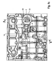
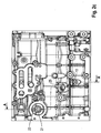
- FIG 1c the right maintenance side of a crankcase 1 of an internal combustion engine is shown.
- the right-hand turbocharger port 14 is located at approximately the same height as the oil filter surface 2
- Oil filter surface 2 and the right ATL connection 14 runs the supply line of the ATL 16, which delivers sufficient amounts of oil to the ATL.
- the right oil filler neck 4 is also located below the ATL connection 14 on the same maintenance side.
- the right oil filler neck 4 is located approximately in the middle of the right maintenance side of the crankcase 1 below the right oil filler neck 4 Dipstick or the right dipstick hole.
- the main oil duct 6 and the supply line of the cylinder head 17 can be seen on the end face 18.
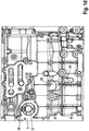
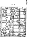
- the Figure 2 shows the left maintenance side of a crankcase 1 of an internal combustion engine.
- the oil filter surface 3 that is suitable for receiving the oil filter.
- the left turbo-charger connection 14 Oil filter surface 3 and the left turbocharger connection 14 runs the main oil duct 6, which conveys oil to the turbocharger.
- the left oil filler neck 5 is also located below the ATL connection 15 on the same maintenance side.
- the left dipstick 13 or the left dipstick hole is located.
- the main oil duct 6 and the supply line of the cylinder head 17 are arranged on the end face 18.
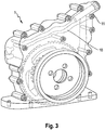
- Figure 3 represents the end face of the crankcase 1 of the internal combustion engine.
- the transverse connecting line 10 can be seen, which results from the sealing connection of the side part 9 with the end face of the crankcase 1.
- An oil pressure valve 11 is arranged in the connecting line 10.
- Figure 5c shows the side part 9 installed on the end face 18 of the crankcase 1 by means of screws 19 from the front.
- the oil pressure regulating valve 11 is arranged as part of the connecting line 10.
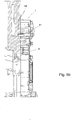
- the DD view can be found in Figure 5b again.
- the EE view is displayed in Figure 5d shown.
- Figure 6b shows the oil scheme for the case that the maintenance side is arranged on the left side of the crankcase 1.
Landscapes
- Engineering & Computer Science (AREA)
- Mechanical Engineering (AREA)
- General Engineering & Computer Science (AREA)
- Lubrication Details And Ventilation Of Internal Combustion Engines (AREA)
Description
- Die Erfindung betrifft eine Brennkraftmaschine mit zwei Wartungsseiten.
- Derartige Brennkraftmaschinen sind bekannt, z. B. aus der
DE 197 19 199 . Hierbei ist von Nachteil, dass der dort offenbarte Kraftfahrzeugmotor keine zwei Wartungsseiten offenbart, was die Anzahl an Einbauvarianten stark einschränkt. Eine Brennkraftmaschine mit Ölfiltern auf zwei Seiten wird in derUS 2006/0231060 A1 offenbart. - Es ist die Aufgabe der vorliegenden Erfindung, die oben genannten Nachteile zu vermeiden und eine Brennkraftmaschine zu schaffen, die wenigstens zwei Wartungsseiten aufweist.
- Die Aufgabe wird gelöst durch eine Brennkraftmaschine, die wenigstens eine Kurbelwelle und ein die Kurbelwelle abstützendes Kurbelgehäuse aufweist, wobei das Kurbelgehäuse insbesondere als Rohteil wenigstens zwei Ölfilterflächen an gegenüberliegenden Seiten des Kurbelgehäuses aufweist.
- Hierbei ist von Vorteil, dass in Abhängigkeit der Einbausituation die eine oder die andere Seite des Kurbelgehäuses als Wartungsseite Verwendung finden kann. Das Zylinderkurbelgehäuse enthält bereits als Rohteil auf beiden möglichen Wartungsseiten je eine Ölfilterfläche, eine Ölpeilstabbohrungsfläche, einen Öleinfüllstutzen sowie eine Abgasturboladeranschlussfläche. Aus diesen Anschlussflächen wird durch wahlweise Bearbeitung in Verbindung mit den korrespondierenden Verschlussteilen die gewünschte Wartungsseite erzeugt. Es wird sowohl die Ölzu- als auch die Ölrücklaufleitung - für den Fall, dass die rechte die Wartungsseite sein soll - zu dem rechten Ölfilter über den vorderen Wellendichtringträger, der nachfolgend als Seitenteil bezeichnet wird, erfolgen. Die Kanäle im Seitenteil transportieren das Öl, das von der Ölpumpe z. B. zur Abgasturbolader-Schmierung gepumpt wird. Soll die Wartungsseite jedoch auf der linken Seite liegen, dann werden die stirnseitigen Ölversorgungsöffnungen mittels des Seitenteils dicht verschlossen, die Ölversorgung geschieht dann gemäß dem jeweiligen Ölschema.
- Eine weitere erfindungsgemäße Weiterbildung sieht vor, dass die Brennkraftmaschine wenigstens ein sich entlang einer Stirnseite des Kurbelgehäuses daran dicht anschließbares und erstreckendes Seitenteil aufweist, wobei das Seitenteil wenigstens eine Verbindungsleitung zwischen Haupt- und/oder Nebenölkanal aufweist. Die Kanäle (Haupt- oder Nebenkanal) werden vorzugsweise im Gussverfahren hergestellt, sie sind einseitig offen und werden durch den Anbau an das Kurbelgehäuse geschlossen und sind dann abgedichtet. Die Verbindungsleitung entsteht durch das dichtend verbindende Seitenteil mit der Stirnseite, wobei die Leitung lediglich im Kurbelgehäuse angeordnet sein kann oder je zur Hälfte als korrespondierende Halbschale im Kurbelgehäuse und in dem Seitenteil in der Weise, dass durch das Verbinden des Seitenteils mit der Stirnseite des Kurbelgehäuses besagte Verbindungsleitung entsteht (wie dies durch die
Figuren 3 und4 verdeutlicht wird). Der Vorteil besteht in der hohen Flexibilität bezüglich der Wahlmöglichkeit der gewählten Wartungsseite. - Eine andere vorteilhafte Weiterbildung sieht vor, dass die stirnseitig angeordnete Verbindungsleitung wenigstens ein Öldruckregelventil aufweist und das Öldruckregelventil vorteilhafterweise die überschüssige Ölmenge in den Ölsumpf über integrierte Kanäle bzw. Bohrungen absteuert.
- Weitere Vorteile finden sich in den Unteransprüchen.
- Nachfolgend wird die Erfindung anhand eines bevorzugten Ausführungsbeispiels dargestellt, es zeigen:
- Figur 1a
- die Stirnseite des Kurbelgehäuses, im Falle Wartungsseite rechts
- Figur 1b
- stirnseitiger Schnitt B-B des Kurbelgehäuses, im Falle Wartungsseite rechts
- Figur 1c
- Wartungsseite rechts
- Figur 1d
- die linke Seite des Kurbelgehäuses, im Falle Wartungsseite rechts
- Figur 2
- die linke Wartungsseite des Kurbelgehäuses aus
Figur 1 - Figur 2a
- Stirnseite des Kurbelgehäuses, im Falle Wartungsseite links
- Figur 2b
- stirnseitiger Schnitt AA des Kurbelgehäuses, im Falle Wartungsseite links
- Figur 2c
- Wartungsseite links des Kurbelgehäuses
- Figur 2d
- unbearbeitete rechte Seite des Kurbelgehäuses, im Falle Wartungsseite links
- Figur 3
- die Stirnseite des Kurbelgehäuses aus
Figur 1 - Figur 4
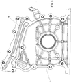
- das Seitenteil, das an der Stirnseite aus
Figur 3 verbaut wird - Figur 5a
- das an der Stirnseite verbaute Seitenteil von schräg vorne
- Figur 5b
- das an der Stirnseite verbaute Seitenteil von der Seite
- Figur 5c
- das an der Stirnseite verbaute Seitenteil von vorne
- Figur 6a
- das Ölschema, im Falle Wartungsseite rechts
- Figur 6b
- das Ölschema, im Falle Wartungsseite links
- Figur 6c
- den Ölkreislauf
- In
Figur 1c wird die rechte Wartungsseite eines Kurbelgehäuses 1 einer Brennkraftmaschine dargestellt. In unmittelbarer Nähe zur Stirnseite 18 des Kurbelgehäuses 1 befindet sich auf der rechten Wartungsseite des Kurbelgehäuses 1 die zur Aufnahme des Ölfilters geeignete Ölfilterfläche 2. Auf etwa gleicher Höhe wie die Ölfilterfläche 2 befindet sich der rechte ATL-Anschluss 14. Im Kurbelgehäuse 1 und hinter der Ölfilterfläche 2 und dem rechten ATL-Anschluss 14 verläuft die Versorgungsleitung des ATL 16, die ausreichende Mengen Öl zum ATL fördert. Unterhalb des ATL-Anschlusses 14 befindet sich ebenfalls auf der gleichen Wartungsseite der rechte Öleinfüllstutzen 4. In etwa der Mitte der rechten Wartungsseite des Kurbelgehäuses 1 befindet sich unterhalb des rechten Öleinfüllstutzens 4 der rechte Peilstab bzw. die rechte Peilstabbohrung. Auf der Stirnseite 18 sind der Hauptölkanal 6 und die Versorgungsleitung des Zylinderkopfs 17 zu sehen. - Die
Figur 2 zeigt die linke Wartungsseite eines Kurbelgehäuses 1 einer Brennkraftmaschine. In unmittelbarer Nähe zur Stirnseite 18 des Kurbelgehäuses 1 befindet sich auf der linken Wartungsseite des Kurbelgehäuses 1 die zur Aufnahme des Ölfilters geeignete Ölfilterfläche 3. Auf etwa gleicher Höhe wie die Ölfilterfläche 3 befindet sich der linke ATL-Anschluss 14. Im Kurbelgehäuse 1 und hinter der Ölfilterfläche 3 und dem linken ATL-Anschluss 14 verläuft der Hauptölkanal 6, der Öl zum ATL fördert. Unterhalb des ATL-Anschlusses 15 befindet sich ebenfalls auf der gleichen Wartungsseite der linke Öleinfüllstutzen 5. In etwa der Mitte der linken Wartungsseite des Kurbelgehäuses 1 befindet sich unterhalb des linken Öleinfüllstutzens 5 der linke Peilstab 13 bzw. die linke Peilstabbohrung. Auf der Stirnseite 18 sind der Hauptölkanal 6 und die Versorgungsleitung des Zylinderkopfs 17 angeordnet. -
Figur 3 stellt die Stirnseite des Kurbelgehäuses 1 der Brennkraftmaschine dar. Im oberen Bereich des Kurbelgehäuses 1 ist die quer verlaufende Verbindungsleitung 10 zu sehen, die sich aus der dichtenden Verbindung von Seitenteil 9 mit der Stirnseite des Kurbelgehäuses 1 ergibt. In der Verbindungsleitung 10 ist ein Öldruckventil 11 angeordnet. - In
Figur 4 wird das stirnseitig an das Kurbelgehäuses 1 der Brennkraftmaschine anzuordnende Seitenteil 9 dargestellt. Im oberen Bereich des Kurbelgehäuses 1 ist die quer verlaufende Verbindungsleitung 10 zu sehen, die sich aus der dichtenden Verbindung von Seitenteil 9 mit der Stirnseite des Kurbelgehäuses 1 ergibt. In der Verbindungsleitung 10 ist ein Öldruckventil 11 angeordnet. - In der
Figur 5a wird das an der Stirnseite 18 des Kurbelgehäuses 1 mittels Schrauben 19 verbaute Seitenteil 9 von schräg vorne gezeigt. An der oberen rechten Seite des Seitenteils 9 ist das Öldruckregelventil 11 als Bestandteil der Verbindungsleitung 10 angeordnet. - In der
Figur 5b wird das an der Stirnseite 18 des Kurbelgehäuses 1 mittels Schrauben 19 verbaute Seitenteil 9 in der Ansicht D-D von der rechten Seite gezeigt. An der oberen rechten Seite des Seitenteils 9 ist das Öldruckregelventil 11 als Bestandteil der Verbindungsleitung 10 angeordnet. -
Figur 5c zeigt das an der Stirnseite 18 des Kurbelgehäuses 1 mittels Schrauben 19 verbaute Seitenteil 9 von vorne. An der oberen rechten Seite des Seitenteils 9 ist das Öldruckregelventil 11 als Bestandteil der Verbindungsleitung 10 angeordnet. Die Ansicht D-D findet sich inFigur 5b wieder. - Die Ansicht E-E wird in
Figur 5d dargestellt. - In
Figur 5d wird das an der Stirnseite 18 des Kurbelgehäuses 1 mittels Schrauben 19 verbaute Seitenteil 9 in der Ansicht D-D von der rechten Seite dargestellt. An der oberen rechten Seite des Seitenteils 9 ist das ÖIdruckregelventil 11 als Bestandteil der Verbindungsleitung 10 angeordnet. - In
Figur 6a wird das Ölschema für den Fall gezeigt, dass die Wartungsseite rechts angeordnet ist. -
Figur 6b zeigt das Ölschema für den Fall, dass die Wartungsseite auf der linken Seite des Kurbelgehäuses 1 angeordnet ist. - In
Figur 6c wird der Ölkreislauf ohne das umgebende Kurbelgehäuse dargestellt, wie es vom Hauptölkanal 6 z. B. die Ölfilterflächen 2, 3 verbindet. -
- 1
- Kurbelgehäuse
- 2
- rechte Ölfilterfläche
- 3
- linke Ölfilterfläche
- 4
- rechter Öleinfüllstutzen
- 5
- linker Öleinfüllstutzen
- 6
- Hauptölkanal
- 7
- Ölzuleitung
- 8
- Ölrücklaufleitung
- 9
- Seitenteil
- 10
- Verbindungsleitung
- 11
- Öldruckregelventil
- 12
- rechte Ölpeilstabbohrung
- 13
- linke Ölpeilstabbohrung
- 14
- rechter Abgasturboladeranschluss
- 15
- linker Abgasturboladeranschluss
- 16
- Versorgungsleitung des ATL
- 17
- Versorgungsleitung Zylinderkopf
- 18
- Stirnseite
- 19
- Schrauben
- 20
- Filterzulauf nicht bearbeitet
- 21
- Filterablauf bearbeitet, links
- 22
- Filterzulauf unbearbeitet, aber offen, links
- 23
- Filterzulauf nicht bearbeitet, rechts
- 24
- Filterablauf nicht bearbeitet, rechts
- 25
- Öleinfüllstutzen bearbeitet, links
- 26
- Öleinfüllstutzen nicht bearbeitet, rechts
- 27
- Ölpeilstab nicht bearbeitet, rechts
- 28
- Filterzulauf bearbeitet, rechts
- 29
- Filterzulauf wg. Verschlussschraube bearbeitet
- 30
- Filterablauf nicht bearbeitet
- 31
- Öleinfüllstutzen nicht bearbeitet
- 32
- Filterzulauf
- 33
- Filterablauf
- 34
- Öleinfüllung
- 35
- Peilstab
- 36
- Filterzulauf
- 37
- Filterablauf nicht bearbeitet
- 38
- Peilstab nicht bearbeitet
- 39
- Öleinfüllung nicht bearbeitet
Claims (12)
- Brennkraftmaschine, umfassend wenigstens eine Kurbelwelle und ein die Kurbelwelle abstützendes Kurbelgehäuse (1),
dadurch gekennzeichnet, dass das Kurbelgehäuse insbesondere als Rohteil wenigstens zwei Ölfilterflächen (2, 3) an gegenüberliegenden Seiten des Kurbelgehäuses (1) aufweist, wobei in Abhängigkeit der Einbausituation die eine oder die andere Seite des Kurbelgehäuses (1) als Wartungsseite Verwendung findet, wobei aus diesen Ölfilterflächen (2, 3) durch wahlweise Bearbeitung in Verbindung mit den korrespondierenden Verschlussteilen die gewünschte Wartungsseite erzeugt wird. - Brennkraftmaschine nach Anspruch 1,
dadurch gekennzeichnet, dass das Kurbelgehäuse (1) wenigstens zwei Öleinfüllstutzen (4, 5) an gegenüberliegenden Seiten des Kurbelgehäuses (1) aufweist. - Brennkraftmaschine nach Anspruch 1 oder 2,
dadurch gekennzeichnet, dass das Kurbelgehäuse (1) wenigstens zwei Ölpeilstabbohrungen (12, 13) an gegenüberliegenden Seiten des Kurbelgehäuses aufweist. - Brennkraftmaschine nach einem oder mehreren der vorgenannten Ansprüche,
dadurch gekennzeichnet, dass die gegenüberliegenden Seiten des Kurbelgehäuses (1) die Längsseiten sind. - Brennkraftmaschine nach einem oder mehreren der vorgenannten Ansprüche,
dadurch gekennzeichnet, dass die gegenüberliegenden Seiten des Kurbelgehäuses (1) die Stirnseiten sind. - Brennkraftmaschine nach einem oder mehreren der vorgenannten Ansprüche,
dadurch gekennzeichnet, dass sie wenigstens einen Hauptölkanal (6) aufweist. - Brennkraftmaschine nach einem oder mehreren der vorgenannten Ansprüche,
dadurch gekennzeichnet, dass sie wenigstens einen Nebenölkanal aufweist. - Brennkraftmaschine nach einem oder mehreren der vorgenannten Ansprüche,
dadurch gekennzeichnet, dass sie wenigstens eine Ölzu- (7) als auch eine Ölrücklaufleitung (8) aufweist. - Brennkraftmaschine nach einem oder mehreren der vorgenannten Ansprüche,
dadurch gekennzeichnet, dass sie wenigstens ein sich entlang einer Stirnseite des Kurbelgehäuses (1) daran dicht anschließbares und erstreckendes Seitenteil (9) aufweist. - Brennkraftmaschine nach einem oder mehreren der vorgenannten Ansprüche,
dadurch gekennzeichnet, dass sie wenigstens eine insbesondere stirnseitig angeordnete Verbindungsleitung (10) zwischen Haupt- und/oder Nebenölkanal aufweist. - Brennkraftmaschine nach einem oder mehreren der vorgenannten Ansprüche,
dadurch gekennzeichnet, dass die stirnseitig angeordnete Verbindungsleitung (10) wenigstens ein Öldruckregelventil (11) aufweist. - Brennkraftmaschine nach einem oder mehreren der vorgenannten Ansprüche,
dadurch gekennzeichnet, dass die wenigstens eine stirnseitig angeordnete Verbindungsleitung aus korrespondierenden Vertiefungen im Kurbelgehäuse (1) und dem dicht anschließbaren Seitenteil (9) bildbar sind.
Applications Claiming Priority (2)
| Application Number | Priority Date | Filing Date | Title |
|---|---|---|---|
| DE102012022711.6A DE102012022711A1 (de) | 2012-11-21 | 2012-11-21 | Brennkraftmaschine mit zwei Wartungsseiten |
| PCT/EP2013/003382 WO2014079543A1 (de) | 2012-11-21 | 2013-11-09 | Brennkraftmaschine mit zwei wartungsseiten |
Publications (2)
| Publication Number | Publication Date |
|---|---|
| EP2923046A1 EP2923046A1 (de) | 2015-09-30 |
| EP2923046B1 true EP2923046B1 (de) | 2021-01-13 |
Family
ID=49639838
Family Applications (1)
| Application Number | Title | Priority Date | Filing Date |
|---|---|---|---|
| EP13795161.2A Active EP2923046B1 (de) | 2012-11-21 | 2013-11-09 | Brennkraftmaschine mit zwei wartungsseiten |
Country Status (3)
| Country | Link |
|---|---|
| EP (1) | EP2923046B1 (de) |
| DE (1) | DE102012022711A1 (de) |
| WO (1) | WO2014079543A1 (de) |
Family Cites Families (7)
| Publication number | Priority date | Publication date | Assignee | Title |
|---|---|---|---|---|
| GB309089A (de) * | 1928-04-04 | 1930-02-27 | Motorenfabrik Deutz Aktien-Gesellschaft | |
| DE1262674B (de) * | 1966-06-03 | 1968-03-07 | Buckau Wolf Maschf R | Brennkraftmaschine |
| DE19719199A1 (de) | 1996-10-26 | 1998-04-30 | Knecht Filterwerke Gmbh | Kühlmittelpumpe, insbesondere für ein Kraftfahrzeug |
| DE19647299C1 (de) * | 1996-11-15 | 1998-04-09 | Daimler Benz Ag | Steuergehäuse für eine Brennkraftmaschine |
| JP2001107740A (ja) * | 1999-10-04 | 2001-04-17 | Sanshin Ind Co Ltd | 4サイクルエンジン |
| KR20050005783A (ko) * | 2003-07-07 | 2005-01-14 | 미쯔비시 지도샤 고교 가부시끼가이샤 | 엔진의 동력 전달 기구 커버 |
| JP4452208B2 (ja) * | 2005-04-18 | 2010-04-21 | 三菱重工業株式会社 | V型エンジンのオイルフィルタの取付構造 |
-
2012
- 2012-11-21 DE DE102012022711.6A patent/DE102012022711A1/de not_active Ceased
-
2013
- 2013-11-09 WO PCT/EP2013/003382 patent/WO2014079543A1/de not_active Ceased
- 2013-11-09 EP EP13795161.2A patent/EP2923046B1/de active Active
Non-Patent Citations (1)
| Title |
|---|
| None * |
Also Published As
| Publication number | Publication date |
|---|---|
| WO2014079543A1 (de) | 2014-05-30 |
| EP2923046A1 (de) | 2015-09-30 |
| DE102012022711A1 (de) | 2014-05-22 |
Similar Documents
| Publication | Publication Date | Title |
|---|---|---|
| DE102010022948B4 (de) | Verbrennungsmotor mit Direktkühlung von Zylinderbestandteilen | |
| EP3379063B1 (de) | Flüssigkeitsgekühlter verbrennungsmotor | |
| DE102010047325B4 (de) | Brennkraftmaschine mit einem Zylindergehäuse aus Leichtmetallguss und mit Zylinderlaufbuchsen aus Rauguss | |
| DE102017125359B4 (de) | Herstellungsverfahren eines Leitungsbauteils und Herstellungsvorrichtung eines Leitungsbauteils | |
| DE102009020100B4 (de) | Zylinderkopf | |
| DE102010024270A1 (de) | Schmierungs- und Abdichtungssystem für einen Verbrennungsmotor | |
| AT518537B1 (de) | Brennkraftmaschine | |
| EP1664513B1 (de) | Vorrichtung zur medienführung in einem zylinderkurbelgehäuse | |
| WO2014079543A1 (de) | Brennkraftmaschine mit zwei wartungsseiten | |
| WO2004038206A1 (de) | Zylinderkopf für eine wassergekühlte kolbenbrennkraftmaschine mit innenversteifung | |
| AT514804B1 (de) | Verbrennungskraftmaschine mit Ölkanälen | |
| DE102007012907A1 (de) | Zylinderkopf für eine flüssigkeitsgekühlte Brennkraftmaschine | |
| DE112015000036B4 (de) | Montagestruktur für eine Kraftstoffpumpe | |
| DE102007023227B4 (de) | Kurbelgehäuse für eine flüssigkeitsgekühlte Brennkraftmaschine | |
| DE19852158C2 (de) | Brennkraftmaschine mit einem Kurbelgehäuse und mit wenigstens einem Zylinderkopf | |
| DE915169C (de) | Ventil, insbesondere Absperrventil, fuer eine Leitung, welche leicht verdampfende, vor allem leicht brennbare Fluessigkeiten leitet | |
| DE102013113822B4 (de) | Verbrennungsmotor | |
| DE102018010108A1 (de) | Hydraulikzylinder, insbesondere für ein Gießwerkzeug | |
| DE10339573B4 (de) | Zylindergehäuse | |
| DE102006028801A1 (de) | Kurbelgehäuse | |
| DE102018004135B4 (de) | Medienführungsgehäuse für eine Brennkraftmaschine | |
| EP3415750B1 (de) | Vorrichtung zur luftführung mit kühlraumentlüftung für einen verbrennungsmotor | |
| DE102014222735A1 (de) | Zylinderblock für eine Verbrennungskraftmaschine und Verfahren zur Herstellung eines Zylinderblockes | |
| DE1476408C (de) | Kolben für eine flüssigkeitsgekühlte Brennkraftmaschine | |
| DE202007009222U1 (de) | Dichtung als Kanalwandung |
Legal Events
| Date | Code | Title | Description |
|---|---|---|---|
| PUAI | Public reference made under article 153(3) epc to a published international application that has entered the european phase |
Free format text: ORIGINAL CODE: 0009012 |
|
| 17P | Request for examination filed |
Effective date: 20150502 |
|
| AK | Designated contracting states |
Kind code of ref document: A1 Designated state(s): AL AT BE BG CH CY CZ DE DK EE ES FI FR GB GR HR HU IE IS IT LI LT LU LV MC MK MT NL NO PL PT RO RS SE SI SK SM TR |
|
| AX | Request for extension of the european patent |
Extension state: BA ME |
|
| DAX | Request for extension of the european patent (deleted) | ||
| STAA | Information on the status of an ep patent application or granted ep patent |
Free format text: STATUS: EXAMINATION IS IN PROGRESS |
|
| 17Q | First examination report despatched |
Effective date: 20170823 |
|
| GRAP | Despatch of communication of intention to grant a patent |
Free format text: ORIGINAL CODE: EPIDOSNIGR1 |
|
| STAA | Information on the status of an ep patent application or granted ep patent |
Free format text: STATUS: GRANT OF PATENT IS INTENDED |
|
| INTG | Intention to grant announced |
Effective date: 20200730 |
|
| GRAS | Grant fee paid |
Free format text: ORIGINAL CODE: EPIDOSNIGR3 |
|
| GRAA | (expected) grant |
Free format text: ORIGINAL CODE: 0009210 |
|
| STAA | Information on the status of an ep patent application or granted ep patent |
Free format text: STATUS: THE PATENT HAS BEEN GRANTED |
|
| AK | Designated contracting states |
Kind code of ref document: B1 Designated state(s): AL AT BE BG CH CY CZ DE DK EE ES FI FR GB GR HR HU IE IS IT LI LT LU LV MC MK MT NL NO PL PT RO RS SE SI SK SM TR |
|
| REG | Reference to a national code |
Ref country code: GB Ref legal event code: FG4D Free format text: NOT ENGLISH |
|
| REG | Reference to a national code |
Ref country code: CH Ref legal event code: EP |
|
| REG | Reference to a national code |
Ref country code: IE Ref legal event code: FG4D Free format text: LANGUAGE OF EP DOCUMENT: GERMAN |
|
| REG | Reference to a national code |
Ref country code: DE Ref legal event code: R096 Ref document number: 502013015440 Country of ref document: DE |
|
| REG | Reference to a national code |
Ref country code: AT Ref legal event code: REF Ref document number: 1354716 Country of ref document: AT Kind code of ref document: T Effective date: 20210215 |
|
| REG | Reference to a national code |
Ref country code: SE Ref legal event code: TRGR |
|
| REG | Reference to a national code |
Ref country code: NL Ref legal event code: MP Effective date: 20210113 |
|
| REG | Reference to a national code |
Ref country code: LT Ref legal event code: MG9D |
|
| PG25 | Lapsed in a contracting state [announced via postgrant information from national office to epo] |
Ref country code: GR Free format text: LAPSE BECAUSE OF FAILURE TO SUBMIT A TRANSLATION OF THE DESCRIPTION OR TO PAY THE FEE WITHIN THE PRESCRIBED TIME-LIMIT Effective date: 20210414 Ref country code: FI Free format text: LAPSE BECAUSE OF FAILURE TO SUBMIT A TRANSLATION OF THE DESCRIPTION OR TO PAY THE FEE WITHIN THE PRESCRIBED TIME-LIMIT Effective date: 20210113 Ref country code: HR Free format text: LAPSE BECAUSE OF FAILURE TO SUBMIT A TRANSLATION OF THE DESCRIPTION OR TO PAY THE FEE WITHIN THE PRESCRIBED TIME-LIMIT Effective date: 20210113 Ref country code: PT Free format text: LAPSE BECAUSE OF FAILURE TO SUBMIT A TRANSLATION OF THE DESCRIPTION OR TO PAY THE FEE WITHIN THE PRESCRIBED TIME-LIMIT Effective date: 20210513 Ref country code: LT Free format text: LAPSE BECAUSE OF FAILURE TO SUBMIT A TRANSLATION OF THE DESCRIPTION OR TO PAY THE FEE WITHIN THE PRESCRIBED TIME-LIMIT Effective date: 20210113 Ref country code: BG Free format text: LAPSE BECAUSE OF FAILURE TO SUBMIT A TRANSLATION OF THE DESCRIPTION OR TO PAY THE FEE WITHIN THE PRESCRIBED TIME-LIMIT Effective date: 20210413 Ref country code: NO Free format text: LAPSE BECAUSE OF FAILURE TO SUBMIT A TRANSLATION OF THE DESCRIPTION OR TO PAY THE FEE WITHIN THE PRESCRIBED TIME-LIMIT Effective date: 20210413 Ref country code: NL Free format text: LAPSE BECAUSE OF FAILURE TO SUBMIT A TRANSLATION OF THE DESCRIPTION OR TO PAY THE FEE WITHIN THE PRESCRIBED TIME-LIMIT Effective date: 20210113 |
|
| PG25 | Lapsed in a contracting state [announced via postgrant information from national office to epo] |
Ref country code: PL Free format text: LAPSE BECAUSE OF FAILURE TO SUBMIT A TRANSLATION OF THE DESCRIPTION OR TO PAY THE FEE WITHIN THE PRESCRIBED TIME-LIMIT Effective date: 20210113 Ref country code: RS Free format text: LAPSE BECAUSE OF FAILURE TO SUBMIT A TRANSLATION OF THE DESCRIPTION OR TO PAY THE FEE WITHIN THE PRESCRIBED TIME-LIMIT Effective date: 20210113 Ref country code: LV Free format text: LAPSE BECAUSE OF FAILURE TO SUBMIT A TRANSLATION OF THE DESCRIPTION OR TO PAY THE FEE WITHIN THE PRESCRIBED TIME-LIMIT Effective date: 20210113 |
|
| PG25 | Lapsed in a contracting state [announced via postgrant information from national office to epo] |
Ref country code: IS Free format text: LAPSE BECAUSE OF FAILURE TO SUBMIT A TRANSLATION OF THE DESCRIPTION OR TO PAY THE FEE WITHIN THE PRESCRIBED TIME-LIMIT Effective date: 20210513 |
|
| REG | Reference to a national code |
Ref country code: DE Ref legal event code: R097 Ref document number: 502013015440 Country of ref document: DE |
|
| PG25 | Lapsed in a contracting state [announced via postgrant information from national office to epo] |
Ref country code: SM Free format text: LAPSE BECAUSE OF FAILURE TO SUBMIT A TRANSLATION OF THE DESCRIPTION OR TO PAY THE FEE WITHIN THE PRESCRIBED TIME-LIMIT Effective date: 20210113 Ref country code: EE Free format text: LAPSE BECAUSE OF FAILURE TO SUBMIT A TRANSLATION OF THE DESCRIPTION OR TO PAY THE FEE WITHIN THE PRESCRIBED TIME-LIMIT Effective date: 20210113 Ref country code: CZ Free format text: LAPSE BECAUSE OF FAILURE TO SUBMIT A TRANSLATION OF THE DESCRIPTION OR TO PAY THE FEE WITHIN THE PRESCRIBED TIME-LIMIT Effective date: 20210113 |
|
| PLBE | No opposition filed within time limit |
Free format text: ORIGINAL CODE: 0009261 |
|
| STAA | Information on the status of an ep patent application or granted ep patent |
Free format text: STATUS: NO OPPOSITION FILED WITHIN TIME LIMIT |
|
| PG25 | Lapsed in a contracting state [announced via postgrant information from national office to epo] |
Ref country code: ES Free format text: LAPSE BECAUSE OF FAILURE TO SUBMIT A TRANSLATION OF THE DESCRIPTION OR TO PAY THE FEE WITHIN THE PRESCRIBED TIME-LIMIT Effective date: 20210113 Ref country code: DK Free format text: LAPSE BECAUSE OF FAILURE TO SUBMIT A TRANSLATION OF THE DESCRIPTION OR TO PAY THE FEE WITHIN THE PRESCRIBED TIME-LIMIT Effective date: 20210113 Ref country code: SK Free format text: LAPSE BECAUSE OF FAILURE TO SUBMIT A TRANSLATION OF THE DESCRIPTION OR TO PAY THE FEE WITHIN THE PRESCRIBED TIME-LIMIT Effective date: 20210113 Ref country code: RO Free format text: LAPSE BECAUSE OF FAILURE TO SUBMIT A TRANSLATION OF THE DESCRIPTION OR TO PAY THE FEE WITHIN THE PRESCRIBED TIME-LIMIT Effective date: 20210113 |
|
| 26N | No opposition filed |
Effective date: 20211014 |
|
| PG25 | Lapsed in a contracting state [announced via postgrant information from national office to epo] |
Ref country code: AL Free format text: LAPSE BECAUSE OF FAILURE TO SUBMIT A TRANSLATION OF THE DESCRIPTION OR TO PAY THE FEE WITHIN THE PRESCRIBED TIME-LIMIT Effective date: 20210113 |
|
| PG25 | Lapsed in a contracting state [announced via postgrant information from national office to epo] |
Ref country code: SI Free format text: LAPSE BECAUSE OF FAILURE TO SUBMIT A TRANSLATION OF THE DESCRIPTION OR TO PAY THE FEE WITHIN THE PRESCRIBED TIME-LIMIT Effective date: 20210113 |
|
| PG25 | Lapsed in a contracting state [announced via postgrant information from national office to epo] |
Ref country code: IS Free format text: LAPSE BECAUSE OF FAILURE TO SUBMIT A TRANSLATION OF THE DESCRIPTION OR TO PAY THE FEE WITHIN THE PRESCRIBED TIME-LIMIT Effective date: 20210513 |
|
| PG25 | Lapsed in a contracting state [announced via postgrant information from national office to epo] |
Ref country code: MC Free format text: LAPSE BECAUSE OF FAILURE TO SUBMIT A TRANSLATION OF THE DESCRIPTION OR TO PAY THE FEE WITHIN THE PRESCRIBED TIME-LIMIT Effective date: 20210113 |
|
| REG | Reference to a national code |
Ref country code: CH Ref legal event code: PL |
|
| PG25 | Lapsed in a contracting state [announced via postgrant information from national office to epo] |
Ref country code: LU Free format text: LAPSE BECAUSE OF NON-PAYMENT OF DUE FEES Effective date: 20211109 Ref country code: BE Free format text: LAPSE BECAUSE OF NON-PAYMENT OF DUE FEES Effective date: 20211130 |
|
| REG | Reference to a national code |
Ref country code: BE Ref legal event code: MM Effective date: 20211130 |
|
| PG25 | Lapsed in a contracting state [announced via postgrant information from national office to epo] |
Ref country code: IE Free format text: LAPSE BECAUSE OF NON-PAYMENT OF DUE FEES Effective date: 20211109 |
|
| PGFP | Annual fee paid to national office [announced via postgrant information from national office to epo] |
Ref country code: TR Payment date: 20221107 Year of fee payment: 10 |
|
| PG25 | Lapsed in a contracting state [announced via postgrant information from national office to epo] |
Ref country code: HU Free format text: LAPSE BECAUSE OF FAILURE TO SUBMIT A TRANSLATION OF THE DESCRIPTION OR TO PAY THE FEE WITHIN THE PRESCRIBED TIME-LIMIT; INVALID AB INITIO Effective date: 20131109 |
|
| PG25 | Lapsed in a contracting state [announced via postgrant information from national office to epo] |
Ref country code: CY Free format text: LAPSE BECAUSE OF FAILURE TO SUBMIT A TRANSLATION OF THE DESCRIPTION OR TO PAY THE FEE WITHIN THE PRESCRIBED TIME-LIMIT Effective date: 20210113 |
|
| P01 | Opt-out of the competence of the unified patent court (upc) registered |
Effective date: 20230530 |
|
| PG25 | Lapsed in a contracting state [announced via postgrant information from national office to epo] |
Ref country code: LI Free format text: LAPSE BECAUSE OF NON-PAYMENT OF DUE FEES Effective date: 20220630 Ref country code: CH Free format text: LAPSE BECAUSE OF NON-PAYMENT OF DUE FEES Effective date: 20220630 |
|
| PG25 | Lapsed in a contracting state [announced via postgrant information from national office to epo] |
Ref country code: MK Free format text: LAPSE BECAUSE OF FAILURE TO SUBMIT A TRANSLATION OF THE DESCRIPTION OR TO PAY THE FEE WITHIN THE PRESCRIBED TIME-LIMIT Effective date: 20210113 |
|
| PG25 | Lapsed in a contracting state [announced via postgrant information from national office to epo] |
Ref country code: MT Free format text: LAPSE BECAUSE OF FAILURE TO SUBMIT A TRANSLATION OF THE DESCRIPTION OR TO PAY THE FEE WITHIN THE PRESCRIBED TIME-LIMIT Effective date: 20210113 |
|
| PGFP | Annual fee paid to national office [announced via postgrant information from national office to epo] |
Ref country code: DE Payment date: 20251204 Year of fee payment: 13 |
|
| PGFP | Annual fee paid to national office [announced via postgrant information from national office to epo] |
Ref country code: GB Payment date: 20251121 Year of fee payment: 13 |
|
| PGFP | Annual fee paid to national office [announced via postgrant information from national office to epo] |
Ref country code: AT Payment date: 20251120 Year of fee payment: 13 |
|
| PGFP | Annual fee paid to national office [announced via postgrant information from national office to epo] |
Ref country code: IT Payment date: 20251119 Year of fee payment: 13 |
|
| PGFP | Annual fee paid to national office [announced via postgrant information from national office to epo] |
Ref country code: FR Payment date: 20251125 Year of fee payment: 13 |
|
| PGFP | Annual fee paid to national office [announced via postgrant information from national office to epo] |
Ref country code: SE Payment date: 20251119 Year of fee payment: 13 |