EP2922469B1 - Nichtinvasive reagenzienlose glucosebestimmung - Google Patents
Nichtinvasive reagenzienlose glucosebestimmung Download PDFInfo
- Publication number
- EP2922469B1 EP2922469B1 EP13857061.9A EP13857061A EP2922469B1 EP 2922469 B1 EP2922469 B1 EP 2922469B1 EP 13857061 A EP13857061 A EP 13857061A EP 2922469 B1 EP2922469 B1 EP 2922469B1
- Authority
- EP
- European Patent Office
- Prior art keywords
- portable
- glucose
- measuring apparatus
- electrode
- electric field
- Prior art date
- Legal status (The legal status is an assumption and is not a legal conclusion. Google has not performed a legal analysis and makes no representation as to the accuracy of the status listed.)
- Active
Links
Images




Classifications
-
- A—HUMAN NECESSITIES
- A61—MEDICAL OR VETERINARY SCIENCE; HYGIENE
- A61B—DIAGNOSIS; SURGERY; IDENTIFICATION
- A61B5/00—Measuring for diagnostic purposes; Identification of persons
- A61B5/145—Measuring characteristics of blood in vivo, e.g. gas concentration or pH-value ; Measuring characteristics of body fluids or tissues, e.g. interstitial fluid or cerebral tissue
- A61B5/14532—Measuring characteristics of blood in vivo, e.g. gas concentration or pH-value ; Measuring characteristics of body fluids or tissues, e.g. interstitial fluid or cerebral tissue for measuring glucose, e.g. by tissue impedance measurement
-
- A—HUMAN NECESSITIES
- A61—MEDICAL OR VETERINARY SCIENCE; HYGIENE
- A61B—DIAGNOSIS; SURGERY; IDENTIFICATION
- A61B5/00—Measuring for diagnostic purposes; Identification of persons
- A61B5/0093—Detecting, measuring or recording by applying one single type of energy and measuring its conversion into another type of energy
-
- A—HUMAN NECESSITIES
- A61—MEDICAL OR VETERINARY SCIENCE; HYGIENE
- A61B—DIAGNOSIS; SURGERY; IDENTIFICATION
- A61B5/00—Measuring for diagnostic purposes; Identification of persons
- A61B5/05—Detecting, measuring or recording for diagnosis by means of electric currents or magnetic fields; Measuring using microwaves or radio waves
-
- A—HUMAN NECESSITIES
- A61—MEDICAL OR VETERINARY SCIENCE; HYGIENE
- A61B—DIAGNOSIS; SURGERY; IDENTIFICATION
- A61B5/00—Measuring for diagnostic purposes; Identification of persons
- A61B5/05—Detecting, measuring or recording for diagnosis by means of electric currents or magnetic fields; Measuring using microwaves or radio waves
- A61B5/0507—Detecting, measuring or recording for diagnosis by means of electric currents or magnetic fields; Measuring using microwaves or radio waves using microwaves or terahertz waves
-
- A—HUMAN NECESSITIES
- A61—MEDICAL OR VETERINARY SCIENCE; HYGIENE
- A61B—DIAGNOSIS; SURGERY; IDENTIFICATION
- A61B5/00—Measuring for diagnostic purposes; Identification of persons
- A61B5/145—Measuring characteristics of blood in vivo, e.g. gas concentration or pH-value ; Measuring characteristics of body fluids or tissues, e.g. interstitial fluid or cerebral tissue
- A61B5/1455—Measuring characteristics of blood in vivo, e.g. gas concentration or pH-value ; Measuring characteristics of body fluids or tissues, e.g. interstitial fluid or cerebral tissue using optical sensors, e.g. spectral photometrical oximeters
-
- A—HUMAN NECESSITIES
- A61—MEDICAL OR VETERINARY SCIENCE; HYGIENE
- A61B—DIAGNOSIS; SURGERY; IDENTIFICATION
- A61B5/00—Measuring for diagnostic purposes; Identification of persons
- A61B5/72—Signal processing specially adapted for physiological signals or for diagnostic purposes
- A61B5/7235—Details of waveform analysis
- A61B5/7253—Details of waveform analysis characterised by using transforms
- A61B5/7257—Details of waveform analysis characterised by using transforms using Fourier transforms
-
- B—PERFORMING OPERATIONS; TRANSPORTING
- B03—SEPARATION OF SOLID MATERIALS USING LIQUIDS OR USING PNEUMATIC TABLES OR JIGS; MAGNETIC OR ELECTROSTATIC SEPARATION OF SOLID MATERIALS FROM SOLID MATERIALS OR FLUIDS; SEPARATION BY HIGH-VOLTAGE ELECTRIC FIELDS
- B03C—MAGNETIC OR ELECTROSTATIC SEPARATION OF SOLID MATERIALS FROM SOLID MATERIALS OR FLUIDS; SEPARATION BY HIGH-VOLTAGE ELECTRIC FIELDS
- B03C5/00—Separating dispersed particles from liquids by electrostatic effect
- B03C5/005—Dielectrophoresis, i.e. dielectric particles migrating towards the region of highest field strength
-
- B—PERFORMING OPERATIONS; TRANSPORTING
- B03—SEPARATION OF SOLID MATERIALS USING LIQUIDS OR USING PNEUMATIC TABLES OR JIGS; MAGNETIC OR ELECTROSTATIC SEPARATION OF SOLID MATERIALS FROM SOLID MATERIALS OR FLUIDS; SEPARATION BY HIGH-VOLTAGE ELECTRIC FIELDS
- B03C—MAGNETIC OR ELECTROSTATIC SEPARATION OF SOLID MATERIALS FROM SOLID MATERIALS OR FLUIDS; SEPARATION BY HIGH-VOLTAGE ELECTRIC FIELDS
- B03C5/00—Separating dispersed particles from liquids by electrostatic effect
- B03C5/02—Separators
- B03C5/022—Non-uniform field separators
- B03C5/026—Non-uniform field separators using open-gradient differential dielectric separation, i.e. using electrodes of special shapes for non-uniform field creation, e.g. Fluid Integrated Circuit [FIC]
-
- A—HUMAN NECESSITIES
- A61—MEDICAL OR VETERINARY SCIENCE; HYGIENE
- A61B—DIAGNOSIS; SURGERY; IDENTIFICATION
- A61B2562/00—Details of sensors; Constructional details of sensor housings or probes; Accessories for sensors
- A61B2562/02—Details of sensors specially adapted for in-vivo measurements
- A61B2562/0233—Special features of optical sensors or probes classified in A61B5/00
-
- B—PERFORMING OPERATIONS; TRANSPORTING
- B03—SEPARATION OF SOLID MATERIALS USING LIQUIDS OR USING PNEUMATIC TABLES OR JIGS; MAGNETIC OR ELECTROSTATIC SEPARATION OF SOLID MATERIALS FROM SOLID MATERIALS OR FLUIDS; SEPARATION BY HIGH-VOLTAGE ELECTRIC FIELDS
- B03C—MAGNETIC OR ELECTROSTATIC SEPARATION OF SOLID MATERIALS FROM SOLID MATERIALS OR FLUIDS; SEPARATION BY HIGH-VOLTAGE ELECTRIC FIELDS
- B03C2201/00—Details of magnetic or electrostatic separation
- B03C2201/26—Details of magnetic or electrostatic separation for use in medical or biological applications
Definitions
- the present invention relates to measuring a medical parameter and more particularly to a non-invasive glucose measurement Device.
- Non-Invasive (NI) blood glucose level monitoring has been pursued by many academic and industrial institutions. On-market blood glucose measurements, while achieving remarkable advances in accuracy and minimizing blood sample volume, still require blood draw. Many diabetics harbor anxiety and needle phobia to the point of interfering with timely testing. In spite of numerous publications and proposed devices, NI glucose detection devices usable by diabetics have remained elusive. Diabetes is a long term disease with well-known cardiovascular complications as well as damage to many organs such as the eyes, kidneys, and even causing amputations. A successful NI glucose measurement device would enable more frequent monitoring and compliance with medication regimes, and reduce healthcare cost.
- Physiological concentration of blood glucose is in the ⁇ 0.2 to ⁇ 4.5 mg/ml ( ⁇ 1 to 25 mM) range.
- Glucose exists in blood and other human body fluids such as saliva, urine, and interstitial fluid (ISF).
- Invasive methods are generally defined as those that require a droplet of blood which is then analyzed in-vitro to determine the glucose concentration.
- Methods requiring other body fluid, such as ISF, and/or uses less painful methods for fluid extraction, are generally called minimally-invasive.
- ISF body fluid
- non-invasive determinations no blood or ISF is extracted, and the skin is not punctured.
- the prior art provides a description of the principles of many of the technologies that have been employed in the pursuit of NI glucose detection.
- IR infrared
- NIR near IR
- MIR middle IR
- US patent 7,333,841 describes a method and device using NIR radiation on skin of a subject, receiving reflected light and calculating the glucose level from a predetermined calibrating equation. A plurality of the calibrating equations that are classified in terms of a skin thickness parameter indicative of a skin thickness parameter was used.
- US patent 6,748,250 describes method and system of analytes measurements by an attenuated total reflection (ATR) infrared spectroscopy method.
- the system comprises an input module that provides a non-invasive method in measuring analytes in a patient, such as a measurement of the glucose level and other blood analytes.
- the measurement is shared among a plurality of output devices such as computers, personal digital assistants (PDAs), cellular phones, etc.
- PDAs personal digital assistants
- Subsystems include Fourier Transform IR (FTIR) spectrometer subsystem, a data acquisition subsystem, and a computing subsystem.
- FTIR Fourier Transform IR
- US patent 6,445,938 describes a device and method for non-invasive glucose measurement using Attenuated Total Reflection (ATR) infrared spectroscopy, and compares two specific regions of a measured infrared spectrum to determine the blood glucose.
- ATR Attenuated Total Reflection
- US patent 6,424,849 describes a method for determining the blood glucose in which skin surface is irradiated with IR and where reflected light is used for glucose level based on the intensity of the reflected IR beam.
- US patent 6,424,848 describes a method of preparing skin surface and determining glucose levels using attenuated total reflection (ATR) infrared spectroscopy.
- ATR attenuated total reflection
- US patent 6,061,582 describes method and apparatus using infrared radiation and a signal processing system.
- the level is determined by: (a) irradiating a portion of the test subject with near infrared radiation; (b) collecting data concerning the irradiated light on the test subject; (c) digitally filtering the collected data to isolate a portion of the data indicative of the physiological chemical; and (d) determining the amount of physiological chemical in the test subject by applying a defined mathematical model to the digitally filtered data.
- the collected data is in the form of either an absorbance spectrum or an interferogram.
- US patent 6,043,492 describes a non-invasive blood glucose meter that uses an NIR energy analyzer which includes a light filter assembly of two Fabry-Perot interferometers and a photosensor.
- a single crystal silicon elastic power source is used to provide the driving power of the Fabry-Perot interferometer to avoid mechanical hysteresis.
- US patent 6,016,435 describes a device for non-invasive determination of a glucose concentration using NIR radiation having successive wavelengths within a range of 1300 nm to 2500 nm, a light projecting unit for projecting the near-infrared radiation on a skin of the subject, a light receiving unit for receiving a resulting radiation emitted from the inside of the skin, and a spectrum analyzer.
- US patent 5,823,966 describes a method and an instrument for a continuous non-invasive detection using remote sensor assembly mounted in subject's ear canal continuously measures analyte concentration by detecting the infrared radiation naturally emitted by a human body using an infrared detector with a combination of adequate filters.
- US patent 5,703,364 describes method and apparatus using NIR with multiple wavelengths, and varying the amount of time that radiation at each wavelength illuminates the subject according to the output level of radiation at each wavelength so as to provide substantially similar detection data resolution for each of the plurality of wavelengths.
- US patent 5,553,613 describes a device for the non-invasive measurement of glucose.
- the device comprises a solid first portion having a surface profile adapted to be held against the selected body part, a source of near infrared radiation mounted in a second portion associated with said first portion such that near infrared radiation is transmitted through or reflected from said body part, a third portion containing a detector and filters to receive radiation transmitted through or reflected from said body part, to select signals generated by the pulsatile component of the absorption spectrum and to provide a ratio representative of the desired concentration.
- US patent 5,459,317 describes method and apparatus using IR radiation and a signal processing system.
- the subject is irradiated with NIR and the transmitted or reflected radiation is measured, digitally filtered, and analyzed.
- US patent 5,448,992 also US patent 5,398,681 , describe a method and apparatus based on producing a polarized-modulated laser beam, measuring a phase difference introduced, e.g., by a finger. Phase difference between a reference signal and a probe signal is also measured and data are processed to produce glucose concentration.
- US patent 5,222,496 describes an IR sensor and method using plurality of discrete wavelengths selected from the NIR spectrum, and transmittance or reflectance ratios for various wavelengths are performed.
- US patent 5,070,874 describes non-invasive determination of glucose concentration using radiation in the near infrared over a limited range of wavelengths about 1660 nanometers.
- the scattered or transmitted radiation is processed to derive an expression of the resulting radiation as a function of the wavelength.
- Curve derivatives between 1640 and 1670 nanometers are expanded and the glucose concentration is determined from the magnitude, or intensity, of the scattered or transmitted radiation at the maximum or minimum point of the second derivative.
- US patent 4,882,492 describes non-invasive apparatus using both diffuse reflected and transmissive infrared absorption measurements that utilize non-dispersive correlation spectrometry.
- Spectrally-modified near infrared light from the sample containing the analyte is split into two beams, one of which is directed through a negative correlation filter which blocks light in the absorption bands for the analyte to be measured, and the other of which is directed through a neutral density filter capable of blocking light equally at all wavelengths in the range of interest. Differencing the light intensity between the two light paths provides a measure proportional to analyte concentration.
- Glucose solutions are optically active and rotate the polarization plane of linearly polarized light.
- the rotation angle can be used to measure the glucose concentration.
- depolarization of light occurs because of scattering by skin, and a location that possesses low scattering must be used, e.g., the anterior chamber eye.
- US patent 5,009,230 and similarly US patent 4,901,728 , describe devices based upon the effect of glucose in rotating polarized infrared light. In order to compensate for absorption in the tissue, another two orthogonal and equal polarized states of infrared light are used.
- US patent 5,119,819 describes a method and apparatus that use acoustic velocity measurements, through the earlobe.
- the apparatus includes a transducer for transmitting and receiving ultrasonic energy pulses and a reflector for facilitating reflection of the acoustic pulses from the blood.
- the acoustic velocity is measured to provide a representation of the blood glucose concentration levels.
- US published patent application 20050054907 describes a wearable article such as a wristwatch, which include optical and acoustic transducers.
- a quantum cascade laser is arranged with crystalline acoustic detectors in a photoacoustic effect measurement scheme. Laser pulses stimulate special vibrational states of glucose molecules to produce an acoustic return signal to be received at a piezoelectric detector.
- OCT Optical coherence tomography
- Optical coherence tomography utilizes light interference/time delay between backscattered light in the sample and reference light in an interferometer.
- OTC provides higher resolution, but temperature and motion can interference with results.
- US published patent application 20120116236 describes the use OCT to measure tissue dimensions affected by hydration levels and blood flow variations, which are proposed to increase the accuracy of glucose measurements.
- US published patent application 20110208036 describes a pair of coiled antennas acting as electrodes for dielectric spectroscopy measurements, placing the pair of coiled antenna in signal communication through the media, and scanning for a specific frequency range. Acquiring signals from the coiled antennas during scanning and integrating to determine analyte level.
- US patent 8,043,227 describes a non-invasive system and method for measuring skin hydration from thermal conductivity of the skin with a thermistor for non-invasive measurement of blood analyte detection, such as glucose, with a spectroscopic device having e.g., an infrared source which generates infrared beam and detector for detecting transmitted radiation through portion (e.g., finger) of a subject.
- a spectroscopic device having e.g., an infrared source which generates infrared beam and detector for detecting transmitted radiation through portion (e.g., finger) of a subject.
- the system for detecting blood analyte concentration may include a photoacoustic device or a metabolic heat conformation device.
- Prior art techniques used for NI glucose determination show less than satisfactory correlation to glucose concentration. This can be attributed to interference from other cell/tissue components, as the measurements usually sample many components, which may be affected in different manner by variability in glucose concentration.
- the present invention presents features to isolate the dependency of a particular component on glucose levels, which reduces interference.
- glucose level is estimated through the effect of glucose on certain biological cells with glucose dependencies, e.g., erythrocytes (red blood cells or RBCs).
- erythrocytes red blood cells or RBCs
- RBCs red blood cells
- field gradient it is meant an electric field gradient, although other fields may be used such as a magnetic field.
- the motion is detected by light scattering, typically laser light.
- the autocorrelation of the scattered light is computed; and, a Fourier transform (FT) is constructed to produce a characteristic velocity spectrum, in which the peaks in the FT are characteristic of cell "bio-electrical" states. Additionally procedures for correlating the FT peaks to cell conditions, particularly glycation level, are described.
- FT Fourier transform
- Glucose on Biological Cells
- Numerous biological cells possess glucose dependencies e.g., RBC.
- RBC glucose dependencies
- other cells may also be employed, particularly cells circulating in blood, e.g., macrophages, lymphocytes, platelets, etc.
- Glucose reacts with many cell components containing amino groups, e.g., proteins, nucleic acids, and lipids.
- the reaction of concern is non-enzymatic: amines react with aldehydes/ketones to form Schiff bases, which can undergo further reactions (generally referred to as glycation).
- the degree of glycation in hemoglobin was shown to be correlated to the glucose level in serum.
- the effect of glucose on cells properties, such as size, shape, and membrane structure, e.g., the reaction of glucose with membrane components of RBC in relation to the membrane rigidity is detailed in the literature. Also, studies suggest measurable dielectric properties dependency of cells on glucose.
- Dielectrophoresis depends on biological cell conditions, particularly changes in the dielectric properties of cells, and has been the subject of numerous studies. In the treatment of the effect of oscillating electric fields on biological systems, a great number of studies have focused on the detection, by electrical means, of the changes in the electrical properties of the biomolecules.
- the force exerted by the electric field on the cell depends on several factors including intrinsic properties of the cell such as size, shape, and polarizability. The force also depends on external (experimental) factors such as the field strength, gradient, and the properties of the suspending medium.
- Equation 1 indicates that the force is proportional to the volume of the cell. It can be seen that the force depends on both the field strength and on the field gradient, as ⁇ E 2 may also be written as 2 E ⁇ E.
- Re is the real part of the complex function
- ⁇ p * and ⁇ m * are the complex permittivities of the particle, p, and the medium, m, respectively.
- a force of sufficient magnitude that acts upon a particle causes particle movement, the speed of which indicates the magnitude of the force.
- Equation 2 the direction of motion above is for the case where the absolute values of ⁇ p ⁇ > ⁇ m ⁇ , (where the particles are more polarizable than the medium). In instances, such as here, where the particle is more polarizable than the medium, the particles migrate toward the minimum in the field gradient.
- DLS Dynamic Light Scattering
- ⁇ N> is the average number of particles per unit volume
- ⁇ is the angle between the incident and the scattered beam (defined by detector position)
- D is the diffusion coefficient
- ⁇ is the delay time
- n is the refractive index of the medium
- ⁇ is the scattering angle
- ⁇ is the wavelength of the light beam.
- Formula (5) is presented for reference even though particles such as red blood cells are not spherical. Similar relationships exist for non-spherical particles
- DDLS Dielectrophoretic Dynamic Light Scattering
- a directed (non-Brownian) motion introduces modulations into the exponentially decaying C( ⁇ ) measured in DLS experiments which adds new information.
- C( ⁇ ) is acts as a background dampening factor for the oscillation. Removing C( ⁇ ) produces new "v-space" spectrum.
- the new spectrum henceforth DDLS, provides both qualitative and quantifiable means to measuring cell movement, and thus to cell's state, and can be used to predict cell glycation when relevant cell properties, e.g., size, shape, membrane structure, and electrical charge distribution, depend on glucose concentration.
- the present invention utilizes discernible spectral features of Equation 6 as a function of conditions of particular cells, e.g. red blood cells. Because properties of such cells change with glucose levels, it follows, as predicted from Equations 1, 3, and 6, that the v-space spectrum can be utilized to indicate the glucose levels from changes to these features.
- peaks in the FT spectrum may be also assigned to particular species. Each polarizable population present would, in principal, contribute a peak in the spectrum.
- electrode configuration and other experimental embodiments it is possible to achieve an experimentally distinguishable response from different constituents in a mixture as described in my US Patent 5,581,349 .
- the present invention presents significant advantages for the measurement and monitoring of glucose, among them the detection scheme and the use of dynamically differentiated light scattering signal. This can be revealed from examining the parameters of equations 3 and 6. An important practical characteristic of these equations is that the "static" scattering, e.g., time-invariant scattering, can be removed using appropriate logic and data analysis tools without removing significant details from collected data.
- the ability to target and identify the response of a particular population of cells is an important advantage of the present invention. This is accomplished through the response of cells to the particular frequency of the applied field gradient since many cell populations respond to particular frequency ranges. This enables the targeting of a particular cell population to be preferentially affected by the choice of the applied oscillating field gradient frequency. This contrasts prior art techniques which sums the response from all components in the sample and thus renders such prior art techniques susceptible to interfering biological material.
- Another advantage of the present invention can be seen from the penetration of electric fields into dielectric material, e.g., skin, finger nails, and the like which enables non-invasive characterization of diseases caused by, or manifested in, changes in cell conditions. Additionally, no reagents are consumed by application of the present invention; it is reagentless.
- FIGs 1A-1B the effect of an oscillating electric field gradient on biological cells can be seen.
- the field gradient is formed by the choice of geometry and positioning of electrodes (11 and 12).
- the field gradient forces polarizable cells (13 and 15) toward the anode 12 ( Figure 1A ).
- the direction of motion of cells is represented by corresponding arrows.
- polarizable cells (13 and 15) keep moving in the same direction (toward maximum field gradient)
- Unpolarizable cell 14 is unaffected.
- the electric field lines are presented as the dashed lines in Figures 1A and 1B .
- An embodiment of the present invention contains a device with electrodes similar to the electrodes in Figures 1A and 1B , where the electrodes are connected to an oscillating power supply for creating an oscillating electrical field gradient with frequency preferably between 0 Hz and 100 GHz, more preferably in the radio frequency (RF) range between 3000 Hz to 3 GHz, and finally more preferably between 10 KHz and 100 MHz.
- the frequency of the oscillating power supply may be adjusted to maximize the movement of a particular cell population.
- the oscillating power supply (16) is selected to be capable of providing an electrical potential with amplitude at least from approximately 1 volt p-p up to at least 1000 volts p-p.
- the oscillating power supply in combination with the electrode arrangement, provides a field gradient between 100 V/cm 2 and 10 9 V/cm 2 , and preferably between 10 3 V/cm 2 and 10 5 V/cm 2 .
- the high magnitudes of the field gradients are possible because the gap between the electrodes is small.
- the electrodes are comprised of noble metal, e.g., platinum (Pt) and may be shielded by a suitable insulator.
- the edge of one of the electrodes may be displaced from the edge of the other electrode so as to create a non-uniform field.
- the electrodes are arranged as a ring or partial ring in a manner similar to that depicted in Figures 1A-1B or Figure 6 .
- the electrodes are aligned so that a part of the incident light beam (23 in Figure 2 , 60 in Figure 7 ) reflects from the tip of an electrode (or elsewhere) to create a heterodyne mode known in the art.
- the electrodes may be shielded, preferably for non-invasive measurements on the (human) body and for application to non-invasive detection of glucose level changes by applying field gradient across specific areas of human body preferably using the device described in Figures 4-7 .
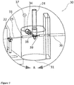
- FIG 2 shows a desktop DDLS instrument 20 to characterize biological cells according to the present invention.
- the instrument components include a laser 21 to produce a collimated incident beam of light 23, which may be focused through lenses 22.
- the incident laser beam may alternatively be conveyed using an optic fiber.
- Laser beam 23 enters sample vessel assembly 30 which is further detailed in Figure 3 .
- a laser beam 23 enters an opening 33 in support 31 where the beam impinges on sample vessel 24 containing biological material of interest. Part of the beam 23 scatters off electrode 38 to generate a heterodyne mode that allows easy detection and correlation.
- An electric field gradient is created between electrodes 38 and 39 by oscillating power supply 37 which is connected to the electrodes through connector 34. Scattered light 27 is collected in optical fiber 36.
- optical fiber 36 connects to a photodetector 25, which may be a device that uses the photoelectric effect to convert radiant energy into an electrical signal such as a photodiode or a phototube.
- Photodetector 25 is preferably a photon counting photomultiplier tube (PMT) or preferably an avalanche photodiode (APD). Any light detecting method or device is within the scope of the present invention.
- the electrical signal from the photodetector enters digital correlator 26 which constructs the autocorrelation function (Equations 3 and 6).
- the output of the digital correlator is digitized usually by an analog to digital converter (A/D converter) and analyzed by logic, typically in a processor, to correlate the autocorrelation functions to glucose levels from stored calibration curve or to take a Fourier Transform (FT) and correlate spectral peaks.
- a microprocessor, microcontroller, digital signal processor or other processor with appropriate programming is generally used for such tasks.
- the analysis uses the Fourier Transform FT as discussed above.
- Fourier Transforms can conveniently be realized by algorithms known as Fast-Fourier Transforms (FFT).
- FFT Fast-Fourier Transforms
- Various windowing and zero-padding techniques known in the art may be used to aid in taking the FT.
- the system shown in Figure 2 can be used to characterize the parameters of oscillator frequency, field strength (and oscillator voltage), gradient strength, beam wavelength, laser power and other necessary parameters such as refractive index and viscosity of the subject material.
- Characterization of the above parameters enables the utilization of these parameters in the non-invasive operation of the present invention.
- the sample is placed in the sample vessel 24 where the electrodes generate an electric field gradient after energizing the oscillating power supply 37.
- the sample vessel walls may be of glass, quartz, or clear plastic.
- the sample vessel may be immersed in a bath of refractive index-matching fluid, e.g., silicon oil.
- the temperature may be controlled by a thermoelectric (Peltier) device, such as those that can be obtained from TE Technologies of Traverse City, MI, USA.
- oscillating power supply 37 may consist of an electrical function generator producing an oscillating electrical signal (typically sinusoidal) which can be amplified by a broad-band amplifier and fed to two electrodes 38 and 39.
- the field gradient is achieved by arrangement of the two mentioned electrodes in a fashion similar to that depicted in Figures 1A, 1B and Figure 6 .
- the electrodes may be configured to produce a uniform gradient to minimize field gradient inhomogeneity in the scattering volume.
- the field gradient can range from 10 4 V 2 /m 3 to 10 20 V 2 /m 3 and preferably from 10 12 to 5x10 15 V 2 /m 3 .
- Preferred oscillating electric field gradient strengths are chosen to cause polarization of the biological cells in specified areas of the body.
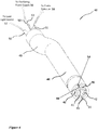
- Figures 4-7 show an embodiment for a device 40 for non-invasive measurement of glucose contained in biological fluids, e.g., blood in a non-invasive manner according to the present invention.
- Figure 5 shows an exploded view of the device in Figure 4 with the inner components outlined with dashed lines.
- Device 40 includes two electrodes 41 and 42 arranged to generate an electric field gradient.
- the oscillating electric power supply 56 (not shown in) is capable of generating an oscillating electrical field by supplying sufficient voltage to achieve sufficient field gradients.
- Electrode connectors 43 and 44 are seated in grooves 54 and 55 and connect to the oscillating electrical power supply 56 through connectors 52 and 53.
- the oscillating electrical power supply 56 may include an electrical function generator which generates a sinusoidal electrical wave, a square or triangular wave, or any other waveform, which is fed to an electrical signal amplifier to adjust the electrical waves' amplitude.
- the voltage between the tip and ground should not exceed recommended safe medical levels. If the tip is properly insulated, at least 40 V p-p may be used. The maximum allowed voltage will vary from country to country based on national safety standards.
- the connection is achieved by assembling the electrodes into guiding grooves 54 and 55. When the oscillating electric power supply 56 is energized, the oscillating electrical voltage supplied to the two electrodes 41 and 42 causes the creation of an oscillating electric field gradient.
- Electrodes are further illustrated in Figure 6 , where electrodes 41 and 42, due to their geometrical ring or partial ring shape, create a field gradient when connected to the electric power supply.
- Other electrode configurations such as the configuration in Figures 1A-1B , may also be used.
- the electrodes and fiber optics configuration at the end that interacts with specific areas of body may be optionally thermostated to allow performing measurements at specified temperatures.
- electrodes 41 and 42 can be placed in a specified position, e.g., distance and orientation, with respect to a specified area of the body, such as finger nail, forearm, cheek, palm, stomach skin, earlobe, eye's humor etc. It is preferred that the two electrodes be safely insulated, and that the distance from the specific body part be as small as possible, preferably between 0 and 5 mm.
- a clamp may be used to repeatably position the electrodes in the specified position with respect to the specified area of the body.
- the light source 57 is preferably a laser, and preferably a solid state, single mode laser (such as may be provided by e.g., Quartron, Inc., Chino, CA, USA). While a laser is the preferred light source, any light source is within the scope of the present invention.
- Light source 57 may produce collimated light with a wavelength in the near UV, visible, or near infrared regions. Different wavelengths can be used with different tissue or sample types.
- the incoming light can be coupled through an optical fiber cable 50, where the light beam is transmitted to impinge on the sample of interest.
- Incident light is scattered by the sample, and the scattered light can be transmitted through optical fiber cable 51 to a photodetector 58, such as a PMT or an APD (such as that provided by e.g., Hamamatsu Photonics K.K., Hamamatsu City, Japan).
- a photodetector 58 such as a PMT or an APD (such as that provided by e.g., Hamamatsu Photonics K.K., Hamamatsu City, Japan).
- flat surface Gradient-index (GRIN) lenses 45 and 46 may also be used for efficient coupling of the incident light and the scattered light to the optical fiber cables 50 and 51, respectively.
- Optical fiber cables and electrode wires are preferably enclosed in a flexible conduit for ease of orienting and positioning of the device with human body parts.
- a flexible part of conduit 49 encases the wires connecting electrodes 41 and 42 to the oscillating electrical power supply 56, and the optical fiber cables 50 and 51 to light source 57 and photodetector 58 respectively.
- a rigid portion 48 encases the electrode and fiber optics in a fixed configuration to ensure repeatability and ease of positioning with respect to the specified body part.
- Lens or optical fiber end 45 focuses the beam on the target.
- Lens or optical fiber end 46 collects the scattered light.
- Scattered light from the interaction of the incident light beam with specific areas of the body is affected by the motion of biological cells, e.g., in blood, ISF, or serum. Since the cells are also affected by the electric field gradient, the scattered light contains information pertaining to the scattering cells. As discussed previously, the motion of cells whose conditions are affected by glucose concentration, e.g., RBC can indicate their glycation state. Therefore, analysis of the scattered light produces correlation to the status of cell glycation. The scattered light, collected at a specified angle ⁇ , is converted by a photodetector 58, to electric signals.
- the electric signals may be digitized by an analog-to-digital converter as known in the art, and may be integrated with the photodetector and a correlator to a construct time autocorrelation functions.
- the photodetector 58 is preferably a photon-counting PMT or an APD.
- the autocorrelator output may be used by a computer or other processor with logic to further analyze the autocorrelation functions by the construction of a FT and storing the resulting velocity spectra for comparison with calibration data or as databases.
- FIG. 7 shows an enlarged schematic of the bottom end of an embodiment of the present invention which details the application of the device to non-invasive measurement by positioning the device on or above the thumb nail area 59.
- Electrodes 41 and 42 are positioned at close distance from a translucent area of the body, e.g., thumb nail 59. With the oscillating power supply energized, an oscillating electric field gradient is created in the tissue under the thumbnail.
- Incident light beam 60 impinges on and is scattered by cells that respond to the applied field gradient.
- the scattered beam 61 enters fiber optic through 46 and travels to the photodetector.
- the position of the device with respect to the body part e.g., the thumb nail, may be aided by marking and clamping accessories.
- a computer or other processor with appropriate logic and software algorithms may be utilized to perform the data analysis previously discussed.
- the present invention provides a method for non-invasive indication of glucose levels in the body by measuring the effect of glucose on the response of biological cells to the application of an oscillating electric field gradient on a specified area of the human body.
- Preferred areas of the body are characterized by being slightly opaque or translucent to allow for moderate penetration of the light beam into the tissues and the escape of the scattered light from areas of the body with biological cells-containing fluids such as blood, serum, and ISF.
- suitable areas of body include, but are not limited to, the finger nails, forearm, cheek, palm, stomach skin, earlobe, or the eye. It is preferable that the same areas be repeatedly used.
- the spectrum due to the Brownian motion may be estimated by curve-fitting C' norm ( ⁇ ) to an exponential function which is the functional form of C( ⁇ ).
- the curve fitting may be accomplished by, for example, non-least square minimization procedure using special software or commercial software such as Microsoft's EXCEL Solver add-in (Microsoft, Redmond, CA, USA).
- the oscillations due to DDLS (the term e - iq .v ⁇ in Equation 7) can be obtained by dividing C ' norm ( ⁇ ) by the exponential estimation of C( ⁇ ). This can be important in removing the static scattering components in addition to reducing the occurrence of low frequency peaks in the FT.
- the FT analysis can then be applied to the resulting function, and preferably, the FT is performed on the functional form: [(C norm '( ⁇ ) / C norm ( ⁇ ))-1] to render the oscillations symmetrical around zero and to minimize high frequency ripples (or side lobes) due to the presence of sharp truncation functions.
- "zero filling or padding", or window functions may be used to improve the resolution in the FT and remove artifacts such as those caused by Gibbs phenomena known in the art.
- the velocities in the FT spectrum may be normalized (using the applied field strength and gradient) to correlate measurements under different conditions. The FT thus, under specified conditions, presents a "finger print" of the sample.
- Peaks in the FT may be assigned to particular components, e.g., RBC.
- the peaks can then be used to study changes to the specified components due to glucose variations which indicate glycation extent.
- the data analysis scheme just described is preferred, although other analyses and algorithms familiar to those skilled in the art may be applied.
- An important component of the present invention is to the construct a "calibration" to correlate the measurements made with the instrument of the invention with established glucose measurements using validated glucose meters.
- the calibration measurements are used to construct a look-up table, or "calibration look-up table", to retrieve glucose values corresponding to peaks in the FT spectra.
- a mathematical equation that can be called a “calibration equation” can be constructed from fitting observed data: peaks in the FT spectra, treated as indicated above, vs. glucose concentration determined by validated glucose level meters. This correlation can be used to non-invasively calculate the glucose concentration from measurements using the present invention.
- a method of correlating non-invasive DDLS measurements to validated glucose meter measurements is presented, thus establishing a calibration data set or "calibration procedure".
- a possible calibration uses the following steps:
- step ii-a is the curve fitting of an exponential function, which is the functional form of the autocorrelation function to obtain C( ⁇ ) , to the data collected in step ii-c for use with the analysis discussed above.
- Other functional forms e.g., multiple exponentials, polynomials or other smooth functions may also be used as fitting function.
- step iv- is the construction of calibration equation from the calibration table data.
- An embodiment for use of the current invention provides a method for non-invasive indication of glucose levels in a subject, accomplished by measuring the effect of glucose on the response of specific biological cells, e.g., RBC, to the application of an oscillating electric field gradient on a specified area of the body using the device of Figures 4-7 , and including the following steps:
- step i- is the curve fitting of an exponential or other functions to the data collected in step ii- to as discussed above.
- Another embodiment of the present invention is its application to non-invasive detection of glucose changes by applying DDLS measurements to biological fluids other than blood, e.g., saliva or urine, using the embodiment described in Figure 2 .
- the methods above may be used to construct a calibration table or calibration mathematical equation for individual patients.
- the measurements may be performed under specified conditions of time of day, metabolic state, and ambient temperature and humidity.
- a globalized correlation may be established where a look-up table or a mathematical function may serve as reference for glucose level determination for a group of patients. Subpopulations of patients may be identified that share similar calibration characteristics.
- the present inventions may be applied to other areas such as the identification of biological cells, biological macromolecules and polymeric substances.
- the present invention affords a method by which biological cells are identified by their FT spectrum under normalized conditions of electric field strength, electric field gradient, applied light source, frequency, and the like.
- the response of the biological cells to the field gradient and the subsequent autocorrelation function measurement, data analysis procedures and FT spectral analysis can follow steps similar to those described in the above embodiments and using devices similar to those of Figures 2 and 7 .
- Calibration methods include assignment of FT spectral features to normal biological cells, which may be used to identify such normal cells.
- Some biological cells are known to be "not-normal" by current medical conventions, and may also be characterized by applying procedures as outlined above.
- Conditions that would render a cell not-normal may include cancer, metabolic stress, aging, genetic diseases, and infection by bacteria, viruses or other infectants.
- the FT spectral response described is correlated with established or validated identification of biological cells with the methods presented in the present invention.
- the construction of a repository of correlated data allows the use of the present invention to detect cell conditions, and thus offers diagnosis of biological cell maladies including cancer, aging, genetic diseases, infectious diseases and other stresses.
- Similar devices and methods may be applied by the present invention to the detection of infectious organisms such as bacteria and viruses.
- the present invention may also be applied to the identification of macromolecules.
- macromolecule it is meant a molecule of molecular weight above 50,000 Daltons, and preferably in the range of 100 kilo Daltons to 100 Giga Daltons.
- PCR polymerase chain reactions
Landscapes
- Health & Medical Sciences (AREA)
- Life Sciences & Earth Sciences (AREA)
- Physics & Mathematics (AREA)
- Engineering & Computer Science (AREA)
- General Health & Medical Sciences (AREA)
- Molecular Biology (AREA)
- Biomedical Technology (AREA)
- Heart & Thoracic Surgery (AREA)
- Medical Informatics (AREA)
- Pathology (AREA)
- Surgery (AREA)
- Animal Behavior & Ethology (AREA)
- Biophysics (AREA)
- Public Health (AREA)
- Veterinary Medicine (AREA)
- Optics & Photonics (AREA)
- Nuclear Medicine, Radiotherapy & Molecular Imaging (AREA)
- Radiology & Medical Imaging (AREA)
- Mathematical Physics (AREA)
- Spectroscopy & Molecular Physics (AREA)
- Emergency Medicine (AREA)
- Artificial Intelligence (AREA)
- Computer Vision & Pattern Recognition (AREA)
- Physiology (AREA)
- Psychiatry (AREA)
- Signal Processing (AREA)
- Electrochemistry (AREA)
- Chemical Kinetics & Catalysis (AREA)
- Chemical & Material Sciences (AREA)
- Microelectronics & Electronic Packaging (AREA)
- Measurement Of The Respiration, Hearing Ability, Form, And Blood Characteristics Of Living Organisms (AREA)
Claims (15)
- Eine tragbare, nicht-invasive Glukosemessvorrichtung, umfassend:eine Sonde (40), die konfiguriert ist, um ein oszillierendes, ungleichmäßiges elektrisches Feld auf einem vorbestimmten Teil eines menschlichen Körpers zu erzeugen;wobei die Sonde auch konfiguriert ist, um einen gebündelten Lichtstrahl auf den vorbestimmten Teil zu erzeugen und gestreutes Licht in einen Detektor (25, 58) zu leiten;einen Prozessor in Kommunikation mit der Sonde, wobei der Prozessor ein Programm ausführt, das eine zeitliche Autokorrelation in Bezug auf das gestreute Licht erzeugt;das Programm die Autokorrelation oder eine Funktion der Autokorrelation mit einer Kalibrierung vergleicht, um einen Glukosewert zu Bestimmen;dadurch gekennzeichnet, dassdas ungleichmäßige elektrische Feld durch eine erste und eine zweite Elektrode gebildet wird, wobei die erste Elektrode (11, 42) ein Ring oder Teilring ist; undwobei die zweite Elektrode (12, 41) an einem Punkt in der Nähe eines Mittelpunktes des Rings angeordnet ist.
- Die tragbare, nicht-invasive Glukosemessvorrichtung nach Anspruch 1, wobei der Lichtstrahl von einem Laser (21, 57) geliefert wird.
- Die tragbare, nicht-invasive Glukosemessvorrichtung nach Anspruch 1, wobei der Detektor (25, 58) ein Photomultiplier oder eine Fotodiode ist.
- Die tragbare, nicht-invasive Glukosemessvorrichtung nach Anspruch 1, wobei das oszillierende, ungleichmäßige elektrische Feld durch eine oszillierende Stromversorgung (37, 56) versorgt wird.
- Die tragbare, nicht-invasive Glukosemessvorrichtung nach Anspruch 1, wobei der Lichtstrahl von einem Laser (21, 57) geliefert wird;
der Detektor (25, 58) ein Photomultiplier oder eine Fotodiode ist;
und das oszillierende, ungleichmäßige elektrische Feld von einer oszillierenden Stromversorgung (37, 56) versorgt wird. - Die tragbare, nicht-invasive Glukosemessvorrichtung nach Anspruch 5, wobei der Prozessor, der Laser, der Detektor und die oszillierende Stromversorgung von der Sonde getrennt sind, und wobei Licht über Lichtwellenleiter vom Laser zu der Sonde und von der Sonde zu dem Detektor geführt wird, und eine Spannung von der oszillierenden Stromversorgung an die Sonde über einen elektrischen Leiter angelegt wird, um das ungleichmäßige Feld zu bilden.
- Die tragbare, nicht-invasive Glukosemessvorrichtung nach Anspruch 1, wobei das Programm, das die Autokorrelationsfunktion erzeugt, eine Korrelationsvorrichtung verwendet.
- Die tragbare, nicht-invasive Glukosemessvorrichtung nach Anspruch 1, wobei das Programm bei der Autokorrelation eine Fourier-Transformation durchführt.
- Die tragbare, nicht-invasive Glukosemessvorrichtung nach Anspruch 1, wobei das ungleichmäßige elektrische Feld einen Gradienten zwischen etwa 10 Volt/cm2 und etwa 109 Volt/cm2 aufweist.
- Die tragbare, nicht-invasive Glukosemessvorrichtung nach Anspruch 4, wobei die oszillierende Stromversorgung eine oszillierende Spannung zwischen etwa 1 Volt und 1000 Volt liefert.
- Die tragbare, nicht-invasive Glukosemessvorrichtung nach Anspruch 1, wobei die Kalibrierungsfunktion durch Bilden einer Vielzahl von Autokorrelationen oder Funktionen von Autokorrelationen mit der Vorrichtung bei unterschiedlichen Glukosewerten und Vergleichen jeweils mit einem kalibrierten Glukosewert, der nahe der gleichen Zeit am gleichen Objekt mit einer validierten Glukosemessvorrichtung gemessen wurde, vorgenommen ist.
- Die tragbare, nicht-invasive Glukosemessvorrichtung nach Anspruch 1, wobei das ungleichmäßige elektrische Feld durch eine erste und eine zweite Elektrode gebildet wird, wobei die erste Elektrode ein Ring oder Teilring ist;
wobei die zweite Elektrode an einem Punkt in der Nähe eines Mittelpunktes des Rings angeordnet ist. - Die tragbares, nicht-invasives Glukosemessvorrichtung nach Anspruch 1, ferner umfassend eine Elektrode, die das ungleichmäßige elektrische Feld erzeugt, und wobei ein Abschnitt des gebündelten Lichtstrahls von der Elektrode in den Detektor reflektiert wird, um eine Überlagerung zu erzeugen.
- Ein Verfahren zur In-vivo-Messung eines Glukosespiegels in einem Biofluid, dadurch gekennzeichnet, dass es eine tragbare Sonde verwendet, umfassend:Aussetzen des Biofluids gegenüber einem ungleichmäßigen, oszillierenden elektrischen Feld, wobei das Feld von Elektroden in der Sonde stammt;Streuen eines Lichtstrahls an dem Biofluid in einen Detektor (25, 58);Verarbeiten einer Ausgabe des Detektors, um eine Autokorrelation zu bilden;Berechnen einer mathematischen Transformation der Autokorrelation, um ein Frequenzspektrum zu erzeugen;Vergleichen mindestens eines Peaks im Frequenzspektrum mit einer Kalibrierung, um einen Glukosewert in dem Biofluid zu bestimmen,und dadurch gekennzeichnet, dassdas ungleichmäßige elektrische Feld durch eine erste und eine zweite Elektrode gebildet wird, wobei die erste Elektrode (11, 42) ein Ring oder Teilring ist; undwobei die zweite Elektrode (12, 41) an einem Punkt in der Nähe eines Mittelpunktes des Rings angeordnet ist.
- Das Verfahren nach Anspruch 14, ferner umfassend:
Herstellen der Kalibrierung durch Messen des Glukosewertes bei Testobjekten unter Verwendung der Sonde und Vergleichen des Glukosespiegels mit den mit einer validierten Glukosemessvorrichtung gemessenen Werten.
Applications Claiming Priority (2)
| Application Number | Priority Date | Filing Date | Title |
|---|---|---|---|
| US13/683,924 US8843186B2 (en) | 2012-11-21 | 2012-11-21 | Non-invasive reagentless glucose determination |
| PCT/US2013/069354 WO2014081586A1 (en) | 2012-11-21 | 2013-11-09 | Non-invasive reagentless glucose determination |
Publications (3)
| Publication Number | Publication Date |
|---|---|
| EP2922469A1 EP2922469A1 (de) | 2015-09-30 |
| EP2922469A4 EP2922469A4 (de) | 2016-07-20 |
| EP2922469B1 true EP2922469B1 (de) | 2020-01-08 |
Family
ID=50728587
Family Applications (1)
| Application Number | Title | Priority Date | Filing Date |
|---|---|---|---|
| EP13857061.9A Active EP2922469B1 (de) | 2012-11-21 | 2013-11-09 | Nichtinvasive reagenzienlose glucosebestimmung |
Country Status (3)
| Country | Link |
|---|---|
| US (1) | US8843186B2 (de) |
| EP (1) | EP2922469B1 (de) |
| WO (1) | WO2014081586A1 (de) |
Families Citing this family (11)
| Publication number | Priority date | Publication date | Assignee | Title |
|---|---|---|---|---|
| US9031640B2 (en) * | 2007-12-21 | 2015-05-12 | Institute Of National Colleges Of Technology, Japan | Laser doppler blood flow measuring method and device |
| WO2016049103A1 (en) * | 2014-09-23 | 2016-03-31 | Halaka Folim G | Cancer cell detection using dielectrophoretic dynamic light scattering (ddls) spectroscopy |
| WO2016054079A1 (en) | 2014-09-29 | 2016-04-07 | Zyomed Corp. | Systems and methods for blood glucose and other analyte detection and measurement using collision computing |
| CN105486731B (zh) * | 2015-08-12 | 2018-08-21 | 成都市亿泰科技有限公司 | 基于太赫兹增强的无创血糖检测探头 |
| CN108601563B (zh) | 2015-12-24 | 2021-11-02 | 森索富洛公司 | 非侵入性感测系统 |
| US9554738B1 (en) | 2016-03-30 | 2017-01-31 | Zyomed Corp. | Spectroscopic tomography systems and methods for noninvasive detection and measurement of analytes using collision computing |
| KR102655736B1 (ko) * | 2016-07-19 | 2024-04-05 | 삼성전자주식회사 | 이종 스펙트럼 기반 혈당 추정 장치 및 방법 |
| WO2019110084A1 (de) * | 2017-12-04 | 2019-06-13 | Diamontech Gmbh | Vorrichtung und verfahren zum analysieren eines stoffs |
| US11796466B2 (en) * | 2020-07-17 | 2023-10-24 | The Board of Regents for the Oklahoma Agricultural and Mechanical Colleges | System and method of non-contact glucose sensing |
| DE102020127957A1 (de) | 2020-10-23 | 2022-04-28 | eTouch Medical Inc. | Cloud-System zur nicht-invasiven Blutzuckermessung |
| MA63555B1 (fr) * | 2023-12-28 | 2025-10-31 | Fondation de Recherche de Développement et d'Innovation en Sciences et Ingénierie | Conception et Développement d'un Smart Glucomètre non invasif à longue durée de vie |
Family Cites Families (36)
| Publication number | Priority date | Publication date | Assignee | Title |
|---|---|---|---|---|
| US3766048A (en) | 1972-11-24 | 1973-10-16 | Univ Illinois | Analysis of polymer mixtures in solution utilizing electrophoretic light scattering apparatus |
| US4882492A (en) | 1988-01-19 | 1989-11-21 | Biotronics Associates, Inc. | Non-invasive near infrared measurement of blood analyte concentrations |
| US5009230A (en) | 1988-05-31 | 1991-04-23 | Eol, Inc. | Personal glucose monitor |
| US4901728A (en) | 1988-05-31 | 1990-02-20 | Eol, Inc. | Personal glucose monitor |
| US5070874A (en) | 1990-01-30 | 1991-12-10 | Biocontrol Technology, Inc. | Non-invasive determination of glucose concentration in body of patients |
| US5222496A (en) | 1990-02-02 | 1993-06-29 | Angiomedics Ii, Inc. | Infrared glucose sensor |
| US5119819A (en) | 1990-05-02 | 1992-06-09 | Miles Inc. | Method and apparatus for non-invasive monitoring of blood glucose |
| US5298967A (en) | 1992-06-02 | 1994-03-29 | Pacific Scientific Company | Measurement of concentrations of dissolved solvent |
| US5448992A (en) | 1992-12-10 | 1995-09-12 | Sunshine Medical Instruments, Inc. | Method and apparatus for non-invasive phase sensitive measurement of blood glucose concentration |
| JP3433498B2 (ja) * | 1993-06-02 | 2003-08-04 | 浜松ホトニクス株式会社 | 散乱吸収体の内部情報計測方法及び装置 |
| US5459317A (en) | 1994-02-14 | 1995-10-17 | Ohio University | Method and apparatus for non-invasive detection of physiological chemicals, particularly glucose |
| US5553613A (en) | 1994-08-17 | 1996-09-10 | Pfizer Inc. | Non invasive blood analyte sensor |
| US5581349A (en) | 1995-03-27 | 1996-12-03 | Halaka; Folim G. | Method for biological cell and particulate analysis |
| US5703364A (en) | 1996-02-15 | 1997-12-30 | Futrex, Inc. | Method and apparatus for near-infrared quantitative analysis |
| US20020095075A1 (en) * | 1996-09-10 | 2002-07-18 | Frank Madarasz | Photonic molecular probe applications |
| JP4212007B2 (ja) | 1996-11-26 | 2009-01-21 | パナソニック電工株式会社 | 血液成分濃度の分析装置 |
| US5823966A (en) | 1997-05-20 | 1998-10-20 | Buchert; Janusz Michal | Non-invasive continuous blood glucose monitoring |
| US6043492A (en) | 1997-10-27 | 2000-03-28 | Industrial Technology Research Institute | Non-invasive blood glucose meter |
| JP4369616B2 (ja) | 1997-11-12 | 2009-11-25 | ライタッチ メディカル インコーポレイテッド | 検体を非侵襲的に測定する方法及び装置 |
| US6505059B1 (en) | 1998-04-06 | 2003-01-07 | The General Hospital Corporation | Non-invasive tissue glucose level monitoring |
| CA2337097C (en) | 1998-07-13 | 2008-12-23 | James L. Lambert | Non-invasive glucose monitor |
| US6424851B1 (en) | 1998-10-13 | 2002-07-23 | Medoptix, Inc. | Infrared ATR glucose measurement system (II) |
| US6841389B2 (en) | 2001-02-05 | 2005-01-11 | Glucosens, Inc. | Method of determining concentration of glucose in blood |
| US6574490B2 (en) | 2001-04-11 | 2003-06-03 | Rio Grande Medical Technologies, Inc. | System for non-invasive measurement of glucose in humans |
| US6748250B1 (en) | 2001-04-27 | 2004-06-08 | Medoptix, Inc. | Method and system of monitoring a patient |
| JP3931638B2 (ja) | 2001-11-15 | 2007-06-20 | 松下電工株式会社 | 生体成分の定量装置 |
| US7050847B2 (en) | 2002-03-26 | 2006-05-23 | Stig Ollmar | Non-invasive in vivo determination of body fluid parameter |
| WO2005004712A1 (en) * | 2003-07-09 | 2005-01-20 | Glucon Inc. | Wearable glucometer |
| US20050054907A1 (en) | 2003-09-08 | 2005-03-10 | Joseph Page | Highly portable and wearable blood analyte measurement system |
| JP2009519765A (ja) | 2005-12-16 | 2009-05-21 | バイエル・ヘルスケア・エルエルシー | 組織中のグルコース−媒介性変化のin−vivo非−侵襲性生体電気インピーダンス解析 |
| JP2009521972A (ja) | 2005-12-28 | 2009-06-11 | コーニンクレッカ フィリップス エレクトロニクス エヌ ヴィ | 被検体のスキンハイドレーションを測定するための非侵襲性システム及び方法 |
| US8321025B2 (en) * | 2006-07-31 | 2012-11-27 | Cranial Medical Systems, Inc. | Lead and methods for brain monitoring and modulation |
| JP2010508056A (ja) * | 2006-10-30 | 2010-03-18 | エルフィ−テック リミテッド | 生物学的パラメータの体内での測定のためのシステム及び方法 |
| JP2010515046A (ja) * | 2006-12-28 | 2010-05-06 | コーニンクレッカ フィリップス エレクトロニクス エヌ ヴィ | 分光測定 |
| US20100112614A1 (en) | 2008-11-06 | 2010-05-06 | Physical Logic Ag | Coupled Antenna Impedance Spectroscopy |
| US20120116236A1 (en) | 2010-11-04 | 2012-05-10 | Joshua Noel Hogan | Hydration and blood flow adjusted glucose measurement |
-
2012
- 2012-11-21 US US13/683,924 patent/US8843186B2/en active Active
-
2013
- 2013-11-09 WO PCT/US2013/069354 patent/WO2014081586A1/en not_active Ceased
- 2013-11-09 EP EP13857061.9A patent/EP2922469B1/de active Active
Non-Patent Citations (1)
| Title |
|---|
| None * |
Also Published As
| Publication number | Publication date |
|---|---|
| US20140142400A1 (en) | 2014-05-22 |
| US8843186B2 (en) | 2014-09-23 |
| EP2922469A1 (de) | 2015-09-30 |
| WO2014081586A1 (en) | 2014-05-30 |
| EP2922469A4 (de) | 2016-07-20 |
Similar Documents
| Publication | Publication Date | Title |
|---|---|---|
| US8843186B2 (en) | Non-invasive reagentless glucose determination | |
| CN108369183B (zh) | 用于分析材料的装置和方法 | |
| US6353226B1 (en) | Non-invasive sensor capable of determining optical parameters in a sample having multiple layers | |
| Yuen et al. | Transcutaneous glucose sensing by surface-enhanced spatially offset Raman spectroscopy in a rat model | |
| JP4936203B2 (ja) | グルコース濃度の定量装置 | |
| JP5119252B2 (ja) | 脈を打つ血液におけるグルコース濃度を測定する方法 | |
| Mosca et al. | Spatially offset and transmission Raman spectroscopy for determination of depth of inclusion in turbid matrix | |
| US20040260162A1 (en) | Analysis system for reagent-free determination of the concentration of an analyte in living tissue | |
| JP2001524342A (ja) | 多重センサー及び使用方法 | |
| WO1999059464A1 (en) | Non-invasive optical sensor with control of tissue temperature | |
| Srivastava et al. | Blood glucose monitoring using non invasive optical method: Design limitations and challenges | |
| US9693694B2 (en) | Cancer cell detection using dielectrophoretic dynamic light scattering (DDLS) spectroscopy | |
| JP2005508007A (ja) | 無試薬全血ブドウ糖計 | |
| Yadav et al. | Comparative study of different measurement sites using NIR based non-invasive glucose measurement system | |
| Chen et al. | Non-invasive blood glucose measurement based on mid-infrared spectroscopy | |
| Losoya-Leal et al. | State of the art and new perspectives in non-invasive glucose sensors | |
| RU2438130C2 (ru) | Способ определения содержания глюкозы в клетке крови | |
| Moore et al. | Principles of vibrational spectroscopic methods and their application to bioanalysis | |
| WO2007060583A2 (en) | Method and apparatus for determining concentrations of analytes in a turbid medium | |
| US20250130173A1 (en) | Detection using sers probes | |
| US20040152089A1 (en) | Method for the determination of a light transport parameter in a biological matrix | |
| Morsin et al. | Development of plasmonic sensor for detection of toxic materials | |
| Talukdar | Non-Invasive Measurement of Glucose Content in Human Body: A Comparative Study | |
| Bazaev et al. | Noninvasive methods for blood glucose measurement | |
| GB2531956A (en) | Device and method for characterisation of biological samples |
Legal Events
| Date | Code | Title | Description |
|---|---|---|---|
| PUAI | Public reference made under article 153(3) epc to a published international application that has entered the european phase |
Free format text: ORIGINAL CODE: 0009012 |
|
| 17P | Request for examination filed |
Effective date: 20150617 |
|
| AK | Designated contracting states |
Kind code of ref document: A1 Designated state(s): AL AT BE BG CH CY CZ DE DK EE ES FI FR GB GR HR HU IE IS IT LI LT LU LV MC MK MT NL NO PL PT RO RS SE SI SK SM TR |
|
| AX | Request for extension of the european patent |
Extension state: BA ME |
|
| DAX | Request for extension of the european patent (deleted) | ||
| RA4 | Supplementary search report drawn up and despatched (corrected) |
Effective date: 20160617 |
|
| RIC1 | Information provided on ipc code assigned before grant |
Ipc: A61B 5/1477 20060101AFI20160613BHEP |
|
| GRAP | Despatch of communication of intention to grant a patent |
Free format text: ORIGINAL CODE: EPIDOSNIGR1 |
|
| STAA | Information on the status of an ep patent application or granted ep patent |
Free format text: STATUS: GRANT OF PATENT IS INTENDED |
|
| RAP1 | Party data changed (applicant data changed or rights of an application transferred) |
Owner name: HALAKA, FOLIM |
|
| RIN1 | Information on inventor provided before grant (corrected) |
Inventor name: HALAKA, FOLIM |
|
| INTG | Intention to grant announced |
Effective date: 20190805 |
|
| GRAS | Grant fee paid |
Free format text: ORIGINAL CODE: EPIDOSNIGR3 |
|
| GRAA | (expected) grant |
Free format text: ORIGINAL CODE: 0009210 |
|
| STAA | Information on the status of an ep patent application or granted ep patent |
Free format text: STATUS: THE PATENT HAS BEEN GRANTED |
|
| AK | Designated contracting states |
Kind code of ref document: B1 Designated state(s): AL AT BE BG CH CY CZ DE DK EE ES FI FR GB GR HR HU IE IS IT LI LT LU LV MC MK MT NL NO PL PT RO RS SE SI SK SM TR |
|
| REG | Reference to a national code |
Ref country code: GB Ref legal event code: FG4D |
|
| REG | Reference to a national code |
Ref country code: CH Ref legal event code: EP |
|
| REG | Reference to a national code |
Ref country code: DE Ref legal event code: R096 Ref document number: 602013064970 Country of ref document: DE |
|
| REG | Reference to a national code |
Ref country code: IE Ref legal event code: FG4D |
|
| REG | Reference to a national code |
Ref country code: AT Ref legal event code: REF Ref document number: 1221657 Country of ref document: AT Kind code of ref document: T Effective date: 20200215 |
|
| REG | Reference to a national code |
Ref country code: NL Ref legal event code: MP Effective date: 20200108 |
|
| REG | Reference to a national code |
Ref country code: LT Ref legal event code: MG4D |
|
| PG25 | Lapsed in a contracting state [announced via postgrant information from national office to epo] |
Ref country code: NO Free format text: LAPSE BECAUSE OF FAILURE TO SUBMIT A TRANSLATION OF THE DESCRIPTION OR TO PAY THE FEE WITHIN THE PRESCRIBED TIME-LIMIT Effective date: 20200408 Ref country code: FI Free format text: LAPSE BECAUSE OF FAILURE TO SUBMIT A TRANSLATION OF THE DESCRIPTION OR TO PAY THE FEE WITHIN THE PRESCRIBED TIME-LIMIT Effective date: 20200108 Ref country code: PT Free format text: LAPSE BECAUSE OF FAILURE TO SUBMIT A TRANSLATION OF THE DESCRIPTION OR TO PAY THE FEE WITHIN THE PRESCRIBED TIME-LIMIT Effective date: 20200531 Ref country code: NL Free format text: LAPSE BECAUSE OF FAILURE TO SUBMIT A TRANSLATION OF THE DESCRIPTION OR TO PAY THE FEE WITHIN THE PRESCRIBED TIME-LIMIT Effective date: 20200108 Ref country code: LT Free format text: LAPSE BECAUSE OF FAILURE TO SUBMIT A TRANSLATION OF THE DESCRIPTION OR TO PAY THE FEE WITHIN THE PRESCRIBED TIME-LIMIT Effective date: 20200108 Ref country code: RS Free format text: LAPSE BECAUSE OF FAILURE TO SUBMIT A TRANSLATION OF THE DESCRIPTION OR TO PAY THE FEE WITHIN THE PRESCRIBED TIME-LIMIT Effective date: 20200108 |
|
| PG25 | Lapsed in a contracting state [announced via postgrant information from national office to epo] |
Ref country code: SE Free format text: LAPSE BECAUSE OF FAILURE TO SUBMIT A TRANSLATION OF THE DESCRIPTION OR TO PAY THE FEE WITHIN THE PRESCRIBED TIME-LIMIT Effective date: 20200108 Ref country code: LV Free format text: LAPSE BECAUSE OF FAILURE TO SUBMIT A TRANSLATION OF THE DESCRIPTION OR TO PAY THE FEE WITHIN THE PRESCRIBED TIME-LIMIT Effective date: 20200108 Ref country code: GR Free format text: LAPSE BECAUSE OF FAILURE TO SUBMIT A TRANSLATION OF THE DESCRIPTION OR TO PAY THE FEE WITHIN THE PRESCRIBED TIME-LIMIT Effective date: 20200409 Ref country code: BG Free format text: LAPSE BECAUSE OF FAILURE TO SUBMIT A TRANSLATION OF THE DESCRIPTION OR TO PAY THE FEE WITHIN THE PRESCRIBED TIME-LIMIT Effective date: 20200408 Ref country code: IS Free format text: LAPSE BECAUSE OF FAILURE TO SUBMIT A TRANSLATION OF THE DESCRIPTION OR TO PAY THE FEE WITHIN THE PRESCRIBED TIME-LIMIT Effective date: 20200508 Ref country code: HR Free format text: LAPSE BECAUSE OF FAILURE TO SUBMIT A TRANSLATION OF THE DESCRIPTION OR TO PAY THE FEE WITHIN THE PRESCRIBED TIME-LIMIT Effective date: 20200108 |
|
| REG | Reference to a national code |
Ref country code: DE Ref legal event code: R097 Ref document number: 602013064970 Country of ref document: DE |
|
| PG25 | Lapsed in a contracting state [announced via postgrant information from national office to epo] |
Ref country code: ES Free format text: LAPSE BECAUSE OF FAILURE TO SUBMIT A TRANSLATION OF THE DESCRIPTION OR TO PAY THE FEE WITHIN THE PRESCRIBED TIME-LIMIT Effective date: 20200108 Ref country code: DK Free format text: LAPSE BECAUSE OF FAILURE TO SUBMIT A TRANSLATION OF THE DESCRIPTION OR TO PAY THE FEE WITHIN THE PRESCRIBED TIME-LIMIT Effective date: 20200108 Ref country code: SM Free format text: LAPSE BECAUSE OF FAILURE TO SUBMIT A TRANSLATION OF THE DESCRIPTION OR TO PAY THE FEE WITHIN THE PRESCRIBED TIME-LIMIT Effective date: 20200108 Ref country code: EE Free format text: LAPSE BECAUSE OF FAILURE TO SUBMIT A TRANSLATION OF THE DESCRIPTION OR TO PAY THE FEE WITHIN THE PRESCRIBED TIME-LIMIT Effective date: 20200108 Ref country code: CZ Free format text: LAPSE BECAUSE OF FAILURE TO SUBMIT A TRANSLATION OF THE DESCRIPTION OR TO PAY THE FEE WITHIN THE PRESCRIBED TIME-LIMIT Effective date: 20200108 Ref country code: SK Free format text: LAPSE BECAUSE OF FAILURE TO SUBMIT A TRANSLATION OF THE DESCRIPTION OR TO PAY THE FEE WITHIN THE PRESCRIBED TIME-LIMIT Effective date: 20200108 Ref country code: RO Free format text: LAPSE BECAUSE OF FAILURE TO SUBMIT A TRANSLATION OF THE DESCRIPTION OR TO PAY THE FEE WITHIN THE PRESCRIBED TIME-LIMIT Effective date: 20200108 |
|
| PLBE | No opposition filed within time limit |
Free format text: ORIGINAL CODE: 0009261 |
|
| STAA | Information on the status of an ep patent application or granted ep patent |
Free format text: STATUS: NO OPPOSITION FILED WITHIN TIME LIMIT |
|
| REG | Reference to a national code |
Ref country code: AT Ref legal event code: MK05 Ref document number: 1221657 Country of ref document: AT Kind code of ref document: T Effective date: 20200108 |
|
| 26N | No opposition filed |
Effective date: 20201009 |
|
| PG25 | Lapsed in a contracting state [announced via postgrant information from national office to epo] |
Ref country code: IT Free format text: LAPSE BECAUSE OF FAILURE TO SUBMIT A TRANSLATION OF THE DESCRIPTION OR TO PAY THE FEE WITHIN THE PRESCRIBED TIME-LIMIT Effective date: 20200108 Ref country code: AT Free format text: LAPSE BECAUSE OF FAILURE TO SUBMIT A TRANSLATION OF THE DESCRIPTION OR TO PAY THE FEE WITHIN THE PRESCRIBED TIME-LIMIT Effective date: 20200108 |
|
| PG25 | Lapsed in a contracting state [announced via postgrant information from national office to epo] |
Ref country code: SI Free format text: LAPSE BECAUSE OF FAILURE TO SUBMIT A TRANSLATION OF THE DESCRIPTION OR TO PAY THE FEE WITHIN THE PRESCRIBED TIME-LIMIT Effective date: 20200108 Ref country code: PL Free format text: LAPSE BECAUSE OF FAILURE TO SUBMIT A TRANSLATION OF THE DESCRIPTION OR TO PAY THE FEE WITHIN THE PRESCRIBED TIME-LIMIT Effective date: 20200108 |
|
| PG25 | Lapsed in a contracting state [announced via postgrant information from national office to epo] |
Ref country code: MC Free format text: LAPSE BECAUSE OF FAILURE TO SUBMIT A TRANSLATION OF THE DESCRIPTION OR TO PAY THE FEE WITHIN THE PRESCRIBED TIME-LIMIT Effective date: 20200108 |
|
| REG | Reference to a national code |
Ref country code: CH Ref legal event code: PL |
|
| PG25 | Lapsed in a contracting state [announced via postgrant information from national office to epo] |
Ref country code: LU Free format text: LAPSE BECAUSE OF NON-PAYMENT OF DUE FEES Effective date: 20201109 |
|
| REG | Reference to a national code |
Ref country code: BE Ref legal event code: MM Effective date: 20201130 |
|
| PG25 | Lapsed in a contracting state [announced via postgrant information from national office to epo] |
Ref country code: LI Free format text: LAPSE BECAUSE OF NON-PAYMENT OF DUE FEES Effective date: 20201130 Ref country code: CH Free format text: LAPSE BECAUSE OF NON-PAYMENT OF DUE FEES Effective date: 20201130 |
|
| PG25 | Lapsed in a contracting state [announced via postgrant information from national office to epo] |
Ref country code: IE Free format text: LAPSE BECAUSE OF NON-PAYMENT OF DUE FEES Effective date: 20201109 |
|
| PG25 | Lapsed in a contracting state [announced via postgrant information from national office to epo] |
Ref country code: TR Free format text: LAPSE BECAUSE OF FAILURE TO SUBMIT A TRANSLATION OF THE DESCRIPTION OR TO PAY THE FEE WITHIN THE PRESCRIBED TIME-LIMIT Effective date: 20200108 Ref country code: MT Free format text: LAPSE BECAUSE OF FAILURE TO SUBMIT A TRANSLATION OF THE DESCRIPTION OR TO PAY THE FEE WITHIN THE PRESCRIBED TIME-LIMIT Effective date: 20200108 Ref country code: CY Free format text: LAPSE BECAUSE OF FAILURE TO SUBMIT A TRANSLATION OF THE DESCRIPTION OR TO PAY THE FEE WITHIN THE PRESCRIBED TIME-LIMIT Effective date: 20200108 |
|
| PG25 | Lapsed in a contracting state [announced via postgrant information from national office to epo] |
Ref country code: MK Free format text: LAPSE BECAUSE OF FAILURE TO SUBMIT A TRANSLATION OF THE DESCRIPTION OR TO PAY THE FEE WITHIN THE PRESCRIBED TIME-LIMIT Effective date: 20200108 Ref country code: AL Free format text: LAPSE BECAUSE OF FAILURE TO SUBMIT A TRANSLATION OF THE DESCRIPTION OR TO PAY THE FEE WITHIN THE PRESCRIBED TIME-LIMIT Effective date: 20200108 |
|
| PG25 | Lapsed in a contracting state [announced via postgrant information from national office to epo] |
Ref country code: BE Free format text: LAPSE BECAUSE OF NON-PAYMENT OF DUE FEES Effective date: 20201130 |
|
| PGFP | Annual fee paid to national office [announced via postgrant information from national office to epo] |
Ref country code: DE Payment date: 20251125 Year of fee payment: 13 |
|
| PGFP | Annual fee paid to national office [announced via postgrant information from national office to epo] |
Ref country code: GB Payment date: 20251124 Year of fee payment: 13 |
|
| PGFP | Annual fee paid to national office [announced via postgrant information from national office to epo] |
Ref country code: FR Payment date: 20251125 Year of fee payment: 13 |