EP2922376A1 - Centre de données - Google Patents
Centre de données Download PDFInfo
- Publication number
- EP2922376A1 EP2922376A1 EP15157665.9A EP15157665A EP2922376A1 EP 2922376 A1 EP2922376 A1 EP 2922376A1 EP 15157665 A EP15157665 A EP 15157665A EP 2922376 A1 EP2922376 A1 EP 2922376A1
- Authority
- EP
- European Patent Office
- Prior art keywords
- air
- rack
- racks
- data centre
- building
- Prior art date
- Legal status (The legal status is an assumption and is not a legal conclusion. Google has not performed a legal analysis and makes no representation as to the accuracy of the status listed.)
- Granted
Links
- 238000001816 cooling Methods 0.000 claims abstract description 192
- 239000003570 air Substances 0.000 claims description 579
- 238000000034 method Methods 0.000 claims description 64
- 239000012080 ambient air Substances 0.000 claims description 44
- 239000003507 refrigerant Substances 0.000 claims description 18
- 238000011144 upstream manufacturing Methods 0.000 claims description 9
- 230000000694 effects Effects 0.000 claims description 7
- 238000004886 process control Methods 0.000 description 28
- 229910052751 metal Inorganic materials 0.000 description 17
- 239000002184 metal Substances 0.000 description 17
- 229910000831 Steel Inorganic materials 0.000 description 14
- 239000010959 steel Substances 0.000 description 14
- 238000009413 insulation Methods 0.000 description 12
- 238000005192 partition Methods 0.000 description 12
- 230000001629 suppression Effects 0.000 description 12
- 239000000779 smoke Substances 0.000 description 10
- 238000000605 extraction Methods 0.000 description 8
- 238000004378 air conditioning Methods 0.000 description 5
- 230000008901 benefit Effects 0.000 description 5
- 238000010276 construction Methods 0.000 description 4
- 239000000945 filler Substances 0.000 description 4
- 238000003780 insertion Methods 0.000 description 4
- 230000037431 insertion Effects 0.000 description 4
- 238000009434 installation Methods 0.000 description 4
- 238000002156 mixing Methods 0.000 description 4
- 238000012544 monitoring process Methods 0.000 description 4
- 230000008569 process Effects 0.000 description 4
- 238000013461 design Methods 0.000 description 3
- 238000001514 detection method Methods 0.000 description 3
- 238000012545 processing Methods 0.000 description 3
- 238000007789 sealing Methods 0.000 description 3
- 239000004411 aluminium Substances 0.000 description 2
- 229910052782 aluminium Inorganic materials 0.000 description 2
- XAGFODPZIPBFFR-UHFFFAOYSA-N aluminium Chemical compound [Al] XAGFODPZIPBFFR-UHFFFAOYSA-N 0.000 description 2
- 230000000903 blocking effect Effects 0.000 description 2
- 238000009530 blood pressure measurement Methods 0.000 description 2
- 230000001143 conditioned effect Effects 0.000 description 2
- 230000009977 dual effect Effects 0.000 description 2
- 238000010438 heat treatment Methods 0.000 description 2
- 238000005057 refrigeration Methods 0.000 description 2
- 238000009423 ventilation Methods 0.000 description 2
- XLYOFNOQVPJJNP-UHFFFAOYSA-N water Substances O XLYOFNOQVPJJNP-UHFFFAOYSA-N 0.000 description 2
- RYGMFSIKBFXOCR-UHFFFAOYSA-N Copper Chemical compound [Cu] RYGMFSIKBFXOCR-UHFFFAOYSA-N 0.000 description 1
- 230000009471 action Effects 0.000 description 1
- 230000003466 anti-cipated effect Effects 0.000 description 1
- 238000013459 approach Methods 0.000 description 1
- 230000004888 barrier function Effects 0.000 description 1
- 230000009286 beneficial effect Effects 0.000 description 1
- 238000009414 blockwork Methods 0.000 description 1
- 238000006243 chemical reaction Methods 0.000 description 1
- 238000004891 communication Methods 0.000 description 1
- 229910052802 copper Inorganic materials 0.000 description 1
- 239000010949 copper Substances 0.000 description 1
- 238000011161 development Methods 0.000 description 1
- 238000005265 energy consumption Methods 0.000 description 1
- 238000005516 engineering process Methods 0.000 description 1
- 239000012530 fluid Substances 0.000 description 1
- 239000011810 insulating material Substances 0.000 description 1
- 239000012774 insulation material Substances 0.000 description 1
- 239000000463 material Substances 0.000 description 1
- 239000012528 membrane Substances 0.000 description 1
- 238000013021 overheating Methods 0.000 description 1
- 229920003023 plastic Polymers 0.000 description 1
- 238000010248 power generation Methods 0.000 description 1
- 230000004044 response Effects 0.000 description 1
- 230000000717 retained effect Effects 0.000 description 1
- 238000000926 separation method Methods 0.000 description 1
- 230000007480 spreading Effects 0.000 description 1
- 230000001960 triggered effect Effects 0.000 description 1
- 125000000391 vinyl group Chemical group [H]C([*])=C([H])[H] 0.000 description 1
- 229920002554 vinyl polymer Polymers 0.000 description 1
- 239000011800 void material Substances 0.000 description 1
Images


Classifications
-
- H—ELECTRICITY
- H05—ELECTRIC TECHNIQUES NOT OTHERWISE PROVIDED FOR
- H05K—PRINTED CIRCUITS; CASINGS OR CONSTRUCTIONAL DETAILS OF ELECTRIC APPARATUS; MANUFACTURE OF ASSEMBLAGES OF ELECTRICAL COMPONENTS
- H05K7/00—Constructional details common to different types of electric apparatus
- H05K7/20—Modifications to facilitate cooling, ventilating, or heating
- H05K7/20709—Modifications to facilitate cooling, ventilating, or heating for server racks or cabinets; for data centers, e.g. 19-inch computer racks
- H05K7/20718—Forced ventilation of a gaseous coolant
- H05K7/20745—Forced ventilation of a gaseous coolant within rooms for removing heat from cabinets, e.g. by air conditioning device
-
- E—FIXED CONSTRUCTIONS
- E04—BUILDING
- E04H—BUILDINGS OR LIKE STRUCTURES FOR PARTICULAR PURPOSES; SWIMMING OR SPLASH BATHS OR POOLS; MASTS; FENCING; TENTS OR CANOPIES, IN GENERAL
- E04H5/00—Buildings or groups of buildings for industrial or agricultural purposes
- E04H5/02—Buildings or groups of buildings for industrial purposes, e.g. for power-plants or factories
-
- F—MECHANICAL ENGINEERING; LIGHTING; HEATING; WEAPONS; BLASTING
- F24—HEATING; RANGES; VENTILATING
- F24F—AIR-CONDITIONING; AIR-HUMIDIFICATION; VENTILATION; USE OF AIR CURRENTS FOR SCREENING
- F24F7/00—Ventilation
- F24F7/007—Ventilation with forced flow
-
- F—MECHANICAL ENGINEERING; LIGHTING; HEATING; WEAPONS; BLASTING
- F24—HEATING; RANGES; VENTILATING
- F24F—AIR-CONDITIONING; AIR-HUMIDIFICATION; VENTILATION; USE OF AIR CURRENTS FOR SCREENING
- F24F7/00—Ventilation
- F24F7/007—Ventilation with forced flow
- F24F7/013—Ventilation with forced flow using wall or window fans, displacing air through the wall or window
-
- F—MECHANICAL ENGINEERING; LIGHTING; HEATING; WEAPONS; BLASTING
- F24—HEATING; RANGES; VENTILATING
- F24F—AIR-CONDITIONING; AIR-HUMIDIFICATION; VENTILATION; USE OF AIR CURRENTS FOR SCREENING
- F24F7/00—Ventilation
- F24F7/04—Ventilation with ducting systems, e.g. by double walls; with natural circulation
-
- F—MECHANICAL ENGINEERING; LIGHTING; HEATING; WEAPONS; BLASTING
- F25—REFRIGERATION OR COOLING; COMBINED HEATING AND REFRIGERATION SYSTEMS; HEAT PUMP SYSTEMS; MANUFACTURE OR STORAGE OF ICE; LIQUEFACTION SOLIDIFICATION OF GASES
- F25D—REFRIGERATORS; COLD ROOMS; ICE-BOXES; COOLING OR FREEZING APPARATUS NOT OTHERWISE PROVIDED FOR
- F25D23/00—General constructional features
- F25D23/12—Arrangements of compartments additional to cooling compartments; Combinations of refrigerators with other equipment, e.g. stove
-
- G—PHYSICS
- G06—COMPUTING; CALCULATING OR COUNTING
- G06F—ELECTRIC DIGITAL DATA PROCESSING
- G06F1/00—Details not covered by groups G06F3/00 - G06F13/00 and G06F21/00
- G06F1/16—Constructional details or arrangements
- G06F1/20—Cooling means
-
- H—ELECTRICITY
- H05—ELECTRIC TECHNIQUES NOT OTHERWISE PROVIDED FOR
- H05K—PRINTED CIRCUITS; CASINGS OR CONSTRUCTIONAL DETAILS OF ELECTRIC APPARATUS; MANUFACTURE OF ASSEMBLAGES OF ELECTRICAL COMPONENTS
- H05K7/00—Constructional details common to different types of electric apparatus
- H05K7/14—Mounting supporting structure in casing or on frame or rack
- H05K7/1485—Servers; Data center rooms, e.g. 19-inch computer racks
- H05K7/1497—Rooms for data centers; Shipping containers therefor
-
- H—ELECTRICITY
- H05—ELECTRIC TECHNIQUES NOT OTHERWISE PROVIDED FOR
- H05K—PRINTED CIRCUITS; CASINGS OR CONSTRUCTIONAL DETAILS OF ELECTRIC APPARATUS; MANUFACTURE OF ASSEMBLAGES OF ELECTRICAL COMPONENTS
- H05K7/00—Constructional details common to different types of electric apparatus
- H05K7/20—Modifications to facilitate cooling, ventilating, or heating
- H05K7/20009—Modifications to facilitate cooling, ventilating, or heating using a gaseous coolant in electronic enclosures
- H05K7/20136—Forced ventilation, e.g. by fans
- H05K7/20145—Means for directing air flow, e.g. ducts, deflectors, plenum or guides
-
- H—ELECTRICITY
- H05—ELECTRIC TECHNIQUES NOT OTHERWISE PROVIDED FOR
- H05K—PRINTED CIRCUITS; CASINGS OR CONSTRUCTIONAL DETAILS OF ELECTRIC APPARATUS; MANUFACTURE OF ASSEMBLAGES OF ELECTRICAL COMPONENTS
- H05K7/00—Constructional details common to different types of electric apparatus
- H05K7/20—Modifications to facilitate cooling, ventilating, or heating
- H05K7/20009—Modifications to facilitate cooling, ventilating, or heating using a gaseous coolant in electronic enclosures
- H05K7/20136—Forced ventilation, e.g. by fans
- H05K7/20181—Filters; Louvers
-
- H—ELECTRICITY
- H05—ELECTRIC TECHNIQUES NOT OTHERWISE PROVIDED FOR
- H05K—PRINTED CIRCUITS; CASINGS OR CONSTRUCTIONAL DETAILS OF ELECTRIC APPARATUS; MANUFACTURE OF ASSEMBLAGES OF ELECTRICAL COMPONENTS
- H05K7/00—Constructional details common to different types of electric apparatus
- H05K7/20—Modifications to facilitate cooling, ventilating, or heating
- H05K7/20536—Modifications to facilitate cooling, ventilating, or heating for racks or cabinets of standardised dimensions, e.g. electronic racks for aircraft or telecommunication equipment
- H05K7/20554—Forced ventilation of a gaseous coolant
-
- H—ELECTRICITY
- H05—ELECTRIC TECHNIQUES NOT OTHERWISE PROVIDED FOR
- H05K—PRINTED CIRCUITS; CASINGS OR CONSTRUCTIONAL DETAILS OF ELECTRIC APPARATUS; MANUFACTURE OF ASSEMBLAGES OF ELECTRICAL COMPONENTS
- H05K7/00—Constructional details common to different types of electric apparatus
- H05K7/20—Modifications to facilitate cooling, ventilating, or heating
- H05K7/20709—Modifications to facilitate cooling, ventilating, or heating for server racks or cabinets; for data centers, e.g. 19-inch computer racks
- H05K7/20754—Air circulating in closed loop within cabinets
-
- E—FIXED CONSTRUCTIONS
- E04—BUILDING
- E04H—BUILDINGS OR LIKE STRUCTURES FOR PARTICULAR PURPOSES; SWIMMING OR SPLASH BATHS OR POOLS; MASTS; FENCING; TENTS OR CANOPIES, IN GENERAL
- E04H5/00—Buildings or groups of buildings for industrial or agricultural purposes
- E04H2005/005—Buildings for data processing centers
-
- H—ELECTRICITY
- H05—ELECTRIC TECHNIQUES NOT OTHERWISE PROVIDED FOR
- H05K—PRINTED CIRCUITS; CASINGS OR CONSTRUCTIONAL DETAILS OF ELECTRIC APPARATUS; MANUFACTURE OF ASSEMBLAGES OF ELECTRICAL COMPONENTS
- H05K7/00—Constructional details common to different types of electric apparatus
- H05K7/20—Modifications to facilitate cooling, ventilating, or heating
Definitions
- the present invention concerns data centres, a method of cooling equipment in a data centre and also subject matter ancillary thereto. More particularly, but not exclusively, this invention concerns data centre buildings, for example provided in modular form.
- the invention also concerns a data centre building, a method of cooling electronic equipment in a data centre building, a method of constructing a data centre building, a method of extending an existing modular data centre building, a rack room building module for building a data centre, and a door arrangement for use within a building, for example a data centre.
- the invention also concerns a method of constructing a data centre in a space within a building.
- a data centre is a late 20 th Century development that has grown as a response to the increasing demand for computer processing capability and a recognition of the importance of IT in the place of every business and organisation today.
- smaller organisations have sufficient processing power with laptops, PCs and occasionally servers
- larger organisations require higher capacity centralised processing to serve a wide range of needs and applications.
- this capacity was supplied by large mainframe computers, but more recently the method used has been to provide data centres comprising many networked computer servers known as "blades" installed in racks enabling controlled and modular expansion of capacity.
- the racks also typically house telecommunications equipment such as routers to handle data flow between the computer servers and data flow between the data centre and the outside world.
- Data centres can mirror the growth and business activities of successful companies.
- the growth of a data centre within in an expanding company may typically work as follows:
- Data centre facilities can require a floor space ranging from a few hundred square feet to a million square feet.
- the most prevalent size for a small data centre is five to ten thousand square feet with fifty to a hundred thousand square feet being the most common floor area requirement for a large data centre.
- Data centres will typically have the ability to deliver applications spread across an organisation and/or supply chain and/or customers in differing geographical locations.
- M&E plant may be located separately from the IT equipment to enable appropriately qualified engineers to work on either the M&E plant or the IT equipment independently of the other (thus improving security).
- the data centre includes a rack room 1 defined by walls 2 in which two sets of racks 4 for IT equipment are accommodated.
- the IT equipment in the racks 4 generate heat, represented by dark arrows 6.
- the cooling of the IT equipment is achieved by introducing cold air, via a floor void, into the room by means of air conditioning units, the cold air being represented by light arrows 8.
- the drive for more efficient use of power has given rise to a need to make the cooling used in data centres more efficient, as cooling of equipment typically contributes significantly to the power used by a data centre.
- the efficiency of a data centre may be measured by means of a quantity known as the Power Usage Effectiveness (PUE), which is the ratio of the total energy used by a data centre, including IT equipment, and the energy consumed by the IT equipment only. If the power consumed by a data centre were 2.5MW of which only 1.0MW powers the IT equipment, then the PUE would be 2.5 (which represent an average PUE for a typical data centre). The closer to unity the PUE is, the more efficient the data centre is. It is currently estimated that the more efficient data centres currently installed operate at a PUE of about 1.6.
- baffle arrangement is for example proposed in WO 2006/124240 (American Power Conversion Corporation).
- WO2008/127344 proposes a similar solution in which the cold aisles of a data centre are enclosed and made substantially air-tight. This reduces the volume of the cooled environment and so improves efficiency.
- the enclosed cold-aisles may also be maintained at a higher pressure than the hot aisles, to encourage the flow of cooling air across the electronic equipment in the data centre.
- EP1488305 discloses a plurality of cabinets forming a data centre, each cabinet housing a rack of IT equipment and each cabinet comprising an equipment cooling unit within the cabinet to provide cooling.
- the data centre industry is also suffering from being unable to meet demand sufficiently quickly and from reacting to the need to make such data centres energy and space efficient.
- IT capacity has grown at an exponential rate, doubling about every 18 - 24 months, in the last 30 years. Cooling capacity and space limits are frequently and repeatedly reached creating significant bottlenecks in IT businesses. Building a new data centre to alleviate such bottlenecks and meet demand is time consuming.
- Traditional methods of constructing data centres can take up to 2 years to completion.
- data centres are physically becoming larger year on year because current design and engineering practice seeks to deal with heat issues by assuming low rack density and spreading IT thinly across large numbers of racks or large volumes of space.
- the present invention seeks to provide an improved data centre and/or an improved method of, or means for, cooling a data centre. Additionally or alternatively, the invention seeks to provide a data centre and/or a method of, or means for, cooling a data centre that mitigates one or more of the above mentioned disadvantages.
- the present invention provides a data centre building including:
- the air supply corridor may function also as a personnel access corridor.
- the air supply corridor may have a height greater than 1.5m above the floor.
- the data centre building may be a building in which all the interior space is taken up by the data centre.
- the data centre building may be a building in which only part of the interior space is taken up by the data centre, with the rest of the interior space being available for other uses.
- Each rack room may have a floor and a plurality of rack storage areas on the floor, each rack storage area being arranged to accommodate a plurality of racks (for example arranged in a single row) in which a plurality of rack-mountable electronic components may be housed.
- the racks may be already installed in the data centre building or the data centre building may be provided without racks.
- the rack storage areas may include fixings or other means on the floor for facilitating correct positioning of the racks when installed.
- Each cold aisle may be positioned adjacent to a rack storage area.
- Each hot aisle may be positioned adjacent to a rack storage area. Cooling air is preferably transported to the one or more cold aisles under the control of the one or more air circulation systems.
- an over-floor corridor may act as a cooling air duct.
- an over-floor corridor as a cooling duct, high rates of supply of air may be achieved whilst making efficient use of the space within the volume of the building.
- the one or more air circulation systems may comprise one or more fans.
- Each fan may be sufficiently large to generate an air flow of at least 0.5m 3 s -1 .
- Each fan is preferably sufficiently large to generate an air flow of at least 1m 3 s -1 , and more preferably at least 5m 3 s -1 .
- the one or more air circulation systems may have sufficient capacity to generate an air flow of at least 5m 3 s -1 , and more preferably at least 10m 3 s -1 .
- the hot or cold aisles may each be positioned between two adjacent rack storage areas.
- the hot or cold aisles may extend parallel to a rack storage area.
- the present invention also provides certain beneficial aspects which may have advantages in embodiments where there are no readily discernable hot and/or cold aisles. It will of course be appreciated that the skilled person may also be able, when considering a particular data centre building without racks installed therein, to discern which regions of the building would be deemed as the rack storage areas, as the hot aisles and as the cold aisles.
- the air supply corridor may be located wholly outside the rack room. More than one air supply corridor may be provided.
- the air supply corridor may have a height greater than 1.5m above the floor, for at least 90% of its length.
- the air supply corridor may have a large cross-sectional area, namely an area greater than 2m 2 , and preferably greater than 3m 2 .
- the air supply corridor may have such a large cross- sectional area for at least 90% of its length.
- the hot and cold aisles may each have cross-sectional area greater than 2m 2 , and possibly greater than 3m 2 .
- under-floor air ducts In data centres of the prior art it is common to provide under-floor air ducts. Certain embodiments of the present invention remove the need for such under floor ducts. There is therefore no need to have a high raised floor in embodiments of the present invention.
- the upper surface of the floor may be less than 500mm above the base of the building, for example. Better use may therefore be made of the vertical space available in a building of a given height.
- the height of buildings may for example be limited if the buildings are assembled off-site and transported via road or rail networks in a part-assembled or fully assembled state.
- the under-floor space may be utilised for functions other than air-ducts. For example, cables or other services may be routed under-floor.
- the data centre building is so arranged that in use air flows along a path from said one or more air circulation systems via said corridor to at least one of the cold aisles, such that the air flow is substantially horizontal for the entire path.
- the path of air-flow is preferably entirely above floor level.
- the path of the air-flow may pass along at least part of an access corridor, separate from both (a) the one or more cold aisles and (b) the one or more hot aisles, the access corridor facilitating access from outside the building to one of the rack storage areas.
- the one or more air ducts and/or corridors via which cooling air (whether or not heated by IT equipment in the racks) flows may extend in a generally horizontal direction for at least 90% of their length and preferably extend only in a generally horizontal direction for substantially their entire length.
- At least one rack room may comprise a plurality of racks.
- a row of racks may be provided at each rack storage area.
- the racks may stand, preferably directly, on the floor.
- Each rack may be arranged to house a plurality of rack-mountable electronic components, such as IT components.
- Each rack may be in the form of a rack having a multiplicity of slots arranged in a single column. There may be more than 20 slots per rack.
- the slots are preferably arranged such that a single IT component may be mounted in the slot.
- Such IT components may include server blades.
- the IT components may each be provided within a casing, for example a metal box.
- the casing may include one or more vents, for example grilles, at the front and rear of the casing to facilitate the flow of cooling air through the casing to cool the IT component during use.
- One or more racks may be housed in a cabinet.
- One cabinet may alternatively accommodate a plurality racks.
- the cabinet preferably has a vent or vents provided on its front face.
- the cabinet may have a vent or vents provided on its rear face.
- One of the hot or cold aisles may be arranged to act in use as an air duct.
- the racks, and the adjacent floor and ceiling may together define a volume in which air is entrained, causing a pressure difference across the rack, which in use allows air to bleed through the rack (i.e. to cool electric IT components mounted in the racks).
- the volume defined between adjacent rows of racks may include an inlet, for example at one end of the rows of racks, and outlets (from the perspective of said "volume") defined in the racks, but otherwise sealed so as to force air entering the volume to exit only via the racks.
- the racks may include, or abut, a region of wall that meets with either the floor or ceiling, in the case where the rack is shorter in height than the floor to ceiling height.
- Cabling may be held above or below the racks in cable ducts that run the length of the racks.
- the cable ducts are preferably provided above the racks. Cables may run from such cable ducts to IT equipment in the racks.
- the air supply corridor and at least one of (a) the one or more cold aisles and (b) the one or more hot aisles, may conveniently provide access to the plurality of rack storage areas.
- the aisles may be substantially straight along their length.
- the data centre building may be so arranged that a plurality of cold aisles are interleaved between a multiplicity of hot aisles.
- a "cold aisle” may be “cold” in the sense that it is upstream of the rack storage area in the direction of flow of cooling air, in use.
- a "hot aisle” may be “hot” in the sense that it is downstream of the rack storage area in the direction of flow of air from the racks that has, in use, been heated by IT components in the racks.
- the hot aisle may be hot in the sense that the temperature in the hot aisle is, once a steady state has been achieved during operation, typically higher then the temperature in the cold aisle.
- the data centre building may include an air supply duct for transporting cooling air to the plurality of racks.
- the air supply duct may optionally replace the function of the air supply corridor mentioned above. At least part of the air supply duct may be defined by means of the space between two adjacent racks.
- the air supply duct may have a closed cross-section having an area of at least 2m 2 .
- the racks entrain air-flow and the air duct has a large cross-section.
- the duct is preferably elongate in geometry.
- the maximum dimension of the duct (for at least 90% of its length) within the plane of the cross-section of the duct is preferably less than 4m and more preferably less than 3m.
- the air supply duct may extend from a source of cooling air, for example one or more fans, to a plurality of racks.
- the air supply duct may extend from the air circulation systems to the plurality of racks. At least part of the air supply duct may be defined by an access corridor.
- the air supply duct may include a vent controllable to vary the air flow along the duct.
- the air supply duct is preferably in fluid communication with the space between two different adjacent racks. There may be a plurality of vents, preferably controllable vents.
- the air supply duct (and/or the air supply corridor) is preferably entirely located above floor-level. It will however be appreciated that certain benefits of certain aspects of the present invention may be retained in an embodiment of the invention in which part or all of the air duct is below floor level. For example, below a method of "hot-adding" a rack room to a data centre building is described, wherein such a method may be carried out whether or not the air supply duct is below floor level.
- the length of the air duct or the “length” of the air supply corridor may be the length between the air circulation system(s) and the racks, when installed, or alternatively simply the length upstream of the racks.
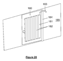
- the data centre building may be so arranged that there is at least one aisle in the rack room, the aisle being adjacent to a rack storage area, said at least one aisle including a doorway to the aisle, and an access door arrangement.
- the door arrangement may include a door movable between a closed position, closing the doorway, and an open position, allowing personnel access to the aisle.
- the access door arrangement may have a controllable air intake.
- the air intake may for example comprise a vent.
- the air intake and/or door may be arranged to move so as to scoop more or less air from an airflow.
- the air intake may be arranged to move so as to enlarge or reduce the effective cross-sectional area of one or more apertures.
- the controllable air intake may be controllable by moving the door.
- the door may be moved, whilst still closed, when varying the airflow.
- the door arrangement may include a door and a separate air-intake.
- the door may comprise the air intake.
- the building may be so arranged that, in use, cooling air flows via said doorway into or from the aisle, for example when the door is closed.
- the flow of air through the door, when in its closed position, is advantageously controllable by means of a controllable vent.
- the access door into the data room has a controllable vent, so that the door has a dual function.
- the air flow regime of the building is arranged to function with all such doors normally being closed.
- the doors are arranged to be normally closed, for example only being opened when personnel access is required.
- the door arrangement includes a door that is movable relative to the wall when the door is in its closed position to allow an air intake to scoop varying amounts of air from an air supply corridor.
- the controllable air intake controls air flow via a different part of the door arrangement than the part through which personnel can gain access.
- the door arrangement may be located on the end of a cold aisle.
- the door arrangement may be located on the end of a hot aisle, in which case it will be appreciated that the "cooling air" that passes via the door will typically have been heated by the rack-mountable electronic components.
- the door may comprise a controllable vent.
- the vent may be moveable between an open position thus allowing air to pass via the vent and a closed position.
- airflow via the vent (controllable air intake) may be restricted (preferably substantially prevented).
- the vent may comprise a row of vertical blades arranged for rotation about a vertical axis, such that the vent may be moved between closed and open positions by means of rotation of the blades.
- the blades may comprise at least one pair of adjacent blades that are arranged to rotate simultaneously in opposite directions.
- the blades are preferably arranged to rotate together to effect control of the flow of air through the vent.
- There may be two or more motors to move the blades.
- the blades preferably extend across more than 50% of the width of the door.
- the blades preferably extend across more than 50% of the height of the door.
- the effective open area when the vent is open may be greater than 1m 2 .
- the vent is preferably arranged such that in the event of a failure the vent would fail "open".
- the door arrangement preferably further comprises at least one motor for moving the controllable air intake between an open position thus allowing air to pass via the air intake and a closed position.
- the at least one motor is preferably arranged so that the amount of airflow through the door may be adjusted between three or more levels. The level of adjustment possible may be substantially continuous as between the fully closed and fully open positions.
- the door arrangement may be arranged to receive a control signal for controlling the operation of the at least one motor.
- the control signal is preferably set in dependence on measured characteristics of the air in or immediately outside the building.
- the door arrangement described above may have independent application for use within a building, not necessarily a data centre. Also, it will be appreciated that the door arrangement could be provided separately from the data centre building.
- the present invention thus further provides a door arrangement that is arranged to be fitted within a wall space, the door arrangement including a door allowing human access therethrough and a controllable air intake arranged such that the flow of air through the door, when in its closed position, is controllable by means of the controllable air intake.
- the door arrangement is preferably arranged to receive a control signal for controlling the operation of a motor provided to move the controllable air intake.
- the one or more controllable air circulation systems may be arranged to cause circulation of cooling air to rack storage areas under a controlled pressure regime.
- An air circulation control unit may be provided to control such a process.
- Pressure sensors may for example be provided to provide a measure of pressure in different regions of the data centre.
- the control unit may be arranged to receive signals representative of the pressure so measured, such signals being used to control the cooling of the data centre.
- the cooling and/or the pressure regime may of course be adjusted by means of controlling (automatically) the controllable air intake of the access door arrangement mentioned above.
- the data centre building may include an airlock room to facilitate control of the pressure regime.
- the airlock room may allow access to a rack room, whilst maintaining the controlled pressure regime.
- the pressure regime may comprise maintaining differential pressures as between the pressure in a cold aisle and the pressure in a hot aisle, so that air flow is encouraged from the cold aisle to the hot aisle.
- the pressure regime may comprise maintaining differential pressures as between the pressure in a hot aisle and a downstream pressure, for example outside the building, to encourage extraction of air away from the hot aisle.
- the pressure regime may comprise maintaining differential pressures as between the pressure in a cold aisle and an upstream air duct or corridor.
- the differential pressure may be required upstream of a cold aisle simply to enable differential pressures downstream.
- the pressure differential between two successive points on the airflow route (for example either side of the racks or either side of an air intake dividing a rack room from an airflow) is preferably greater than 10 Pa, and preferably less than 100Pa.
- the airlock room preferably comprises two doors, one door allowing entry into the airlock room from a location outside of the area of controlled pressure regime and another door allowing entry into the area of controlled pressure regime.
- an electronic control unit prevents the two doors from both being open at the same time during normal operation of the data centre.
- the control unit may for example allow the two doors to be open at the same time in the event of an emergency.
- the building may include a corridor that allows access between the airlock room and another room, for example a rack room. Such a corridor may also be arranged to allow passage of cooling air, for example to a rack room.
- the rack may be a predominantly metal rack.
- the metal rack includes insulation to reduce conduction and/or convection of heat from the hot region to the cold region. It has been found that adding a thermal insulating layer to shield the metal framework of the racks can significantly improve the thermal efficiency of the building. This is thought to be as a result of the surprisingly high effects of conduction of heat from the hot region, for example a hot aisle to the cold region, for example a cold aisle by means of conduction through the metal frame.
- the racks are thermally insulated to prevent, or at least significantly reduce, (reverse) conduction of heat from the hot aisle to the cold aisle.
- the metal rack may include uprights, which extend along the lateral edges of the rack.
- the insulation preferably extends to cover the uprights.
- the rack will of course, in use, include one or more rack-mountable electronic components. In such a case, the insulation preferably covers substantially the whole of the front of the rack, apart from those regions occupied by the one or more rack-mountable electronic components.
- the insulation is preferably arranged so that slots in the rack for mounting of rack-mountable electronic components may be selectively covered (by insulating material) or exposed to allow insertion of an IT component (server blade for example).
- the insulation may comprise a facing that extends across the front of the rack, wherein the facing includes a plurality of removable strips.
- each strip may be removably mounted to allow (on removal of the strip) for insertion of a rack-mountable electronic component into the rack.
- the insulation may comprise a portion that extends across at least one of the two sides of the rack.
- the rear of the rack may be open.
- the rack may additionally or alternatively include one or more blanking plates. For example, a blanking plate may be associated with each slot and a removable strip may also be associated with each slot.
- Such blanking plates may assist in reducing conduction of heat from the hot aisle to the cold aisle, but may also additionally or alternatively provide a better physical seal between the hot and cold aisles and thereby restrict convection of heat from the hot aisle to the cold aisle. Sealing the gaps that might otherwise exist in the area of the racks is important because otherwise cooling air may pass from one side of the racks to the other via such gaps thereby bypassing the rack-mountable electronic components which require cooling. Convection of heat from the hot aisle to the cold aisle may also be reduced by means of removably mounted vertical blanking strips filling the gap that might otherwise exist between adjacent racks. Such means may also assist in entraining air-flow through and/or directly over and around the rack-mountable electronic components.
- One or more cables may pass via the boundary between adjacent racks.
- the racks may advantageously include an aperture on each side to allow for passage of such cables.
- the aperture may be defined simply be means of the space between the front and rear vertical supports on one side of a rack, and the structure on the side of the rack may for example be substantially open.
- the one or more controllable air circulation systems may form part of a single air cooling system with built in redundancy for ensuring continued operation of the data centre building in the event of failure of one of the parts of the air cooling system.
- the single air cooling system may be in the form of a separate module, as described in more detail below.
- the single air cooling system may for example comprise a multiplicity of fans including at least one fan more than necessary (at least N+1 redundancy).
- the air cooling system may include an active refrigerant-based cooling unit (possibly one only or possibly two for the sake of redundancy).
- the air cooling system may include a mechanical cooling unit for cooling air before it is used to cool equipment in the rack rooms.
- the mechanical cooling unit may comprise an air conditioning unit, for example having DX refrigeration coils.
- the mechanical cooling unit may comprise a non-refrigerant based cooling apparatus, for example a humidification unit, an evaporative cooling unit and/or an adiabatic cooling unit. Redundancy may be provided in the air circulation system by means of being designed for primary operation without refrigerant-based cooling.
- a non-refrigerant based cooling apparatus for example a humidification unit, an evaporative cooling unit and/or an adiabatic cooling unit. Redundancy may be provided in the air circulation system by means of being designed for primary operation without refrigerant-based cooling.
- the use of ambient air from outside the building can be used to cool the racks, provided that the temperature is below a maximum threshold temperature (for example 37 degrees Celsius).
- a maximum threshold temperature for example 37 degrees Celsius
- Use of ambient air, as the cooling air can be sufficient (for example when utilising embodiments of the present invention in which ambient air is treated via a humidity-based cooling unit) for at least 97% of the duration of the operation of the data centre in certain climates.
- the data centre building may offer sufficiently robust and continuous operation without requiring two independent active refrigerant-based cooling systems (of the type requiring mechanical DX cooling, condensers, compressors, and the like).
- the data centre building is preferably formed from a plurality of separate modules.
- One of the modules may be in the form of a rack room module accommodating a rack room.
- the rack room may include a plurality of racks in which a plurality of rack-mountable electronic components are housed.
- One of the modules may be in the form of an air circulation module.
- the air circulation module may accommodate one or more air circulation systems for transporting cooling air to a rack room.
- the air circulation module may include a multiplicity (for example four or more) of fans.
- the air circulation module may include an active refrigerant-based cooling unit (preferably one only) for cooling air before it is used to cool equipment in the rack rooms.
- the air circulation module may comprise one or more mechanical cooling units.
- Each rack room module may include a cooling air duct for transporting cooling air transported from an air circulation module to the rack room. Such a cooling air duct may extend from one side of the rack room module to an opposite side.
- One of the modules may be in the form of a services plant module.
- the services plant module may comprise power plant equipment.
- the services plant module may comprise fire suppression equipment.
- the services plant module may comprise control equipment for controlling cooling and powering of IT equipment in one or more rack rooms.
- the power plant equipment (in the services plant module) may include an uninterruptible power supply (UPS), for example including a battery back-up unit.
- the power plant equipment may include switchgear equipment.
- the power plant equipment may include electrical distribution equipment.
- One of the modules may be in the form of a personnel module.
- the personnel module may be arranged to provide secure access to the data centre building.
- the personnel module may include office space.
- the personnel module may include an airlock room.
- the personnel module may include a door providing access to one or more data rooms.
- One module, not itself being a rack room, may define a cold aisle, or more preferably a hot aisle, adjacent to a rack storage area in a rack room.
- the services plant module (comprising the power plant equipment) includes a hot aisle, such that a corridor of the services plant module acts, in use, as an exhaust duct.
- the data centre building preferably comprises at least one rack room module, at least one air circulation module, and at least one services plant module.
- one air circulation module serves many rack room modules. Providing a data centre building in which a single air circulation module is able to serve more than one rack room modules enables a data centre building to be constructed having one or relatively few rack room modules and then adding further rack room modules as demand for IT capacity grows, without requiring the addition of an extra air circulation module. It will therefore be appreciated that there may be advantages to providing a data centre building having one or more rack room modules, and one or more air circulation modules, wherein all of the one or more air circulation modules have the capacity to cool more than all of the one or more rack room modules.
- the one or more air circulation modules may have the capacity to cool at least twice as many rack room modules as are provided.
- the one or more air circulation modules may have more than three times the required capacity.
- each single rack room may have a cooling requirement of at least 10kW, or at least 50kW.
- Some data centre designs may have rack rooms each having a cooling requirement of greater than 150kW.
- a single air circulation module may have a cooling capacity of more than 200kW, and possibly more than 300kW, thus allowing for future expansion.
- Each module may have a similar construction.
- Each module may comprise a frame structure having a rigid base from which there extends a multiplicity of vertical structural support columns.
- the frame structure may include two or more beams at the top of the frame each extending between a pair of the vertical support columns.
- the base may comprise a steel frame.
- the steel frame may be formed by means of a plurality of I-beams.
- the base may be formed from concrete supported on a steel framework or sheeting.
- the module may comprise a roof section.
- the base may comprise a timber floor fixed onto a frame.
- the base may be formed from board material supported on joists.
- the joists may be metal.
- Each module preferably has a length greater than 10 metres.
- Each module preferably has a length less than 20 metres.
- Each module preferably has a height greater than 2 metres. Each module preferably has a height less than 4.2 metres. Each module preferably has a width greater than 2.5 metres. Each module preferably has a width less than 5 metres.
- a module may include a wall extending upwards from at least one edge of the base.
- a module may have a base having an edge extending between two corners of the base, such that the edge (or at least a part of it) is not associated with a wall, thus defining a substantially open face of the module.
- the module may have an open face to cooperate with a corresponding open face of an adjacent module in a building, so that an open space (for example as part of a room or corridor of the building) is defined partly by one module and partly by an adjacent module.
- Each module is preferably shaped so as to be suitable for transportation by road.
- Each module preferably includes structure configured to allow the module to be lifted by, for example, a fork-lift.
- the gap is preferably between 2.5mm and 50mm, preferably between 5mm and 20mm.
- the gap between adjacent modules is preferably filled with one or more sealing strips.
- the sealing strip may be metal.
- the present invention also provides a method of cooling electronic equipment in a data centre building.
- the method may comprise a step of providing and then operating a data centre building according to the present invention as described or claimed herein.
- the method may include a step of cooling racks of items of electronic equipment by operating one or more air circulation devices to transport air above the floor via at least one access corridor, providing access to the racks.
- the method may include a step of removing air from the racks.
- the method may cause the removed air to be exhausted directly to the exterior of the building.
- the method may cause the removed air to pass via an access corridor.
- the access corridor preferably extends from a location outside of the rack room to a location inside the rack room.
- the access corridor may comprise a door.
- the access corridor need not be straight.
- the air circulation devices may use one or more fans to push air through the building.
- the one or more exhausts may therefore be passive exhausts, in that the exhausts do not themselves assist extraction of air from the building.
- the passive exhausts may include one or more controllable vents.
- the method may include a step of cooling racks of items of electronic equipment by operating one or more air circulation devices to transport air from outside the building at ambient air temperature to the racks, preferably without utilising refrigerant-based active cooling.
- the air may then be removed from the racks and exhausted to outside the building via at least one air exhaust.
- the one or more air circulation devices may be provided upstream of the racks.
- the one or more air circulation devices preferably provide a sufficient pressure differential, as compared to the air pressure immediately outside the building, to be able independently to cause air to be exhausted out of said at least one exhaust at a rate of at least 10m 3 s -1 per rack room (or optionally at least 8 m 3 s -1 per rack room, or optionally at least 5m 3 s -1 per rack room).
- the data centre building may be arranged to operate at low IT demand levels with exhaust rates of the order of only 0.3m 3 s -1 per rack room.
- air may be exhausted at a rate of at least 50m 3 s -1 from the building (or floor of the building, as the case may be), when operating at high demand for example.
- air may be exhausted out of said at least one exhaust at a rate of at least 0.4m 3 s -1 per rack.
- air may be exhausted out of said at least one exhaust at a rate of at least 0.002m 3 s -1 per slot in the racks in the room. If there are 40 racks in a rack room and 40 slots per rack, such a rate would be equivalent to about 3.2m 3 s -1 per rack room. Alternatively or additionally, air may be exhausted out of said at least one exhaust at a rate of at least 0.005m 3 s -1 per rack slot, preferably at a rate of at least 0.008m 3 s -1 per rack slot.
- the air may be exhausted out of said at least one exhaust at a rate of as little as 0.00024m 3 s -1 per rack slot. If there are 24 racks in a rack room and 40 slots per rack (of which at any given time 10 or more are each closed over by a blanking strip thereby restricting or preventing the flow of air therethrough), such a rate may be equivalent to less than 0.2m 3 s -1 per rack room. Air may be exhausted out of said at least one exhaust at a rate of at least 0.01m 3 s -1 per rack slot, or possibly at least 0.15m 3 s -1 per rack slot (such rates again representing the higher end of the range of likely operational exhaust rates).
- a sufficiently large volume of air per second is used to effect "ambient air" cooling of the IT equipment in the data room.
- refrigerant-based active cooling there may therefore be less of a need for use of refrigerant-based active cooling.
- this means of cooling may be used even when the ambient air temperature outside is higher than 20 degrees Celsius.
- the method includes a step of operating the data centre and cooling it by means of airflows where the rate of exhaust is greater than 5m 3 s -1 per rack room and also a step, performed at a different time, of operating the data centre and cooling it by means of airflows where the rate of exhaust is less than 1m 3 s -1 per rack room.
- each rack room may be fewer exhausts than there are rack rooms. There may be at least 10 racks per room, preferably more than 20 racks per room. Each building may include more than two rack rooms. Preferably, however, there are fewer than ten data rooms/rack rooms per floor of the building. Each rack may have more than 10 slots for insertion of separate IT equipment units. Each rack may have more than twenty such slots. Thus, each rack room may, when operating at full capacity, accommodate over 500 separate equipment units, and possibly more than 1,000.
- the method may extract heat at a rate of at least 5kw per rack room module, or optionally at a rate of at least 10kw per rack room module.
- the method may extract heat at a rate of at least 50kw per rack room module, and possibly at a rate of at least 80kw per rack room module. Such heat extraction rates may be achieved solely with ambient air cooling.
- the method may additionally include a step of detecting fire or smoke.
- the method may include a step of ceasing transport of air from outside the building. Such a step may be conducted under the control of a fire suppression control unit.
- the method may also include a step of closing the one or more air exhausts.
- the method may include a step, in the event that fire or smoke is detected, of causing cooling air to be re-circulated.
- the items of electronic equipment may be cooled by operating the one or more air circulation devices to transport air from within the building, to the racks and then from the racks back to the air circulation devices, with an optional step of cooling the air (for example by means of mechanical cooling equipment).
- a fire suppression control unit may then be able to discern whether the fire/smoke previously detected was from outside the building or inside the building. If fire or smoke continues to be detected, then appropriate action may be taken. For example, fire suppression gas may be released into the data centre building.
- Embodiments of the present invention enable rapid deployment of fire suppression gas throughout the data centre building as a result of the large volume of air/gas that is able to flow through the building per second.
- the present invention yet further provides a method of building a data centre building.
- the data centre building so built may be in the form of a data centre building according to the present invention as described or claimed herein.
- the method of building the data centre building may comprise a step of extending an existing modular data centre building, in which there is provided at least one rack room module accommodating a rack room having a plurality of racks in which a plurality of rack-mountable electronic components are housed.
- Each rack room module may include a cooling air duct for transporting such cooling air from the air circulation module to the rack room, the cooling air duct extending from one side of the rack room module to an opposite side.
- the step of extending an existing modular data centre building is advantageously conducted whilst the plurality of rack-mountable electronic components in each rack room of the existing building are operated and cooled by means of air from said at least one air circulation module.
- the method may include a step of adding a further (new) rack room module accommodating a rack room and having a cooling air duct extending from one side of the rack room module to an opposite side, such that an end of the cooling air duct on one side of the further (new) rack room module is aligned with an end of the cooling air duct on one side of a rack room module of the existing modular data centre building.
- the method may then include a step of connecting the cooling air duct of the further (new) rack room module with the cooling air duct of the rack room module of the existing modular data centre building.
- the method may include a step of removing an end portion of the building (for example a further module, optionally in the form of a personnel module) from the end of the existing data centre building to expose the side of the rack room module at the end of the existing building to which the extension is to be added.
- the method may include a step of blocking off an end of the cooling air duct of the rack room module of the existing modular data centre building before such an end portion of the building is removed.
- the invention also provides a rack room building module for building a data centre installation, wherein the module comprises:
- the rack room building module comprises a steel frame having the dimensions of an ISO shipping container. It may be constructed so as to be suitable for transporting as a shipping container.
- this embodiment of the invention may be used both in easily accessible areas such as city centres and in remote areas.
- the present invention further provides a method of constructing a data centre in a building.
- the method may include the steps of:
- the method provides a data centre that can be used in locations where the construction of a new building may not be possible or desirable, such as in city centres.
- the method may also be used by an organisation with an existing data centre or data room to easily upgrade the existing data centre or data room to use the present invention, thereby improving its efficiency.
- it may be used in a building that has been purpose-built to accommodate a data centre constructed according to the method.
- the present invention also provides a kit of parts for constructing a data centre in a space within a building, wherein the kit includes at least one partition arranged for installation in the space such that the partition(s) and the space cooperate so as to define:
- Figure 2 shows a data centre building 10.
- the building 10 is rectangular with external walls 12.
- the building is divided into front and rear sections by an internal dividing wall 12a, located approximately one third of the length of the building from the rear external wall.
- the rear section (on the left in Figure 2 ) defines an air optimisation room 11, which provides a system of circulating cooling air in the building 10.
- Ambient air (represented by the light arrow 18) can enter the air optimisation room 11 through an ambient air intake 13 in the rear external wall.
- Ambient air 18 can be treated/cooled in the air optimiser room and this air 18a is then used for cooling. If the ambient air outside the building 10 is sufficiently cool, the ambient air may be used as cooling air, without requiring any active refrigerant-based cooling by the air optimisation room 11. Cooling air 18a passes into the front section of the building 10 through a controllable vent 17 in the internal dividing wall 12a.
- the front section (on the right in Figure 2 ) of the building 10 defines a rack room 19.
- the rack room 19 houses two rows of racks 14.
- the racks 14 extend away from the internal dividing wall 12a, towards the front of the building.
- Each rack row extends approximately out to two thirds of the length of the front section of the building.
- there are 20 racks in each row each rack housing up to 40 items of IT equipment (typically server blades). There may therefore be as many as 1,600 items of IT equipment in the racks.
- a blanking panel 14a extends between the front ends of the two rows of racks, thereby defining a cold region 19a between the internal dividing wall 12a, the two racks 14 and the blanking panel 14a.
- a hot region 19b is defined on the other side of the racks 14 and the blanking panel 14a. Air can escape from the hot region 19b though a hot air exit 15 in the front external wall of the building.
- ambient air 18 enters the air optimisation room 11 through the ambient air intake 13.
- the ambient air 18 is cooled/treated as necessary in the air optimisation room 11 resulting in cooling air 18a, which enters the rack room 19, into the cold region 19a, via the vent 17.
- the cooling air 18a moves over the racks 14 in the rack room 19 to reach the hot region 19b and in the process cools the racks 14.
- the resulting hot air (indicated by dark arrows 16) coming off the racks 14 then leaves the rack room through the hot air exit 15. It will of course be appreciated that the hot air 16 is simply the result of the cooling air 18a having been heated by the equipment in the racks 14 and is otherwise essentially the same air.
- the operation may be considered as involving the flow of cooling air into the rack room 19, the flow of cooling air via the racks 14 and then the flow of cooling air (then heated by the racks such that the "cooling air” may then have less, if any, ability to cool) out of the rack room.
- hot air or “exhaust air” can be considered as heated or used "cooling air”.
- air upstream of the racks is indicated by light arrows and downstream or exhaust air is indicated by dark arrows.
- the volume of air flow through the building may, during certain conditions for example when outside temperature is relatively high and/or IT loads are relatively high, be at least 12m 3 s -1 .
- the air optimiser module has the capacity to generate air flow through the building at a rate as high as at least 40m 3 s -1 (i.e. more than about 1m 3 s -1 per rack and about 0.025m 3 s -1 per rack slot, assuming that substantially all air flowing through the building passes via a rack slot).
- the volume of air flow through the building may during other occasions be about 0.3m 3 s -1 , during certain conditions. Such a rate of supply of air may still be sufficient to cool the IT equipment in the single rack room of the building by means of ambient air cooling alone for ambient air temperatures of up to 24 degrees Celsius.
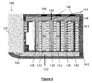
- Figure 3 shows a rectangular data centre building 100 with external walls 110 and a flat roof of a further embodiment.
- a hole in the external wall defining an entrance 111.
- a second hole in the external wall defining a fire exit 112.
- a hole defining an ambient air intake hole 113 (not visible).
- a hole defining a hot air outlet hole 114 In front of the fire exit 112 but also on the right side of the building is a hole defining a hot air outlet hole 114.
- the data centre building 100 is made up of four rectangular modules that are placed side to side so that the long sides of the rectangular modules are adjacent each other.
- the ends of the rectangular modules form the external side walls of the building.
- the external walls of the modules are formed from steel frames that are welded and bolted.
- the floor of the modules is formed from steel frames and joists.
- the floor panels additionally have timber floorboards.
- the roof is constructed from a suitable weatherproof panel system and watertight membrane, including falls to one side of the roof and external drainage collection.
- the wall panels of the modules are formed from highly insulated steel panels, with a fire resistance of at least one hour.
- the wall and roof panels may also be constructed with magnetic shielding, RF or X-ray protection.
- the internal finish of the walls and ceiling is a plastic coated galvanised steel finish.
- the modules are connected to each other by using modular wiring systems or quick disconnects on mechanical pipework. Hence, the modules can be easily connected and disconnected from each other.
- an air optimisation module 120 located at the rear of the building 100, a plant room module 130 located in front of the air optimisation module 120, a rack room module 140 located in front of the plant room module 130 and a personnel module, here in the form of an entry module 150, located in front of the rack room module 140, at the front of the building 100.
- the air optimisation module 120 shown most clearly in Figure 5 , includes the rear external wall of the building 100 and the rearmost parts of the left and right side walls of the building.
- the air optimisation module 120 contains an air optimisation unit 122 located at the rear, right corner of the building.
- the air optimisation unit 122 is located adjacent the external right side wall of the building 100 so that an ambient air intake grille 121 (not visible) on one end of the unit 122 lines up with the ambient air intake hole 113.
- the ambient air intake grille 121 includes vents that are controllable so that the amount of air entering the air optimisation unit 122 through grille 121 can be controlled.
- the air optimisation unit 122 also has a second air intake in the form of a return air grille 125.
- the return air grille 125 is located at the right, front end of the optimisation unit 122, near the end wall including the ambient air intake grille 121.
- the return air grille 125 includes vents that are controllable so that the amount of air entering the air optimisation unit 122 through grille 125 can be controlled.
- the air optimisation unit 122 contains various air treatment apparatus, including banks of fans, air filters, humidification apparatus and an active DX cooling system.
- the DX cooling system includes soft copper refrigeration pipework.
- the humidification apparatus is used to provide adiabatic cooling during use.
- the air optimisation unit 122 also contains an air mixing box (not shown) for mixing the air from return air grille 125 and ambient air intake grille 121.
- the unit 122 also contains sound attenuation apparatus.
- the air supply corridor 123 runs from the rear external wall, and along and in between the left side of the air optimisation unit 122 and the left external side wall.
- a curved wall 124 is located in the rear, left corner of the building to help direct air from the air optimisation unit 122 along the corridor 123.
- the floor of the air optimisation unit 122 is a non-slip safety floor.
- the plant room module 130 shown most clearly in Figure 6 , includes two parts of the two external side walls of the building.
- the plant room module 130 contains a rectangular plant room 133 defined by plant room walls 134.
- the plant room 133 is located centrally along a rear side of the plant room module 130.
- the air optimisation module 120 and the plant room module 130 are joined, the plant room 133 sits against the front side of the air optimisation module 120 and the left end of the plant room 133 lines up with the left end of the air optimisation unit 122.
- plant room wall 134 is extended to the front side of the plant room module 130.
- a passageway running along and in between the left external side wall of the building and the plant room wall 134 is defined. This passageway runs along the width of the plant room module 130 and is closed off from the plant room 133 and the rest of the plant room module 130 by the plant room walls 134.
- the passageway joins up with and forms part of the air supply corridor 123.
- a hot air corridor 132 running along the width of the plant room module 130 and along the external side wall of the building containing the fire exit 112.
- the plant room module 130 contains a fire exit door 135 over the fire exit 112.
- the hot air corridor 132 also extends around the front of the plant room 133, in between the front plant room wall 134 and the front of the plant room module 130. This corridor extends up to the right side of the extended plant room wall 134. This allows air from the rack room module 140 (located in front of the plant room module 130) to enter the hot air corridor 132.
- a plant room access door 131 On the left end wall of the plant room 133 is a plant room access door 131.
- the door 131 allows access to the plant room 133 from the hot air corridor 132.
- the plant room 133 contains various apparatus, including fire suppression gas discharge canisters 136 and associated manifold and valves, a power metering panel 137a for monitoring the power consumed by each rack in the rack room module 140, a dual electrical distribution panel 138, an uninterruptable power supply 139a and back-up batteries 139b. These apparatus are mounted on the internal sides of the plant room walls 134.
- the plant room 133 also contains a process control panel 137b, including a VESDA (Very Early Warning Smoke Detection Apparatus) fire detection monitoring panel, mounted on an internal side of the plant room walls 134.
- the process control panel 137b receives data from various sensors including sensors in the rack room module 140 and an outside ambient air temperature sensor. This outside ambient air temperature sensor may be placed outside the building 100 or just inside the building 100, near the ambient air intake grille 121. It uses this information to control the fans, humidification apparatus, cooling system and controllable vents in the building in order to achieve effective cooling of the racks in the rack room module 140.
- VESDA Very Early Warning Smoke Detection Apparatus
- the fire suppression gas discharge canisters 136 are connected to the air optimisation unit 122 so that in the event of a fire (when the VESDA monitoring panel is triggered), gas from the canisters 136 can be discharged through the air optimisation unit 122 into air supply corridor 123.
- the uninterruptable power supply 139a and back-up batteries 139b are designed to provide 10 minutes of power in the event of failure of an external power supply.
- the batteries are provided with their own dedicated cooling system.
- the floor of the plant room 133 is a non-slip safety floor.
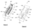
- the rack room module 140 shown most clearly in Figure 7 , includes parts of the external side walls of the building.
- the rack room module 140 contains two elongate rectangular rack storage areas, the areas being parallel to each other. The areas are together positioned centrally along a rear side of the rack room module 140. At the left end of the rack storage areas is an internal wall 141 running along the width of the rack room module 140. When the plant room module 130 and the rack room module 140 are joined, the rack storage areas sit against the plant room module 130 and the internal wall 141 lines up with the left end of the air optimisation unit 122 and left wall 134 of the plant room 133.
- a passageway running along and in between the left external side wall of the building and the internal wall 141 is defined.
- This passageway runs along the width of the rack room module 140 and is closed off from the rack room area and the rest of the rack room module 140 by the internal wall 141.
- the passageway joins up with and forms part of the air supply corridor 123.
- Each rack storage area is effectively defined by a single row of racks 143 running lengthways along the rack room module 140, i.e. widthways across the building, from the internal wall 141 to the right end of the rack room area.
- the two rows of racks 143 are separated by a cold aisle 144.
- a cold aisle blanking panel 147 designed to close off the cold aisle 144 at the right end.
- over-rack blanking plates 148 designed to stop cold air travelling over the racks 143 between the top of the racks and the ceiling of the rack room module 140. Hence, air can only leave the cold aisle 144 through the racks 143. There is no personnel access possible from the cold aisle 144 directly to the other side of the racks 143.
- Air from the supply air corridor 123 can enter the cold aisle 144 through cooling air intake grille 142, located on the internal wall 141 in between the rows of racks 143.
- the grille 142 includes vents that are controllable by the process control panel 137b so that a desired air pressure regime can be achieved.
- the cooling air intake grille 142 is part of a securable door that can be opened and closed to allow personnel access from the air supply corridor 123 to the cold aisle 144 of the rack room module 140.
- the cooling air intake grille door 142 is made from aluminium and/or steel.
- the rearmost row of racks 143 is located adjacent the passageway in the plant room module 130 that joins up with the hot air corridor 132. Hence, hot air coming from the rearmost rack 143 is directed to the hot air corridor 132 via this passageway.
- the passageway is defined as a hot aisle 145.
- the passageway is also defined as a hot aisle 145.
- a hot air outlet grille 146 On the right end wall of the rack room module 140 is a hot air outlet grille 146 corresponding to the hot air outlet hole 114.
- the grille 146 has vents that are controllable by the process control panel 137b so that the amount of hot air 16 that is exhausted from the building 100 through hot air outlet grill 146 can be controlled.
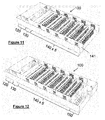
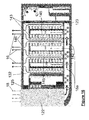
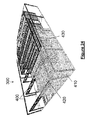
- FIG 18 shows a row of racks 143 in more detail.
- the rack frames 143a are made of metal.
- Each rack is an open fronted 42u standard universally compatible server rack.
- the racks are joined together in rows by filler pieces 143c.
- the filler pieces can be a plain infill panel, a vented infill panel (including a mesh panel on the filler piece), a power distribution support infill panel or a cable management infill panel. It is preferred for the filler pieces 143c to be in the form of vertically extending blanking strips that seal the racks and thereby restrict undesirable heat convection. Cables are run vertically to the top of the racks through the cable management panels and guided through cable trays (not shown) at the top of the racks.
- Cables can then be run down one side of the row of racks 143 in cable trough 143d. Hence, the cable is kept out of the air flow and this improves efficiency.
- a gasket seal 143e is provided around the top of the racks 143 to provide a seal against air flow.
- Each rack is fitted with a "42u" insulation strip.
- the insulation strip is made up of individual blanking strips 143b that can be removed from the racks.
- Each individual blanking strip 143b corresponds in height to the height of each unit space on the rack.
- individual blanking strips 143b can be placed on the racks to cover any area not occupied by electronic components in the racks.
- the strips 143b can be removed to allow additional electrical components to be inserted in the racks 143.
- the strips 143b reduce the conduction of heat from the hot aisles 145 to the cold aisle 144.
- Insulation material is also placed on the over-rack blanking plates 148 and cold aisle blanking panel 147 (not shown in Figure 18 ).
- the metal rack includes a thermally insulating barrier that reduces flow of heat from the hot aisle to the cold aisle via heat conduction across the metal rack.
- a floor 149 of the rack room module 140 has an anti-static vinyl covering.
- the rack room module 140 also contains sensors for measuring the air temperature, humidity level, pressure and air flow. These sensors are connected to the process control panel 137b in the plant room 133.
- the entry module 150 shown most clearly in Figure 8 , includes the front external wall and the foremost parts of the external side walls of the building.
- the entry module 150 has an entry portal 151 located adjacent the entrance 111 to the building 100.
- the entry portal 151 is a semi-circular door surrounding the entrance 111 to the building. Hence, upon entering the building, personnel pass through the entrance door 111 into a semi-circular space defined by the entry portal 151 and then through the semi-circular entry portal 151 itself.
- the entry module 150 also has a security/reception area 152, located to the left and to the rear of the entry portal 151.
- a storage and IT staging room 153 On the right side of the entry module, in the front right corner of the building 100, is a storage and IT staging room 153, accessed through a door 154. To the rear of the storage and IT staging room 153, located in the right, rear corner of the entry module 150, is an air lock room 155. The air lock room 155 is accessed from the security/reception area 152 through an air lock access door 156. An air supply corridor access door 157, adjacent the right side wall of the building, provides access from the air lock room 155 to the air supply corridor 123 of the rack room module 140.
- the air supply corridor access door 157 can only be opened when the air lock access door 156 is closed. Similarly, the air lock access door 156 can only be opened when the air supply corridor access door 157 is closed. Hence, loss of air pressure of the air supply corridor can be reduced, while still allowing personnel access to the air supply corridor 123 and cold aisle 144, through the door of the cooling air intake grille 142.
- the entry module 150 On the rear side of the entry module 150 are two central windows 158 allowing personnel in the entry module 150 to see into the rack room module 140.
- a hot air corridor access door 159 In the right, rear corner of the entry module 150 is a hot air corridor access door 159.
- This door 159 links up to the hot air corridor 132 of the rack room module 140 and hence allows personnel access to the hot air corridor 132, the rear of the racks 143 facing the hot aisles 145 and the plant room 133, through plant room access door 131.
- the floor of the entry module 150 is a non-slip safety floor.
- the plant room 133 and the entry module 150 contain their own heating and ventilation system that is not connected to the supply of air from the air optimisation unit 122.
- the heating system includes an electric panel heater with an integral thermostat.
- All external doors of the building 100 i.e. entrance 111 and fire exit door 135) are made from aluminium or steel.
- the doors can contain double glazed window panels.
- Figure 4 shows a data centre building 100, similar to that shown in Figure 3 .
- the building of Figure 4 has three rack room modules 140.
- Each rack room module 140 is identical.
- a building 100 is provided that can accommodate more racks 143.
- Cooling air 18a from the air supply corridor 123 can enter the cold aisle 144 of each rack room module 140 through the controlled vents of the cooling air intake grilles 142.
- the hot air 16 from the racks 143 can leave the rack room modules 140 through hot aisles 145 in between the racks 143.
- the hot air 16 then reaches the hot air corridor 132, as before.
- Figure 9 shows a data centre building with an air optimisation module 120, a plant room module 130, an entry module 150 and two rack room modules 140.
- Figure 10 shows that the entry module 150 of the building 100 of Figure 9 can be removed to leave the front of the second rack room module 140 exposed.
- a blocking panel 141a is placed over then front end of the air supply corridor 123 to reduce loss of air supply pressure.
- Figure 11 shows that three (or any number) of additional rack room modules 140 can be placed next to the existing rack room modules 140 such that the internal walls 141 line up to create a lengthened air supply corridor 123.
- the building of Figure 11 contains an air optimisation module 120, a plant room module 130 and five connected rack room modules 140.
- Figure 12 shows that the entry module 150 removed from the building 100 of Figure 9 can be replaced next to the foremost rack room module 140 of Figure 11 .
- the building of Figure 9 can be expanded from having two rack room modules 140 to having five rack room modules 140.
- the expansion of data centre buildings 100 can be conducted whilst the electronic components in each rack 143 of the existing rack room modules 140 are operated and cooled by cooling air 18a from the air supply corridor 123. Such a process is referred to elsewhere in this document as a "hot add" process.
- Figure 13 shows a multi-storey data centre building 100.
- the building 100 has three storeys stacked on top of each other.
- Each storey is made up of an air optimisation module 120, a plant room module 130, three rack room modules 140 and an entry module 150.
- the particular type of modular construction employed by this embodiment lends itself to a fully scalable, and very flexible, data centre construction method.
- each storey includes a stair module 160 placed in front of the entry module 150, on the right hand side.
- Each stair module 160 is rectangular with a height identical to the entry module 150 and the rest of the modules, a width similar to the entry module 150 and a length of about half that of the entry module 150.
- Each stair module 160 has an exit door 163 (visible for third storey only) on the left rear corner of the module 160 such that the exit door 163 lines up with and allows access to the entry portal 151 of the entry module 150. Hence, the exit door 163 of each stair module 160 allows access to the entry module 150 on the respective level.
- Each stair module 160 also contains a set of stairs 162 extending from the bottom of the stair module 160 to the top of the stair module 160. Hence the stairs 162 allow personnel to move up to the entry module 150 above.
- the lowermost (first) storey stair module 160 also has an entry door 161 located on the left side of the front wall of the stair module 160 to allow personnel access to the building 100.
- any or all of the above described embodiments may not include an entry module 150.
- the front side of the foremost rack room module 140 is enclosed by an external front wall.
- the external front wall should include an air supply corridor access door on the left hand side to allow access to the air supply corridor 123 and a hot air corridor access door on the right hand side to allow access to the hot air corridor 132.
- the data centre building 100 of any of Figures 3 , 4 , 9 , 12 or 13 operates to cool the racks 143 in the rack room module(s) 140 by generating a sufficient quantity, velocity and pressure of cooling air 18a in the air optimisation unit 122.
- the air optimisation unit 122 also filters the air using air filters and performs humidification / de-humidification on the air, as necessary.
- the cooling air 18a is pushed out of the air optimisation unit 122, directed by the curved wall 124 and moves along the air supply corridor 123.
- the vents in the cooling air intake grille(s) 142 are controlled so as to ensure appropriate distribution of the cooling air 18a in the cold aisle(s) 144 of the rack room module(s) 140 in dependence on the cooling requirements of the IT equipment in the racks associated with each cold aisle (which may for example be measured by temperature sensors at the rear of the racks).
- the cooling air 18a is drawn across the racks in the rack room module(s) 140 by the integral fans in the electrical components in the racks and cools the electrical components.
- the resulting hot air 16 moves through the hot aisles 145 in the rack room module(s) 140 and plant room module 130 to the hot air corridor 132.
- the pressure differential between the cooling air 18a and the hot air 16 is maintained at a sufficient level to ensure there is no return of hot air 16 through the racks. This is done by monitoring the amount of air flow in the rack room module 140 using the air flow sensor. The amount of air flow is fed to the process control panel 137b in the plant room 133.
- the process control panel 137b then controls the fans in the air optimisation unit 122 and the various controllable vents in the building (apart from the vents 142 in the data room doors, which are used to control the amount of cooling air fed to each cold aisle) so that satisfactory air pressure is delivered to the air supply corridor 123 to give a satisfactory air pressure differential and air flow in the rack room module 140.
- the humidity of the air in the rack room module 140 is monitored by the humidity level sensor and fed to the process control panel 137b.
- the process control panel 137b then controls the humidification apparatus in the air optimisation unit 122 so that satisfactory air humidity is delivered.
- the building 100 operates differently depending on the temperature of the outside ambient air. This is done in order to allow the cooling air 18a to be between 18°C and 24°C, whilst minimising the amount of refrigerant-based mechanical cooling that needs to be performed on the air by the cooling system in the air optimisation unit 122.
- the process control panel 137b controls the cooling system in the air optimisation unit 122 so that the cooling system is turned off.
- the process control panel 137b also controls the vents in the return air grille 125 so that the vents on the grille 125 are open. This allows some of the hot air 16 in the hot air corridor 132 to re-enter the air optimisation unit 122. The rest of the hot air 16 escapes out of the building 100 through hot air outlet grille(s) 146. I.e. there is partial extraction of ambient air 18 and partial re-circulation of hot air 16.
- the hot air 16 that re-enters the air optimisation unit 122 goes through the air mixing box (not shown) in the unit 122 and mixes with the ambient air 18 being drawn into the air optimisation unit 122 through the ambient air intake grille 121. This results in warmer than ambient air passing from the air optimisation unit 122 into the air supply corridor 123 and reaching the cold aisle(s) 144 of the rack room module(s) 140.
- the temperature of the air at the rear of each row of racks in the rack room module(s) 140 is monitored by the air temperature sensors and fed to the process control panel 137b. Pressure measurements are also taken.
- the process control panel 137b controls the vents 142 in the cold aisle doors in dependence on cooling demand and controls the fans in the air optimisation unit 122 and other vents so that a sufficient air flow is delivered from the air supply corridor 123 to the cold aisles in the rack room module(s) 140.
- the process control panel 137b controls the cooling system in the air optimisation unit 122 so that the cooling system is turned off.
- the process control panel 137b also controls the vents in the return air grille 125 so that the vents on the grille 125 are closed. This means that no hot air 16 can re-enter the air optimisation unit 122. I.e. there is no re-circulation of hot air 16 and there is total ambient air 18 extraction. All of the hot air 16 escapes out of the building 100 through hot air outlet grille(s) 146.
- the temperature of the air at the rear of each row of racks in the rack room module(s) 140 is monitored by the air temperature sensors and fed to the process control panel 137b. Pressure measurements are also taken.
- the process control panel 137b controls the vents 142 in the cold aisle doors in dependence on cooling demand and controls the fans in the air optimisation unit 122 so that a sufficient air flow is delivered from the air supply corridor 123 to the cold aisles in the rack room module(s) 140 to a satisfactory temperature.
- the process control panel 137b controls the cooling system in the air optimisation unit 122 so that the cooling system is turned on and set to cool the cooling air 18a leaving the air optimisation unit 122 down to a maximum of 24°C. This is achieved by using the humidification unit to cause adiabatic cooling of the air. At this stage no refrigerant-based active cooling is required.
- the process control panel 137b also controls the vents in the return air grille 125 so that the vents on the grille 125 are closed. This means that no hot air 16 can re-enter the air optimisation unit 122. I.e. there is no re-circulation of hot air 16 and there is total ambient air 18 extraction. All of the hot air 16 escapes out of the building 100 through hot air outlet grille(s) 146.
- the temperature of the air at the rear of each row of racks in the rack room module(s) 140 is monitored by the air temperature sensors and fed to the process control panel 137b.
- the process control panel 137b then controls the cooling air flow regime so that a sufficient air flow is delivered from the air supply corridor 123 to the cold aisles.
- the process control panel 137b controls the cooling system in the air optimisation unit 122 so that the cooling system is turned on and set to cool the cooling air 18a leaving the air optimisation unit 122 down to a maximum of 24°C. This is achieved by means of additionally using DX-mechanical (refrigerant-based) cooling.
- the process control panel 137b also controls the vents in the return air grille 125 and hot air outlet grille 146 so that the vents on the grille 125 are open and the vents on hot air outlet grille(s) 146 are closed. This ensures all the hot air 16 re-enters the air optimisation unit 122. I.e.
- the process control panel 137b also controls the vents of ambient air intake grille 121 so they are closed.
- the hot air 16 goes through the air mixing box (not shown) in the air optimisation unit 122 and is re-cooled by the cooling system in the air optimisation unit 122.
- the temperature of the air at the rear of the racks in the rack room module(s) 140 is monitored by the air temperature sensors and fed to the process control panel 137b.
- the process control panel 137b then controls the cooling air flow regime so that a sufficient air flow is delivered from the air supply corridor 123 to the cold aisles.
- the process control panel 137b activates the fire suppression gas discharge canisters 136. Hence, gas is discharged through the air optimisation unit 122 into air supply corridor 123. At the same time, the process control panel 137b closes vents in the hot air outlet grille(s) 146 and opens vents in the return air grille 125 to ensure the air inside the building 100 is re-circulated.
- the VESDA system may as an initial step cause air flow into and/or out of the building to be ceased and to operate the building in an air re-circulation mode.
- release vents (not shown) in the building 100 are activated to maintain the building integrity.
- the uninterruptable power supply 139a and back-up batteries 139b are turned on and can provide clean power to allow continuous operation of the racks 143 and other essential services for 10 minutes.
- the different modules can be individually delivered on trucks, such as 40 foot articulated or flat bed trucks.
- the buildings are typically less than 4.2m high and therefore are readily transported via road or rail.
- the modules can then be craned into place using integral lifting eyes (not shown) on the modules or using slings.
- the building 100 can be sited on a flat area of concrete. Alternatively, the building 100 can be placed on concrete blockwork if the site is not level or if the level of the building 100 is to match an existing building level.
- the building 100 is then connected to the existing site drainage system, telecommunications supply, water supply and electrical power supply. Alternatively, a supplementary power generation unit can be added.
- the building 100 can also be connected to the existing building management systems, security systems or fire alarm systems of the site.
- each module has the dimensions of an ISO shipping container and is constructed so that it may be transported as a shipping container.
- ISO shipping containers come in a range of lengths and heights but are all 2259 mm wide between the corner fittings (measured from the centre of the hole in the fitting). Common lengths are approximately 6 m, approximately 12 m and approximately 14 m.
- Each module comprises a steel framework, with the vertical parts of this framework including an integrated drainage system (not shown).
- the walls, roof and floor of each module are made of corrugated steel.
- Figure 21 shows a data centre 200 constructed from container-sized modules. It comprises an air optimisation module 220, a plant room module 230, eight rack room modules 240, and a hot aisle unit 250. An end wall of the air optimisation module 220 and an end wall of one of the rack room modules 240 have been replaced with an air intake 260 and an exhaust air outlet 270 respectively. One or more of the panels forming an external wall of the data centre 200 may include a door (not shown).
- Figure 22 is an exploded view of the data centre of Figure 21 .
- Figure 23 shows the layout of a storey of a building into which three data centres 300a, 300b and 300c according to the invention have been installed. Part 380 of the storey is not taken up by a data centre and this may be used for another purpose such as office space or storage.
- Data centres 300a and 300b each comprise two air optimisation rooms 320, two plant rooms 330, a rack room 340 and an air supply corridor 350.
- Data centre 300c comprises an air optimisation room 320, a plant room 330, a rack room 340 and an air supply corridor 350. Holes (not shown) have been made in the walls of the building to serve as intakes for outside air and outlets for exhaust air.
- Data centres 300a, 300b and 300c have been constructed by installing partitions into a space in the existing building.
- the partitions are formed using a kit of parts consisting of metal girders and insulated steel panels.
- Figure 24 shows a partially constructed data centre 300 according to this embodiment of the invention.
- a framework 400 built from the metal girders has been constructed in a space within a building.
- the space has a concrete floor.
- Wall panels 410 and ceiling panels 420 are attached to this framework.
- Panels including dampers (not shown) are positioned so as to line up with the intake and outlet holes in the exterior walls of the building.
- Ladder racks 430 are suspended above the ceiling panels 420 to support the cabling and other mechanical and electrical services that are provided to the racks.
- the panels are arranged to form a data centre having an air optimisation room, a plant room, a rack room, and an air supply corridor.
- the layout of the data centre is the same as in other embodiments of the invention.
- the rack room includes separate hot aisles and cold aisles in the same arrangement as in the other embodiments of the invention.
- the building 100 can operate in either of the first three modes of operation described for 97% of the time. Hence, for 97% of the time, the building 100 only uses ambient airflow and humidity-controlled cooling and does not need to rely on refrigerant-based cooling. This dramatically reduces the energy consumption of the data centre building 100.
- the building can still operate in the first or second mode a significant proportion of the time and therefore can use only air flow cooling. Even at temperatures of up to 37°C, the building 100 will operate in the third mode of operation and therefore can still utilise efficient means of cooling.
- PUE power usage efficiency
- This may conveniently be defined as the total energy used by the data centre divided by the energy deployed to the racks 143.
- Typical prior art data centres have a PUE of greater than 1.5.
- a data centre building 100 of the present invention could have a PUE of less than 1.2 for most parts of the world. This figure would increase for hotter parts of the world where refrigerant-based mechanical cooling has to be used more often.
- the securable door allowing personnel access from the air supply corridor 123 to the cold aisle 144 of the rack room module 140 includes an adjustable air intake means in the form of an air intake grille 142 including vents.
- the door can be configured differently to provide cooling air 18a into the cold aisle 144 via the doorway.
- Figures 19a, b , c and d show such a door 170.
- the door is mounted in a door frame 170a.
- the door frame is hinged to the internal wall 141 of the room module 140, adjacent a door hole in the internal wall, along a first side 171 of the door frame.
- the first side 171 of the door frame is the side furthest from the air optimisation unit 122.
- the door frame 170a is hinged to a first side of an air intake grille 172 along a second opposite side of the door frame.
- the grille is attached to the internal wall 141 by a hinge along a second opposite side of the grille.
- the hinge is also slidable along the internal wall 141.
- the door frame When the door frame is in an open position, as shown in Figure 19d , the door frame is hinged away from the hole in the wall 141.
- the grille pivots with respect to the door frame and by the hinge on the internal wall 141 and the internal wall hinge slides along the internal wall 141 such that the second side of the grille remains in contact with the internal wall 141 and the first side of the grille remains connected to the second side of the door frame.
- an angled path against the door and door frame and through the grille is provided for air in the air supply corridor 123.
- the door arrangement therefore acts as a variable air inlet scoop. The air thus flows from bottom to top as shown in Figures 19c and d (the air supply corridor being below the doorway in the Figures).
- the door can also be opened from the door frame in the open position, as shown in Figure 19c .
- the door frame and grille can also be positioned in a number of intermediate positions between the fully open and fully closed positions described above.
- the door arrangement could of course also be used in a reverse configuration, so that first side of the door frame is the side nearest the air optimisation unit with air flowing from the top to bottom as shown in Figures 19c and d (the air supply corridor being below the doorway in the Figures).
- FIG 20 shows yet another embodiment of a door 180 for allowing personnel access therethrough whilst also providing a means for controlling airflow through the door whilst the door is in its closed position.
- the door thus includes adjustable air intake means in the form of a vent 181 having a number of vertical blades 182 arranged in a row.
- the blades are each mounted for rotation about a vertical axis, such that the vent may be moved between closed and open positions by means of rotation of the blades.
- the blades 182 are arranged such that pairs of adjacent blades are arranged to rotate simultaneously in opposite directions. Having such an arrangement facilitates better control of the air-flow in comparison to the case where all blades rotate in the same direction.
- Two motors are arranged to move the blades 182, one motor for the odd-numbered blades and one motor for the even-numbered blades (counting from left to right). (It will be appreciated that one motor could be arranged to control all the blades.)
- the area covered by the blades extends across about 80% of the width of the door.
- the area covered by the blades 182 extends across about 60% of the height of the door.
- the effective open area when the vent 181 is fully open is about 1.4m 2 .
- the vent is arranged such that in the event of a failure the vent fails "open".
- the door arrangement includes a flexible cable 183 that runs from the motors to the hinge 184 side of the door and then onto the structure of the adjacent wall 185.
- the cable carries a control signal which controls the operation of the motors.
- the control signal is preferably set in dependence on measured characteristics of the air in or immediately outside the building.
- the air supply corridor 123 from the air optimisation unit 122 to the rack room module(s) 140 may be independent of the passageway leading to the rack room module(s) 140.
- the air may be supplied at least partially via an under-floor duct.
- the data centre building 100 need not be constructed from separate modules.
- cooling air may be transported through a wall of the rack room via one or more apertures or passageways in the wall that are not arranged to permit personnel access. There may be an access door to the rack room that is not part of the intended path for cooling air.
- the racks and aisles defined by the racks need not be straight and/or rectangular in plan-view.
Landscapes
- Engineering & Computer Science (AREA)
- Microelectronics & Electronic Packaging (AREA)
- Physics & Mathematics (AREA)
- Thermal Sciences (AREA)
- General Engineering & Computer Science (AREA)
- Architecture (AREA)
- Computer Hardware Design (AREA)
- Chemical & Material Sciences (AREA)
- Mechanical Engineering (AREA)
- Combustion & Propulsion (AREA)
- Structural Engineering (AREA)
- Civil Engineering (AREA)
- Theoretical Computer Science (AREA)
- Aviation & Aerospace Engineering (AREA)
- General Physics & Mathematics (AREA)
- Human Computer Interaction (AREA)
- Cooling Or The Like Of Electrical Apparatus (AREA)
- Ventilation (AREA)
- Alarm Systems (AREA)
- Air Conditioning Control Device (AREA)
Priority Applications (2)
| Application Number | Priority Date | Filing Date | Title |
|---|---|---|---|
| EP16183668.9A EP3128823B1 (fr) | 2009-06-03 | 2010-04-15 | Centre de données |
| DK16183668.9T DK3128823T3 (en) | 2009-06-03 | 2010-04-15 | Datacenter |
Applications Claiming Priority (3)
| Application Number | Priority Date | Filing Date | Title |
|---|---|---|---|
| GB0909584A GB2467808B (en) | 2009-06-03 | 2009-06-03 | Data centre |
| PCT/GB2009/051777 WO2010139919A1 (fr) | 2009-06-03 | 2009-12-29 | Centre de données |
| EP10716000.4A EP2438803B1 (fr) | 2009-06-03 | 2010-04-15 | Bâtiment de centre de donées et procédé de refroidissement pour équipement électronique dans un centre de donées |
Related Parent Applications (2)
| Application Number | Title | Priority Date | Filing Date |
|---|---|---|---|
| EP10716000.4A Division EP2438803B1 (fr) | 2009-06-03 | 2010-04-15 | Bâtiment de centre de donées et procédé de refroidissement pour équipement électronique dans un centre de donées |
| EP10716000.4A Division-Into EP2438803B1 (fr) | 2009-06-03 | 2010-04-15 | Bâtiment de centre de donées et procédé de refroidissement pour équipement électronique dans un centre de donées |
Related Child Applications (2)
| Application Number | Title | Priority Date | Filing Date |
|---|---|---|---|
| EP16183668.9A Division EP3128823B1 (fr) | 2009-06-03 | 2010-04-15 | Centre de données |
| EP16183668.9A Division-Into EP3128823B1 (fr) | 2009-06-03 | 2010-04-15 | Centre de données |
Publications (2)
| Publication Number | Publication Date |
|---|---|
| EP2922376A1 true EP2922376A1 (fr) | 2015-09-23 |
| EP2922376B1 EP2922376B1 (fr) | 2016-11-30 |
Family
ID=40902553
Family Applications (3)
| Application Number | Title | Priority Date | Filing Date |
|---|---|---|---|
| EP10716000.4A Active EP2438803B1 (fr) | 2009-06-03 | 2010-04-15 | Bâtiment de centre de donées et procédé de refroidissement pour équipement électronique dans un centre de donées |
| EP15157665.9A Active EP2922376B1 (fr) | 2009-06-03 | 2010-04-15 | Centre de données |
| EP16183668.9A Active EP3128823B1 (fr) | 2009-06-03 | 2010-04-15 | Centre de données |
Family Applications Before (1)
| Application Number | Title | Priority Date | Filing Date |
|---|---|---|---|
| EP10716000.4A Active EP2438803B1 (fr) | 2009-06-03 | 2010-04-15 | Bâtiment de centre de donées et procédé de refroidissement pour équipement électronique dans un centre de donées |
Family Applications After (1)
| Application Number | Title | Priority Date | Filing Date |
|---|---|---|---|
| EP16183668.9A Active EP3128823B1 (fr) | 2009-06-03 | 2010-04-15 | Centre de données |
Country Status (12)
| Country | Link |
|---|---|
| US (6) | US8514572B2 (fr) |
| EP (3) | EP2438803B1 (fr) |
| AU (1) | AU2010255592B2 (fr) |
| BR (1) | BRPI1012904A2 (fr) |
| CA (3) | CA2739690C (fr) |
| DK (2) | DK2922376T3 (fr) |
| ES (1) | ES2551378T3 (fr) |
| GB (3) | GB2467808B (fr) |
| HR (1) | HRP20151216T1 (fr) |
| PL (1) | PL2438803T3 (fr) |
| WO (2) | WO2010139919A1 (fr) |
| ZA (2) | ZA201108076B (fr) |
Families Citing this family (202)
| Publication number | Priority date | Publication date | Assignee | Title |
|---|---|---|---|---|
| EP1903157A3 (fr) * | 2006-09-19 | 2008-05-14 | Integrated Dynamics Engineering GmbH | Dispositif de protection contre les bruits ambiants |
| US8523643B1 (en) | 2007-06-14 | 2013-09-03 | Switch Communications Group LLC | Electronic equipment data center or co-location facility designs and methods of making and using the same |
| US9693486B1 (en) | 2007-06-14 | 2017-06-27 | Switch, Ltd. | Air handling unit with a canopy thereover for use with a data center and method of using the same |
| US9823715B1 (en) | 2007-06-14 | 2017-11-21 | Switch, Ltd. | Data center air handling unit including uninterruptable cooling fan with weighted rotor and method of using the same |
| US9788455B1 (en) | 2007-06-14 | 2017-10-10 | Switch, Ltd. | Electronic equipment data center or co-location facility designs and methods of making and using the same |
| US8151579B2 (en) * | 2007-09-07 | 2012-04-10 | Duncan Scot M | Cooling recovery system and method |
| US8854595B2 (en) | 2008-03-03 | 2014-10-07 | Manufacturing Resources International, Inc. | Constricted convection cooling system for an electronic display |
| US8654302B2 (en) | 2008-03-03 | 2014-02-18 | Manufacturing Resources International, Inc. | Heat exchanger for an electronic display |
| US8773633B2 (en) | 2008-03-03 | 2014-07-08 | Manufacturing Resources International, Inc. | Expanded heat sink for electronic displays |
| US8497972B2 (en) | 2009-11-13 | 2013-07-30 | Manufacturing Resources International, Inc. | Thermal plate with optional cooling loop in electronic display |
| US8749749B2 (en) | 2008-12-18 | 2014-06-10 | Manufacturing Resources International, Inc. | System for cooling an electronic image assembly with manifolds and ambient gas |
| US10827656B2 (en) | 2008-12-18 | 2020-11-03 | Manufacturing Resources International, Inc. | System for cooling an electronic image assembly with circulating gas and ambient gas |
| GB2467808B (en) | 2009-06-03 | 2011-01-12 | Moduleco Ltd | Data centre |
| US9101080B2 (en) * | 2009-09-28 | 2015-08-04 | Amazon Technologies, Inc. | Modular computing system for a data center |
| GB0919010D0 (en) * | 2009-10-29 | 2009-12-16 | Colt Telecom Group Ltd | A data centre |
| US9723759B2 (en) | 2009-11-30 | 2017-08-01 | Facebook, Inc. | Cooling servers in a data center using fans external to servers |
| US8116080B2 (en) * | 2009-12-28 | 2012-02-14 | International Business Machines Corporation | Container-based data center having greater rack density |
| JP2011257116A (ja) * | 2010-06-11 | 2011-12-22 | Fujitsu Ltd | 電算機室空調システム、その制御装置、プログラム |
| US8995106B2 (en) | 2011-02-08 | 2015-03-31 | Raycap, S.A. | Overvoltage protection system for wireless communication systems |
| US11251608B2 (en) | 2010-07-13 | 2022-02-15 | Raycap S.A. | Overvoltage protection system for wireless communication systems |
| US8467906B2 (en) * | 2010-08-10 | 2013-06-18 | Facebook, Inc. | Load balancing tasks in a data center based on pressure differential needed for cooling servers |
| CN103155140B (zh) * | 2010-09-13 | 2016-05-04 | 约萨菲股份有限公司 | 具有冷热存储装置和服务器冷却装置的抗灾服务器壳体 |
| CN102063166A (zh) * | 2010-11-17 | 2011-05-18 | 华为技术有限公司 | 集装箱式数据中心 |
| TW201227229A (en) * | 2010-12-31 | 2012-07-01 | Hon Hai Prec Ind Co Ltd | Container data center |
| US9945142B2 (en) * | 2011-04-06 | 2018-04-17 | Fmr Llc | Modular data center |
| CN102759959A (zh) * | 2011-04-27 | 2012-10-31 | 鸿富锦精密工业(深圳)有限公司 | 服务器壳体组合 |
| US9195243B2 (en) * | 2011-05-24 | 2015-11-24 | Aten International Co., Ltd. | System and method of safe and effective energy usage and conservation for data centers with rack power distribution units |
| EP2737784A4 (fr) * | 2011-07-26 | 2015-05-20 | Firetrace Usa Llc | Procédés et appareil pour extinction de feu de centre de données à aile chaude/aile froide |
| JP2013030027A (ja) * | 2011-07-28 | 2013-02-07 | Toshiba Corp | モジュールおよびモジュール型データセンタ |
| GB201113556D0 (en) * | 2011-08-05 | 2011-09-21 | Bripco Bvba | Data centre |
| US9632547B2 (en) * | 2011-11-03 | 2017-04-25 | Commscope, Inc. Of North Carolina | Cooling module for modular data center and system comprising the cooling module and at least one server module |
| WO2013070104A1 (fr) * | 2011-11-07 | 2013-05-16 | Andal Investments Limited | Centre de données modulaire et son procédé de fonctionnement |
| US9338928B2 (en) * | 2011-11-10 | 2016-05-10 | International Business Machines Corporation | Optimizing free cooling of data centers through weather-based intelligent control |
| US8839569B2 (en) | 2012-03-12 | 2014-09-23 | Compass Datacenters, Llc | Truly modular building datacenter facility |
| US9603281B2 (en) | 2012-03-12 | 2017-03-21 | Compass Datacenters, Llc | Truly modular building datacenter facility |
| US9671837B2 (en) | 2012-10-04 | 2017-06-06 | Compass Datacenters, Llc | Air dam for a datacenter facility |
| CN102625643A (zh) * | 2012-03-27 | 2012-08-01 | 合肥通用制冷设备有限公司 | 数据中心冷却系统及其冷却方法 |
| US9337688B2 (en) | 2012-05-02 | 2016-05-10 | Modular Power Solutions, Inc. | Environmental system and modular power skid for a facility |
| CN103429022B (zh) * | 2012-05-23 | 2016-09-07 | 华为技术有限公司 | 一种集装箱数据中心 |
| KR101873264B1 (ko) * | 2012-09-04 | 2018-07-05 | 아마존 테크놀로지스, 인크. | 이동가능한 벽을 갖는 확장가능한 데이터 센터 |
| US9258930B2 (en) * | 2012-09-04 | 2016-02-09 | Amazon Technologies, Inc. | Expandable data center with side modules |
| US8833001B2 (en) | 2012-09-04 | 2014-09-16 | Amazon Technologies, Inc. | Expandable data center with movable wall |
| EP2895972B1 (fr) * | 2012-09-12 | 2021-09-15 | Tata Consultancy Services Limited | Procédé destiné à une conception efficace et infrastructure de refroidissement de fonctionnement dans un centre informatique |
| US10609843B2 (en) | 2012-10-04 | 2020-03-31 | Compass Datacenters, Llc | Magnetic blocking tiles for a datacenter facility |
| US9081538B1 (en) * | 2012-10-12 | 2015-07-14 | Switch LLC | Data center with multi-level roof structure |
| WO2014062815A1 (fr) | 2012-10-16 | 2014-04-24 | Manufacturing Resources International, Inc. | Ensemble de refroidissement de panneau de plaque arrière d'un affichage électrique |
| US8885335B2 (en) * | 2012-10-26 | 2014-11-11 | Facebook, Inc. | Server cooling by airflow throttling |
| US10772239B2 (en) * | 2012-11-09 | 2020-09-08 | Lex Industries Ltd. | Manufactured data center |
| US8931221B2 (en) * | 2012-11-21 | 2015-01-13 | Google Inc. | Alternative data center building designs |
| US9099860B2 (en) | 2012-12-10 | 2015-08-04 | Raycap Intellectual Property Ltd. | Overvoltage protection and monitoring system |
| US8943757B2 (en) * | 2012-12-12 | 2015-02-03 | Vert.com Inc. | Prefabricated vertical data center modules and method of large-scale deployment |
| GB201222965D0 (en) * | 2012-12-19 | 2013-01-30 | Mipco S A R L | Method of adding a data centre building module to a data centre building |
| US9173327B2 (en) * | 2012-12-21 | 2015-10-27 | Facebook, Inc. | Cooling servers in a data center using prevailing winds |
| TW201431474A (zh) * | 2013-01-17 | 2014-08-01 | Hon Hai Prec Ind Co Ltd | 貨櫃數據中心 |
| JP6275950B2 (ja) * | 2013-02-18 | 2018-02-07 | 株式会社Nttファシリティーズ | 情報通信機械室の空調システム |
| CN109041502A (zh) * | 2013-02-21 | 2018-12-18 | Cfm 环球有限责任公司 | 用于结构的具有隐藏的电子组件的建筑支撑体 |
| US9198310B2 (en) * | 2013-03-11 | 2015-11-24 | Amazon Technologies, Inc. | Stall containment of rack in a data center |
| US10520205B2 (en) * | 2013-03-13 | 2019-12-31 | Digi International Inc. | Thermostat |
| US9198331B2 (en) | 2013-03-15 | 2015-11-24 | Switch, Ltd. | Data center facility design configuration |
| US10524384B2 (en) * | 2013-03-15 | 2019-12-31 | Manufacturing Resources International, Inc. | Cooling assembly for an electronic display |
| US9648790B2 (en) | 2013-03-15 | 2017-05-09 | Manufacturing Resources International, Inc. | Heat exchanger assembly for an electronic display |
| GB2513147A (en) | 2013-04-17 | 2014-10-22 | Ibm | Energy efficient data center |
| KR101894027B1 (ko) | 2013-07-08 | 2018-08-31 | 매뉴팩처링 리소시스 인터내셔널 인코포레이티드 | 전자 디스플레이용 8자 모양의 폐쇄형 루프 냉각 시스템 |
| US20150073606A1 (en) * | 2013-09-10 | 2015-03-12 | Microsoft Corporation | Cooling system management for server facility |
| US9572288B2 (en) | 2013-10-03 | 2017-02-14 | Liebert Corporation | System and method for modular data center |
| US9640986B2 (en) | 2013-10-23 | 2017-05-02 | Raycap Intellectual Property Ltd. | Cable breakout assembly |
| US9439322B1 (en) * | 2014-01-09 | 2016-09-06 | Nautilus Data Technologies, Inc. | Modular data center deployment method and system for waterborne data center vessels |
| EP3117693B1 (fr) | 2014-03-11 | 2019-08-07 | Manufacturing Resources International, Inc. | Couvercle arrière hybride et support de montage pour dispositif d'affichage électronique |
| US9572289B2 (en) * | 2014-04-18 | 2017-02-14 | Hon Hai Precision Industry Co., Ltd. | Data center with cooling system |
| KR101548328B1 (ko) * | 2014-04-23 | 2015-08-28 | 네이버비즈니스플랫폼 주식회사 | 서버실 냉각 장치 및 이를 구비하는 데이터 센터의 공조 시스템의 제조 방법 |
| JP6305564B2 (ja) | 2014-04-30 | 2018-04-04 | マニュファクチャリング・リソーシズ・インターナショナル・インコーポレーテッド | 背合わせの電子ディスプレイ・アセンブリ |
| US9661778B1 (en) * | 2014-06-27 | 2017-05-23 | Amazon Technologies, Inc. | Deployable barrier for data center |
| CN105376986B (zh) * | 2014-07-16 | 2018-01-02 | 阿里巴巴集团控股有限公司 | 模块化数据中心 |
| USD788938S1 (en) * | 2014-07-29 | 2017-06-06 | Michael Gurin | Retail store |
| US9788461B2 (en) * | 2014-07-30 | 2017-10-10 | Ciena Corporation | Airflow divider for balancing airflow in a modular chassis system |
| US20160037685A1 (en) * | 2014-07-30 | 2016-02-04 | Amazon Technologies, Inc. | Adaptable container mounted cooling solution |
| CN105451504B (zh) | 2014-08-19 | 2018-02-23 | 阿里巴巴集团控股有限公司 | 机房、数据中心及数据中心系统 |
| CN104238689B (zh) * | 2014-09-12 | 2018-09-07 | 北京百度网讯科技有限公司 | 数据中心及其热空气的排放方法 |
| CN107249387B (zh) | 2014-09-23 | 2020-07-21 | 斯托尔万有限公司 | 数据存储系统 |
| US10129611B2 (en) | 2014-09-27 | 2018-11-13 | Rf Code, Inc. | System and method for monitoring sensor output |
| KR101619860B1 (ko) * | 2014-11-27 | 2016-05-12 | 현대오트론 주식회사 | 압력보정장치 및 이를 포함하는 전자제어장치 모듈 |
| US9769960B2 (en) * | 2014-12-30 | 2017-09-19 | Dale LeFebvre | Data center heat removal systems and methods |
| US11659693B2 (en) | 2014-12-30 | 2023-05-23 | Dale LeFebvre | Heat removal systems and methods |
| US9935524B2 (en) | 2015-01-06 | 2018-04-03 | Dell Products, L.P. | Expandable, modular information technology facility providing efficient expansion of distributed power supply system |
| US9510485B2 (en) * | 2015-01-06 | 2016-11-29 | Dell Products, L.P. | Expandable, modular information technology facility with modularly expandable cooling |
| US9512611B2 (en) | 2015-01-06 | 2016-12-06 | Dell Products, L.P. | Expandable, modular information technology building infrastructure with removable exterior expansion wall |
| US9575277B2 (en) | 2015-01-15 | 2017-02-21 | Raycap, S.A. | Fiber optic cable breakout assembly |
| EP3048545A1 (fr) * | 2015-01-23 | 2016-07-27 | Tata Consultancy Services Limited | Système et procédé pour faciliter la distribution homogène d'un flux d'air dans un centre de données |
| TWI547233B (zh) * | 2015-02-13 | 2016-08-21 | 台達電子工業股份有限公司 | 集裝箱式數據中心 |
| US9723765B2 (en) | 2015-02-17 | 2017-08-01 | Manufacturing Resources International, Inc. | Perimeter ventilation system for electronic display |
| GB201509585D0 (en) * | 2015-06-03 | 2015-07-15 | Bripco Bvba | - |
| US10010014B1 (en) * | 2015-06-22 | 2018-06-26 | Amazon Technologies, Inc. | Interconnecting cooling units |
| US10356956B1 (en) | 2015-06-22 | 2019-07-16 | Amazon Technologies, Inc. | Datacenter cooling unit with subfloor components |
| GB201511070D0 (en) | 2015-06-23 | 2015-08-05 | Bripco Bvba | Data centre cooling system |
| JP6570902B2 (ja) * | 2015-07-02 | 2019-09-04 | 株式会社Nttファシリティーズ | 空調システム |
| CN106358419B (zh) * | 2015-07-16 | 2019-05-10 | 中兴通讯股份有限公司 | 模块化数据中心 |
| US10159167B2 (en) * | 2015-09-16 | 2018-12-18 | Rack Cooling Technologies LLC | Cooling apparatus with a control system for cooling microprocessor based equipment |
| CN106604604B (zh) * | 2015-10-19 | 2019-06-28 | 鸿富锦精密电子(天津)有限公司 | 数据中心散热系统 |
| US10383261B2 (en) * | 2015-10-20 | 2019-08-13 | Ge Global Sourcing Llc | Heat transfer chassis and method for forming the same |
| US10802237B2 (en) | 2015-11-03 | 2020-10-13 | Raycap S.A. | Fiber optic cable management system |
| US9971119B2 (en) | 2015-11-03 | 2018-05-15 | Raycap Intellectual Property Ltd. | Modular fiber optic cable splitter |
| US10271462B1 (en) * | 2015-11-11 | 2019-04-23 | Amazon Technologies, Inc. | Rapid deploy air cooling system |
| WO2017120425A1 (fr) * | 2016-01-08 | 2017-07-13 | Iriss, Inc. | Panneaux de rechange pour armoires de distribution électrique pour la surveillance de composants et connexions cibles |
| DE102016100668A1 (de) * | 2016-01-15 | 2017-07-20 | Rud. Otto Meyer Technik Ltd. & Co. KG | Klimatisierungssystem, Rechenzentrum und Verfahren zum Klimatisieren eines Rechenzentrums |
| US11497133B2 (en) | 2016-01-29 | 2022-11-08 | Bripco Bvba | Method of making a data centre |
| GB201601721D0 (en) | 2016-01-29 | 2016-03-16 | Bripco Bvba | Improvements in and relating to data centres |
| US10820445B2 (en) | 2016-03-04 | 2020-10-27 | Manufacturing Resources International, Inc. | Cooling system for double sided display assembly |
| US10736231B2 (en) * | 2016-06-14 | 2020-08-04 | Dell Products L.P. | Modular data center with passively-cooled utility module |
| US9795062B1 (en) * | 2016-06-29 | 2017-10-17 | Amazon Technologies, Inc. | Portable data center for data transfer |
| US10965525B1 (en) | 2016-06-29 | 2021-03-30 | Amazon Technologies, Inc. | Portable data center for data transfer |
| US10398061B1 (en) | 2016-06-29 | 2019-08-27 | Amazon Technologies, Inc. | Portable data center for data transfer |
| CN107663954A (zh) * | 2016-07-28 | 2018-02-06 | 苏州安瑞可机柜系统有限公司 | 一种模块化服务器机房 |
| CN106322595A (zh) * | 2016-08-18 | 2017-01-11 | 深圳市共济科技股份有限公司 | 一种数据中心用制冷除湿系统、方法及空调 |
| US20180077819A1 (en) | 2016-09-14 | 2018-03-15 | Switch, Ltd. | Ventilation and air flow control |
| US10306810B1 (en) * | 2016-11-10 | 2019-05-28 | Equinix, Inc. | Hot-aisle cooling |
| CN106401224A (zh) * | 2016-11-24 | 2017-02-15 | 中国电子工程设计院 | 洁净室厂房构造 |
| GB201700736D0 (en) * | 2017-01-16 | 2017-03-01 | Bripco Bvba | Data centre |
| WO2018136812A1 (fr) | 2017-01-20 | 2018-07-26 | Raycap S.A. | Système de transmission de puissance de systèmes de communication sans fil |
| US11076509B2 (en) | 2017-01-24 | 2021-07-27 | The Research Foundation for the State University | Control systems and prediction methods for it cooling performance in containment |
| US10674638B2 (en) | 2017-01-26 | 2020-06-02 | Dell Products L.P. | Fail-on cooling system |
| US10509421B2 (en) | 2017-03-16 | 2019-12-17 | International Business Machines Corproation | Method for controlling environmental conditions within an automated data storage library |
| US10566023B2 (en) | 2017-03-16 | 2020-02-18 | International Business Machines Corporation | Data storage library with service mode for protecting data storage drives |
| US10045457B1 (en) | 2017-03-16 | 2018-08-07 | International Business Machines Corporation | System for maintaining the environment of a self-cooled data storage library |
| US10303376B2 (en) | 2017-03-16 | 2019-05-28 | International Business Machines Corporation | Data storage library with pass-through connected media acclimation chamber |
| US10418071B2 (en) | 2017-03-16 | 2019-09-17 | International Business Machines Corporation | Data storage library with positive pressure system |
| US10431254B2 (en) | 2017-03-16 | 2019-10-01 | International Business Machines Corporation | System for providing an acclimation enclosure for a data storage library |
| US10890955B2 (en) | 2017-03-16 | 2021-01-12 | International Business Machines Corporation | System for controlling environmental conditions within an automated data storage library |
| US10026445B1 (en) | 2017-03-16 | 2018-07-17 | International Business Machines Corporation | Data storage library with interior access regulation |
| US10026455B1 (en) | 2017-03-16 | 2018-07-17 | International Business Machines Corporation | System and method for controlling environmental conditions within an automated data storage library |
| US9916871B1 (en) | 2017-03-16 | 2018-03-13 | International Business Machines Corporation | Data storage library with acclimation chamber |
| US10660240B2 (en) * | 2017-03-16 | 2020-05-19 | International Business Machines Corporation | Method for providing an access area for a data storage library |
| US9940976B1 (en) | 2017-03-16 | 2018-04-10 | International Business Machines Corporation | Data storage library with component locker for environmental acclimation |
| US11500430B2 (en) | 2017-03-16 | 2022-11-15 | International Business Machines Corporation | Data storage library with service mode for protecting data storage drives |
| US10417851B2 (en) | 2017-03-16 | 2019-09-17 | International Business Machines Corporation | Data storage library with service mode |
| US9916869B1 (en) | 2017-03-16 | 2018-03-13 | International Business Machines Corporation | Method for servicing a self-cooled data storage library |
| US10395695B2 (en) | 2017-03-16 | 2019-08-27 | International Business Machines Corporation | Data storage library with media acclimation device and methods of acclimating data storage media |
| US10551806B2 (en) | 2017-03-16 | 2020-02-04 | International Business Machines Corporation | System for providing an access area for a data storage library |
| JP6791364B2 (ja) * | 2017-03-29 | 2020-11-25 | 日本電気株式会社 | 管理装置、管理方法およびプログラム |
| CN111095010B (zh) | 2017-04-25 | 2022-06-14 | 伊利斯控股公司 | 用于听觉监测电气部件和检测电气故障的面板 |
| US10485113B2 (en) | 2017-04-27 | 2019-11-19 | Manufacturing Resources International, Inc. | Field serviceable and replaceable display |
| WO2018200905A1 (fr) | 2017-04-27 | 2018-11-01 | Manufacturing Resources International, Inc. | Système et procédé permettant d'empêcher un gauchissement de dispositif d'affichage |
| US11054457B2 (en) | 2017-05-24 | 2021-07-06 | Cisco Technology, Inc. | Safety monitoring for cables transmitting data and power |
| US10809134B2 (en) | 2017-05-24 | 2020-10-20 | Cisco Technology, Inc. | Thermal modeling for cables transmitting data and power |
| KR20190000365U (ko) * | 2017-08-01 | 2019-02-11 | 네이버비즈니스플랫폼 주식회사 | 확장성과 호환성을 가진 랙 |
| US10462934B2 (en) * | 2017-09-07 | 2019-10-29 | Facebook, Inc. | Penthouse cooling/return air distribution assembly |
| US11431420B2 (en) | 2017-09-18 | 2022-08-30 | Cisco Technology, Inc. | Power delivery through an optical system |
| US10541758B2 (en) | 2017-09-18 | 2020-01-21 | Cisco Technology, Inc. | Power delivery through an optical system |
| US10559965B2 (en) | 2017-09-21 | 2020-02-11 | Manufacturing Resources International, Inc. | Display assembly having multiple charging ports |
| WO2019165133A1 (fr) | 2018-02-23 | 2019-08-29 | Conservant Systems, Inc. | Système et procédé de déshumidification à haut rendement |
| US10185372B1 (en) * | 2018-03-01 | 2019-01-22 | Patrick Scott Heller | Protective enclosure for data storage |
| US11093012B2 (en) | 2018-03-02 | 2021-08-17 | Cisco Technology, Inc. | Combined power, data, and cooling delivery in a communications network |
| US10281513B1 (en) | 2018-03-09 | 2019-05-07 | Cisco Technology, Inc. | Verification of cable application and reduced load cable removal in power over communications systems |
| US10732688B2 (en) | 2018-03-09 | 2020-08-04 | Cisco Technology, Inc. | Delivery of AC power with higher power PoE (power over ethernet) systems |
| US10631443B2 (en) | 2018-03-12 | 2020-04-21 | Cisco Technology, Inc. | Splitting of combined delivery power, data, and cooling in a communications network |
| CN108222570B (zh) * | 2018-03-21 | 2023-09-08 | 中国联合网络通信集团有限公司 | 一种通信机房 |
| US10672537B2 (en) | 2018-03-30 | 2020-06-02 | Cisco Technology, Inc. | Interface module for combined delivery power, data, and cooling at a network device |
| US10958471B2 (en) | 2018-04-05 | 2021-03-23 | Cisco Technology, Inc. | Method and apparatus for detecting wire fault and electrical imbalance for power over communications cabling |
| US10178794B1 (en) * | 2018-04-23 | 2019-01-08 | Dell Products, L.P. | Flexible utility room configuration with interchangeable interface panel |
| US10327359B1 (en) * | 2018-04-30 | 2019-06-18 | Baidu Usa Llc | Coupling designs for a data center building using indirect evaporative cooling (IDEC) units |
| US20190343024A1 (en) * | 2018-05-01 | 2019-11-07 | DCIM Solutions, LLC | Mini-split hvac ducted return and supply system |
| US10735105B2 (en) | 2018-05-04 | 2020-08-04 | Cisco Technology, Inc. | High power and data delivery in a communications network with safety and fault protection |
| CA3101101A1 (fr) * | 2018-05-21 | 2019-11-28 | Edgepresence, Llc | Centre de donnees modulaire utilisant des modules de centre de donnees independants |
| US11038307B2 (en) | 2018-05-25 | 2021-06-15 | Cisco Technology, Inc. | Cable power rating identification for power distribution over communications cabling |
| CA3116427A1 (fr) | 2018-07-02 | 2020-01-09 | Overcast Innovations Llc | Procede et systeme de fourniture d'un dispositif de raccordement central d'appareil centralise |
| US10602626B2 (en) | 2018-07-30 | 2020-03-24 | Manufacturing Resources International, Inc. | Housing assembly for an integrated display unit |
| US10971928B2 (en) | 2018-08-28 | 2021-04-06 | Raycap Ip Assets Ltd | Integrated overvoltage protection and monitoring system |
| GB201814906D0 (en) * | 2018-09-13 | 2018-10-31 | Bripco Uk Ltd | Data Centre |
| US11089704B2 (en) * | 2018-10-22 | 2021-08-10 | Patrick Scott Heller | Protective enclosure for data storage |
| WO2020086628A1 (fr) * | 2018-10-23 | 2020-04-30 | Modular Life Solutions, Llc | Centre de données modulaire |
| US10925184B2 (en) * | 2018-11-05 | 2021-02-16 | Ntt Ltd Japan Corporation | Data center |
| DE102018219094A1 (de) * | 2018-11-08 | 2020-05-14 | Ziehl-Abegg Se | Verfahren und System zum Prognostizieren eines Ausfalls einer Ventilatorgruppe sowie entsprechende Ventilatorgruppe |
| US10763749B2 (en) | 2018-11-14 | 2020-09-01 | Cisco Technology, Inc | Multi-resonant converter power supply |
| US10790997B2 (en) | 2019-01-23 | 2020-09-29 | Cisco Technology, Inc. | Transmission of pulse power and data in a communications network |
| US11061456B2 (en) | 2019-01-23 | 2021-07-13 | Cisco Technology, Inc. | Transmission of pulse power and data over a wire pair |
| US10680836B1 (en) | 2019-02-25 | 2020-06-09 | Cisco Technology, Inc. | Virtualized chassis with power-over-Ethernet for networking applications |
| US11096317B2 (en) | 2019-02-26 | 2021-08-17 | Manufacturing Resources International, Inc. | Display assembly with loopback cooling |
| US11456883B2 (en) | 2019-03-13 | 2022-09-27 | Cisco Technology, Inc. | Multiple phase pulse power in a network communications system |
| US10849250B2 (en) | 2019-03-14 | 2020-11-24 | Cisco Technology, Inc. | Integration of power, data, cooling, and management in a network communications system |
| US10795413B1 (en) | 2019-04-03 | 2020-10-06 | Manufacturing Resources International, Inc. | Electronic display assembly with a channel for ambient air in an access panel |
| DE102019115126A1 (de) * | 2019-06-05 | 2020-12-10 | Cloud & Heat Technologies GmbH | Rechenzentrum-Modul und Verfahren |
| US20210038458A1 (en) * | 2019-08-08 | 2021-02-11 | Standish Lee | Sleep Enclosure Systems |
| US11677164B2 (en) | 2019-09-25 | 2023-06-13 | Raycap Ip Assets Ltd | Hybrid antenna distribution unit |
| US11063630B2 (en) | 2019-11-01 | 2021-07-13 | Cisco Technology, Inc. | Initialization and synchronization for pulse power in a network system |
| US11252811B2 (en) | 2020-01-15 | 2022-02-15 | Cisco Technology, Inc. | Power distribution from point-of-load with cooling |
| US11088547B1 (en) | 2020-01-17 | 2021-08-10 | Cisco Technology, Inc. | Method and system for integration and control of power for consumer power circuits |
| US11853138B2 (en) | 2020-01-17 | 2023-12-26 | Cisco Technology, Inc. | Modular power controller |
| US11438183B2 (en) | 2020-02-25 | 2022-09-06 | Cisco Technology, Inc. | Power adapter for power supply unit |
| US11637497B2 (en) | 2020-02-28 | 2023-04-25 | Cisco Technology, Inc. | Multi-phase pulse power short reach distribution |
| US11320610B2 (en) | 2020-04-07 | 2022-05-03 | Cisco Technology, Inc. | Integration of power and optics through cold plate for delivery to electronic and photonic integrated circuits |
| US11307368B2 (en) | 2020-04-07 | 2022-04-19 | Cisco Technology, Inc. | Integration of power and optics through cold plates for delivery to electronic and photonic integrated circuits |
| US11629871B1 (en) | 2020-04-27 | 2023-04-18 | Morgan Stanley Services Group Inc. | Bifurcated air tower |
| JP2022032788A (ja) * | 2020-08-14 | 2022-02-25 | 日本電気株式会社 | 冷却装置、冷却システム、および冷却方法 |
| US11477923B2 (en) | 2020-10-02 | 2022-10-18 | Manufacturing Resources International, Inc. | Field customizable airflow system for a communications box |
| US11778757B2 (en) | 2020-10-23 | 2023-10-03 | Manufacturing Resources International, Inc. | Display assemblies incorporating electric vehicle charging equipment |
| US11470749B2 (en) | 2020-10-23 | 2022-10-11 | Manufacturing Resources International, Inc. | Forced air cooling for display assemblies using centrifugal fans |
| CN112610042B (zh) * | 2020-12-03 | 2022-03-04 | 温州职业技术学院 | 一种计算机机房维护检修作业装置 |
| US11966263B2 (en) | 2021-07-28 | 2024-04-23 | Manufacturing Resources International, Inc. | Display assemblies for providing compressive forces at electronic display layers |
| US11762231B2 (en) | 2021-08-23 | 2023-09-19 | Manufacturing Resources International, Inc. | Display assemblies inducing turbulent flow |
| US11744054B2 (en) | 2021-08-23 | 2023-08-29 | Manufacturing Resources International, Inc. | Fan unit for providing improved airflow within display assemblies |
| US11919393B2 (en) | 2021-08-23 | 2024-03-05 | Manufacturing Resources International, Inc. | Display assemblies inducing relatively turbulent flow and integrating electric vehicle charging equipment |
| US11968813B2 (en) | 2021-11-23 | 2024-04-23 | Manufacturing Resources International, Inc. | Display assembly with divided interior space |
| US11946269B2 (en) * | 2022-03-21 | 2024-04-02 | Nautilus True, Llc | Modular integrated system modules |
Citations (4)
| Publication number | Priority date | Publication date | Assignee | Title |
|---|---|---|---|---|
| WO2002052107A2 (fr) * | 2000-12-22 | 2002-07-04 | Clearspace Technology Limited | Centre de données |
| WO2003083631A1 (fr) * | 2002-03-28 | 2003-10-09 | American Power Conversion Corporation | Ameliorations apportees au refroidissement d'un centre de donnees |
| WO2007139559A1 (fr) * | 2006-06-01 | 2007-12-06 | Exaflop Llc | Capture commandée d'air chaud |
| WO2008127344A1 (fr) * | 2006-06-15 | 2008-10-23 | Martini Valan R | Système et procédé à économie d'énergie pour refroidir un centre de données informatiques et un équipement de télécommunication |
Family Cites Families (137)
| Publication number | Priority date | Publication date | Assignee | Title |
|---|---|---|---|---|
| US145481A (en) * | 1873-12-16 | Improvement in window-blind-slat adjusters | ||
| US1677910A (en) * | 1927-02-19 | 1928-07-24 | American Transom Co Inc | Flexible ventilator |
| US1939312A (en) * | 1932-06-06 | 1933-12-12 | Larkin A Murray | Manually adjustable ventilating door or like |
| US2308262A (en) * | 1940-12-17 | 1943-01-12 | Curtis Companies Inc | Ventilator |
| US2928330A (en) | 1956-05-24 | 1960-03-15 | Brandi Otto Heinz | Method and apparatus for the distribution of conditioned air |
| DE2635445C3 (de) | 1976-08-06 | 1979-07-12 | Zweites Deutsches Fernsehen, Anstalt Des Oeffentlichen Rechts, 6500 Mainz | Vorrichtung zur Wärmeabführung aus Geräten |
| JPS56119487A (en) | 1980-02-22 | 1981-09-19 | Toshiba Corp | Air cooler |
| US4494596A (en) | 1980-05-16 | 1985-01-22 | Haden Schweitzer Corporation | Method and apparatus for conditioning air temperature and humidity |
| US4380910A (en) | 1981-08-13 | 1983-04-26 | Aztech International, Ltd. | Multi-stage indirect-direct evaporative cooling process and apparatus |
| US4432272A (en) * | 1982-11-29 | 1984-02-21 | Ruskin Manufacturing Company | Motor operated fire damper |
| DE3624541C2 (de) | 1986-07-19 | 1996-05-23 | Lothar Szielasko | Vorrichtung zur Wärmeabfuhr aus Geräteeinschüben |
| US4765397A (en) | 1986-11-28 | 1988-08-23 | International Business Machines Corp. | Immersion cooled circuit module with improved fins |
| US4765231A (en) | 1987-03-23 | 1988-08-23 | Aniello Michael J | Smoke exhausting air conditioning system |
| EP0492652A3 (en) * | 1990-12-27 | 1993-01-27 | Mitsui O.S.K. Lines, Ltd. | Container with device preventing dew condensation |
| JPH04270854A (ja) | 1991-02-26 | 1992-09-28 | Hitachi Ltd | 空気調和機の制御方法 |
| US5348078A (en) * | 1993-07-08 | 1994-09-20 | Steven D. Dushane | Dwelling heating and air conditioning system |
| SE9304264L (sv) * | 1993-12-22 | 1995-06-23 | Ericsson Telefon Ab L M | Förfarande och anordning för kylning i slutna rum |
| US7231967B2 (en) | 1994-01-31 | 2007-06-19 | Building Performance Equipment, Inc. | Ventilator system and method |
| US5545086A (en) | 1994-08-18 | 1996-08-13 | Phoenix Controls Corporation | Air flow control for pressurized room facility |
| US5538471A (en) | 1994-11-15 | 1996-07-23 | Innovative Air Systems, Inc. | Dynamic particulate control system and method of operation |
| US5769314A (en) | 1996-03-20 | 1998-06-23 | Johnson Service Company | Variable air volume HVAC system controller and method |
| US5957772A (en) * | 1998-04-20 | 1999-09-28 | Rutkowski; Francis | Fire rated wall damper assembly |
| US6034873A (en) * | 1998-06-02 | 2000-03-07 | Ericsson Inc | System and method for separating air flows in a cooling system |
| US20080003940A1 (en) | 1998-11-09 | 2008-01-03 | Building Performance Equipment, Inc. | Ventilator system and method |
| JP2000283526A (ja) | 1999-03-25 | 2000-10-13 | Internatl Business Mach Corp <Ibm> | エア・コンデイショニング・システム及び方法 |
| US6089464A (en) | 1999-04-29 | 2000-07-18 | Morgan; Kenneth A. | Thermal dynamic balancer |
| US6496366B1 (en) * | 1999-10-26 | 2002-12-17 | Rackable Systems, Llc | High density computer equipment storage system |
| US6557357B2 (en) | 2000-02-18 | 2003-05-06 | Toc Technology, Llc | Computer rack heat extraction device |
| US20010035462A1 (en) | 2000-05-01 | 2001-11-01 | Jonathan Collazo | HVAC safety shutoff system |
| US6374627B1 (en) * | 2001-01-09 | 2002-04-23 | Donald J. Schumacher | Data center cooling system |
| US6467694B1 (en) | 2001-06-05 | 2002-10-22 | George A. Jerome | Fail-safe structure cooling system |
| US6672955B2 (en) * | 2001-09-07 | 2004-01-06 | International Business Machines Corporation | Air flow management system for an internet data center |
| US6574104B2 (en) * | 2001-10-05 | 2003-06-03 | Hewlett-Packard Development Company L.P. | Smart cooling of data centers |
| DE20220834U1 (de) | 2002-02-27 | 2004-04-08 | Hansa Ventilatoren Und Maschinenbau Neumann Gmbh & Co Kg | Klimagerät |
| US20040020225A1 (en) | 2002-08-02 | 2004-02-05 | Patel Chandrakant D. | Cooling system |
| US6681584B1 (en) | 2002-09-23 | 2004-01-27 | Leo B. Conner | Method and apparatus for cooling and cleaning air |
| US6775997B2 (en) * | 2002-10-03 | 2004-08-17 | Hewlett-Packard Development Company, L.P. | Cooling of data centers |
| AU2003204991B2 (en) | 2002-10-12 | 2004-08-26 | Lg Electronics Inc. | Air conditioner control system using public switched telephone network and method for operating the same |
| US6867967B2 (en) * | 2002-12-16 | 2005-03-15 | International Business Machines Corporation | Method of constructing a multicomputer system |
| US20040149832A1 (en) | 2003-01-07 | 2004-08-05 | Peterson Stephen R. | Large capacity modular non-powered evaporative humidifier |
| US6694759B1 (en) | 2003-01-27 | 2004-02-24 | Hewlett-Packard Development Company, L.P. | Pressure control of cooling fluid within a plenum using automatically adjustable vents |
| US6859366B2 (en) * | 2003-03-19 | 2005-02-22 | American Power Conversion | Data center cooling system |
| US7046514B2 (en) * | 2003-03-19 | 2006-05-16 | American Power Conversion Corporation | Data center cooling |
| US20040244310A1 (en) * | 2003-03-28 | 2004-12-09 | Blumberg Marvin R. | Data center |
| US20040214310A1 (en) * | 2003-04-25 | 2004-10-28 | Parker Russell A. | Apparatus and method for array alignment |
| US7278273B1 (en) * | 2003-12-30 | 2007-10-09 | Google Inc. | Modular data center |
| US7214131B2 (en) | 2004-01-15 | 2007-05-08 | Hewlett-Packard Development Company, L.P. | Airflow distribution control system for usage in a raised-floor data center |
| US6896612B1 (en) * | 2004-01-26 | 2005-05-24 | Sun Microsystems, Inc. | Self-cooled electronic equipment enclosure with failure tolerant cooling system and method of operation |
| US20050237716A1 (en) | 2004-04-21 | 2005-10-27 | International Business Machines Corporation | Air flow system and method for facilitating cooling of stacked electronics components |
| US7647787B2 (en) * | 2004-04-22 | 2010-01-19 | Hewlett-Packard Development Company, L.P. | Upgradeable, modular data center cooling apparatus |
| US7330350B2 (en) | 2004-06-04 | 2008-02-12 | Cray Inc. | Systems and methods for cooling computer modules in computer cabinets |
| US20050274463A1 (en) * | 2004-06-15 | 2005-12-15 | Kent Becker | Pet door and method of operation |
| US20050284402A1 (en) * | 2004-06-15 | 2005-12-29 | Kent Becker | Pet door |
| US20060159645A1 (en) | 2004-10-04 | 2006-07-20 | Jonathan Miller | Method of providing lubricious surfaces |
| US20060082263A1 (en) | 2004-10-15 | 2006-04-20 | American Power Conversion Corporation | Mobile data center |
| US7995339B2 (en) | 2004-11-01 | 2011-08-09 | Hewlett-Packard Development Company, L.P. | Control of vent tiles correlated with a rack |
| CN2739330Y (zh) * | 2004-11-03 | 2005-11-09 | 彭景潭 | 通风阻视辅助房门 |
| US20060168975A1 (en) | 2005-01-28 | 2006-08-03 | Hewlett-Packard Development Company, L.P. | Thermal and power management apparatus |
| ATE452317T1 (de) | 2005-04-22 | 2010-01-15 | Degree Controls Inc | Intelligente gebläseplatten zur adaptiven umgebungsverwaltung |
| US7885795B2 (en) * | 2005-05-02 | 2011-02-08 | American Power Conversion Corporation | Methods and systems for managing facility power and cooling |
| US20060259511A1 (en) | 2005-05-13 | 2006-11-16 | Yahoo! Inc. | Media object organization across information management services |
| US7841199B2 (en) | 2005-05-17 | 2010-11-30 | American Power Conversion Corporation | Cold aisle isolation |
| US7315448B1 (en) | 2005-06-01 | 2008-01-01 | Hewlett-Packard Development Company, L.P. | Air-cooled heat generating device airflow control system |
| US7956719B2 (en) | 2005-09-29 | 2011-06-07 | Siemens Industry Inc. | Building control system communication system timing measurement arrangement and method |
| US7568360B1 (en) * | 2005-11-01 | 2009-08-04 | Hewlett-Packard Development Company, L.P. | Air re-circulation effect reduction system |
| US7765827B2 (en) | 2005-11-08 | 2010-08-03 | Everest Acquisition Holdings, Inc. | Multi-stage hybrid evaporative cooling system |
| US20070135032A1 (en) | 2005-12-14 | 2007-06-14 | Ncr Corporation | Minimized exhaust air re-circulation around air cooled hardware cabinets |
| WO2007082351A1 (fr) * | 2006-01-23 | 2007-07-26 | Datatainer Pty Ltd | Appareil de traitement de données |
| JP4007402B2 (ja) | 2006-02-02 | 2007-11-14 | ダイキン工業株式会社 | 空気調和機の室外機及びその制御方法 |
| US8764527B2 (en) * | 2006-02-10 | 2014-07-01 | Schneider Electric It Corporation | Method and apparatus for providing cooling air to equipment |
| US8517809B2 (en) * | 2006-04-12 | 2013-08-27 | Zero International, Inc. | Louver closure system and method |
| US7558649B1 (en) * | 2006-05-03 | 2009-07-07 | Hewlett-Packard Development Company, L.P. | Method for predicting airflow rates |
| US20070277458A1 (en) * | 2006-05-22 | 2007-12-06 | Graboyes Steven M | Fireproof louvered closures such as doors and windows, and methods for providing the same |
| EP2310926B1 (fr) * | 2006-06-01 | 2013-11-20 | Google Inc. | Environnements informatiques modulaires |
| WO2007139558A1 (fr) * | 2006-06-01 | 2007-12-06 | Exaflop Llc | Refroidissement d'air chaud pour matériel électronique |
| NL1032450C2 (nl) | 2006-09-06 | 2008-03-07 | Uptime Technology B V | Inrichting en werkwijze voor het met behulp van recirculatielucht koelen van een ruimte in een datacentrum. |
| US7724513B2 (en) * | 2006-09-25 | 2010-05-25 | Silicon Graphics International Corp. | Container-based data center |
| US7716939B1 (en) | 2006-09-26 | 2010-05-18 | Amazon Technologies, Inc. | Method and apparatus for cooling electronic components |
| US8281393B2 (en) * | 2006-11-08 | 2012-10-02 | Mcafee, Inc. | Method and system for detecting windows rootkit that modifies the kernel mode system service dispatch table |
| DK2123140T3 (en) | 2007-01-24 | 2016-12-05 | Schneider Electric It Corp | System and method for evaluation of cooling conditions of an equipment rack |
| US8020777B2 (en) * | 2007-01-29 | 2011-09-20 | Lawrence Kates | System and method for budgeted zone heating and cooling |
| GB2446454B (en) | 2007-02-07 | 2011-09-21 | Robert Michael Tozer | Cool design data centre |
| FR2914340B1 (fr) * | 2007-03-30 | 2011-02-25 | Data 4 | Structure d'un batiment destine a heberger des donnees informatiques |
| US20080261626A1 (en) | 2007-04-20 | 2008-10-23 | Farshid Farazmandnia | Method and system for transmitting a location of a mobile communication device |
| US9301432B2 (en) * | 2007-05-23 | 2016-03-29 | Oracle America, Inc. | Method and apparatus for cooling electronic equipment |
| US7430118B1 (en) * | 2007-06-04 | 2008-09-30 | Yahoo! Inc. | Cold row encapsulation for server farm cooling system |
| GB2450098B (en) | 2007-06-12 | 2012-06-20 | Jca Technology | Cooling system |
| US20080311836A1 (en) | 2007-06-13 | 2008-12-18 | Honda Motor Co., Ltd. | Intelligent air conditioning system for a paint booth |
| US8523643B1 (en) * | 2007-06-14 | 2013-09-03 | Switch Communications Group LLC | Electronic equipment data center or co-location facility designs and methods of making and using the same |
| US9788455B1 (en) * | 2007-06-14 | 2017-10-10 | Switch, Ltd. | Electronic equipment data center or co-location facility designs and methods of making and using the same |
| US9693486B1 (en) * | 2007-06-14 | 2017-06-27 | Switch, Ltd. | Air handling unit with a canopy thereover for use with a data center and method of using the same |
| US8180495B1 (en) * | 2007-06-14 | 2012-05-15 | Switch Communications Group LLC | Air handling control system for a data center |
| US7643291B2 (en) * | 2007-08-30 | 2010-01-05 | Afco Systems | Cabinet for electronic equipment |
| US20090088873A1 (en) * | 2007-09-27 | 2009-04-02 | At&T Knowledge Ventures, L.P. | Apparatus and method for thermal management of electronic devices |
| JP4919512B2 (ja) * | 2007-10-26 | 2012-04-18 | ダブル・アイ・テー・ジャパン株式会社 | コンピュータ室の空気調和システム及びその送風ラック |
| US8047545B2 (en) | 2007-11-07 | 2011-11-01 | Douglas Press, Inc. | Lottery-type game with rollover feature |
| US7832925B2 (en) * | 2007-12-05 | 2010-11-16 | International Business Machines Corporation | Apparatus and method for simulating heated airflow exhaust of an electronics subsystem, electronics rack or row of electronics racks |
| US7797904B2 (en) * | 2008-02-14 | 2010-09-21 | Nan Ya Plastics Corporation | Two part grille with interlocking connections for assembly in doors or the like |
| US7707880B2 (en) | 2008-02-15 | 2010-05-04 | International Business Machines Corporation | Monitoring method and system for determining rack airflow rate and rack power consumption |
| US8583289B2 (en) | 2008-02-19 | 2013-11-12 | Liebert Corporation | Climate control system for data centers |
| DE102008002789B4 (de) | 2008-03-04 | 2016-08-18 | Weiss Klimatechnik Gmbh | Modular aufgebaute Anordnung mit Klimatisierungseinrichtung sowie Verfahren zur Anpassung des Kühlbedarfs |
| US20090229194A1 (en) | 2008-03-11 | 2009-09-17 | Advanced Shielding Technologies Europe S.I. | Portable modular data center |
| US8555591B2 (en) * | 2008-04-01 | 2013-10-15 | Commscope, Inc. Of North Carolina | Outdoor enclosure louver system |
| US9008844B2 (en) | 2008-06-09 | 2015-04-14 | International Business Machines Corporation | System and method to route airflow using dynamically changing ducts |
| US8313038B2 (en) * | 2008-06-25 | 2012-11-20 | Minebea Co., Ltd. | Telecom shelter cooling and control system |
| JP5344459B2 (ja) | 2008-06-30 | 2013-11-20 | インターナショナル・ビジネス・マシーンズ・コーポレーション | 制御装置、制御方法および制御プログラム |
| US8864560B2 (en) * | 2008-07-16 | 2014-10-21 | Commscope, Inc. Of North Carolina | Water-blocking vent panel and air filter therefor |
| US20100012737A1 (en) * | 2008-07-21 | 2010-01-21 | Lawrence Kates | Modular register vent for zone heating and cooling |
| JP4951596B2 (ja) | 2008-07-31 | 2012-06-13 | 株式会社日立製作所 | 冷却システム及び電子装置 |
| US8346398B2 (en) | 2008-08-08 | 2013-01-01 | Siemens Industry, Inc. | Data center thermal performance optimization using distributed cooling systems |
| JP4648966B2 (ja) | 2008-08-19 | 2011-03-09 | 日立電線株式会社 | データセンタ |
| CA2676213A1 (fr) | 2008-08-19 | 2010-02-19 | Turner Logistics | Centre de traitement de l'information et refroidissement connexe |
| US20110175498A1 (en) | 2008-09-30 | 2011-07-21 | Cullen Bash | Data Center |
| GB2464284B (en) | 2008-10-08 | 2013-04-17 | Hewlett Packard Development Co | Data centre cooling apparatus and method |
| US9066450B2 (en) * | 2008-10-24 | 2015-06-23 | Wright Line, Llc | Data center air routing system |
| US20100111105A1 (en) | 2008-10-30 | 2010-05-06 | Ken Hamilton | Data center and data center design |
| US7852627B2 (en) | 2008-10-31 | 2010-12-14 | Dell Products L.P. | System and method for high density information handling system enclosure |
| WO2010054786A1 (fr) | 2008-11-14 | 2010-05-20 | Knürr AG | Procédé de régulation de l'air de refroidissement dans les armoires électriques et agencement de capteurs |
| US20100141105A1 (en) * | 2008-12-04 | 2010-06-10 | Thermocabinet, Llc | Thermal Management Cabinet for Electronic Equipment |
| GB2466178B (en) | 2008-12-05 | 2012-10-10 | Hewlett Packard Development Co | Data centre and apparatus and method for data centre cooling |
| US8141374B2 (en) | 2008-12-22 | 2012-03-27 | Amazon Technologies, Inc. | Multi-mode cooling system and method with evaporative cooling |
| US8184435B2 (en) * | 2009-01-28 | 2012-05-22 | American Power Conversion Corporation | Hot aisle containment cooling system and method |
| US8077457B2 (en) | 2009-02-27 | 2011-12-13 | Microsoft Corporation | Modularization of data center functions |
| DE102009011007B4 (de) | 2009-03-02 | 2011-09-15 | Rittal Gmbh & Co. Kg | Verfahren und Vorrichtung zur Regelung eines Klimasystems für Datenverarbeitungsanlagen |
| US8054625B2 (en) | 2009-04-21 | 2011-11-08 | Yahoo! Inc. | Cold row encapsulation for server farm cooling system |
| NL2002867C2 (en) | 2009-05-11 | 2010-11-15 | Imtech Nederland B V | Data centre. |
| US8264840B2 (en) | 2009-05-15 | 2012-09-11 | NxGen Modular, LLC | Modular data center and associated methods |
| GB2467808B (en) | 2009-06-03 | 2011-01-12 | Moduleco Ltd | Data centre |
| US8031468B2 (en) | 2009-06-03 | 2011-10-04 | American Power Conversion Corporation | Hot aisle containment cooling unit and method for cooling |
| US7990709B2 (en) * | 2009-09-23 | 2011-08-02 | International Business Machines Corporation | Apparatus and method for facilitating cooling of an electronics rack |
| US8233270B2 (en) * | 2009-11-20 | 2012-07-31 | Turbine Air Systems, Ltd. | Modular data center |
| US9723759B2 (en) | 2009-11-30 | 2017-08-01 | Facebook, Inc. | Cooling servers in a data center using fans external to servers |
| US9670689B2 (en) * | 2010-04-06 | 2017-06-06 | Schneider Electric It Corporation | Container based data center solutions |
| JP5185319B2 (ja) | 2010-05-14 | 2013-04-17 | 株式会社東芝 | サーバ室管理用の空調システムおよび空調制御方法 |
| GB201008825D0 (en) * | 2010-05-26 | 2010-07-14 | Bripco Bvba | Data centre cooling system |
| US8534119B2 (en) * | 2010-12-30 | 2013-09-17 | Schneider Electric It Corporation | System and method for air containment zone air leakage detection |
| CN105376986B (zh) * | 2014-07-16 | 2018-01-02 | 阿里巴巴集团控股有限公司 | 模块化数据中心 |
-
2009
- 2009-06-03 GB GB0909584A patent/GB2467808B/en active Active
- 2009-12-29 WO PCT/GB2009/051777 patent/WO2010139919A1/fr active Application Filing
-
2010
- 2010-04-15 CA CA2739690A patent/CA2739690C/fr active Active
- 2010-04-15 BR BRPI1012904A patent/BRPI1012904A2/pt not_active Application Discontinuation
- 2010-04-15 WO PCT/GB2010/000759 patent/WO2010139921A1/fr active Application Filing
- 2010-04-15 EP EP10716000.4A patent/EP2438803B1/fr active Active
- 2010-04-15 EP EP15157665.9A patent/EP2922376B1/fr active Active
- 2010-04-15 DK DK15157665.9T patent/DK2922376T3/en active
- 2010-04-15 ES ES10716000.4T patent/ES2551378T3/es active Active
- 2010-04-15 GB GB1122201.5A patent/GB2484426B/en active Active
- 2010-04-15 CA CA2801004A patent/CA2801004C/fr active Active
- 2010-04-15 PL PL10716000T patent/PL2438803T3/pl unknown
- 2010-04-15 DK DK16183668.9T patent/DK3128823T3/en active
- 2010-04-15 GB GB201414615A patent/GB2513782B/en active Active
- 2010-04-15 CA CA2886062A patent/CA2886062C/fr active Active
- 2010-04-15 EP EP16183668.9A patent/EP3128823B1/fr active Active
- 2010-04-15 AU AU2010255592A patent/AU2010255592B2/en active Active
- 2010-08-06 US US12/851,771 patent/US8514572B2/en active Active
-
2011
- 2011-11-03 ZA ZA2011/08076A patent/ZA201108076B/en unknown
-
2012
- 2012-11-30 ZA ZA2012/09067A patent/ZA201209067B/en unknown
-
2013
- 2013-08-15 US US13/942,308 patent/US9069534B2/en active Active
-
2015
- 2015-04-28 US US14/698,252 patent/US9717165B2/en active Active
- 2015-06-02 US US14/728,806 patent/US9723761B2/en active Active
- 2015-11-12 HR HRP20151216TT patent/HRP20151216T1/hr unknown
-
2016
- 2016-11-16 US US15/352,892 patent/US9648787B2/en active Active
-
2017
- 2017-06-21 US US15/628,899 patent/US10485142B2/en active Active
Patent Citations (4)
| Publication number | Priority date | Publication date | Assignee | Title |
|---|---|---|---|---|
| WO2002052107A2 (fr) * | 2000-12-22 | 2002-07-04 | Clearspace Technology Limited | Centre de données |
| WO2003083631A1 (fr) * | 2002-03-28 | 2003-10-09 | American Power Conversion Corporation | Ameliorations apportees au refroidissement d'un centre de donnees |
| WO2007139559A1 (fr) * | 2006-06-01 | 2007-12-06 | Exaflop Llc | Capture commandée d'air chaud |
| WO2008127344A1 (fr) * | 2006-06-15 | 2008-10-23 | Martini Valan R | Système et procédé à économie d'énergie pour refroidir un centre de données informatiques et un équipement de télécommunication |
Also Published As
Similar Documents
| Publication | Publication Date | Title |
|---|---|---|
| US10485142B2 (en) | Data Centre | |
| US9674988B2 (en) | Method and device for reducing the energy consumption of a center comprising energy-intensive apparatuses | |
| WO2011073668A1 (fr) | Bâtiment de centre de données et procédé | |
| AU2019338040B2 (en) | Data centre | |
| AU2019246756B2 (en) | Data centre | |
| GB2510750A (en) | Data centre with door arrangement with controllable air intake. | |
| AU2014202253B2 (en) | Data centre | |
| GB2579164A (en) | Fire Barrier |
Legal Events
| Date | Code | Title | Description |
|---|---|---|---|
| PUAI | Public reference made under article 153(3) epc to a published international application that has entered the european phase |
Free format text: ORIGINAL CODE: 0009012 |
|
| 17P | Request for examination filed |
Effective date: 20150304 |
|
| AC | Divisional application: reference to earlier application |
Ref document number: 2438803 Country of ref document: EP Kind code of ref document: P |
|
| AK | Designated contracting states |
Kind code of ref document: A1 Designated state(s): AT BE BG CH CY CZ DE DK EE ES FI FR GB GR HR HU IE IS IT LI LT LU LV MC MK MT NL NO PL PT RO SE SI SK SM TR |
|
| REG | Reference to a national code |
Ref country code: SE Ref legal event code: TRCL |
|
| RAP1 | Party data changed (applicant data changed or rights of an application transferred) |
Owner name: BRIPCO BVBA |
|
| RIC1 | Information provided on ipc code assigned before grant |
Ipc: H05K 7/14 20060101ALI20160302BHEP Ipc: F24F 7/04 20060101ALI20160302BHEP Ipc: E04H 5/00 20060101ALI20160302BHEP Ipc: F25D 23/12 20060101ALI20160302BHEP Ipc: E04H 5/02 20060101ALI20160302BHEP Ipc: G06F 1/20 20060101ALI20160302BHEP Ipc: H05K 7/20 20060101AFI20160302BHEP |
|
| GRAP | Despatch of communication of intention to grant a patent |
Free format text: ORIGINAL CODE: EPIDOSNIGR1 |
|
| INTG | Intention to grant announced |
Effective date: 20160418 |
|
| GRAS | Grant fee paid |
Free format text: ORIGINAL CODE: EPIDOSNIGR3 |
|
| GRAJ | Information related to disapproval of communication of intention to grant by the applicant or resumption of examination proceedings by the epo deleted |
Free format text: ORIGINAL CODE: EPIDOSDIGR1 |
|
| GRAL | Information related to payment of fee for publishing/printing deleted |
Free format text: ORIGINAL CODE: EPIDOSDIGR3 |
|
| RBV | Designated contracting states (corrected) |
Designated state(s): AT BE BG CH CY CZ DE DK EE ES FI FR GR HR HU IE IS IT LI LT LU LV MC MK MT NL NO PL PT RO SE SI SK SM TR |
|
| INTC | Intention to grant announced (deleted) | ||
| GRAR | Information related to intention to grant a patent recorded |
Free format text: ORIGINAL CODE: EPIDOSNIGR71 |
|
| GRAA | (expected) grant |
Free format text: ORIGINAL CODE: 0009210 |
|
| AC | Divisional application: reference to earlier application |
Ref document number: 2438803 Country of ref document: EP Kind code of ref document: P |
|
| AK | Designated contracting states |
Kind code of ref document: B1 Designated state(s): AT BE BG CH CY CZ DE DK EE ES FI FR GR HR HU IE IS IT LI LT LU LV MC MK MT NL NO PL PT RO SE SI SK SM TR |
|
| INTG | Intention to grant announced |
Effective date: 20161024 |
|
| REG | Reference to a national code |
Ref country code: CH Ref legal event code: EP |
|
| REG | Reference to a national code |
Ref country code: AT Ref legal event code: REF Ref document number: 850879 Country of ref document: AT Kind code of ref document: T Effective date: 20161215 |
|
| REG | Reference to a national code |
Ref country code: IE Ref legal event code: FG4D |
|
| REG | Reference to a national code |
Ref country code: DE Ref legal event code: R096 Ref document number: 602010038557 Country of ref document: DE |
|
| REG | Reference to a national code |
Ref country code: DK Ref legal event code: T3 Effective date: 20170221 |
|
| PG25 | Lapsed in a contracting state [announced via postgrant information from national office to epo] |
Ref country code: LV Free format text: LAPSE BECAUSE OF FAILURE TO SUBMIT A TRANSLATION OF THE DESCRIPTION OR TO PAY THE FEE WITHIN THE PRESCRIBED TIME-LIMIT Effective date: 20161130 |
|
| REG | Reference to a national code |
Ref country code: FR Ref legal event code: PLFP Year of fee payment: 8 |
|
| REG | Reference to a national code |
Ref country code: SE Ref legal event code: TRGR |
|
| REG | Reference to a national code |
Ref country code: LT Ref legal event code: MG4D |
|
| REG | Reference to a national code |
Ref country code: NL Ref legal event code: MP Effective date: 20161130 |
|
| REG | Reference to a national code |
Ref country code: AT Ref legal event code: MK05 Ref document number: 850879 Country of ref document: AT Kind code of ref document: T Effective date: 20161130 |
|
| PG25 | Lapsed in a contracting state [announced via postgrant information from national office to epo] |
Ref country code: LT Free format text: LAPSE BECAUSE OF FAILURE TO SUBMIT A TRANSLATION OF THE DESCRIPTION OR TO PAY THE FEE WITHIN THE PRESCRIBED TIME-LIMIT Effective date: 20161130 Ref country code: NO Free format text: LAPSE BECAUSE OF FAILURE TO SUBMIT A TRANSLATION OF THE DESCRIPTION OR TO PAY THE FEE WITHIN THE PRESCRIBED TIME-LIMIT Effective date: 20170228 Ref country code: GR Free format text: LAPSE BECAUSE OF FAILURE TO SUBMIT A TRANSLATION OF THE DESCRIPTION OR TO PAY THE FEE WITHIN THE PRESCRIBED TIME-LIMIT Effective date: 20170301 |
|
| PG25 | Lapsed in a contracting state [announced via postgrant information from national office to epo] |
Ref country code: PL Free format text: LAPSE BECAUSE OF FAILURE TO SUBMIT A TRANSLATION OF THE DESCRIPTION OR TO PAY THE FEE WITHIN THE PRESCRIBED TIME-LIMIT Effective date: 20161130 Ref country code: PT Free format text: LAPSE BECAUSE OF FAILURE TO SUBMIT A TRANSLATION OF THE DESCRIPTION OR TO PAY THE FEE WITHIN THE PRESCRIBED TIME-LIMIT Effective date: 20170330 Ref country code: FI Free format text: LAPSE BECAUSE OF FAILURE TO SUBMIT A TRANSLATION OF THE DESCRIPTION OR TO PAY THE FEE WITHIN THE PRESCRIBED TIME-LIMIT Effective date: 20161130 Ref country code: HR Free format text: LAPSE BECAUSE OF FAILURE TO SUBMIT A TRANSLATION OF THE DESCRIPTION OR TO PAY THE FEE WITHIN THE PRESCRIBED TIME-LIMIT Effective date: 20161130 Ref country code: ES Free format text: LAPSE BECAUSE OF FAILURE TO SUBMIT A TRANSLATION OF THE DESCRIPTION OR TO PAY THE FEE WITHIN THE PRESCRIBED TIME-LIMIT Effective date: 20161130 Ref country code: AT Free format text: LAPSE BECAUSE OF FAILURE TO SUBMIT A TRANSLATION OF THE DESCRIPTION OR TO PAY THE FEE WITHIN THE PRESCRIBED TIME-LIMIT Effective date: 20161130 |
|
| PG25 | Lapsed in a contracting state [announced via postgrant information from national office to epo] |
Ref country code: NL Free format text: LAPSE BECAUSE OF FAILURE TO SUBMIT A TRANSLATION OF THE DESCRIPTION OR TO PAY THE FEE WITHIN THE PRESCRIBED TIME-LIMIT Effective date: 20161130 |
|
| PG25 | Lapsed in a contracting state [announced via postgrant information from national office to epo] |
Ref country code: SK Free format text: LAPSE BECAUSE OF FAILURE TO SUBMIT A TRANSLATION OF THE DESCRIPTION OR TO PAY THE FEE WITHIN THE PRESCRIBED TIME-LIMIT Effective date: 20161130 Ref country code: RO Free format text: LAPSE BECAUSE OF FAILURE TO SUBMIT A TRANSLATION OF THE DESCRIPTION OR TO PAY THE FEE WITHIN THE PRESCRIBED TIME-LIMIT Effective date: 20161130 Ref country code: CZ Free format text: LAPSE BECAUSE OF FAILURE TO SUBMIT A TRANSLATION OF THE DESCRIPTION OR TO PAY THE FEE WITHIN THE PRESCRIBED TIME-LIMIT Effective date: 20161130 Ref country code: EE Free format text: LAPSE BECAUSE OF FAILURE TO SUBMIT A TRANSLATION OF THE DESCRIPTION OR TO PAY THE FEE WITHIN THE PRESCRIBED TIME-LIMIT Effective date: 20161130 |
|
| RAP2 | Party data changed (patent owner data changed or rights of a patent transferred) |
Owner name: BRIPCO BVBA |
|
| PG25 | Lapsed in a contracting state [announced via postgrant information from national office to epo] |
Ref country code: BE Free format text: LAPSE BECAUSE OF FAILURE TO SUBMIT A TRANSLATION OF THE DESCRIPTION OR TO PAY THE FEE WITHIN THE PRESCRIBED TIME-LIMIT Effective date: 20161130 Ref country code: BG Free format text: LAPSE BECAUSE OF FAILURE TO SUBMIT A TRANSLATION OF THE DESCRIPTION OR TO PAY THE FEE WITHIN THE PRESCRIBED TIME-LIMIT Effective date: 20170228 Ref country code: SM Free format text: LAPSE BECAUSE OF FAILURE TO SUBMIT A TRANSLATION OF THE DESCRIPTION OR TO PAY THE FEE WITHIN THE PRESCRIBED TIME-LIMIT Effective date: 20161130 Ref country code: IT Free format text: LAPSE BECAUSE OF FAILURE TO SUBMIT A TRANSLATION OF THE DESCRIPTION OR TO PAY THE FEE WITHIN THE PRESCRIBED TIME-LIMIT Effective date: 20161130 |
|
| REG | Reference to a national code |
Ref country code: DE Ref legal event code: R097 Ref document number: 602010038557 Country of ref document: DE |
|
| PLBE | No opposition filed within time limit |
Free format text: ORIGINAL CODE: 0009261 |
|
| STAA | Information on the status of an ep patent application or granted ep patent |
Free format text: STATUS: NO OPPOSITION FILED WITHIN TIME LIMIT |
|
| 26N | No opposition filed |
Effective date: 20170831 |
|
| PG25 | Lapsed in a contracting state [announced via postgrant information from national office to epo] |
Ref country code: SI Free format text: LAPSE BECAUSE OF FAILURE TO SUBMIT A TRANSLATION OF THE DESCRIPTION OR TO PAY THE FEE WITHIN THE PRESCRIBED TIME-LIMIT Effective date: 20161130 |
|
| REG | Reference to a national code |
Ref country code: CH Ref legal event code: PL |
|
| PG25 | Lapsed in a contracting state [announced via postgrant information from national office to epo] |
Ref country code: MC Free format text: LAPSE BECAUSE OF FAILURE TO SUBMIT A TRANSLATION OF THE DESCRIPTION OR TO PAY THE FEE WITHIN THE PRESCRIBED TIME-LIMIT Effective date: 20161130 |
|
| PG25 | Lapsed in a contracting state [announced via postgrant information from national office to epo] |
Ref country code: LI Free format text: LAPSE BECAUSE OF NON-PAYMENT OF DUE FEES Effective date: 20170430 Ref country code: LU Free format text: LAPSE BECAUSE OF NON-PAYMENT OF DUE FEES Effective date: 20170415 Ref country code: CH Free format text: LAPSE BECAUSE OF NON-PAYMENT OF DUE FEES Effective date: 20170430 |
|
| REG | Reference to a national code |
Ref country code: FR Ref legal event code: PLFP Year of fee payment: 9 |
|
| PG25 | Lapsed in a contracting state [announced via postgrant information from national office to epo] |
Ref country code: MT Free format text: LAPSE BECAUSE OF NON-PAYMENT OF DUE FEES Effective date: 20170415 |
|
| PG25 | Lapsed in a contracting state [announced via postgrant information from national office to epo] |
Ref country code: HU Free format text: LAPSE BECAUSE OF FAILURE TO SUBMIT A TRANSLATION OF THE DESCRIPTION OR TO PAY THE FEE WITHIN THE PRESCRIBED TIME-LIMIT; INVALID AB INITIO Effective date: 20100415 |
|
| PG25 | Lapsed in a contracting state [announced via postgrant information from national office to epo] |
Ref country code: CY Free format text: LAPSE BECAUSE OF FAILURE TO SUBMIT A TRANSLATION OF THE DESCRIPTION OR TO PAY THE FEE WITHIN THE PRESCRIBED TIME-LIMIT Effective date: 20161130 |
|
| PG25 | Lapsed in a contracting state [announced via postgrant information from national office to epo] |
Ref country code: MK Free format text: LAPSE BECAUSE OF FAILURE TO SUBMIT A TRANSLATION OF THE DESCRIPTION OR TO PAY THE FEE WITHIN THE PRESCRIBED TIME-LIMIT Effective date: 20161130 |
|
| PG25 | Lapsed in a contracting state [announced via postgrant information from national office to epo] |
Ref country code: TR Free format text: LAPSE BECAUSE OF FAILURE TO SUBMIT A TRANSLATION OF THE DESCRIPTION OR TO PAY THE FEE WITHIN THE PRESCRIBED TIME-LIMIT Effective date: 20161130 |
|
| PG25 | Lapsed in a contracting state [announced via postgrant information from national office to epo] |
Ref country code: IS Free format text: LAPSE BECAUSE OF FAILURE TO SUBMIT A TRANSLATION OF THE DESCRIPTION OR TO PAY THE FEE WITHIN THE PRESCRIBED TIME-LIMIT Effective date: 20170330 |
|
| PGFP | Annual fee paid to national office [announced via postgrant information from national office to epo] |
Ref country code: FR Payment date: 20230328 Year of fee payment: 14 |
|
| PGFP | Annual fee paid to national office [announced via postgrant information from national office to epo] |
Ref country code: SE Payment date: 20230327 Year of fee payment: 14 |
|
| P01 | Opt-out of the competence of the unified patent court (upc) registered |
Effective date: 20230504 |
|
| PGFP | Annual fee paid to national office [announced via postgrant information from national office to epo] |
Ref country code: DK Payment date: 20230414 Year of fee payment: 14 Ref country code: DE Payment date: 20230321 Year of fee payment: 14 |
|
| PGFP | Annual fee paid to national office [announced via postgrant information from national office to epo] |
Ref country code: IE Payment date: 20240209 Year of fee payment: 15 |