EP2920857B1 - Schutzschaltung für einen stromwandler und stromwandler mit einer schutzschaltung - Google Patents
Schutzschaltung für einen stromwandler und stromwandler mit einer schutzschaltung Download PDFInfo
- Publication number
- EP2920857B1 EP2920857B1 EP13789278.2A EP13789278A EP2920857B1 EP 2920857 B1 EP2920857 B1 EP 2920857B1 EP 13789278 A EP13789278 A EP 13789278A EP 2920857 B1 EP2920857 B1 EP 2920857B1
- Authority
- EP
- European Patent Office
- Prior art keywords
- voltage
- protective circuit
- input
- circuit
- unit
- Prior art date
- Legal status (The legal status is an assumption and is not a legal conclusion. Google has not performed a legal analysis and makes no representation as to the accuracy of the status listed.)
- Active
Links
- 230000001681 protective effect Effects 0.000 title claims description 74
- 239000004065 semiconductor Substances 0.000 claims description 22
- 230000004044 response Effects 0.000 claims description 10
- 239000003990 capacitor Substances 0.000 claims description 6
- 230000001052 transient effect Effects 0.000 claims description 3
- 230000001629 suppression Effects 0.000 claims 1
- 230000001419 dependent effect Effects 0.000 description 5
- 230000015556 catabolic process Effects 0.000 description 4
- 238000011161 development Methods 0.000 description 3
- 230000018109 developmental process Effects 0.000 description 3
- 238000005259 measurement Methods 0.000 description 3
- 230000002441 reversible effect Effects 0.000 description 3
- 238000004804 winding Methods 0.000 description 3
- 108091005515 EGF module-containing mucin-like hormone receptors Proteins 0.000 description 2
- 230000000295 complement effect Effects 0.000 description 2
- 230000006378 damage Effects 0.000 description 2
- 238000002079 electron magnetic resonance spectroscopy Methods 0.000 description 2
- 238000005516 engineering process Methods 0.000 description 2
- 238000004519 manufacturing process Methods 0.000 description 2
- 238000000034 method Methods 0.000 description 2
- 230000008569 process Effects 0.000 description 2
- 230000009993 protective function Effects 0.000 description 2
- 230000035484 reaction time Effects 0.000 description 2
- 239000007787 solid Substances 0.000 description 2
- RYGMFSIKBFXOCR-UHFFFAOYSA-N Copper Chemical compound [Cu] RYGMFSIKBFXOCR-UHFFFAOYSA-N 0.000 description 1
- 238000010521 absorption reaction Methods 0.000 description 1
- 230000004308 accommodation Effects 0.000 description 1
- 230000004913 activation Effects 0.000 description 1
- 230000005540 biological transmission Effects 0.000 description 1
- 230000000903 blocking effect Effects 0.000 description 1
- 238000010276 construction Methods 0.000 description 1
- 229910052802 copper Inorganic materials 0.000 description 1
- 239000010949 copper Substances 0.000 description 1
- 239000011162 core material Substances 0.000 description 1
- 230000008878 coupling Effects 0.000 description 1
- 238000010168 coupling process Methods 0.000 description 1
- 238000005859 coupling reaction Methods 0.000 description 1
- 230000003111 delayed effect Effects 0.000 description 1
- 238000010586 diagram Methods 0.000 description 1
- 230000000694 effects Effects 0.000 description 1
- 230000005611 electricity Effects 0.000 description 1
- 230000004907 flux Effects 0.000 description 1
- 230000006870 function Effects 0.000 description 1
- 230000017525 heat dissipation Effects 0.000 description 1
- 230000003993 interaction Effects 0.000 description 1
- 230000007774 longterm Effects 0.000 description 1
- 239000000463 material Substances 0.000 description 1
- 206010040560 shock Diseases 0.000 description 1
- 230000035939 shock Effects 0.000 description 1
- 125000006850 spacer group Chemical group 0.000 description 1
Images

Classifications
-
- H—ELECTRICITY
- H02—GENERATION; CONVERSION OR DISTRIBUTION OF ELECTRIC POWER
- H02H—EMERGENCY PROTECTIVE CIRCUIT ARRANGEMENTS
- H02H9/00—Emergency protective circuit arrangements for limiting excess current or voltage without disconnection
- H02H9/04—Emergency protective circuit arrangements for limiting excess current or voltage without disconnection responsive to excess voltage
- H02H9/041—Emergency protective circuit arrangements for limiting excess current or voltage without disconnection responsive to excess voltage using a short-circuiting device
-
- G—PHYSICS
- G01—MEASURING; TESTING
- G01R—MEASURING ELECTRIC VARIABLES; MEASURING MAGNETIC VARIABLES
- G01R1/00—Details of instruments or arrangements of the types included in groups G01R5/00 - G01R13/00 and G01R31/00
- G01R1/36—Overload-protection arrangements or circuits for electric measuring instruments
-
- H—ELECTRICITY
- H01—ELECTRIC ELEMENTS
- H01F—MAGNETS; INDUCTANCES; TRANSFORMERS; SELECTION OF MATERIALS FOR THEIR MAGNETIC PROPERTIES
- H01F38/00—Adaptations of transformers or inductances for specific applications or functions
- H01F38/20—Instruments transformers
- H01F38/22—Instruments transformers for single phase ac
- H01F38/28—Current transformers
- H01F38/32—Circuit arrangements
-
- H—ELECTRICITY
- H02—GENERATION; CONVERSION OR DISTRIBUTION OF ELECTRIC POWER
- H02H—EMERGENCY PROTECTIVE CIRCUIT ARRANGEMENTS
- H02H7/00—Emergency protective circuit arrangements specially adapted for specific types of electric machines or apparatus or for sectionalised protection of cable or line systems, and effecting automatic switching in the event of an undesired change from normal working conditions
- H02H7/04—Emergency protective circuit arrangements specially adapted for specific types of electric machines or apparatus or for sectionalised protection of cable or line systems, and effecting automatic switching in the event of an undesired change from normal working conditions for transformers
- H02H7/042—Emergency protective circuit arrangements specially adapted for specific types of electric machines or apparatus or for sectionalised protection of cable or line systems, and effecting automatic switching in the event of an undesired change from normal working conditions for transformers for current transformers
-
- H—ELECTRICITY
- H02—GENERATION; CONVERSION OR DISTRIBUTION OF ELECTRIC POWER
- H02H—EMERGENCY PROTECTIVE CIRCUIT ARRANGEMENTS
- H02H9/00—Emergency protective circuit arrangements for limiting excess current or voltage without disconnection
- H02H9/04—Emergency protective circuit arrangements for limiting excess current or voltage without disconnection responsive to excess voltage
- H02H9/043—Protection of over-voltage protection device by short-circuiting
-
- H—ELECTRICITY
- H03—ELECTRONIC CIRCUITRY
- H03K—PULSE TECHNIQUE
- H03K17/00—Electronic switching or gating, i.e. not by contact-making and –breaking
- H03K17/08—Modifications for protecting switching circuit against overcurrent or overvoltage
- H03K17/082—Modifications for protecting switching circuit against overcurrent or overvoltage by feedback from the output to the control circuit
- H03K17/0822—Modifications for protecting switching circuit against overcurrent or overvoltage by feedback from the output to the control circuit in field-effect transistor switches
-
- G—PHYSICS
- G01—MEASURING; TESTING
- G01R—MEASURING ELECTRIC VARIABLES; MEASURING MAGNETIC VARIABLES
- G01R15/00—Details of measuring arrangements of the types provided for in groups G01R17/00 - G01R29/00, G01R33/00 - G01R33/26 or G01R35/00
- G01R15/14—Adaptations providing voltage or current isolation, e.g. for high-voltage or high-current networks
- G01R15/18—Adaptations providing voltage or current isolation, e.g. for high-voltage or high-current networks using inductive devices, e.g. transformers
- G01R15/183—Adaptations providing voltage or current isolation, e.g. for high-voltage or high-current networks using inductive devices, e.g. transformers using transformers with a magnetic core
-
- H—ELECTRICITY
- H01—ELECTRIC ELEMENTS
- H01F—MAGNETS; INDUCTANCES; TRANSFORMERS; SELECTION OF MATERIALS FOR THEIR MAGNETIC PROPERTIES
- H01F27/00—Details of transformers or inductances, in general
- H01F27/40—Structural association with built-in electric component, e.g. fuse
- H01F2027/408—Association with diode or rectifier
-
- H—ELECTRICITY
- H01—ELECTRIC ELEMENTS
- H01F—MAGNETS; INDUCTANCES; TRANSFORMERS; SELECTION OF MATERIALS FOR THEIR MAGNETIC PROPERTIES
- H01F27/00—Details of transformers or inductances, in general
- H01F27/40—Structural association with built-in electric component, e.g. fuse
- H01F27/402—Association of measuring or protective means
Definitions
- the invention relates to a protective circuit for a current transformer for preventing a secondary voltage on a secondary circuit of the current transformer from exceeding a secondary voltage threshold value.
- the invention also relates to a current converter with a protective circuit.
- the voltage peaks that occur with an open secondary circuit of the current transformer can be very high and therefore life-threatening and can also lead to the destruction of the current transformer.
- devices are known that short-circuit without delay, for example by means of diodes or relays, or with a delay.
- delayed short circuit are Designs are known which short-circuit periodically, for example by means of a thermistor, or continuously, for example after a spacer has softened.
- Relays can be designed in such a way that they release the current transformer secondary circuit automatically and without any major delay after the interruption has been eliminated.
- a circuit breaker in which a voltage-dependent circuit element actuates a switch fed by the current transformer when impermissibly high secondary voltages occur.
- Parallel to the secondary winding and the burden of the converter is a series connection of two anti-parallel connected rectifiers and a relay designed as a thermal relay. If the secondary voltage reaches a critical value, the relay responds and closes a contact that creates a short-circuit path that either bridges the rectifier or the series connection of rectifiers and relays.
- circuit breaker has a high level of inertia, so that both the response and the restoration of the normal operating state after the impermissibly high secondary voltage has subsided are carried out with a time delay. Furthermore, due to its size, such a circuit breaker can only be accommodated with difficulty in the secondary terminal box of the current transformer, is also expensive and is problematic in terms of operational safety.
- EP 1 304 786 A1 shows a voltage limiter for limiting short-term or long-term overvoltages with a varistor and a discharge path that can be switched parallel to the varistor.
- US patent application US 2012/0243136 A1 shows an overvoltage protection device for electrical circuits with a switch, the excess energy being stored in a reactive component.
- German Offenlegungsschrift DE 10 2007 008 264 A1 shows a circuit arrangement with a bidirectionally blocking semiconductor relay, which is a normally-off MOSFET. It is used there to avoid the use of a further semiconductor component in the opposite direction.
- the invention is based on the object of providing a protection circuit for a current transformer with regard to a higher response speed, higher load current, higher To further develop operational reliability, lower construction volume and lower manufacturing costs.
- the current transformer is essentially a short-circuited transformer that is used for potential-free measurement of alternating currents. It is primarily used to feed electricity meters or energy meters.
- the primary winding of the current transformer often consists of a single turn, for example a copper bar, while the secondary winding has a higher number of turns. This means that when the system is idling, the voltage in the primary circuit is transformed to an even higher voltage in the secondary circuit. The high voltage in the secondary circuit can endanger people or destroy the current transformer.
- the protective circuit serves to prevent a secondary voltage on a secondary circuit of the current transformer from exceeding a secondary voltage threshold value.
- the secondary voltage threshold value can, for example, have a value preset during the production of the protective circuit or a value that can be set by an operator.
- the protective circuit has a protective circuit input, preferably in the form of contact pins or a pair of terminals, which can be coupled to the secondary circuit of the current transformer, so that the secondary voltage is applied to the protective circuit input.
- the protective circuit further comprises a control unit connected to the protective circuit input, as well as a switch unit connected to the protective circuit input, which is controllably connected to the control unit.
- the control unit is designed to provide a control signal to the switch unit in response to the secondary voltage exceeding the secondary voltage threshold value.
- the value of the secondary voltage which is compared with the secondary voltage threshold value, can be an amplitude, a mean value, instantaneous value or effective value of the secondary voltage.
- the control unit can be implemented in the form of an electronic circuit, for example on a semiconductor basis, in particular in the form of an integrated circuit.
- the switch unit is designed to short-circuit the protective circuit input in response to the control signal provided by the control unit.
- the control signal can be provided on the line connecting the control unit to the switch unit in the form of a voltage which changes its value when the secondary voltage threshold is exceeded or in response to it being exceeded, for example from LOW to HIGH or vice versa.
- Short-circuiting the protective circuit input can be understood to mean that the switching element assumes a low resistance of less than 10 ⁇ , or 1 ⁇ , or 0.1 ⁇ , which is thus connected to the protective circuit input.
- the switch unit according to the invention is designed as a semiconductor circuit.
- the semiconductor circuit can preferably be designed as a semiconductor switch or semiconductor relay.
- a semiconductor switch can be understood to mean a switch implemented on a semiconductor basis.
- a semiconductor relay can be understood as a relay implemented on a semiconductor basis.
- the switch unit has two MOSFETs arranged anti-serially in a back-to-back circuit, which are connected to one another at a center connection.
- the drain connections of the transistors can each be connected to the terminals of the protective circuit input, and the gates can be connected to the control unit for supplying the control signal.
- the back-to-back circuit can advantageously be used for very high currents.
- the back-to-back circuit is capable of alternating voltage, since current can flow in both directions.
- the control unit further comprises a rectifier connected to the protective circuit input for providing a direct voltage that is dependent on an amplitude of the secondary voltage, in particular a pulsating direct voltage, as the input voltage of the comparator unit.
- the rectifier advantageously enables the control unit to react both during negative and positive half-waves of the secondary voltage, which enables the reaction time to be shortened further.
- the rectifier has four bridge branches, with two bridge branches providing the direct voltage.
- Two bridge displays of the rectifier are connected to the center connection of the switch unit.
- Another aspect of the invention relates to a current transformer, preferably a straight-through transformer, in which a protective circuit as described above is integrated.
- control unit and switch unit are related, inter alia, to the implementation of the control unit and switch unit on a semiconductor basis.
- control unit can be connected directly to the protection circuit input.
- the switch unit can be connected directly to the protective circuit input.
- directly connected means that the “control unit” and / or “switch unit” component is directly coupled or connected to the protective circuit input, with no electrical or mechanical elements between the component and the protective circuit input.
- the protective circuit can comprise a limiting unit, connected to the protective circuit input, for overvoltage protection.
- the limiting unit can comprise a voltage-dependent resistor.
- the voltage-dependent resistance has a constant value as long as the voltage applied to the limiting unit is below a threshold value. If the voltage exceeds the threshold value, the resistor reduces its value so that the current through the resistor increases and the voltage across the resistor does not exceed the threshold value.
- the limiting unit, switching unit and control unit complement and support one another with regard to the protective function for the current transformer.
- the switching unit is designed for higher currents than the limiting unit.
- the switching unit and limiting unit components can withstand a greater current than each component on its own.
- the limiting unit supports the control unit, because by means of the parallel connection of the limiting unit and the control unit, a defined voltage is provided or enabled at the input of the control unit. This can reduce the likelihood of damage to the control unit due to excessive voltage at the input of the control unit.
- the use of the limiting unit enables the use of components for the control unit and switching unit that are not designed for high voltages, so that inexpensive components can be used for this.
- control unit can comprise a comparator unit which is designed to provide the control signal to the switch unit if an input voltage of the comparator unit exceeds a threshold value.
- the comparator unit can comprise a comparator with a positive input, a negative input at which a voltage of approximately the level of the input voltage of the comparator unit is applied, and an output which provides the control signal.
- the comparator unit can furthermore comprise a voltage divider, the positive input being connected to the input voltage of the comparator unit via the voltage divider. As a result, an input voltage reduced in accordance with the division ratio of the voltage divider can be fed to the positive input of the comparator.
- the comparator unit can also comprise a Zener diode, which is connected to the negative input, for limiting a voltage applied to the negative input. This ensures that the maximum breakdown voltage of the Zener diode is present at the negative input of the comparator.
- the comparator unit can comprise a capacitor connected to the positive input.
- the switch unit can comprise a plurality of MOSFETs.
- the switch unit can comprise an optocoupler for coupling in the control signal.
- the switch unit can thus be galvanically decoupled from the control unit.
- the limiting unit can comprise a suppressor diode (Transient Absorption Zener / TAZ-Diode, or Transient Voltage Suppressor / TVS-Diode).
- the suppressor diode protects the protective circuit input, as well as all components connected to it, such as the secondary circuit, control unit or switch unit, from brief overvoltage pulses.
- the limiting unit can comprise a varistor and / or a gas discharge tube to protect the protective circuit input from brief overvoltage pulses.
- the protective circuit can be located directly on the current transformer, more precisely in the housing of the Current transformer, preferably in a secondary terminal box of the current transformer, be housed.
- a current transformer housing can be designed such that it comprises the secondary terminal box, in which secondary circuit terminals of the current transformer are arranged, and a secondary circuit housing, in which the secondary coil of the current transformer is arranged.
- Such an accommodation of the protective circuit enables an arrangement consisting of a current transformer and protective circuit, due to the compact design, to have increased resistance to the effects of the weather.
- the Fig. 1 shows a first exemplary embodiment of the protective circuit 12 according to the invention for a current transformer 10.
- the protective circuit 12 serves to prevent a secondary voltage Us on a secondary circuit 10.1 of the current transformer 10 from exceeding a secondary voltage threshold value.
- the control unit 16 is designed to provide a control signal to the switch unit 18 in response to the secondary voltage Us exceeding the secondary voltage threshold value.
- the switch unit 18 is designed to respond to that provided by the control unit 16 Control signal to short-circuit the protective circuit input 12.1.
- Fig. 1 is also a current measuring device 20, which is designed to measure the current through the secondary circuit 10.1.
- An overvoltage in the secondary circuit 10.1 is very unlikely to occur during measurement operation. However, the probability of an overvoltage or excessive secondary voltage Us occurring increases substantially as soon as the ammeter 20 is disconnected from the secondary circuit 10.1, which is shown in FIG Fig. 1 is indicated.
- the control unit 16 When an excessive secondary voltage Us occurs on the secondary circuit 10.1, a voltage is applied to the control unit 16 which exceeds a preset secondary voltage threshold value. In response to this exceedance, the control unit 16 provides a control signal to the switch unit 18, which, for example, changes from LOW to HIGH. In response to the control signal, the switching unit 18 reduces its internal resistance to approximately zero and thus short-circuits the secondary circuit 10.1.
- FIG. 10 shows a second exemplary embodiment of the protective circuit 12 according to the invention for a current transformer 10.
- the protective circuit 12 according to the FIG Fig. 2 embodiment shown a limiting unit 14, the is connected in parallel to the control unit 16 and to the switch unit 18 and is connected to the secondary circuit 10.1.
- Limiting unit 14, switch unit 18 and control unit 16 advantageously complement and support one another with regard to the protective function for current transformer 12.
- switch unit 18 is designed for higher currents than limiting unit 14.
- the components switch unit 18 and limiting unit 14 can withstand a greater current than each component on its own.
- the limiting unit 14 supports the control unit 16 because a defined voltage is provided at the input of the control unit 16 by means of the parallel connection of the limiting unit 14 and the control unit 16.
- suppressor diodes which are preferably used for the limiting unit 14, have after reaching the breakdown voltage (see Fig. 4 ) still have a finite internal resistance, so that they can only carry continuous currents that are lower than the usual secondary rated currents of converters. This is one possible reason why no protective circuits are known that consist solely of suppressor diodes.
- the short time required to short-circuit the switch unit 18 ensures a negligibly small inertia of the protective circuit 12, since the control unit 16 "scans" every half-wave of the voltage on the secondary circuit 10.1. can. As soon as the voltage has fallen again below a predetermined limit value, the short-circuit on the secondary side caused by the protective circuit 12 is automatically canceled within a very short time. The activation takes place periodically.
- the switch unit 18 comprises two MOSFETs T1, T2 arranged in a back-to-back circuit.
- the drain connections of the transistors T1, T2 are each connected to the terminals of the protective circuit input, and the gates are connected to the comparator K of the comparator unit 16.2 for supplying the control signal.
- a short circuit is advantageously established automatically with the small and light semiconductors of the two N-channel FETs that are arranged in the back-to-back circuit.
- the two transistors T1, T2 short-circuit the alternating current through the secondary circuit 10.1 with almost no power. This makes it possible to discharge very high currents, such as a thermal rated short-time current, which is 60 times the rated current of 5A, i.e. 300 A, for one second and a rated surge current which is 2.5 times the Rated short-term current, i.e. 750 A, is to be derived for a half-wave.
- very high currents such as a thermal rated short-time current, which is 60 times the rated current of 5A, i.e. 300 A, for one second and a rated surge current which is 2.5 times the Rated short-term current, i.e. 750 A, is to be derived for a half-wave.
- the short circuit is carried out before the voltage exceeds a dangerous level.
- a dangerous level corresponds to a quotient of the rated power and the secondary rated current of the measuring transformer.
- the rectified voltage Ug is determined by the comparator K, with the voltage on a Zener diode D2 compared.
- the current through the rectifier 22 charges the capacitor C, which provides the necessary voltage for the comparator K and the control of the transistors T1, T2.
- the secondary circuit 10.1 As soon as the voltage at the input of the comparator K reaches the threshold voltage of the comparator K, the secondary circuit 10.1 is short-circuited and the capacitor C discharges via R1, R2, R3, D1 and K until the cut-off voltage at the positive input of the comparator K is reached again.
- a secondary voltage threshold value results that is twice the level of the Zener voltage.
- the operating voltage of the comparator K is separated from the short circuit by the rectifier diodes. If, after the short circuit has been removed, the secondary circuit 10.1 is still too high in voltage, the process is repeated so that the switch-on voltage at the positive input of the comparator K can never be exceeded.
- the switch-on voltage and switch-off voltage at the positive input of the comparator K are separated via R4 by a hysteresis of the comparator unit 16.2, so that none undefined vibrations can arise.
- the switching thresholds are determined by the Zener diode D2 and the set hysteresis.
- the ratio of the resistors R2, R3 to the capacitor C determines the frequency of the switching process.
- This protective circuit 12 can be accommodated in the head of the current transformer 10 and firmly connected to the secondary circuit 10.1. Thus, the automatic short circuit always works, regardless of where the secondary circuit 10.1 is interrupted.
- a connection cable to the protective circuit 12 can be interrupted at any point between the current transformer 10 and the measuring device 20, directly or immediately at the connections of the current transformer 10 or of the measuring device 20.
- the protective circuit 12 can also be inserted into the secondary circuit after the current transformer 10 has been completed. This means that the current transformer 10 can be retrofitted with the protective circuit 12.
- One possibility for reducing costs and size is to limit the maximum current of the secondary circuit 10.1 by varying the material of the current transformer 10.
- the magnetic flux can be limited by adapted core material, which also limits the current in the secondary circuit 10.1.
- the protective circuit 12 is housed or arranged in the current transformer housing 10.2, preferably in the secondary terminal box 10.3.
- the protective circuit 12 is arranged directly or immediately at the secondary terminals of the secondary circuit 10.1.
- the protective circuit is thus completely integrated in the housing 10.2 of the current transformer 10.
Description
- Die Erfindung betrifft eine Schutzschaltung für einen Stromwandler zum Verhindern, dass eine Sekundärspannung an einem Sekundärkreis des Stromwandlers einen Sekundärspannungsschwellwert überschreitet. Die Erfindung betrifft ferner einen Stromwandler mit einer Schutzschaltung.
- Stromwandler arbeiten im Allgemeinen in einem sekundärseitigen Kurzschluss, beispielsweise durch Einsatz eines Strommessgeräts im Sekundärkreis, da anderenfalls eine an den Sekundärklemmen stehende Spannung unzulässig hohe Werte annehmen kann. Um diesbezüglich einen Schutz des Wandlers bei Unterbrechung seines sekundärseitigen Kurzschlusses zu erzielen, beispielsweise bei Entfernung des Messgeräts einschließlich seines Shunt-Widerstands, sind Schutzschalter bekannt, die beim Auftreten unzulässig hoher Sekundärspannungen den Kurzschluss wieder herstellen.
- Die bei einem offenen Sekundärkreis des Stromwandlers entstehenden Spannungsspitzen können sehr hoch und damit lebensgefährlich sein und können zudem zur Zerstörung des Stromwandlers führen.
- Als Abhilfe sind Einrichtungen bekannt, die unverzögert, beispielsweise mittels Dioden oder Relais, oder verzögert kurzschließen. Für den verzögerten Kurzschluss sind Ausführungen bekannt, die periodisch, beispielsweise mittels eines Thermistors, oder dauernd, beispielsweise nach Erweichung eines Abstandhalters, kurzschließen.
- Einrichtungen, die beim Abheben einer Sekundär-Abdeckung oder Abziehen eines Steckers kurzschließen, sind insofern problematisch, als sie bei Unterbrechung an anderer Stelle des Sekundärkreises nicht wirken.
- Relais können so ausgeführt sein, dass sie den Stromwandler-Sekundärkreis nach Beseitigung der Unterbrechung selbsttätig und ohne größere Verzögerung wieder freigeben.
- Eine solche Einrichtung lässt sich allerdings in einem Sekundärklemmenkasten eines Stromwandlers im Allgemeinen nicht unterbringen. Außerdem ist sie teuer und genügt hinsichtlich der Betriebssicherheit und Wetterbeständigkeit nicht immer den hohen betrieblichen Anforderungen.
- So ist aus der
FR 1 178 783 - Nachteilig bei diesem bekannten Schutzschalter ist, dass er eine hohe Trägheit besitzt, so dass sowohl das Ansprechen, als auch die Wiederherstellung des normalen Betriebszustandes nach Abklingen der unzulässig hohen Sekundärspannung, zeitverzögert ausgeführt werden. Ferner lässt sich ein solcher Schutzschalter, aufgrund seiner Größe, nur schwer im Sekundärklemmenkasten des Stromwandlers unterbringen, ist zudem teuer und ist problematisch hinsichtlich der Betriebssicherheit.
- Die
Europäische Offenlegungsschrift EP 1 304 786 A1 zeigt einen Spannungsbegrenzer zum Begrenzen von kurz- oder langzeitig anhaltenden Überspannungen mit einem Varistor und einem parallel zum Varistor schaltbaren Entlastungspfad. - Die U.S.-amerikanische Patentanmeldung
US 2012/0243136 A1 zeigt ein Überspannungsschutzgerät für elektrische Schaltkreise mit einem Schalter, wobei die Überschussenergie in einem reaktiven Bauteil gespeichert wird. - Die deutsche Offenlegungsschrift
DE 10 2007 008 264 A1 zeigt eine Schaltungsanordnung mit einem bidirektional sperrenden Halbleiterrelais, welches ein selbstsperrender MOSFET ist. Es wird dort eingesetzt zur Vermeidung des Einsatzes eines weiteren Halbleiter-Bauelements in Gegenrichtung. - Der Erfindung liegt die Aufgabe zugrunde, eine Schutzschaltung für einen Stromwandler hinsichtlich höherer Reaktionsgeschwindigkeit, höheren Belastungsstroms, höherer Betriebssicherheit, geringeren Bauvolumens und geringerer Herstellkosten weiterzuentwickeln.
- Diese Aufgabe wird durch den Gegenstand der unabhängigen Ansprüche gelöst. Vorteilhafte Ausgestaltungen und Weiterbildungen sind in den abhängigen Ansprüchen angegeben. Die Merkmale der Weiterbildungen können, soweit technisch sinnvoll, miteinander und mit den Merkmalen der unabhängigen Ansprüche kombiniert werden.
- Ein Aspekt der Erfindung betrifft eine Schutzschaltung für einen Stromwandler. Der Stromwandler ist im Wesentlichen ein kurzgeschlossener Transformator, der zum potentialfreien Messen von Wechselströmen verwendet wird. Er dient vorzugsweise zur Speisung von Strommessgeräten oder Energiezählern.
- Die Primärwicklung des Stromwandlers besteht häufig aus einer einzigen Windung, beispielsweise einer Kupferschiene, während die Sekundärwicklung eine höhere Windungszahl hat. Das bedeutet, dass bei Leerlauf die Spannung des Primärkreises auf eine noch höhere Spannung im Sekundärkreis transformiert wird. Die hohe Spannung im Sekundärkreis kann zu einer Personengefährdung oder zu einer Zerstörung des Stromwandlers führen.
- Die Schutzschaltung dient zum Verhindern, dass eine Sekundärspannung an einem Sekundärkreis des Stromwandlers einen Sekundärspannungsschwellwert überschreitet. Der Sekundärspannungsschwellwert kann beispielsweise einen bei der Herstellung der Schutzschaltung voreingestellter Wert oder einen durch eine Bedienperson einstellbaren Wert aufweisen.
- Die Schutzschaltung weist gemäß der Erfindung einen Schutzschaltungseingang auf, vorzugsweise in Form von Kontaktstiften oder eines Klemmenpaares, der an den Sekundärkreis des Stromwandlers koppelbar ist, so dass die Sekundärspannung an dem Schutzschaltungseingang anliegt.
- Die Schutzschaltung umfasst ferner eine mit dem Schutzschaltungseingang verbundene Steuereinheit auf, sowie eine mit dem Schutzschaltungseingang verbundene Schaltereinheit, die mit der Steuereinheit ansteuerbar verbunden ist.
- Die Steuereinheit ist dazu ausgebildet, unter Ansprechen auf ein Überschreiten des Sekundärspannungsschwellwerts durch die Sekundärspannung, ein Steuersignal an die Schaltereinheit bereitzustellen. Der Wert der Sekundärspannung, der mit dem Sekundärspannungsschwellwert verglichen wird, kann eine Amplitude, ein Mittelwert, Momentanwert oder Effektivwert der Sekundärspannung sein.
- Die Steuereinheit kann in Form einer elektronischen Schaltung, beispielsweise auf Halbleiterbasis, insbesondere in Gestalt eines integrierten Schaltkreises, implementiert sein.
- Die Schaltereinheit ist dazu ausgebildet, unter Ansprechen auf das von der Steuereinheit bereitgestellte Steuersignal, den Schutzschaltungseingang kurzzuschließen. Das Steuersignal kann auf der Leitung, welche die Steuereinheit mit der Schaltereinheit verbindet, in Form einer Spannung bereitgestellt werden, die beim Überschreiten oder unter Ansprechen auf das Überschreiten des Sekundärspannungsschwellwerts ihren Wert ändert, beispielsweise von LOW auf HIGH oder umgekehrt.
- Unter Kurzschließen des Schutzschaltungseingangs kann verstanden werden, dass das Schaltelement einen niederohmigen Widerstand in Höhe von weniger als 10 Ω, oder 1 Ω, oder 0,1 Ω, annimmt, der somit an den Schutzschaltungseingang geschaltet wird.
- Die Schaltereinheit gemäß der Erfindung ist als eine Halbleiterschaltung ausgebildet. Die Halbleiterschaltung kann vorzugsweise als ein Halbleiterschalter oder Halbleiterrelais ausgebildet sein. Hierbei kann unter Halbleiterschalter ein auf Halbleiterbasis implementierter Schalter verstanden werden. Unter Halbleiterrelais kann ein auf Halbleiterbasis implementiertes Relais verstanden werden.
- Die Schaltereinheit weist zwei in einer Back-to-Back Schaltung anti-seriell angeordnete MOSFETs auf, welche an einem Mittelanschluss miteinander verbunden sind. Hierbei können die Drain-Anschlüsse der Transistoren jeweils mit den Klemmen des Schutzschaltungseingangs verbunden sein, und die Gates können mit der Steuereinheit zum Zuführen des Steuersignals verbunden sein. Die Back-to-Back Schaltung ist vorteilhafter Weise für sehr hohe Ströme verwendbar. Zudem ist die Back-to-Back Schaltung wechselspannungsfähig, da ein Stromfluss in beide Richtungen möglich ist.
- Die Steuereinheit umfasst ferner einen mit dem Schutzschaltungseingang verbundenen Gleichrichter zum Bereitstellen einer von einer Amplitude der Sekundärspannung abhängigen, insbesondere pulsierenden, Gleichspannung als Eingangsspannung der Komparatoreinheit.
- Vorteilhafter Weise ermöglich der Gleichrichter eine Reaktion der Steuereinheit sowohl während negativer als auch positiver Halbwellen der Sekundärspannung, was eine weitere Verkürzung der Reaktionszeit ermöglicht. Hierfür weist der Gleichrichter vier Brückenzweige auf, wobei zwei Brückenzweige die Gleichspannung bereitstellen.
- Zwei Brückenzeige des Gleichrichters sind mit dem Mittelanschluss der Schaltereinheit verbunden.
- Gegenüber elektromechanischen Relais (EMR) bieten auf Halbleiterbasis implementierte Schalter oder Relais eine Vielzahl von Vorteilen:
- Halbleiterschalter sind typischerweise kleiner als EMRs, wodurch sich eine deutliche Platzeinsparung auf gedruckten Leiterplatten ergibt.
- Halbleiterschalter bieten eine bessere Systemzuverlässigkeit, da sie keine beweglichen Bauteile haben oder Kontakte die sich abnutzen könnten.
- Halbleiterschalter schalten prellfrei.
- Halbleiterschalter bieten bessere System-Lebenszeitkosten, einschließlich einer einfacheren Schaltung mit geringeren Anforderungen an Stromversorgung und die Wärmeabfuhr.
- Halbleiterschalter können Surface-Mount-Technologie (SMT) nutzen, was geringere Bestückungskosten und eine einfache Leiterplattenmontage zur Folge hat.
- Halbleiterschalter können nicht durch Magnetfelder beeinträchtigt werden.
- Halbleiterschalter sind unempfindlich gegenüber mechanischen Einflüssen wie Schock und Vibration.
- Halbleiterschalter erzeugen keine elektromagnetischen Störungen und sind auch nicht empfindlich gegenüber diesen Einflüssen (EMV, EMI).
- Halbleiterschalter können auf gedruckten Leiterplatten vorteilhaft wie ICs verarbeitet werden.
- Ein weiterer Aspekt der Erfindung betrifft einen Stromwandler, vorzugsweise einen Durchsteckwandler, in dem eine Schutzschaltung gemäß obiger Beschreibung integriert ist.
- Die Vorteile der Erfindung liegen darin, dass
- die Baugröße der Schutzschaltung gegenüber herkömmlichen Schutzschaltungen sehr viel geringer ist,
- ein Stromwandler mit integrierter Schutzschaltung bereitgestellt werden kann, der sich bezüglich seiner Abmessungen nicht oder nur geringfügig von einem herkömmlichen Stromwandler unterscheidet, und
- eine sehr geringe Reaktionszeit der Schutzschaltung gewährleistet ist.
- Weitere Vorteile der Erfindung hängen unter anderen mit der Realisierung von Steuereinheit und Schaltereinheit auf Halbleiterbasis zusammen.
- Die Merkmale der nachfolgenden Weiterbildungen und Ausführungsformen der Erfindung können mit den obigen Aspekten der Erfindung kombiniert werden.
- Gemäß einer Ausführungsform kann die Steuereinheit direkt mit dem Schutzschaltungseingang verbunden sein.
- Ferner kann die Schaltereinheit direkt mit dem Schutzschaltungseingang verbunden sein.
- Hierbei heißt "direkt verbunden", dass die Komponente "Steuereinheit" und/oder "Schaltereinheit" unmittelbar an den Schutzschaltungseingang gekoppelt oder damit verbunden ist, wobei sich keine elektrischen oder mechanischen Elemente zwischen der Komponente und dem Schutzschaltungseingang befinden.
- Die Schutzschaltung kann eine mit dem Schutzschaltungseingang verbundene Begrenzungseinheit für einen Überspannungsschutz umfassen. Die Begrenzungseinheit kann einen spannungsabhängigen Widerstand umfassen. Der spannungsabhängige Widerstand hat einen konstanten Wert, solange die an der Begrenzungseinheit anliegende Spannung unter einem Schwellwert liegt. Wenn die Spannung den Schwellwert überschreitet, reduziert der Widerstand seinen Wert, so dass sich der Strom durch den Widerstand erhöht und die am Widerstand anliegende Spannung den Schwellwert nicht überschreitet.
- Vorteilhafter Weise ergänzen und unterstützen sich Begrenzungseinheit, Schalteinheit und Steuereinheit gegenseitig bezüglich der Schutzfunktion für den Stromwandler. Einerseits, weil die Schalteinheit für größere Ströme als die Begrenzungseinheit ausgelegt ist. Gemeinsam können die Komponenten Schalteinheit und Begrenzungseinheit einen größeren Strom ertragen als jede Komponente für sich allein.
- Auf der anderen Seite unterstützt die Begrenzungseinheit die Steuereinheit, weil mittels der Parallelschaltung von Begrenzungseinheit und Steuereinheit eine definierte Spannung an den Eingang der Steuereinheit bereitgestellt oder ermöglicht wird. Damit kann die Wahrscheinlichkeit einer Beschädigung der Steuereinheit durch eine überhöhte Spannung am Eingang der Steuereinheit reduziert werden.
- Zudem ermöglicht die Verwendung der Begrenzungseinheit einen Einsatz von Komponenten für die Steuereinheit und Schalteinheit, die nicht für hohe Spannungen ausgelegt sind, so dass dafür preiswerte Komponenten eingesetzt werden können.
- Gemäß einer Ausführungsform kann die Steuereinheit eine Komparatoreinheit umfassen, welche dazu ausgebildet ist, das Steuersignal an die Schaltereinheit bereitzustellen, falls eine Eingangsspannung der Komparatoreinheit einen Schwellwert überschreitet.
- Gemäß einer Ausführungsform kann die Komparatoreinheit einen Komparator umfassen mit einem positiven Eingang, einem negativen Eingang an welchem eine Spannung in Höhe von etwa der Eingangsspannung der Komparatoreinheit anliegt, und einem Ausgang, welcher das Steuersignal bereitstellt.
- Die Komparatoreinheit kann ferner einen Spannungsteiler umfassen, wobei der positive Eingang mit der Eingangsspannung der Komparatoreinheit über den Spannungsteiler verbunden ist. Dadurch kann dem positiven Eingang des Komparators eine gemäß dem Teilungsverhältnis des Spannungsteilers reduzierte Eingangsspannung zugeführt werden.
- Die Komparatoreinheit kann auch eine Zener-Diode umfassen, die mit dem negativen Eingang verbunden ist, zum Begrenzen einer am negativen Eingang anliegenden Spannung. Damit ist gewährleistet, dass am negativen Eingang des Komparators maximal die Durchbruchsspannung der Zener-Diode anliegt.
- Die Komparatoreinheit kann einen Kondensator umfassen, der mit dem positiven Eingang verbunden ist.
- Gemäß einer Ausführungsform kann die Schaltereinheit mehrere MOSFETs umfassen.
- Die Schaltereinheit kann einen Optokoppler zum Einkoppeln des Steuersignals umfassen. Damit kann die Schaltereinheit gegenüber der Steuereinheit galvanisch entkoppelt werden.
- Gemäß einer Ausführungsform kann die Begrenzungseinheit eine Suppressordiode (englisch: Transient Absorption Zener / TAZ-Diode, oder Transient Voltage Suppressor / TVS-Diode) umfassen. Die Suppressordiode bewirkt einen Schutz des Schutzschaltungseingangs, sowie aller damit verbundenen Komponenten wie Sekundärkreis, Steuereinheit oder Schaltereinheit, vor kurzzeitigen Überspannungsimpulsen.
- Alternativ oder ergänzend kann die Begrenzungseinheit einen Varistor und/oder einen Gasableiter zum Schutz des Schutzschaltungseingangs vor kurzzeitigen Überspannungsimpulsen umfassen.
- Gemäß einer Ausführungsform kann die Schutzschaltung unmittelbar an dem Stromwandler, genauer in dem Gehäuse des Stromwandlers, vorzugsweise in einem Sekundärklemmenkasten des Stromwandlers, beherbergt sein. Hierbei kann ein Stromwandlergehäuse derart ausgebildet sein, dass es den Sekundärklemmenkasten, in welchem Sekundärkreisklemmen des Stromwandlers angeordnet sind, sowie ein Sekundärkreisgehäuse, worin die Sekundärspule des Stromwandlers angeordnet ist, umfasst.
- Eine derartige Unterbringung der Schutzschaltung ermöglicht für eine aus Stromwandler und Schutzschaltung bestehende Anordnung, aufgrund der kompakten Bauweise, eine erhöhte Beständigkeit gegen Witterungseinflüsse.
- Die Erfindung wird nachfolgend anhand von Ausführungsbeispielen und unter Bezugnahme auf die Zeichnungen näher erläutert. Dabei verweisen gleiche Bezugszeichen auf gleiche oder entsprechende Elemente. Die Merkmale verschiedener Ausführungsbeispiele können miteinander kombiniert werden.
- Es zeigen:
- Fig. 1
- eine schematische Darstellung einer ersten Ausführungsform der Schutzschaltung im Zusammenspiel mit einem Stromwandler,
- Fig. 2
- eine schematische Darstellung einer zweiten Ausführungsform der Schutzschaltung im Zusammenspiel mit einem Stromwandler,
- Fig. 3
- eine schematische Detail-Darstellung der zweiten Ausführungsform der Schutzschaltung,
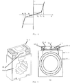
- Fig. 4
- ein Strom-Spannungs-Diagramm einer Suppressordiode,
- Fig. 5a
- eine perspektivische Darstellung eines Stromwandlers, und
- Fig. 5a
- eine Schnittdarstellung des Stromwandlers.
- Die
Fig. 1 zeigt ein erstes Ausführungsbeispiel der erfindungsgemäßen Schutzschaltung 12 für einen Stromwandler 10. Die Schutzschaltung 12 dient zum Verhindern, dass eine Sekundärspannung Us an einem Sekundärkreis 10.1 des Stromwandlers 10 einen Sekundärspannungsschwellwert überschreitet. - Die Schutzschaltung 12 umfasst
- einen Schutzschaltungseingang 12.1, der an den Sekundärkreis 10.1 des Stromwandlers 10 gekoppelt ist, so dass die Sekundärspannung Us an dem Schutzschaltungseingang 12.1 anliegt,
- eine mit dem Schutzschaltungseingang 12.1 verbundene Steuereinheit 16, und
- eine mit dem Schutzschaltungseingang 12.1 verbundene Schaltereinheit 18, die mit der Steuereinheit 16 ansteuerbar verbunden ist.
- Die Steuereinheit 16 ist dazu ausgebildet, unter Ansprechen auf ein Überschreiten des Sekundärspannungsschwellwerts durch die Sekundärspannung Us, ein Steuersignal an die Schaltereinheit 18 bereitzustellen.
- Die Schaltereinheit 18 ist dazu ausgebildet, unter Ansprechen auf das von der Steuereinheit 16 bereitgestellte Steuersignal, den Schutzschaltungseingang 12.1 kurzzuschließen.
- In der
Fig. 1 ist ferner ein Strommessgerät 20, das zum Messen des Stroms durch den Sekundärkreis 10.1 ausgebildet ist. Während des Messbetriebs ist das Auftreten einer Überspannung am Sekundärkreis 10.1 sehr unwahrscheinlich. Die Wahrscheinlichkeit für das Auftreten einer Überspannung oder überhöhten Sekundärspannung Us erhöht sich aber substantiell, sobald das Strommessgerät 20 vom Sekundärkreis 10.1 abgeklemmt wird, was in derFig. 1 angedeutet ist. - Im Folgenden wird die Funktion der Schutzschaltung 12 erläutert.
- Beim Auftreten einer überhöhten Sekundärspannung Us am Sekundärkreis 10.1 liegt an der Steuereinheit 16 eine Spannung an, welche einen voreingestellten Sekundärspannungsschwellwert überschreitet. Unter Ansprechen auf diese Überschreitung stellt die Steuereinheit 16 ein Steuersignal an die Schaltereinheit 18 bereit, welches beispielsweise von LOW auf HIGH wechselt. Unter Ansprechen auf das Steuersignal reduziert die Schalteinheit 18 ihren Innenwiderstand auf annähernd Null und schließt damit den Sekundärkreis 10.1 kurz.
- Die
Fig. 2 zeigt ein zweites Ausführungsbeispiel der erfindungsgemäßen Schutzschaltung 12 für einen Stromwandler 10. Im Unterschied zum ersten Ausführungsbeispiel umfasst die Schutzschaltung 12 gemäß dem inFig. 2 gezeigten Ausführungsbeispiel eine Begrenzungseinheit 14, die parallel zur Steuereinheit 16 und zur Schaltereinheit 18 geschaltet ist und mit dem Sekundärkreis 10.1 verbunden ist. - Vorteilhafter Weise ergänzen und unterstützen sich Begrenzungseinheit 14, Schaltereinheit 18 und Steuereinheit 16 gegenseitig bezüglich der Schutzfunktion für den Stromwandler 12. Einerseits, weil die Schaltereinheit 18 für größere Ströme als die Begrenzungseinheit 14 ausgelegt ist. Gemeinsam können die Komponenten Schaltereinheit 18 und Begrenzungseinheit 14 einen größeren Strom ertragen als jede Komponente für sich allein.
- Auf der anderen Seite unterstützt die Begrenzungseinheit 14 die Steuereinheit 16, weil mittels der Parallelschaltung von Begrenzungseinheit 14 und Steuereinheit 16 eine definierte Spannung an den Eingang der Steuereinheit 16 bereitgestellt wird.
- Bekanntlich haben Suppressordioden, die bevorzugt für die Begrenzungseinheit 14 verwendet wird, nach Erreichen der Durchbruchspannung (siehe
Fig. 4 ) noch einen endlichen Innenwiderstand, so dass sie nur Dauerströme führen können, die niedriger als die üblichen sekundären Nennströme von Wandlern sind. Dies ist ein möglicher Grund dafür, dass bisher keine Schutzschaltungen bekannt sind, die allein aus Suppressordioden bestehen. - Die zum Kurzschließen der Schaltereinheit 18 benötigte kurze Zeit stellt eine vernachlässigbar kleine Trägheit der Schutzschaltung 12 sicher, da die Steuereinheit 16 jede Halbwelle der Spannung am Sekundärkreis 10.1 "abtasten" kann. Sobald also die Spannung wieder unter einen vorgegebenen Grenzwert gesunken ist, wird in kürzester Zeit selbsttätig der durch die Schutzschaltung 12 hervorgerufene sekundärseitige Kurzschluss aufgehoben. Die Ansteuerung erfolgt periodisch.
- Die
Fig. 3 zeigt Details der inFig. 2 dargestellten Ausführungsform der Schutzschaltung 12. Demnach umfasst die Steuereinheit 16 einen Gleichrichter 16.1 und eine Komparatoreinheit 16.2. Die Komparatoreinheit 16.2 umfasst: - einen Komparator K mit einem positiven Eingang, einem negativen Eingang an welchem eine Spannung in Höhe von etwa der Eingangsspannung der Komparatoreinheit 16.2 anliegt, und einem Ausgang, welcher das Steuersignal bereitstellt;
- einen Spannungsteiler R2, R3, wobei der positive Eingang mit der Eingangsspannung der Komparatoreinheit 16.2 über den Spannungsteiler R2, R3 verbunden ist;
- eine Zener-Diode D2, die mit dem negativen Eingang verbunden ist, zum Begrenzen einer am negativen Eingang anliegenden Spannung;
- einen Kondensator C, der mit dem positiven Eingang verbunden ist.
- Die Begrenzungseinheit 14 umfasst eine Suppressordiode D1. Eine Strom-Spannungs-Kennlinie der Suppressordiode D1 ist in
Fig. 4 schematisch dargestellt. Hierin ist ersichtlich, dass die Suppressordiode D1 bidirektional im Rückwärtsbetrieb arbeitet. Die Durchlasskennlinie spielt hierbei keine Rolle. Markante Punkte der Kennlinie sind: - UR äußerster Punkt der Sperrspannung (revers-stand-off voltage),
- UB Durchbruchspannung (break-down voltage),
- UC Begrenzungsspannung (clamping voltage).
- Die Schaltereinheit 18 umfasst zwei in einer Back-to-Back Schaltung angeordnete MOSFETs T1, T2. Hierbei sind die Drain-Anschlüsse der Transistoren T1, T2 jeweils mit den Klemmen des Schutzschaltungseingangs verbunden, und die Gates sind mit dem Komparator K der Komparatoreinheit 16.2 zum Zuführen des Steuersignals verbunden.
- Hierbei wird vorteilhafter Weise ein Kurzschluss automatisch mit den kleinen und leichten Halbleitern der zwei N-Kanal FETs hergestellt, die in der Back-to-Back Schaltung angeordnet sind.
- Die beiden Transistoren T1, T2 schließen den Wechselstrom durch den Sekundärkreis 10.1 nahezu leistungsfrei kurz. Damit ist es möglich auch sehr hohe Ströme, wie beispielsweise einen thermischen Bemessungs-Kurzzeitstrom, welcher das 60-fache des Nennstroms von 5A, also 300 A, beträgt, für eine Sekunde abzuleiten und einen Bemessungs-Stoßstrom welcher das 2,5-fache des Bemessungs-Kurzzeitstroms, also 750 A, beträgt, für eine Halbwelle abzuleiten.
- Der Kurzschluss wird ausgeführt, bevor die Spannung einen gefährlichen Wert überschreitet. Ein solcher Wert entspricht einem Quotienten von Bemessungsleistung und sekundärem Bemessungsstrom des Messwandlers.
- Gemäß
Fig. 3 wird die gleichgerichtete Spannung Ug durch den Komparator K, mit der Spannung an einer Zener-Diode D2 verglichen. Der Strom durch den Gleichrichter 22 lädt den Kondensator C auf, der die notwendige Spannung für den Komparator K und die Ansteuerung der Transistoren T1, T2 bereitstellt. - Sobald die Spannung am Eingang des Komparators K die Schwellspannung des Komparators K erreicht, wird der Sekundärkreis 10.1 kurzgeschlossen und der Kondensator C entlädt sich über R1, R2, R3, D1 und K, bis die Abschaltspannung am positiven Eingang des Komparators K wieder erreicht ist.
- Wenn beispielsweise R4 sehr groß ist und zugleich R2, R3 gleich groß sind, dann ergibt sich ein Sekundärspannungsschwellwert in doppelter Höhe der Zener-Spannung. Die Parameter der Bauelemente der Steuereinheit 16, vorzugsweise die Parameter von R1, R2, R3, D1 und K, ermöglichen somit eine Festlegung des Sekundärspannungsschwellwerts, insbesondere im Verhältnis zur Sekundärspannung Us.
- Die Betriebsspannung des Komparators K ist durch die Gleichrichterdioden vom Kurzschluss getrennt. Steht nach dem Entfernen des Kurzschlusses weiterhin eine zu hohe Spannung am Sekundärkreis 10.1 an, wird der Vorgang wiederholt, sodass die Einschaltspannung am positiven Eingang des Komparators K niemals überschritten werden kann.
- Die Einschaltspannung und Ausschaltspannung am positiven Eingang des Komparators K sind über R4 durch eine Hysterese der Komparatoreinheit 16.2 getrennt, sodass keine undefinierten Schwingungen entstehen können. Die Schaltschwellen werden durch die Zener-Diode D2 und die eingestellte Hysterese bestimmt. Das Verhältnis der Widerstände R2, R3 zu dem Kondensator C bestimmt die Häufigkeit des Schaltvorganges.
- Diese Schutzschaltung 12 kann in den Kopf des Stromwandlers 10 untergebracht werden und fest mit der Sekundärkreis 10.1 verbunden werden. Somit funktioniert der automatische Kurzschluss immer, unabhängig davon, wo der Sekundärkreis 10.1 unterbrochen wird.
- Bei der Unterbringung der Schutzschaltung 12 beispielsweise in einem Schaltschrank, welcher die Komponenten einer Anlage beherbergt, an welche der Stromwandler 10 für eine Strommessung angeordnet ist, kann ein Verbindungskabel zur Schutzschaltung 12 an beliebiger Stelle zwischen Stromwandler 10 und Messgerät 20 unterbrochen werden, direkt oder unmittelbar an den Anschlüssen des Stromwandlers 10 oder des Messgerätes 20.
- Die Schutzschaltung 12 kann auch nach Fertigstellung des Stromwandlers 10 in den Sekundärstromkreis eingefügt werden. Das heißt, ein Nachrüsten des Stromwandlers 10 mit der Schutzschaltung 12 ist möglich.
- Eine Möglichkeit zur Verringerung der Kosten und Baugröße besteht darin, den Maximalstrom des Sekundärkreises 10.1 durch Variation des Materials des Stromwandlers 10 zu begrenzen. Durch angepasstes Kernmaterial kann der magnetische Fluss begrenzt werden, wodurch auch der Strom im Sekundärkreis 10.1 begrenzt wird.
- Die
Fig. 5a, 5b zeigen zwei Ansichten eines Stromwandlergehäuses 10.2, das einen Stromwandler 10 beherbergt. Das Stromwandlergehäuse 10.2 umfasst - ein Sekundärkreisgehäuse 10.5, in welchem der Sekundärkreis 10.1 des Stromwandlers 10 untergebracht ist, und
- ein Sekundärklemmengehäuse 10.3, genannt auch "Sekundärklemmenkasten", in welchem Sekundärklemmen untergebracht sind, an denen die Sekundärspannung Us abgegriffen werden kann.
- Die Schutzschaltung 12 ist in dem Stromwandlergehäuse 10.2, vorzugsweise im Sekundärklemmenkasten 10.3, untergebracht oder angeordnet. Die Schutzschaltung 12 ist direkt oder unmittelbar bei den Sekundärklemmen des Sekundärkreises 10.1 angeordnet. Die Schutzschaltung ist damit in dem Gehäuse 10.2 des Stromwandlers 10 vollständig integriert.
-
- 10
- Stromwandler
- 10.1
- Sekundärkreis des Stromwandlers
- 10.2
- Stromwandlergehäuse
- 10.3
- Sekundärklemmenkasten, Sekundärklemmengehäuse
- 10.4
- Sekundärkreisklemmen
- 10.5
- Sekundärkreisgehäuse
- 12
- Schutzschaltung
- 12.1
- Schutzschaltungseingang
- 14
- Begrenzungseinheit
- 16
- Steuereinheit
- 16.1
- Gleichrichter
- 16.2
- Komparatoreinheit
- 18
- Schaltereinheit
- 20
- Strommessgerät, Shunt-Widerstand
- D1
- Suppressordiode
- D2
- Zenerdiode
- K
- Komparator
- R1-R4
- Widerstände
- T1,T2
- Transistoren
- Ug
- Gleichspannung
- Us
- Sekundärspannung
Claims (7)
- Schutzschaltung für einen Stromwandler (10) zum Verhindern, dass eine Sekundärspannung (Us) an einem Sekundärkreis (10.1) des Stromwandlers (10) einen Sekundärspannungsschwellwert überschreitet, umfassend- einen Schutzschaltungseingang (12.1), der an den Sekundärkreis (10.1) des Stromwandlers (10) koppelbar ist, so dass die Sekundärspannung (Us) an dem Schutzschaltungseingang (12.1) anliegt,- eine mit dem Schutzschaltungseingang (12.1) verbundene Steuereinheit (16), und- eine mit dem Schutzschaltungseingang (12.1) verbundene Schaltereinheit (18), die mit der Steuereinheit (16) ansteuerbar verbunden ist,wobei- die Steuereinheit (16) eine Komparatoreinheit (16.2) umfasst und dazu ausgebildet ist, unter Ansprechen auf ein Überschreiten des Sekundärspannungsschwellwerts durch die Sekundärspannung (Us), ein Steuersignal an die Schaltereinheit (18) bereitzustellen, falls eine Eingangsspannung der Komparatoreinheit (16.2) einen Schwellwert überschreitet,- die Steuereinheit (16) ferner einen mit dem Schutzschaltungseingang (12.1) verbundenen Gleichrichter (16.1) zum Bereitstellen einer von einer Amplitude der Sekundärspannung (Us) abhängigen Gleichspannung (Ug) als Eingangsspannung der Komparatoreinheit (16.2) umfasst,- die Schaltereinheit (18) als eine Halbleiterschaltung ausgebildet ist, die zwei in einer Back-to-Back Schaltung anti-seriell angeordnete MOSFETs (T1, T2) umfasst, welche an einem Mittelanschluss miteinander verbunden sind,- der Gleichrichter (16.1) vier Brückenzweige umfasst, wobei zwei Brückenzweige die Gleichspannung (Ug) bereitstellen und zwei Brückenzweige mit dem Mittelanschluss der Schaltereinheit verbunden sind, und- die Schaltereinheit (18) dazu ausgebildet ist, unter Ansprechen auf das von der Steuereinheit (16) bereitgestellte Steuersignal, den Schutzschaltungseingang (12.1) kurzzuschließen.
- Schutzschaltung nach Anspruch 1, gekennzeichnet durch mindestens eines der folgenden Merkmale:- die Steuereinheit (16) ist direkt oder unmittelbar mit dem Schutzschaltungseingang (12.1) verbunden;- die Schaltereinheit (18) ist direkt oder unmittelbar mit dem Schutzschaltungseingang (12.1) verbunden;- die Schutzschaltung (12) umfasst eine mit dem Schutzschaltungseingang (12.1) verbundene Begrenzungseinheit (14) für einen Überspannungsschutz.
- Schutzschaltung nach einem der vorhergehenden Ansprüche, dadurch gekennzeichnet, dass die Komparatoreinheit (16.2) eine oder mehrere der folgenden Komponenten umfasst:- einen Komparator (K) mit einem positiven Eingang, einem negativen Eingang an welchem eine Spannung in Höhe von etwa der Eingangsspannung der Komparatoreinheit (16.2) anliegt, und einem Ausgang, welcher das Steuersignal bereitstellt;- einen Spannungsteiler (R2, R3), wobei der positive Eingang mit der Eingangsspannung der Komparatoreinheit (16.2) über den Spannungsteiler (R2, R3) verbunden ist;- eine Zener-Diode (D2), die mit dem negativen Eingang verbunden ist, zum Begrenzen einer am negativen Eingang anliegenden Spannung;- einen Kondensator (C), der mit dem positiven Eingang verbunden ist.
- Schutzschaltung nach einem der vorhergehenden Ansprüche, dadurch gekennzeichnet, dass die Schaltereinheit (18) einen Optokoppler zum Einkoppeln des Steuersignals umfasst.
- Schutzschaltung nach einem der vorhergehenden Ansprüche, dadurch gekennzeichnet, dass die Begrenzungseinheit (14) eine oder mehrere der folgenden Komponenten umfasst:- eine Suppressordiode (D1);- einen Varistor;- einen Gasableiter.
- Stromwandler mit einer Schutzschaltung (12) nach einem der vorhergehenden Ansprüche.
- Stromwandler nach dem vorhergehenden Anspruch, dadurch gekennzeichnet, dass die Schutzschaltung (12) im Gehäuse (10.2), insbesondere im Sekundärklemmenkasten (10.3) des Stromwandlers (10) beherbergt ist.
Applications Claiming Priority (2)
| Application Number | Priority Date | Filing Date | Title |
|---|---|---|---|
| DE102012111061.1A DE102012111061A1 (de) | 2012-11-16 | 2012-11-16 | Schutzschaltung für einen Stromwandler und Stromwandler mit einer Schutzschaltung |
| PCT/EP2013/073305 WO2014075989A1 (de) | 2012-11-16 | 2013-11-07 | Schutzschaltung für einen stromwandler und stromwandler mit einer schutzschaltung |
Publications (2)
| Publication Number | Publication Date |
|---|---|
| EP2920857A1 EP2920857A1 (de) | 2015-09-23 |
| EP2920857B1 true EP2920857B1 (de) | 2021-07-28 |
Family
ID=49554252
Family Applications (1)
| Application Number | Title | Priority Date | Filing Date |
|---|---|---|---|
| EP13789278.2A Active EP2920857B1 (de) | 2012-11-16 | 2013-11-07 | Schutzschaltung für einen stromwandler und stromwandler mit einer schutzschaltung |
Country Status (5)
| Country | Link |
|---|---|
| US (1) | US10498138B2 (de) |
| EP (1) | EP2920857B1 (de) |
| CN (2) | CN105191043A (de) |
| DE (1) | DE102012111061A1 (de) |
| WO (1) | WO2014075989A1 (de) |
Families Citing this family (15)
| Publication number | Priority date | Publication date | Assignee | Title |
|---|---|---|---|---|
| DE102014105888A1 (de) * | 2014-04-25 | 2015-10-29 | Phoenix Contact Gmbh & Co. Kg | Andockmodul für einen Stromwandler und Stromwandler mit einem Andockmodul |
| US9489026B2 (en) * | 2014-11-13 | 2016-11-08 | Electronic Systems Protection, Inc. | Selective event reaction processing in power control |
| US10014680B2 (en) * | 2014-12-09 | 2018-07-03 | Electronic Systems Protection, Inc. | Overvoltage notching of electricity delivered to an electrical load |
| WO2016125028A2 (en) * | 2015-02-03 | 2016-08-11 | Abb Technology Ltd. | System for monitoring electrical power transmission line |
| DE102015103296B4 (de) * | 2015-03-06 | 2022-06-09 | Phoenix Contact Gmbh & Co. Kg | Messvorrichtung zum Bereitstellen eines normierten elektrischen Ausgangssignals und elektronischer Messumformer |
| DE102015115410A1 (de) * | 2015-09-11 | 2017-03-16 | Phoenix Contact Gmbh & Co. Kg | Induktive Strommesswandlervorrichtung |
| FR3047084B1 (fr) * | 2016-01-22 | 2018-02-16 | Safran Electrical & Power | Dispositif de mesure du courant protege contre les surtensions en cas d'ouverture du circuit |
| DE102017109378B4 (de) * | 2017-02-16 | 2022-07-07 | Dehn Se | Elektronische Sicherung für eine, an ein Niedervolt-Gleichspannungsnetz anschließbare Last zum Schutz vor transienten und temporären Überspannungen |
| IL264042B (en) | 2018-12-31 | 2020-07-30 | Doron Eyal | Systems and methods for regulating force withdrawal from inspiratory force |
| CN111537907A (zh) | 2020-05-15 | 2020-08-14 | 北京小米移动软件有限公司 | 电源通断检测电路、方法、装置及存储介质 |
| CN112129985B (zh) * | 2020-09-09 | 2023-12-22 | 贵州电网有限责任公司 | 一种钳式互感器智能控制装置 |
| CN113064062A (zh) * | 2021-03-26 | 2021-07-02 | 广东电网有限责任公司 | 断路器二次回路的监测电路和装置 |
| GB2614280A (en) * | 2021-12-23 | 2023-07-05 | Synaptec Ltd | Signal conditioning stage |
| EP4213327A1 (de) * | 2022-01-14 | 2023-07-19 | ADB Safegate BV | Spannungsbegrenzungsvorrichtung für konstantstromkreise |
| WO2023140868A1 (en) * | 2022-01-24 | 2023-07-27 | Micro Motion, Inc. | Timer-based fault protection circuit |
Citations (5)
| Publication number | Priority date | Publication date | Assignee | Title |
|---|---|---|---|---|
| US3030524A (en) * | 1958-12-17 | 1962-04-17 | Bell Telephone Labor Inc | Balanced transistor swiching circuits |
| US5103154A (en) * | 1990-05-25 | 1992-04-07 | Texas Instruments Incorporated | Start winding switch protection circuit |
| WO2004040761A1 (en) * | 2002-10-29 | 2004-05-13 | Koninklijke Philips Electronics N.V. | Bi-directional double nmos switch |
| DE102007008264A1 (de) * | 2007-02-20 | 2008-08-21 | Robert Bosch Gmbh | Schaltungsanordnung mit einem bidirektional sperrenden Halbleiterrelais |
| US20100270982A1 (en) * | 2009-04-24 | 2010-10-28 | Lutron Electronics Co., Inc. | Smart Electronic Switch for Low-Power Loads |
Family Cites Families (22)
| Publication number | Priority date | Publication date | Assignee | Title |
|---|---|---|---|---|
| BE559161A (de) | 1956-07-18 | |||
| CA1152556A (fr) * | 1981-03-03 | 1983-08-23 | Julien Simard | Protecteur de transformateur d'intensite |
| US4698740A (en) * | 1986-02-14 | 1987-10-06 | Westinghouse Electric Corp. | Current fed regulated voltage supply |
| FR2664760B1 (fr) * | 1990-07-13 | 1996-09-27 | Sgs Thomson Microelectronics | Dispositif de protection contre des surtensions et sa realisation monolithique. |
| US5488534A (en) * | 1993-08-19 | 1996-01-30 | Emerson Electric Co. | Transient voltage surge suppression module with ultrafast fusing |
| JPH08317561A (ja) * | 1995-05-22 | 1996-11-29 | Tokyo Electric Power Co Inc:The | 高調波抑制装置 |
| CA2183176C (en) * | 1995-08-18 | 2000-10-24 | Brian R. Pelly | High power dc blocking device for ac and fault current grounding |
| JPH10510139A (ja) * | 1995-09-25 | 1998-09-29 | フィリップス エレクトロニクス ネムローゼ フェンノートシャップ | 電源回路 |
| DE19641187C2 (de) * | 1996-09-24 | 1998-07-23 | Siemens Ag | Schaltungsanordnung zur Energieversorgung von elektronischen Auslöseeinrichtungen |
| FR2764136B1 (fr) * | 1997-05-28 | 1999-08-13 | Sgs Thomson Microelectronics | Protection contre des surtensions d'un transistor mos de puissance integre |
| CN1190876C (zh) * | 2000-07-18 | 2005-02-23 | 全汉企业股份有限公司 | 电源供应器的过电压保护电路 |
| EP1304786A1 (de) * | 2001-10-18 | 2003-04-23 | ABB Schweiz AG | Spannungsbegrenzer |
| US7102253B2 (en) * | 2001-12-31 | 2006-09-05 | Lewis James M | MOSFET based, high voltage, electronic relays for AC power switching and inductive loads |
| JP3656911B2 (ja) * | 2002-09-27 | 2005-06-08 | オリオン電機株式会社 | 電源回路 |
| CN201528192U (zh) * | 2009-10-23 | 2010-07-14 | 佛山市南海展晴玩具有限公司 | 霓虹灯电子变压器保护电路 |
| CN101854766B (zh) * | 2010-04-23 | 2013-03-27 | 清华大学 | 无极灯电源电路,及其保护方法和保护电路 |
| US8861164B2 (en) * | 2011-02-04 | 2014-10-14 | Fairchild Semiconductor Corporation | Integrated overdrive and overvoltage protection device |
| US20120243136A1 (en) | 2011-03-23 | 2012-09-27 | Satcon Technology Corporation | Surge protection arrangement for electrical circuits |
| US8929042B2 (en) * | 2011-03-30 | 2015-01-06 | Thomas & Betts International, Inc. | Surge protective device with contoller |
| US9066453B2 (en) * | 2012-03-06 | 2015-06-23 | Mission Motor Company | Power electronic system and method of assembly |
| CN102709901B (zh) * | 2012-06-14 | 2016-06-01 | 北京恒源利通电力技术有限公司 | 电流互感器过压保护方法和装置 |
| CN103683523B (zh) * | 2012-09-07 | 2018-04-13 | 捷通国际有限公司 | 用于双向无线功率传输的系统和方法 |
-
2012
- 2012-11-16 DE DE102012111061.1A patent/DE102012111061A1/de not_active Withdrawn
-
2013
- 2013-11-07 EP EP13789278.2A patent/EP2920857B1/de active Active
- 2013-11-07 CN CN201380065720.XA patent/CN105191043A/zh active Pending
- 2013-11-07 WO PCT/EP2013/073305 patent/WO2014075989A1/de active Application Filing
- 2013-11-07 CN CN202010741426.8A patent/CN111864712B/zh active Active
- 2013-11-07 US US14/442,886 patent/US10498138B2/en active Active
Patent Citations (5)
| Publication number | Priority date | Publication date | Assignee | Title |
|---|---|---|---|---|
| US3030524A (en) * | 1958-12-17 | 1962-04-17 | Bell Telephone Labor Inc | Balanced transistor swiching circuits |
| US5103154A (en) * | 1990-05-25 | 1992-04-07 | Texas Instruments Incorporated | Start winding switch protection circuit |
| WO2004040761A1 (en) * | 2002-10-29 | 2004-05-13 | Koninklijke Philips Electronics N.V. | Bi-directional double nmos switch |
| DE102007008264A1 (de) * | 2007-02-20 | 2008-08-21 | Robert Bosch Gmbh | Schaltungsanordnung mit einem bidirektional sperrenden Halbleiterrelais |
| US20100270982A1 (en) * | 2009-04-24 | 2010-10-28 | Lutron Electronics Co., Inc. | Smart Electronic Switch for Low-Power Loads |
Also Published As
| Publication number | Publication date |
|---|---|
| US20150333509A1 (en) | 2015-11-19 |
| WO2014075989A1 (de) | 2014-05-22 |
| DE102012111061A1 (de) | 2014-05-22 |
| EP2920857A1 (de) | 2015-09-23 |
| US10498138B2 (en) | 2019-12-03 |
| CN105191043A (zh) | 2015-12-23 |
| CN111864712B (zh) | 2023-07-14 |
| CN111864712A (zh) | 2020-10-30 |
Similar Documents
| Publication | Publication Date | Title |
|---|---|---|
| EP2920857B1 (de) | Schutzschaltung für einen stromwandler und stromwandler mit einer schutzschaltung | |
| DE102014105888A1 (de) | Andockmodul für einen Stromwandler und Stromwandler mit einem Andockmodul | |
| EP2418748B1 (de) | Energieversorgungsvorrichtung | |
| EP0890220B1 (de) | Elektronisches abzweigschaltgerät | |
| WO2011036287A1 (de) | Vorrichtung zum kurzschliessen | |
| DE3622293A1 (de) | Festkoerper-nebenschlussschaltkreis fuer leckstromleistungssteuerung | |
| DE102011011983A1 (de) | Fehlerstrom-Schutzeinrichtung | |
| BE1026372B1 (de) | Schutzvorrichtung | |
| WO2010046247A1 (de) | Schutzschaltung und messgerät mit einer solchen schutzschaltung | |
| EP1078432B1 (de) | Schutzschaltgerät | |
| DE3531023A1 (de) | Schaltungsanordnung zur erfassung eines fehler- bzw. differenzstromes | |
| EP2355287A1 (de) | Überstromschutzeinrichtung für Elektromotoren | |
| DE3814251C1 (en) | Protective circuit for capacitive loads | |
| DE3542765C2 (de) | Versorgungsschaltung | |
| DE102018112914B4 (de) | Elektrische Schutzvorrichtung für eine mechanische Anlage | |
| DE102018114129A1 (de) | Schutzvorrichtung | |
| EP3053270B1 (de) | Invertschaltung mit spannungsbegrenzung | |
| DE102012222782A1 (de) | Schaltvorrichtung mit Überspannungsschutz | |
| DE102018212950B4 (de) | Niederspannungsleistungsschalter und Verfahren | |
| DE102020206253B3 (de) | Überspannungsschutz | |
| DE102010061766A1 (de) | Schalter, insbesondere Leistungsschalter für Niederspannungen | |
| EP2394150A1 (de) | Halbleiter-temperatursensor mit esd-schutz | |
| DE60112321T2 (de) | Einer messschnittstelle zuordbare einrichtung zur unterdrückung von störungen | |
| WO2023011768A1 (de) | Trennschaltereinheit | |
| WO2008141595A1 (de) | Schutzbeschaltung |
Legal Events
| Date | Code | Title | Description |
|---|---|---|---|
| PUAI | Public reference made under article 153(3) epc to a published international application that has entered the european phase |
Free format text: ORIGINAL CODE: 0009012 |
|
| 17P | Request for examination filed |
Effective date: 20150414 |
|
| AK | Designated contracting states |
Kind code of ref document: A1 Designated state(s): AL AT BE BG CH CY CZ DE DK EE ES FI FR GB GR HR HU IE IS IT LI LT LU LV MC MK MT NL NO PL PT RO RS SE SI SK SM TR |
|
| AX | Request for extension of the european patent |
Extension state: BA ME |
|
| DAX | Request for extension of the european patent (deleted) | ||
| STAA | Information on the status of an ep patent application or granted ep patent |
Free format text: STATUS: EXAMINATION IS IN PROGRESS |
|
| 17Q | First examination report despatched |
Effective date: 20180801 |
|
| STAA | Information on the status of an ep patent application or granted ep patent |
Free format text: STATUS: EXAMINATION IS IN PROGRESS |
|
| REG | Reference to a national code |
Ref country code: DE Ref legal event code: R079 Ref document number: 502013015854 Country of ref document: DE Free format text: PREVIOUS MAIN CLASS: H02H0009040000 Ipc: H03K0017687000 |
|
| GRAP | Despatch of communication of intention to grant a patent |
Free format text: ORIGINAL CODE: EPIDOSNIGR1 |
|
| STAA | Information on the status of an ep patent application or granted ep patent |
Free format text: STATUS: GRANT OF PATENT IS INTENDED |
|
| RIC1 | Information provided on ipc code assigned before grant |
Ipc: H03K 17/687 20060101AFI20210325BHEP Ipc: H02H 9/04 20060101ALI20210325BHEP Ipc: H01F 27/40 20060101ALI20210325BHEP Ipc: G01R 1/36 20060101ALI20210325BHEP Ipc: G01R 15/18 20060101ALI20210325BHEP Ipc: H01F 38/32 20060101ALI20210325BHEP Ipc: H02H 7/04 20060101ALI20210325BHEP Ipc: H03K 17/082 20060101ALI20210325BHEP |
|
| INTG | Intention to grant announced |
Effective date: 20210420 |
|
| GRAS | Grant fee paid |
Free format text: ORIGINAL CODE: EPIDOSNIGR3 |
|
| GRAA | (expected) grant |
Free format text: ORIGINAL CODE: 0009210 |
|
| STAA | Information on the status of an ep patent application or granted ep patent |
Free format text: STATUS: THE PATENT HAS BEEN GRANTED |
|
| AK | Designated contracting states |
Kind code of ref document: B1 Designated state(s): AL AT BE BG CH CY CZ DE DK EE ES FI FR GB GR HR HU IE IS IT LI LT LU LV MC MK MT NL NO PL PT RO RS SE SI SK SM TR |
|
| REG | Reference to a national code |
Ref country code: GB Ref legal event code: FG4D Free format text: NOT ENGLISH |
|
| REG | Reference to a national code |
Ref country code: CH Ref legal event code: EP |
|
| REG | Reference to a national code |
Ref country code: DE Ref legal event code: R096 Ref document number: 502013015854 Country of ref document: DE |
|
| REG | Reference to a national code |
Ref country code: AT Ref legal event code: REF Ref document number: 1415639 Country of ref document: AT Kind code of ref document: T Effective date: 20210815 |
|
| REG | Reference to a national code |
Ref country code: IE Ref legal event code: FG4D Free format text: LANGUAGE OF EP DOCUMENT: GERMAN |
|
| REG | Reference to a national code |
Ref country code: LT Ref legal event code: MG9D |
|
| REG | Reference to a national code |
Ref country code: NL Ref legal event code: MP Effective date: 20210728 |
|
| PG25 | Lapsed in a contracting state [announced via postgrant information from national office to epo] |
Ref country code: NO Free format text: LAPSE BECAUSE OF FAILURE TO SUBMIT A TRANSLATION OF THE DESCRIPTION OR TO PAY THE FEE WITHIN THE PRESCRIBED TIME-LIMIT Effective date: 20211028 Ref country code: PT Free format text: LAPSE BECAUSE OF FAILURE TO SUBMIT A TRANSLATION OF THE DESCRIPTION OR TO PAY THE FEE WITHIN THE PRESCRIBED TIME-LIMIT Effective date: 20211129 Ref country code: RS Free format text: LAPSE BECAUSE OF FAILURE TO SUBMIT A TRANSLATION OF THE DESCRIPTION OR TO PAY THE FEE WITHIN THE PRESCRIBED TIME-LIMIT Effective date: 20210728 Ref country code: NL Free format text: LAPSE BECAUSE OF FAILURE TO SUBMIT A TRANSLATION OF THE DESCRIPTION OR TO PAY THE FEE WITHIN THE PRESCRIBED TIME-LIMIT Effective date: 20210728 Ref country code: ES Free format text: LAPSE BECAUSE OF FAILURE TO SUBMIT A TRANSLATION OF THE DESCRIPTION OR TO PAY THE FEE WITHIN THE PRESCRIBED TIME-LIMIT Effective date: 20210728 Ref country code: FI Free format text: LAPSE BECAUSE OF FAILURE TO SUBMIT A TRANSLATION OF THE DESCRIPTION OR TO PAY THE FEE WITHIN THE PRESCRIBED TIME-LIMIT Effective date: 20210728 Ref country code: LT Free format text: LAPSE BECAUSE OF FAILURE TO SUBMIT A TRANSLATION OF THE DESCRIPTION OR TO PAY THE FEE WITHIN THE PRESCRIBED TIME-LIMIT Effective date: 20210728 Ref country code: BG Free format text: LAPSE BECAUSE OF FAILURE TO SUBMIT A TRANSLATION OF THE DESCRIPTION OR TO PAY THE FEE WITHIN THE PRESCRIBED TIME-LIMIT Effective date: 20211028 Ref country code: HR Free format text: LAPSE BECAUSE OF FAILURE TO SUBMIT A TRANSLATION OF THE DESCRIPTION OR TO PAY THE FEE WITHIN THE PRESCRIBED TIME-LIMIT Effective date: 20210728 Ref country code: SE Free format text: LAPSE BECAUSE OF FAILURE TO SUBMIT A TRANSLATION OF THE DESCRIPTION OR TO PAY THE FEE WITHIN THE PRESCRIBED TIME-LIMIT Effective date: 20210728 |
|
| PG25 | Lapsed in a contracting state [announced via postgrant information from national office to epo] |
Ref country code: PL Free format text: LAPSE BECAUSE OF FAILURE TO SUBMIT A TRANSLATION OF THE DESCRIPTION OR TO PAY THE FEE WITHIN THE PRESCRIBED TIME-LIMIT Effective date: 20210728 Ref country code: LV Free format text: LAPSE BECAUSE OF FAILURE TO SUBMIT A TRANSLATION OF THE DESCRIPTION OR TO PAY THE FEE WITHIN THE PRESCRIBED TIME-LIMIT Effective date: 20210728 Ref country code: GR Free format text: LAPSE BECAUSE OF FAILURE TO SUBMIT A TRANSLATION OF THE DESCRIPTION OR TO PAY THE FEE WITHIN THE PRESCRIBED TIME-LIMIT Effective date: 20211029 |
|
| PG25 | Lapsed in a contracting state [announced via postgrant information from national office to epo] |
Ref country code: DK Free format text: LAPSE BECAUSE OF FAILURE TO SUBMIT A TRANSLATION OF THE DESCRIPTION OR TO PAY THE FEE WITHIN THE PRESCRIBED TIME-LIMIT Effective date: 20210728 |
|
| REG | Reference to a national code |
Ref country code: DE Ref legal event code: R097 Ref document number: 502013015854 Country of ref document: DE |
|
| PG25 | Lapsed in a contracting state [announced via postgrant information from national office to epo] |
Ref country code: SM Free format text: LAPSE BECAUSE OF FAILURE TO SUBMIT A TRANSLATION OF THE DESCRIPTION OR TO PAY THE FEE WITHIN THE PRESCRIBED TIME-LIMIT Effective date: 20210728 Ref country code: SK Free format text: LAPSE BECAUSE OF FAILURE TO SUBMIT A TRANSLATION OF THE DESCRIPTION OR TO PAY THE FEE WITHIN THE PRESCRIBED TIME-LIMIT Effective date: 20210728 Ref country code: RO Free format text: LAPSE BECAUSE OF FAILURE TO SUBMIT A TRANSLATION OF THE DESCRIPTION OR TO PAY THE FEE WITHIN THE PRESCRIBED TIME-LIMIT Effective date: 20210728 Ref country code: EE Free format text: LAPSE BECAUSE OF FAILURE TO SUBMIT A TRANSLATION OF THE DESCRIPTION OR TO PAY THE FEE WITHIN THE PRESCRIBED TIME-LIMIT Effective date: 20210728 Ref country code: CZ Free format text: LAPSE BECAUSE OF FAILURE TO SUBMIT A TRANSLATION OF THE DESCRIPTION OR TO PAY THE FEE WITHIN THE PRESCRIBED TIME-LIMIT Effective date: 20210728 Ref country code: AL Free format text: LAPSE BECAUSE OF FAILURE TO SUBMIT A TRANSLATION OF THE DESCRIPTION OR TO PAY THE FEE WITHIN THE PRESCRIBED TIME-LIMIT Effective date: 20210728 |
|
| PLBE | No opposition filed within time limit |
Free format text: ORIGINAL CODE: 0009261 |
|
| STAA | Information on the status of an ep patent application or granted ep patent |
Free format text: STATUS: NO OPPOSITION FILED WITHIN TIME LIMIT |
|
| PG25 | Lapsed in a contracting state [announced via postgrant information from national office to epo] |
Ref country code: MC Free format text: LAPSE BECAUSE OF FAILURE TO SUBMIT A TRANSLATION OF THE DESCRIPTION OR TO PAY THE FEE WITHIN THE PRESCRIBED TIME-LIMIT Effective date: 20210728 |
|
| REG | Reference to a national code |
Ref country code: CH Ref legal event code: PL |
|
| 26N | No opposition filed |
Effective date: 20220429 |
|
| GBPC | Gb: european patent ceased through non-payment of renewal fee |
Effective date: 20211107 |
|
| PG25 | Lapsed in a contracting state [announced via postgrant information from national office to epo] |
Ref country code: LU Free format text: LAPSE BECAUSE OF NON-PAYMENT OF DUE FEES Effective date: 20211107 Ref country code: IT Free format text: LAPSE BECAUSE OF FAILURE TO SUBMIT A TRANSLATION OF THE DESCRIPTION OR TO PAY THE FEE WITHIN THE PRESCRIBED TIME-LIMIT Effective date: 20210728 Ref country code: BE Free format text: LAPSE BECAUSE OF NON-PAYMENT OF DUE FEES Effective date: 20211130 |
|
| REG | Reference to a national code |
Ref country code: BE Ref legal event code: MM Effective date: 20211130 |
|
| PG25 | Lapsed in a contracting state [announced via postgrant information from national office to epo] |
Ref country code: LI Free format text: LAPSE BECAUSE OF NON-PAYMENT OF DUE FEES Effective date: 20211130 Ref country code: CH Free format text: LAPSE BECAUSE OF NON-PAYMENT OF DUE FEES Effective date: 20211130 |
|
| PG25 | Lapsed in a contracting state [announced via postgrant information from national office to epo] |
Ref country code: IE Free format text: LAPSE BECAUSE OF NON-PAYMENT OF DUE FEES Effective date: 20211107 Ref country code: GB Free format text: LAPSE BECAUSE OF NON-PAYMENT OF DUE FEES Effective date: 20211107 |
|
| PG25 | Lapsed in a contracting state [announced via postgrant information from national office to epo] |
Ref country code: FR Free format text: LAPSE BECAUSE OF NON-PAYMENT OF DUE FEES Effective date: 20211130 |
|
| REG | Reference to a national code |
Ref country code: AT Ref legal event code: MM01 Ref document number: 1415639 Country of ref document: AT Kind code of ref document: T Effective date: 20211107 |
|
| PG25 | Lapsed in a contracting state [announced via postgrant information from national office to epo] |
Ref country code: AT Free format text: LAPSE BECAUSE OF NON-PAYMENT OF DUE FEES Effective date: 20211107 |
|
| PG25 | Lapsed in a contracting state [announced via postgrant information from national office to epo] |
Ref country code: HU Free format text: LAPSE BECAUSE OF FAILURE TO SUBMIT A TRANSLATION OF THE DESCRIPTION OR TO PAY THE FEE WITHIN THE PRESCRIBED TIME-LIMIT; INVALID AB INITIO Effective date: 20131107 |
|
| PGFP | Annual fee paid to national office [announced via postgrant information from national office to epo] |
Ref country code: DE Payment date: 20230127 Year of fee payment: 10 |
|
| P01 | Opt-out of the competence of the unified patent court (upc) registered |
Effective date: 20230424 |
|
| PG25 | Lapsed in a contracting state [announced via postgrant information from national office to epo] |
Ref country code: CY Free format text: LAPSE BECAUSE OF FAILURE TO SUBMIT A TRANSLATION OF THE DESCRIPTION OR TO PAY THE FEE WITHIN THE PRESCRIBED TIME-LIMIT Effective date: 20210728 |
|
| PG25 | Lapsed in a contracting state [announced via postgrant information from national office to epo] |
Ref country code: MK Free format text: LAPSE BECAUSE OF FAILURE TO SUBMIT A TRANSLATION OF THE DESCRIPTION OR TO PAY THE FEE WITHIN THE PRESCRIBED TIME-LIMIT Effective date: 20210728 |
|
| PGFP | Annual fee paid to national office [announced via postgrant information from national office to epo] |
Ref country code: DE Payment date: 20240129 Year of fee payment: 11 |