EP2920504B1 - Magnet zur magnetischen befestigung von leuchten; beleuchtungsvorrichtung und metallregal - Google Patents
Magnet zur magnetischen befestigung von leuchten; beleuchtungsvorrichtung und metallregal Download PDFInfo
- Publication number
- EP2920504B1 EP2920504B1 EP13792339.7A EP13792339A EP2920504B1 EP 2920504 B1 EP2920504 B1 EP 2920504B1 EP 13792339 A EP13792339 A EP 13792339A EP 2920504 B1 EP2920504 B1 EP 2920504B1
- Authority
- EP
- European Patent Office
- Prior art keywords
- magnet
- lamp
- illumination device
- shelves
- shelf
- Prior art date
- Legal status (The legal status is an assumption and is not a legal conclusion. Google has not performed a legal analysis and makes no representation as to the accuracy of the status listed.)
- Active
Links
- 239000002184 metal Substances 0.000 title claims description 24
- 238000005286 illumination Methods 0.000 title claims description 18
- 239000000853 adhesive Substances 0.000 claims description 7
- 230000001070 adhesive effect Effects 0.000 claims description 7
- 230000003760 hair shine Effects 0.000 description 4
- 238000005452 bending Methods 0.000 description 1
- 239000003795 chemical substances by application Substances 0.000 description 1
- 230000001419 dependent effect Effects 0.000 description 1
- 238000011161 development Methods 0.000 description 1
- 230000018109 developmental process Effects 0.000 description 1
- 238000004519 manufacturing process Methods 0.000 description 1
- 230000006641 stabilisation Effects 0.000 description 1
- 238000011105 stabilization Methods 0.000 description 1
Images

Classifications
-
- A—HUMAN NECESSITIES
- A47—FURNITURE; DOMESTIC ARTICLES OR APPLIANCES; COFFEE MILLS; SPICE MILLS; SUCTION CLEANERS IN GENERAL
- A47F—SPECIAL FURNITURE, FITTINGS, OR ACCESSORIES FOR SHOPS, STOREHOUSES, BARS, RESTAURANTS OR THE LIKE; PAYING COUNTERS
- A47F3/00—Show cases or show cabinets
- A47F3/001—Devices for lighting, humidifying, heating, ventilation
-
- F—MECHANICAL ENGINEERING; LIGHTING; HEATING; WEAPONS; BLASTING
- F21—LIGHTING
- F21S—NON-PORTABLE LIGHTING DEVICES; SYSTEMS THEREOF; VEHICLE LIGHTING DEVICES SPECIALLY ADAPTED FOR VEHICLE EXTERIORS
- F21S4/00—Lighting devices or systems using a string or strip of light sources
- F21S4/20—Lighting devices or systems using a string or strip of light sources with light sources held by or within elongate supports
- F21S4/28—Lighting devices or systems using a string or strip of light sources with light sources held by or within elongate supports rigid, e.g. LED bars
-
- F—MECHANICAL ENGINEERING; LIGHTING; HEATING; WEAPONS; BLASTING
- F21—LIGHTING
- F21V—FUNCTIONAL FEATURES OR DETAILS OF LIGHTING DEVICES OR SYSTEMS THEREOF; STRUCTURAL COMBINATIONS OF LIGHTING DEVICES WITH OTHER ARTICLES, NOT OTHERWISE PROVIDED FOR
- F21V21/00—Supporting, suspending, or attaching arrangements for lighting devices; Hand grips
- F21V21/08—Devices for easy attachment to any desired place, e.g. clip, clamp, magnet
- F21V21/096—Magnetic devices
-
- F—MECHANICAL ENGINEERING; LIGHTING; HEATING; WEAPONS; BLASTING
- F21—LIGHTING
- F21V—FUNCTIONAL FEATURES OR DETAILS OF LIGHTING DEVICES OR SYSTEMS THEREOF; STRUCTURAL COMBINATIONS OF LIGHTING DEVICES WITH OTHER ARTICLES, NOT OTHERWISE PROVIDED FOR
- F21V33/00—Structural combinations of lighting devices with other articles, not otherwise provided for
- F21V33/0004—Personal or domestic articles
- F21V33/0012—Furniture
-
- F—MECHANICAL ENGINEERING; LIGHTING; HEATING; WEAPONS; BLASTING
- F21—LIGHTING
- F21W—INDEXING SCHEME ASSOCIATED WITH SUBCLASSES F21K, F21L, F21S and F21V, RELATING TO USES OR APPLICATIONS OF LIGHTING DEVICES OR SYSTEMS
- F21W2131/00—Use or application of lighting devices or systems not provided for in codes F21W2102/00-F21W2121/00
- F21W2131/40—Lighting for industrial, commercial, recreational or military use
- F21W2131/405—Lighting for industrial, commercial, recreational or military use for shop-windows or displays
-
- F—MECHANICAL ENGINEERING; LIGHTING; HEATING; WEAPONS; BLASTING
- F21—LIGHTING
- F21Y—INDEXING SCHEME ASSOCIATED WITH SUBCLASSES F21K, F21L, F21S and F21V, RELATING TO THE FORM OR THE KIND OF THE LIGHT SOURCES OR OF THE COLOUR OF THE LIGHT EMITTED
- F21Y2103/00—Elongate light sources, e.g. fluorescent tubes
Definitions
- the present invention relates to a lighting device comprising a luminaire and at least one magnet for magnetically attaching luminaires to shelves of metal shelves, fastening means permitting attachment of the magnet to the luminaires, and a metal shelf comprising at least one having such lighting device.
- Such metal shelves are rarely equipped by the manufacturer of the shelf with lighting devices that illuminate the arranged in the metal shelves products accordingly. Rather, in many supermarkets, a multitude of metal shelves already exist, and then later on, lighting fixtures are to be installed to illuminate the products accordingly. This should be done in the simplest possible way and without tools, and it is also desired that the metal shelf is not damaged or must be modified.
- a lighting device is formed in which one or more magnets or a magnetic tape attached to a lamp or attached and with the help of the magnet or the magnetic tape, the lamp is then magnetically attached to the metal shelf.
- the lighting device is arranged on the underside of a shelf of the metal shelf and the lamp illuminates the located under the lighting device on a further shelf items or products accordingly.
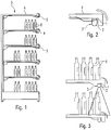
- FIG. 1 is a metal shelf 5 shown, in each case at the bottom of the shelves 4 lighting devices 3 are provided to illuminate the underlying products 6. Again FIG. 1 can be removed, it is provided that the lighting devices 3 are attached to the end of the shelves 4.
- FIG. 2 is then the end of a shelf 4 with a lighting device 3 shown enlarged.
- the lighting device 3 consists of a lamp 2 and a magnet 1, wherein the lamp 2 is magnetically held or fixed by means of the magnet 1 at the bottom and at the end of the shelf 4.
- the shelf 4 in this case has an angled edge, which obscures the lighting device 3 something.
- FIG. 3 is then shown by way of example the light output of the lighting device 3, wherein - like FIG. 3 it can be seen - the light is emitted substantially vertically downwards.
- the luminaire 2 of the illumination device 3 is a normal emitting illumination, for example a luminous rod, in which no special optics are provided for deflecting in a deviating direction.
- the magnets or the magnetic tape 1 are each made uniformly thick, whereby the lamp 2 is fixed vertically down to the bottom of the shelf. By this constant thickness of each magnet or the magnetic tape 1 thus results in a symmetrical attachment of the lamp 2 at the bottom of the shelf 4, whereby the in FIG. 3 shown light emission comes about.
- FIG. 4 shows a cylindrical round magnet 1, which is attached to the lamp 2.
- FIG. 5 magnetic tapes 1 are shown, which can be made different lengths depending on the desired length and then cut to length accordingly.
- FIG. 6 a rectangular shaped lamellar magnet 1 are taken, wherein in the FIG. 6a the lamellar configuration of the magnet can be seen and FIG. 6b the one in FIG. 6a surface shown opposite side shows.
- a possible means for fixing the lamp 2 be taken on the lamellar magnet 1, which is this latching or clamping means 7.
- Such locking or clamping means 7 for fixing the lamp 2 to the magnet 1 can also in the in FIG. 4 shown round magnet 1 or in the in FIG. 5 shown magnetic tapes 1 may be provided.
- the light is emitted by the attached to the magnets 1 to the shelves 4 lights 2 substantially vertically downwards.
- FIG. 3 shows that a portion of the emitted light is not directed to the products to be illuminated 6, but shines on the shelves 4 and thus leads to a lighting of lying in front of the metal shelf 5 area, which, for example, customers can be dazzled.
- this light shining beyond the shelves 4 is then absent during the lighting of the products 6, as a result of which not all products 6 standing on the shelves 4 may be adequately illuminated or a correspondingly larger-sized luminaire 2 is necessary.
- US 3,239,179 A shows a wall or ceiling hanger with a hook and a hook-carrying body, which can be fixed by means of screws, adhesive or magnet to the ceiling or wall.
- DE 20 2010 012629 U1 shows a light strip for furniture
- US 2011/038159 A1 shows magnetically mounted lamps
- US 2012/075857 A1 shows a magnetically mounted lamp
- DE 89 11 974 U1 shows a fortified example with magnets radiator.
- the present invention is accordingly the object of the in the FIGS. 1 to 3 To improve the product lighting shown in such a way that the efficiency of the product lighting is increased and energy can be saved.
- the object is achieved by a lighting device for illuminating arranged in or on metal shelves objects according to claim 1 and a metal shelf with a plurality of shelves according to claim 11.
- a lighting device for illuminating arranged in or on shelves of metal shelves objects which allow a lamp and at least one magnet for magnetic attachment of lights on shelves of metal shelves, the means for attachment, which allow attachment of the magnet to the lights, has, wherein the magnet is formed in a wedge shape in cross-section, wherein the magnet is fixed with the means for attachment to the lamp and wherein the magnet is provided for the magnetic attachment of the lamp to the shelves.
- a metal shelf with a plurality of shelves which has at least one such lighting device for illuminating arranged in or on the shelves objects, wherein the lighting device is arranged on the underside of a shelf and wherein the lamp by the wedge shape of the magnet asymmetrically at the bottom the shelf is magnetically fixed, such that the light output is substantially obliquely downward in the direction of the objects to be illuminated.
- the light is no longer symmetrically attached to the underside of a shelf, but rather asymmetrical, whereby the light output is no longer as usual vertically down but obliquely or inclined.
- the underside of a shelf By appropriate attachment to the underside of a shelf, it is thus achieved that substantially all of the light of the luminaire shines in the direction of the objects to be illuminated, thereby preventing, on the one hand, that light shines beyond the shelves and thus dazzles customers and, on the other hand the entire light emitted by the luminaire is used to illuminate the objects.
- the magnet is elongated, which may be a magnetic tape.
- the magnet could also be a round magnet designed in particular in the form of a cylinder, or a lamellar magnet, in particular a cuboid design.
- the attachment means may preferably be adhesive bonds or latching or clamping means.
- the luminaire is of elongated design, it being possible for this to be a luminous bar.
- the magnet may also be fixed to the luminaire such that the wedge-shaped cross section of the magnet is parallel to the cross section of the luminaire.
- FIGS. 1 to 3 a metal shelf with a product lighting from the prior art. It is provided that a lamp 2 is magnetically fixed by means of a uniformly thick magnet 1 to the underside of a shelf 4 of the metal shelf 5. Due to the uniform thickness of the magnet 1 results in a substantially vertically downwardly directed attachment of the lamp 2, whereby the light output of the lamp 2 is substantially vertically downwards and thus can be spoken of a symmetrical fastening in total.
- a magnet for magnetic attachment of the lamp 2 is now provided, which is wedge-shaped in cross section.
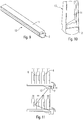
- FIGS. 7 and 8 By way of example, such a magnet 11 is shown, wherein the FIGS. 7 and 8 each only show different views.
- magnet 11 is an elongated wedge-shaped in cross-section magnet.
- the magnet 11 means for attachment, which allow attachment of the magnet 11 to the lamp 2, which in the FIGS. 7 and 8 are not shown.
- the agents may, for example, be adhesive bonds. Likewise, but could also locking and clamping means 7, as in FIG. 6b be shown provided.
- FIGS. 9 and 10 a lighting device 13 according to the invention is shown, which in the FIGS. 7 and 8 shown magnet 11 according to the invention and a lamp 2 has.
- the magnet 11 is fastened with the means for attachment to the lamp 2.
- FIGS. 9 and 10 can be removed, it is in the lamp 2 to an elongated luminescent rod, which is why the likewise elongated magnet 11 is necessarily attached to the lamp 2, that the wedge-shaped cross section of the elongate magnet 11 is parallel to the cross section of the lamp 2.
- the lighting device 13 is then as in FIG. 11 shown by the wedge shape of the magnet 11, the lamp 2 is no longer arranged vertically downwards but rather obliquely, such that the emitted light is also no longer directed vertically downwards but also oblique.
- the lighting device 13 is thereby arranged on the underside of the shelf 4, that the lamp 2 is inclined in the direction of the products to be illuminated. Due to the wedge-shaped configuration of the magnet 11 thus results in an asymmetric attachment of the lamp 2 at the bottom of the shelf 4, which, as from FIG. 11 shows, compared to FIG. 3 the light is directed substantially to the products 6 to be illuminated and no light is lost by shining on an area in front of the shelf 4.
- the configuration of the wedge shape of the magnet 11 accordingly determines the slope and thus the inclination angle of the lamp 2.
- a Changing the wedge shape also made a change in the angle of inclination.
- the magnet 11 is shown as an elongated magnetic tape, the design as a magnetic tape, which can be extruded in any form, allows a very inexpensive production.
- Magnet 11 shown an elongated groove which is provided for stabilization, in order to avoid excessive bending of the magnet 11. After attaching the magnet 11 to the lamp 2 by means of the attachment means this groove then plays only a minor role and reduces when using an adhesive bond as a means of attachment even the adhesive surface. Accordingly, the magnet 11 may be formed without a groove.
- the magnet according to the invention may also be a round magnet or lamellar magnet which is wedge-shaped in cross section, in which case two or more magnets are preferably provided along the illumination device in the case of an elongate illumination device. It should then be noted that the wedge-shaped cross section of all magnets is always aligned in the same direction to achieve the desired inclination.
- the wedge-shaped magnet allows the luminaire to be mounted obliquely and thus at a certain angle of inclination to the underside of a shelf, thereby ensuring that all the light from the luminaire is used for product lighting. As a result, an increase in the efficiency of the product lighting is achieved and, accordingly, an energy saving possible.
Landscapes
- Engineering & Computer Science (AREA)
- General Engineering & Computer Science (AREA)
- Health & Medical Sciences (AREA)
- Public Health (AREA)
- Arrangement Of Elements, Cooling, Sealing, Or The Like Of Lighting Devices (AREA)
- Non-Portable Lighting Devices Or Systems Thereof (AREA)
Description
- Die vorliegende Erfindung betrifft eine Beleuchtungsvorrichtung, die eine Leuchte und mindestens einen Magneten zur magnetischen Befestigung von Leuchten an Regalböden von Metallregalen, der Mittel zur Befestigung, die eine Befestigung des Magneten an den Leuchten ermöglichen, aufweist, aufweist, und ein Metallregal, das mindestens eine derartige Beleuchtungsvorrichtung aufweist.
- In Supermärkten kommen häufig Metallregale als sogenannte Trockenregale zum Einsatz, wobei diese sogenannten Trockenregale von beispielsweise Kühlregalen oder dergleichen zu unterscheiden sind.
- Derartige Metallregale sind dabei selten schon vom Hersteller des Regals mit Beleuchtungsvorrichtungen ausgestattet, die die in den Metallregalen angeordneten Produkte entsprechend beleuchten. In vielen Supermärkten ist es vielmehr so, dass eine Vielzahl von Metallregalen bereits vorhanden ist, und dann zu einem späteren Zeitpunkt nachträglich Beleuchtungsvorrichtungen angebracht werden sollen, um die Produkte entsprechend zu beleuchten. Dies sollte auf möglichst einfache Weise und ohne Werkzeuge erfolgen, wobei auch gewünscht ist, dass das Metallregal nicht beschädigt wird oder modifiziert werden muss.
- Aus dem Stand der Technik sind hierzu verschiedene Lösungen bekannt, wobei insbesondere bei Metallregalen der Einsatz von Magneten eine einfache und sinnvolle Lösung darstellt. Dabei ist vorgesehen, dass eine Beleuchtungsvorrichtung gebildet wird, bei der an einer Leuchte ein oder mehrere Magnete oder ein Magnetband angebracht bzw. befestigt werden und mit Hilfe der Magneten bzw. des Magnetbandes die Leuchte dann an dem Metallregal magnetisch befestigt wird.
- Im Einzelnen ist dabei dann vorgesehen, dass die Beleuchtungsvorrichtung an der Unterseite eines Regalbodens des Metallregals angeordnet ist und die Leuchte die unter der Beleuchtungsvorrichtung auf einem weiteren Regalboden befindlichen Gegenstände bzw. Produkte entsprechend beleuchtet. In
Figur 1 ist ein Metallregal 5 gezeigt, bei dem jeweils an der Unterseite der Regalböden 4 Beleuchtungsvorrichtungen 3 zur Beleuchtung der darunterliegenden Produkte 6 vorgesehen sind. Wie derFigur 1 entnommen werden kann, ist dabei vorgesehen, dass die Beleuchtungsvorrichtungen 3 am Ende der Regalböden 4 angebracht sind. - In
Figur 2 ist dann das Ende eines Regalbodens 4 mit einer Beleuchtungsvorrichtung 3 vergrößert dargestellt. Wie derFigur 2 zu entnehmen ist, besteht die Beleuchtungsvorrichtung 3 aus einer Leuchte 2 und einem Magnet 1, wobei die Leuchte 2 mit Hilfe des Magneten 1 an der Unterseite und am Ende des Regalbodens 4 magnetisch gehalten bzw. befestigt wird. Der Regalboden 4 weist hierbei eine abgewinkelte Kante auf, die die Beleuchtungsvorrichtung 3 etwas verdeckt. - In
Figur 3 wird dann beispielhaft die Lichtabgabe der Beleuchtungsvorrichtung 3 gezeigt, wobei - wieFigur 3 zu entnehmen ist - die Lichtabgabe im Wesentlichen senkrecht nach unten erfolgt. Dies ergibt sich im Wesentlichen daraus, dass es sich bei der Leuchte 2 der Beleuchtungsvorrichtung 3 um eine normal ausstrahlende Beleuchtung handelt, bspw. einen Leuchtstab, bei der keine speziellen Optiken zur Umlenkung in eine abweichende Richtung vorgesehen sind. Zusätzlich sind die Magnete bzw. das Magnetband 1 jeweils gleichmäßig dick ausgestaltet, wodurch die Leuchte 2 senkrecht nach unten an der Unterseite des Regalbodens befestigt ist. Durch diese gleichbleibende Dicke jedes Magneten bzw. des Magnetbandes 1 ergibt sich somit eine symmetrische Befestigung der Leuchte 2 an der Unterseite des Regalbodens 4, wodurch die inFigur 3 gezeigte Lichtabgabe zustande kommt. - Wie bereits zuvor angerührt, kann zur Befestigung der Leuchte 2 an dem Regalboden 4 entweder ein oder mehrere Magnete oder ein Magnetband 1 verwendet werden. In den
Figuren 4 bis 6 sind hierzu verschiedene Varianten dargestellt.Figur 4 zeigt dabei einen zylindrischen Rundmagnet 1, der an der Leuchte 2 befestigt ist. InFigur 5 sind Magnetbänder 1 dargestellt, die je nach gewünschter Länge unterschiedlich lang hergestellt und dann auch entsprechend abgelängt werden können. Demgegenüber kann derFigur 6 ein quaderförmig ausgestalteter Lamellenmagnet 1 entnommen werden, wobei in derFigur 6a die lamellenförmige Ausgestaltung des Magneten zu sehen ist undFigur 6b die der inFigur 6a dargestellten Oberfläche gegenüberliegende Seite zeigt. DerFigur 6b kann nun ein mögliches Mittel zur Befestigung der Leuchte 2 an dem Lamellenmagnet 1 entnommen werden, wobei es sich hierbei um Rast- bzw. Klemmmittel 7 handelt. Derartige Rast- bzw. Klemmmittel 7 zur Befestigung der Leuchte 2 an dem Magnet 1 können auch bei dem inFigur 4 gezeigten Rundmagnet 1 oder bei den inFigur 5 gezeigten Magnetbändern 1 vorgesehen sein. - Alternativ dazu können anstatt den Rast- bzw. Klemmmitteln 7 auch Klebeverbindungen als Mittel zur Befestigung an den Magneten 1 angebracht sein.
- Wie bereits zuvor angerührt, erfolgt die Lichtabgabe durch die mit dem Magneten 1 an die Regalböden 4 angebrachten Leuchten 2 im Wesentlichen senkrecht nach unten. Hierdurch ist, wie auch aus
Figur 3 hervorgeht, ein Teil des abgegebenen Lichts nicht auf die zu beleuchtenden Produkte 6 gerichtet, sondern scheint über die Regalböden 4 hinaus und führt dadurch zu einer Beleuchtung des vor dem Metallregal 5 liegenden Bereichs, wodurch bspw. Kunden geblendet werden können. Gleichzeitig fehlt dieses über die Regalböden 4 hinaus scheinende Licht dann bei der Beleuchtung der Produkte 6, wodurch möglicherweise nicht alle auf den Regalböden 4 stehende Produkte 6 ausreichend beleuchtet werden können bzw. eine entsprechend größer dimensionierte Leuchte 2 notwendig ist. -
US 3,239,179 A zeigt einen Wand- oder Deckenhänger mit einem Haken sowie einem den Haken tragenden Körper, welcher mittels Schrauben, Kleber oder Magneten an Decke oder Wand befestigt werden kann.DE 20 2010 012629 U1 zeigt eine Lichtleiste für Möbel,US 2011/038159 A1 zeigt magnetisch anzubringende Leuchtmittel,US 2012/075857 A1 zeigt eine magnetisch montierbare Leuchte undDE 89 11 974 U1 zeigt einen beispielsweise mit Magneten befestigbaren Strahler. - Der vorliegenden Erfindung liegt dementsprechend die Aufgabe zugrunde, die in den
Figuren 1 bis 3 gezeigte Produktbeleuchtung derart zu verbessern, dass die Effizienz der Produktbeleuchtung erhöht wird und Energie eingespart werden kann. - Die Aufgabe wird durch eine Beleuchtungsvorrichtung zur Beleuchtung von in bzw. auf Metallregalen angeordneten Gegenständen gemäß Anspruch 1 und einem Metallregal mit mehreren Regalböden gemäß Anspruch 11 gelöst. Vorteilhafte Weiterbildungen sind Gegenstand der abhängigen Ansprüche.
- Erfindungsgemäß wird eine Beleuchtungsvorrichtung zur Beleuchtung von in bzw. auf Regalböden von Metallregalen angeordneten Gegenständen vorgeschlagen, die eine Leuchte und mindestens einen Magnet zur magnetischen Befestigung von Leuchten an Regalböden von Metallregalen, der Mittel zur Befestigung, die eine Befestigung des Magneten an den Leuchten ermöglichen, aufweist, aufweist, wobei der Magnet im Querschnitt keilförmig ausgebildet ist, wobei der Magnet mit den Mitteln zur Befestigung an der Leuchte befestigt ist und wobei der Magnet zur magnetischen Befestigung der Leuchte an den Regalböden vorgesehen ist.
- Außerdem wird ein Metallregal mit mehreren Regalböden vorgeschlagen, welches mindestens eine derartige Beleuchtungsvorrichtung zur Beleuchtung von in bzw. auf den Regalböden angeordneten Gegenständen aufweist, wobei die Beleuchtungsvorrichtung an der Unterseite eines Regalbodens angeordnet ist und wobei die Leuchte durch die Keilform des Magneten asymmetrisch an der Unterseite des Regalbodens magnetisch befestigt ist, derart, dass die Lichtabgabe im Wesentlichen schräg nach unten in Richtung der zu beleuchtenden Gegenstände erfolgt.
- Durch die Keilform des Magneten wird somit erreicht, dass die Leuchte nicht mehr symmetrisch an der Unterseite eines Regalbodens befestigt ist sondern vielmehr asymmetrisch, wodurch die Lichtabgabe nicht mehr wie bisher senkrecht nach unten erfolgt sondern schräg bzw. geneigt. Durch entsprechende Anbringung an der Unterseite eines Regalbodens wird somit erreicht, dass im Wesentlichen das gesamte Licht der Leuchte in Richtung der zu beleuchtenden Gegenstände scheint, wodurch zum einen verhindert wird, dass Licht über die Regalböden hinaus scheint und somit Kunden blenden könnte und zum anderen wird das gesamte von der Leuchte abgegebene Licht zur Beleuchtung der Gegenstände verwendet. Hierdurch wird zum einen die Effizienz der gesamten Produktbeleuchtung gesteigert, da das gesamte abgegebene Licht auch tatsächlich Produkte beleuchtet und zum anderen ist es dann auch möglich entsprechend schwächere Leuchten zu verwenden, da kein Teil des von den Leuchten abgegebenen Lichts mehr verloren geht und somit keine überdimensionierten Leuchten mehr notwendig sind.
- Vorteilhafterweise kann vorgesehen sein, dass der Magnet länglich ausgestaltet ist, wobei es sich um ein Magnetband handeln kann. Alternativ könnte es sich bei dem Magneten aber auch um einen, insbesondere zylinderförmig ausgestalteten, Rundmagnet oder einen, insbesondere quaderförmig ausgestalteten, Lamellenmagnet handeln.
- Bei den Mitteln zur Befestigung kann es sich vorzugsweise um Klebeverbindungen oder um Rast- bzw. Klemmmittel handeln.
- Des Weiteren kann vorteilhafterweise auch vorgesehen sein, dass die Leuchte länglich ausgestaltet ist, wobei es sich hierbei um einen Leuchtstab handeln kann.
- Vorzugsweise kann der Magnet außerdem derart an der Leuchte befestigt sein, dass der keilförmige Querschnitt des Magnets parallel zu dem Querschnitt der Leuchte ist.
- Nachfolgend soll die Erfindung anhand von Ausführungsbeispielen und den beiliegenden Zeichnungen näher erläutert werden. Es zeigen:
- Figur 1
- Metallregal mit mehreren Beleuchtungsvorrichtungen zur Produktbeleuchtung entsprechend dem Stand der Technik;
- Figur 2
- vergrößerter Ausschnitt aus
Figur 1 mit einer Beleuchtungsvorrichtung; - Figur 3
- Darstellung der Lichtabstrahlrichtung der in
Figur 2 gezeigten Beleuchtungsvorrichtung; - Figur 4
- Leuchte mit einem Rundmagnet entsprechend dem Stand der Technik;
- Figur 5
- Magnetbänder entsprechend dem Stand der Technik;
- Figur 6
- Lamellenmagnet mit Mitteln zur Befestigung entsprechend dem Stand der Technik;
- Figur 7
- erfindungsgemäßer Magnet in einer ersten Ansicht;
- Figur 8
- erfindungsgemäßer Magnet in einer zweiten Ansicht;
- Figur 9
- erfindungsgemäße Beleuchtungsvorrichtung mit einem erfindungsgemäßen Magnet in einer ersten Ansicht;
- Figur 10
- erfindungsgemäße Beleuchtungsvorrichtung mit einem erfindungsgemäßen Magnet in einer zweiten Ansicht;
- Figur 11
- Darstellung der Lichtabstrahlrichtung einer erfindungsgemäßen Beleuchtungsvorrichtung.
- Wie bereits zuvor ausführlich erläutert, zeigen die
Figuren 1 bis 3 ein Metallregal mit einer Produktbeleuchtung aus dem Stand der Technik. Hierbei ist vorgesehen, dass eine Leuchte 2 mit Hilfe eines gleichmäßig dicken Magneten 1 an die Unterseite eines Regalbodens 4 des Metallregals 5 magnetisch befestigt wird. Durch die gleichmäßige Dicke des Magneten 1 ergibt sich eine im Wesentlichen senkrecht nach unten gerichtete Befestigung der Leuchte 2, wodurch auch die Lichtabgabe der Leuchte 2 im Wesentlichen senkrecht nach unten erfolgt und somit insgesamt von einer symmetrischen Befestigung gesprochen werden kann. - Hierdurch werden dann die Gegenstände bzw. Produkte 6, die sich unterhalb des Regalbodens 4 auf einem weiteren Regalboden 4 befinden, beleuchtet. Dabei ergibt sich dann allerdings das Problem, wie aus
Figur 3 ersichtlich, dass ein Teil des von der Leuchte 2 abgegebenen Lichts nicht die Produkte 6 beleuchtet, sondern vielmehr in den Bereich vor den Regalböden 4 scheint, wodurch zum einen die Möglichkeit besteht, dass Kunden geblendet werden könnten und zum anderen dieses Licht dann bei der Produktbeleuchtung selber fehlt. - Erfindungsgemäß ist daher nun ein Magnet zur magnetischen Befestigung der Leuchte 2 vorgesehen, der im Querschnitt keilförmig ausgebildet ist. In den
Figuren 7 und 8 ist beispielhaft ein derartiger Magnet 11 gezeigt, wobei dieFiguren 7 und 8 jeweils lediglich unterschiedliche Ansichten zeigen. Bei dem in denFiguren 7 und 8 gezeigten Magnet 11 handelt es sich um einen länglichen im Querschnitt keilförmigen Magnet. Zusätzlich ist dann auch noch vorgesehen, dass der Magnet 11 Mittel zur Befestigung, die eine Befestigung des Magneten 11 an der Leuchte 2 ermöglichen, aufweist, wobei diese in denFiguren 7 und 8 nicht dargestellt sind. Bei den Mitteln kann es sich bspw. um Klebeverbindungen handeln. Ebenso könnten aber auch Rast- und Klemmmittel 7, wie inFigur 6b gezeigt, vorgesehen sein. - In den
Figuren 9 und 10 ist dann eine erfindungsgemäße Beleuchtungsvorrichtung 13 gezeigt, die den in denFiguren 7 und 8 gezeigten erfindungsgemäßen Magnet 11 und eine Leuchte 2 aufweist. Der Magnet 11 ist dabei mit den Mitteln zur Befestigung an der Leuchte 2 befestigt. - Wie den
Figuren 9 und 10 entnommen werden kann, handelt es sich bei der Leuchte 2 um einen länglichen Leuchtstab, weshalb der ebenfalls länglich Magnet 11 zwangsläufig derart an der Leuchte 2 befestigt ist, dass der keilförmige Querschnitt des länglichen Magnets 11 parallel zu dem Querschnitt der Leuchte 2 ist. - Die Beleuchtungsvorrichtung 13 wird dann wie in
Figur 11 gezeigt, an die Unterseite eines Regalbodens 4 angeordnet bzw. magnetisch befestigt, wobei durch die Keilform des Magneten 11 die Leuchte 2 nicht mehr senkrecht nach unten angeordnet ist sondern vielmehr schräg, derart, dass das abgegebene Licht ebenfalls nicht mehr senkrecht nach unten gerichtet ist sondern ebenfalls schräg. Die Beleuchtungsvorrichtung 13 wird dabei so an der Unterseite des Regalbodens 4 angeordnet, dass die Leuchte 2 in Richtung der zu beleuchtenden Produkte geneigt ist. Durch die keilförmige Ausgestaltung des Magneten 11 ergibt sich somit eine asymmetrische Befestigung der Leuchte 2 an der Unterseite des Regalbodens 4, wodurch, wie ausFigur 11 hervorgeht, im Vergleich zuFigur 3 das Licht im Wesentlichen auf die zu beleuchtenden Produkte 6 gerichtet ist und kein Licht dadurch verloren geht, dass es auf einen Bereich vor dem Regalboden 4 scheint. - Die Ausgestaltung der Keilform des Magneten 11 bestimmt dementsprechend auch die Schräge und somit den Neigungswinkel der Leuchte 2. Somit kann durch eine Veränderung der Keilform auch eine Änderung im Neigungswinkel vorgenommen werden.
- In den
Figuren 7 bis 10 ist der Magnet 11 als längliches Magnetband dargestellt, wobei die Gestaltung als Magnetband, welches in beliebiger Form extrudiert werden kann, eine sehr preiswerte Herstellung erlaubt. Zusätzlich weißt der in denFiguren 7 bis 10 gezeigte Magnet 11 eine längliche Nut auf, die zur Stabilisierung vorgesehen ist, um ein zu starkes Durchbiegen des Magnets 11 zu vermeiden. Nach dem Befestigen des Magnets 11 an der Leuchte 2 mit Hilfe der Mittel zur Befestigung spielt diese Nut dann allerdings nur noch eine untergeordnete Rolle und reduziert bei Verwendung einer Klebeverbindung als Mittel zur Befestigung sogar noch die Klebefläche. Dementsprechend kann der Magnet 11 auch ohne Nut ausgebildet sein. - Bei dem erfindungsgemäßen Magnet kann es sich aber ebenso um einen im Querschnitt keilförmig ausgestalten Rundmagnet oder Lamellenmagnet handeln, wobei dann bei einer länglichen Beleuchtungsvorrichtung vorzugsweise zwei oder mehr Magnete entlang der Beleuchtungsvorrichtung vorgesehen sind. Dabei ist dann zu beachten, dass der keilförmige Querschnitt aller Magnete immer in dieselbe Richtung ausgerichtet ist, um die gewünschte Neigung zu erreichen.
- Insgesamt wird durch den keilförmigen Magnet ermöglicht, dass die Leuchte schräg und somit mit einem bestimmten Neigungswinkel an der Unterseite eines Regalbodens angebracht werden kann, wodurch erreicht wird, dass das gesamte Licht der Leuchte zur Produktbeleuchtung verwendet wird. Hierdurch wird eine Erhöhung der Effizienz der Produktbeleuchtung erreicht und dementsprechend auch eine Energieeinsparung möglich.
Claims (11)
- Beleuchtungsvorrichtung (13) zur Beleuchtung von in bzw. auf Regalböden (4) von Metallregalen (5) angeordneten Gegenständen (6), aufweisend:eine Leuchte (2) undmindestens einen Magnet (11) zur magnetischen Befestigung von Leuchten (2) an Regalböden (4) von Metallregalen (5), aufweisend Mittel (7) zur Befestigung, die eine Befestigung des Magneten (11) an den Leuchten (2) ermöglichen,wobei der Magnet (11) mit den Mitteln (7) zur Befestigung an der Leuchte (2) befestigt ist, undwobei der Magnet (11) zur magnetischen Befestigung der Leuchte (2) an den Regalböden (4) vorgesehen ist,dadurch gekennzeichnet,dass der Magnet (11) im Querschnitt keilförmig ausgebildet ist.
- Beleuchtungsvorrichtung (13) nach Anspruch 1,
dadurch gekennzeichnet,
dass der Magnet (11) länglich ausgestaltet ist. - Beleuchtungsvorrichtung (13) nach Anspruch 2,
dadurch gekennzeichnet,
dass es sich bei dem länglichen Magnet um ein Magnetband (11) handelt. - Beleuchtungsvorrichtung (13) nach Anspruch 1,
dadurch gekennzeichnet,
dass es sich bei dem Magnet um einen, insbesondere zylinderförmig ausgestalteten, Rundmagnet handelt. - Beleuchtungsvorrichtung (13) nach Anspruch 1,
dadurch gekennzeichnet,
dass es sich bei dem Magnet um einen, insbesondere quaderförmig ausgestalteten, Lamellenmagnet handelt. - Beleuchtungsvorrichtung (13) nach einem der vorherigen Ansprüche,
dadurch gekennzeichnet,
dass es sich bei den Mitteln zur Befestigung um Klebeverbindungen handelt. - Beleuchtungsvorrichtung (13) nach einem Ansprüche 1-4,
dadurch gekennzeichnet,
dass es sich bei den Mitteln zur Befestigung um Rast- bzw. Klemmmittel (7) handelt. - Beleuchtungsvorrichtung (13) nach einem der vorherigen Ansprüche,
dadurch gekennzeichnet,
dass die Leuchte (2) länglich ausgestaltet ist. - Beleuchtungsvorrichtung (13) nach Anspruch 8,
dadurch gekennzeichnet,
dass es sich bei der länglichen Leuchte um einen Leuchtstab (2) handelt. - Beleuchtungsvorrichtung nach einem der vorherigen Ansprüche,
dadurch gekennzeichnet,
dass der Magnet (11) derart an der Leuchte (2) befestigt ist, dass der keilförmige Querschnitt des Magneten (11) parallel zu dem Querschnitt der Leuchte (2) ist. - Metallregal mit mehreren Regalböden (4), aufweisend mindestens eine Beleuchtungsvorrichtung (13) gemäß einem der vorherigen Ansprüche zur Beleuchtung von in bzw. auf den Regalböden (4) angeordneten Gegenständen (6), wobei die Beleuchtungsvorrichtung (13) an der Unterseite eines Regalbodens (4) angeordnet ist und wobei die Leuchte (2) durch die Keilform des Magneten (11) asymmetrisch an der Unterseite des Regalbodens (4) magnetisch befestigt ist, derart, dass die Lichtabgabe der Leuchte (2) im Wesentlichen schräg nach unten in Richtung der zu beleuchtenden Gegenstände (6) erfolgt.
Applications Claiming Priority (2)
| Application Number | Priority Date | Filing Date | Title |
|---|---|---|---|
| DE202012104421.8U DE202012104421U1 (de) | 2012-11-16 | 2012-11-16 | Magnet zur magnetischen Befestigung von Leuchten, Beleuchtungsvorrichtung und Metallregal |
| PCT/EP2013/073797 WO2014076166A1 (de) | 2012-11-16 | 2013-11-14 | Magnet zur magnetischen befestigung von leuchten; beleuchtungsvorrichtung und metallregal |
Publications (2)
| Publication Number | Publication Date |
|---|---|
| EP2920504A1 EP2920504A1 (de) | 2015-09-23 |
| EP2920504B1 true EP2920504B1 (de) | 2017-04-26 |
Family
ID=49596284
Family Applications (1)
| Application Number | Title | Priority Date | Filing Date |
|---|---|---|---|
| EP13792339.7A Active EP2920504B1 (de) | 2012-11-16 | 2013-11-14 | Magnet zur magnetischen befestigung von leuchten; beleuchtungsvorrichtung und metallregal |
Country Status (3)
| Country | Link |
|---|---|
| EP (1) | EP2920504B1 (de) |
| DE (1) | DE202012104421U1 (de) |
| WO (1) | WO2014076166A1 (de) |
Family Cites Families (9)
| Publication number | Priority date | Publication date | Assignee | Title |
|---|---|---|---|---|
| US3239179A (en) * | 1962-04-19 | 1966-03-08 | Jiffy Entpr Inc | Wall and ceiling hanger |
| DE8911974U1 (de) * | 1989-10-07 | 1989-12-21 | Wehrheim, Rainer, Dipl.-Ing., 6100 Darmstadt | Leuchte |
| DE20203413U1 (de) * | 2002-03-02 | 2002-10-02 | Schmidt, Axel, 67227 Frankenthal | Leuchte für Kühlregale |
| US20110038159A1 (en) * | 2008-07-19 | 2011-02-17 | Jerry Carlson | Metal Lights |
| DE102008047880A1 (de) * | 2008-09-18 | 2010-03-25 | Zumtobel Lighting Gmbh | Leuchte mit Magnethalterung zur Aufhängung eines Anbauelements an einem Leuchtengehäuse |
| WO2010097733A1 (en) * | 2009-02-24 | 2010-09-02 | Koninklijke Philips Electronics N.V. | Directable magnetic mount for light emitter, a light source, a base and an illumination system |
| DE102009002503A1 (de) * | 2009-04-20 | 2010-10-21 | BSH Bosch und Siemens Hausgeräte GmbH | Kältegerät, insbesondere Haushaltskältegerät |
| DE102009027901A1 (de) * | 2009-07-21 | 2011-01-27 | BSH Bosch und Siemens Hausgeräte GmbH | Dunstabzugshaube mit Beleuchtungseinrichtung |
| DE202010012629U1 (de) * | 2010-09-22 | 2010-11-18 | Heim, Meinolf | Lichtleiste für Möbel, insbesondere Vitrinen |
-
2012
- 2012-11-16 DE DE202012104421.8U patent/DE202012104421U1/de not_active Expired - Lifetime
-
2013
- 2013-11-14 WO PCT/EP2013/073797 patent/WO2014076166A1/de not_active Ceased
- 2013-11-14 EP EP13792339.7A patent/EP2920504B1/de active Active
Also Published As
| Publication number | Publication date |
|---|---|
| WO2014076166A1 (de) | 2014-05-22 |
| EP2920504A1 (de) | 2015-09-23 |
| DE202012104421U1 (de) | 2014-02-17 |
Similar Documents
| Publication | Publication Date | Title |
|---|---|---|
| DE102011051038A1 (de) | LED Beleuchtungsanordnung | |
| DE202010012629U1 (de) | Lichtleiste für Möbel, insbesondere Vitrinen | |
| EP2543922A1 (de) | Lichtleiste | |
| EP3171081A1 (de) | Beleuchtungsprofil und regalbeleuchtung mit einem derartigen beleuchtungsprofil | |
| DE202016105552U1 (de) | Möbelplatte | |
| AT515468A2 (de) | Flache Profilleuchte zum Einbau in eine Rigips-Konstruktion | |
| EP2920504B1 (de) | Magnet zur magnetischen befestigung von leuchten; beleuchtungsvorrichtung und metallregal | |
| DE102007059171A1 (de) | Glaskantenbeleuchtung | |
| EP1795799B2 (de) | Leuchte mit einer in ihrem Hohlraum gehaltenen Tragplatte | |
| AT517904B1 (de) | Beleuchtungsvorrichtung | |
| DE202013102089U1 (de) | Regalauszeichnungsschiene für einen Regalboden | |
| EP2816543B1 (de) | Befestigungsprofil und Leuchtvorrichtung | |
| EP2176583B1 (de) | Leuchte mit raster zur lichtabgabe | |
| EP2518389B1 (de) | Längliches optisches Element und Anordnung zur Lichtabgabe mit optischem Element | |
| DE202008002066U1 (de) | Vorrichtung für Halteelemente | |
| DE102007056403A1 (de) | Beleuchtungsanordnung | |
| EP2106726B1 (de) | Regalanordnung | |
| DE202013005155U1 (de) | Leuchtkasten | |
| DE102023109104B3 (de) | Vorrichtung zur Ertüchtigung von Leuchten | |
| DE202013104478U1 (de) | Profil, Befestigungseinrichtung und Bausatz | |
| AT372510B (de) | Einrichtung zum verbinden eines leuchtbalkens einer leuchtstofflampenleuchte mit einer montageschiene | |
| EP3924664B1 (de) | Anordnung zur lichtabgabe mit einem plattenförmigen lichtleitelement | |
| DE202009006777U1 (de) | Wannenreflektor | |
| EP3421871A1 (de) | Beleuchtungseinrichtung | |
| EP3237793B1 (de) | Lichtbandleuchte mit leuchtenabdeckung |
Legal Events
| Date | Code | Title | Description |
|---|---|---|---|
| PUAI | Public reference made under article 153(3) epc to a published international application that has entered the european phase |
Free format text: ORIGINAL CODE: 0009012 |
|
| 17P | Request for examination filed |
Effective date: 20150515 |
|
| AK | Designated contracting states |
Kind code of ref document: A1 Designated state(s): AL AT BE BG CH CY CZ DE DK EE ES FI FR GB GR HR HU IE IS IT LI LT LU LV MC MK MT NL NO PL PT RO RS SE SI SK SM TR |
|
| AX | Request for extension of the european patent |
Extension state: BA ME |
|
| DAX | Request for extension of the european patent (deleted) | ||
| 17Q | First examination report despatched |
Effective date: 20160531 |
|
| GRAP | Despatch of communication of intention to grant a patent |
Free format text: ORIGINAL CODE: EPIDOSNIGR1 |
|
| STAA | Information on the status of an ep patent application or granted ep patent |
Free format text: STATUS: GRANT OF PATENT IS INTENDED |
|
| INTG | Intention to grant announced |
Effective date: 20161125 |
|
| GRAS | Grant fee paid |
Free format text: ORIGINAL CODE: EPIDOSNIGR3 |
|
| GRAA | (expected) grant |
Free format text: ORIGINAL CODE: 0009210 |
|
| STAA | Information on the status of an ep patent application or granted ep patent |
Free format text: STATUS: THE PATENT HAS BEEN GRANTED |
|
| AK | Designated contracting states |
Kind code of ref document: B1 Designated state(s): AL AT BE BG CH CY CZ DE DK EE ES FI FR GB GR HR HU IE IS IT LI LT LU LV MC MK MT NL NO PL PT RO RS SE SI SK SM TR |
|
| REG | Reference to a national code |
Ref country code: GB Ref legal event code: FG4D Free format text: NOT ENGLISH |
|
| REG | Reference to a national code |
Ref country code: CH Ref legal event code: EP |
|
| REG | Reference to a national code |
Ref country code: AT Ref legal event code: REF Ref document number: 888201 Country of ref document: AT Kind code of ref document: T Effective date: 20170515 Ref country code: CH Ref legal event code: NV Representative=s name: FELBER UND PARTNER AG, CH |
|
| REG | Reference to a national code |
Ref country code: IE Ref legal event code: FG4D Free format text: LANGUAGE OF EP DOCUMENT: GERMAN |
|
| REG | Reference to a national code |
Ref country code: DE Ref legal event code: R096 Ref document number: 502013007097 Country of ref document: DE |
|
| REG | Reference to a national code |
Ref country code: NL Ref legal event code: MP Effective date: 20170426 |
|
| REG | Reference to a national code |
Ref country code: LT Ref legal event code: MG4D |
|
| PG25 | Lapsed in a contracting state [announced via postgrant information from national office to epo] |
Ref country code: NL Free format text: LAPSE BECAUSE OF FAILURE TO SUBMIT A TRANSLATION OF THE DESCRIPTION OR TO PAY THE FEE WITHIN THE PRESCRIBED TIME-LIMIT Effective date: 20170426 |
|
| PG25 | Lapsed in a contracting state [announced via postgrant information from national office to epo] |
Ref country code: NO Free format text: LAPSE BECAUSE OF FAILURE TO SUBMIT A TRANSLATION OF THE DESCRIPTION OR TO PAY THE FEE WITHIN THE PRESCRIBED TIME-LIMIT Effective date: 20170726 Ref country code: FI Free format text: LAPSE BECAUSE OF FAILURE TO SUBMIT A TRANSLATION OF THE DESCRIPTION OR TO PAY THE FEE WITHIN THE PRESCRIBED TIME-LIMIT Effective date: 20170426 Ref country code: GR Free format text: LAPSE BECAUSE OF FAILURE TO SUBMIT A TRANSLATION OF THE DESCRIPTION OR TO PAY THE FEE WITHIN THE PRESCRIBED TIME-LIMIT Effective date: 20170727 Ref country code: ES Free format text: LAPSE BECAUSE OF FAILURE TO SUBMIT A TRANSLATION OF THE DESCRIPTION OR TO PAY THE FEE WITHIN THE PRESCRIBED TIME-LIMIT Effective date: 20170426 Ref country code: LT Free format text: LAPSE BECAUSE OF FAILURE TO SUBMIT A TRANSLATION OF THE DESCRIPTION OR TO PAY THE FEE WITHIN THE PRESCRIBED TIME-LIMIT Effective date: 20170426 Ref country code: HR Free format text: LAPSE BECAUSE OF FAILURE TO SUBMIT A TRANSLATION OF THE DESCRIPTION OR TO PAY THE FEE WITHIN THE PRESCRIBED TIME-LIMIT Effective date: 20170426 |
|
| REG | Reference to a national code |
Ref country code: FR Ref legal event code: PLFP Year of fee payment: 5 |
|
| PG25 | Lapsed in a contracting state [announced via postgrant information from national office to epo] |
Ref country code: IS Free format text: LAPSE BECAUSE OF FAILURE TO SUBMIT A TRANSLATION OF THE DESCRIPTION OR TO PAY THE FEE WITHIN THE PRESCRIBED TIME-LIMIT Effective date: 20170826 Ref country code: PL Free format text: LAPSE BECAUSE OF FAILURE TO SUBMIT A TRANSLATION OF THE DESCRIPTION OR TO PAY THE FEE WITHIN THE PRESCRIBED TIME-LIMIT Effective date: 20170426 Ref country code: SE Free format text: LAPSE BECAUSE OF FAILURE TO SUBMIT A TRANSLATION OF THE DESCRIPTION OR TO PAY THE FEE WITHIN THE PRESCRIBED TIME-LIMIT Effective date: 20170426 Ref country code: BG Free format text: LAPSE BECAUSE OF FAILURE TO SUBMIT A TRANSLATION OF THE DESCRIPTION OR TO PAY THE FEE WITHIN THE PRESCRIBED TIME-LIMIT Effective date: 20170726 Ref country code: LV Free format text: LAPSE BECAUSE OF FAILURE TO SUBMIT A TRANSLATION OF THE DESCRIPTION OR TO PAY THE FEE WITHIN THE PRESCRIBED TIME-LIMIT Effective date: 20170426 Ref country code: RS Free format text: LAPSE BECAUSE OF FAILURE TO SUBMIT A TRANSLATION OF THE DESCRIPTION OR TO PAY THE FEE WITHIN THE PRESCRIBED TIME-LIMIT Effective date: 20170426 |
|
| REG | Reference to a national code |
Ref country code: DE Ref legal event code: R097 Ref document number: 502013007097 Country of ref document: DE |
|
| PG25 | Lapsed in a contracting state [announced via postgrant information from national office to epo] |
Ref country code: DK Free format text: LAPSE BECAUSE OF FAILURE TO SUBMIT A TRANSLATION OF THE DESCRIPTION OR TO PAY THE FEE WITHIN THE PRESCRIBED TIME-LIMIT Effective date: 20170426 Ref country code: CZ Free format text: LAPSE BECAUSE OF FAILURE TO SUBMIT A TRANSLATION OF THE DESCRIPTION OR TO PAY THE FEE WITHIN THE PRESCRIBED TIME-LIMIT Effective date: 20170426 Ref country code: EE Free format text: LAPSE BECAUSE OF FAILURE TO SUBMIT A TRANSLATION OF THE DESCRIPTION OR TO PAY THE FEE WITHIN THE PRESCRIBED TIME-LIMIT Effective date: 20170426 Ref country code: RO Free format text: LAPSE BECAUSE OF FAILURE TO SUBMIT A TRANSLATION OF THE DESCRIPTION OR TO PAY THE FEE WITHIN THE PRESCRIBED TIME-LIMIT Effective date: 20170426 Ref country code: SK Free format text: LAPSE BECAUSE OF FAILURE TO SUBMIT A TRANSLATION OF THE DESCRIPTION OR TO PAY THE FEE WITHIN THE PRESCRIBED TIME-LIMIT Effective date: 20170426 |
|
| PG25 | Lapsed in a contracting state [announced via postgrant information from national office to epo] |
Ref country code: SM Free format text: LAPSE BECAUSE OF FAILURE TO SUBMIT A TRANSLATION OF THE DESCRIPTION OR TO PAY THE FEE WITHIN THE PRESCRIBED TIME-LIMIT Effective date: 20170426 Ref country code: IT Free format text: LAPSE BECAUSE OF FAILURE TO SUBMIT A TRANSLATION OF THE DESCRIPTION OR TO PAY THE FEE WITHIN THE PRESCRIBED TIME-LIMIT Effective date: 20170426 |
|
| PLBE | No opposition filed within time limit |
Free format text: ORIGINAL CODE: 0009261 |
|
| STAA | Information on the status of an ep patent application or granted ep patent |
Free format text: STATUS: NO OPPOSITION FILED WITHIN TIME LIMIT |
|
| 26N | No opposition filed |
Effective date: 20180129 |
|
| PG25 | Lapsed in a contracting state [announced via postgrant information from national office to epo] |
Ref country code: SI Free format text: LAPSE BECAUSE OF FAILURE TO SUBMIT A TRANSLATION OF THE DESCRIPTION OR TO PAY THE FEE WITHIN THE PRESCRIBED TIME-LIMIT Effective date: 20170426 |
|
| PG25 | Lapsed in a contracting state [announced via postgrant information from national office to epo] |
Ref country code: MC Free format text: LAPSE BECAUSE OF FAILURE TO SUBMIT A TRANSLATION OF THE DESCRIPTION OR TO PAY THE FEE WITHIN THE PRESCRIBED TIME-LIMIT Effective date: 20170426 |
|
| PG25 | Lapsed in a contracting state [announced via postgrant information from national office to epo] |
Ref country code: LU Free format text: LAPSE BECAUSE OF NON-PAYMENT OF DUE FEES Effective date: 20171114 |
|
| REG | Reference to a national code |
Ref country code: BE Ref legal event code: MM Effective date: 20171130 |
|
| REG | Reference to a national code |
Ref country code: IE Ref legal event code: MM4A |
|
| PG25 | Lapsed in a contracting state [announced via postgrant information from national office to epo] |
Ref country code: MT Free format text: LAPSE BECAUSE OF FAILURE TO SUBMIT A TRANSLATION OF THE DESCRIPTION OR TO PAY THE FEE WITHIN THE PRESCRIBED TIME-LIMIT Effective date: 20170426 |
|
| PG25 | Lapsed in a contracting state [announced via postgrant information from national office to epo] |
Ref country code: IE Free format text: LAPSE BECAUSE OF NON-PAYMENT OF DUE FEES Effective date: 20171114 |
|
| PG25 | Lapsed in a contracting state [announced via postgrant information from national office to epo] |
Ref country code: BE Free format text: LAPSE BECAUSE OF NON-PAYMENT OF DUE FEES Effective date: 20171130 |
|
| PGFP | Annual fee paid to national office [announced via postgrant information from national office to epo] |
Ref country code: AT Payment date: 20181127 Year of fee payment: 6 |
|
| PGFP | Annual fee paid to national office [announced via postgrant information from national office to epo] |
Ref country code: CH Payment date: 20181129 Year of fee payment: 6 Ref country code: FR Payment date: 20181127 Year of fee payment: 6 Ref country code: GB Payment date: 20181130 Year of fee payment: 6 |
|
| PG25 | Lapsed in a contracting state [announced via postgrant information from national office to epo] |
Ref country code: HU Free format text: LAPSE BECAUSE OF FAILURE TO SUBMIT A TRANSLATION OF THE DESCRIPTION OR TO PAY THE FEE WITHIN THE PRESCRIBED TIME-LIMIT; INVALID AB INITIO Effective date: 20131114 |
|
| REG | Reference to a national code |
Ref country code: DE Ref legal event code: R084 Ref document number: 502013007097 Country of ref document: DE |
|
| PG25 | Lapsed in a contracting state [announced via postgrant information from national office to epo] |
Ref country code: CY Free format text: LAPSE BECAUSE OF FAILURE TO SUBMIT A TRANSLATION OF THE DESCRIPTION OR TO PAY THE FEE WITHIN THE PRESCRIBED TIME-LIMIT Effective date: 20170426 |
|
| PG25 | Lapsed in a contracting state [announced via postgrant information from national office to epo] |
Ref country code: MK Free format text: LAPSE BECAUSE OF FAILURE TO SUBMIT A TRANSLATION OF THE DESCRIPTION OR TO PAY THE FEE WITHIN THE PRESCRIBED TIME-LIMIT Effective date: 20170426 |
|
| PG25 | Lapsed in a contracting state [announced via postgrant information from national office to epo] |
Ref country code: TR Free format text: LAPSE BECAUSE OF FAILURE TO SUBMIT A TRANSLATION OF THE DESCRIPTION OR TO PAY THE FEE WITHIN THE PRESCRIBED TIME-LIMIT Effective date: 20170426 |
|
| PG25 | Lapsed in a contracting state [announced via postgrant information from national office to epo] |
Ref country code: PT Free format text: LAPSE BECAUSE OF FAILURE TO SUBMIT A TRANSLATION OF THE DESCRIPTION OR TO PAY THE FEE WITHIN THE PRESCRIBED TIME-LIMIT Effective date: 20170426 |
|
| REG | Reference to a national code |
Ref country code: CH Ref legal event code: PL |
|
| PG25 | Lapsed in a contracting state [announced via postgrant information from national office to epo] |
Ref country code: AL Free format text: LAPSE BECAUSE OF FAILURE TO SUBMIT A TRANSLATION OF THE DESCRIPTION OR TO PAY THE FEE WITHIN THE PRESCRIBED TIME-LIMIT Effective date: 20170426 Ref country code: LI Free format text: LAPSE BECAUSE OF NON-PAYMENT OF DUE FEES Effective date: 20191130 Ref country code: CH Free format text: LAPSE BECAUSE OF NON-PAYMENT OF DUE FEES Effective date: 20191130 |
|
| REG | Reference to a national code |
Ref country code: AT Ref legal event code: MM01 Ref document number: 888201 Country of ref document: AT Kind code of ref document: T Effective date: 20191114 |
|
| GBPC | Gb: european patent ceased through non-payment of renewal fee |
Effective date: 20191114 |
|
| PG25 | Lapsed in a contracting state [announced via postgrant information from national office to epo] |
Ref country code: FR Free format text: LAPSE BECAUSE OF NON-PAYMENT OF DUE FEES Effective date: 20191130 Ref country code: GB Free format text: LAPSE BECAUSE OF NON-PAYMENT OF DUE FEES Effective date: 20191114 |
|
| PG25 | Lapsed in a contracting state [announced via postgrant information from national office to epo] |
Ref country code: AT Free format text: LAPSE BECAUSE OF NON-PAYMENT OF DUE FEES Effective date: 20191114 |
|
| P01 | Opt-out of the competence of the unified patent court (upc) registered |
Effective date: 20230530 |
|
| PGFP | Annual fee paid to national office [announced via postgrant information from national office to epo] |
Ref country code: DE Payment date: 20241128 Year of fee payment: 12 |