EP2920366B1 - Rail-mounted transport system for a track construction machine - Google Patents
Rail-mounted transport system for a track construction machine Download PDFInfo
- Publication number
- EP2920366B1 EP2920366B1 EP13798597.4A EP13798597A EP2920366B1 EP 2920366 B1 EP2920366 B1 EP 2920366B1 EP 13798597 A EP13798597 A EP 13798597A EP 2920366 B1 EP2920366 B1 EP 2920366B1
- Authority
- EP
- European Patent Office
- Prior art keywords
- subgrade
- track
- rail
- rails
- railroad
- Prior art date
- Legal status (The legal status is an assumption and is not a legal conclusion. Google has not performed a legal analysis and makes no representation as to the accuracy of the status listed.)
- Active
Links
- 238000010276 construction Methods 0.000 title claims description 17
- 239000000463 material Substances 0.000 claims description 68
- 239000010410 layer Substances 0.000 claims description 44
- 238000000034 method Methods 0.000 claims description 42
- 239000011241 protective layer Substances 0.000 claims description 33
- 238000009434 installation Methods 0.000 claims description 13
- 239000004576 sand Substances 0.000 claims description 10
- 238000004519 manufacturing process Methods 0.000 claims description 6
- 239000004568 cement Substances 0.000 claims description 5
- XLYOFNOQVPJJNP-UHFFFAOYSA-N water Substances O XLYOFNOQVPJJNP-UHFFFAOYSA-N 0.000 claims description 5
- 238000012432 intermediate storage Methods 0.000 claims description 4
- 239000002184 metal Substances 0.000 claims description 4
- 229910052751 metal Inorganic materials 0.000 claims description 4
- 238000009418 renovation Methods 0.000 claims description 4
- 235000008733 Citrus aurantifolia Nutrition 0.000 claims description 3
- 235000011941 Tilia x europaea Nutrition 0.000 claims description 3
- 239000004746 geotextile Substances 0.000 claims description 3
- 239000004571 lime Substances 0.000 claims description 3
- 230000006641 stabilisation Effects 0.000 claims description 3
- 238000011105 stabilization Methods 0.000 claims description 3
- 230000001681 protective effect Effects 0.000 claims description 2
- 230000015572 biosynthetic process Effects 0.000 claims 1
- 230000000087 stabilizing effect Effects 0.000 claims 1
- 239000002689 soil Substances 0.000 description 10
- XEEYBQQBJWHFJM-UHFFFAOYSA-N Iron Chemical compound [Fe] XEEYBQQBJWHFJM-UHFFFAOYSA-N 0.000 description 8
- 238000007906 compression Methods 0.000 description 6
- 238000004140 cleaning Methods 0.000 description 5
- 238000005056 compaction Methods 0.000 description 5
- 238000006243 chemical reaction Methods 0.000 description 4
- 230000006835 compression Effects 0.000 description 4
- -1 gravel Substances 0.000 description 4
- 229910052742 iron Inorganic materials 0.000 description 4
- 230000000694 effects Effects 0.000 description 3
- 238000003860 storage Methods 0.000 description 3
- 239000000758 substrate Substances 0.000 description 3
- 239000010426 asphalt Substances 0.000 description 2
- 230000001143 conditioned effect Effects 0.000 description 2
- 238000011049 filling Methods 0.000 description 2
- 238000011068 loading method Methods 0.000 description 2
- 239000000203 mixture Substances 0.000 description 2
- 238000000926 separation method Methods 0.000 description 2
- 239000003381 stabilizer Substances 0.000 description 2
- 241001669679 Eleotris Species 0.000 description 1
- SEQDDYPDSLOBDC-UHFFFAOYSA-N Temazepam Chemical compound N=1C(O)C(=O)N(C)C2=CC=C(Cl)C=C2C=1C1=CC=CC=C1 SEQDDYPDSLOBDC-UHFFFAOYSA-N 0.000 description 1
- 230000001133 acceleration Effects 0.000 description 1
- 230000002528 anti-freeze Effects 0.000 description 1
- 230000000903 blocking effect Effects 0.000 description 1
- 239000013590 bulk material Substances 0.000 description 1
- 230000003750 conditioning effect Effects 0.000 description 1
- 238000010924 continuous production Methods 0.000 description 1
- 230000001419 dependent effect Effects 0.000 description 1
- 238000011161 development Methods 0.000 description 1
- 230000018109 developmental process Effects 0.000 description 1
- 230000002349 favourable effect Effects 0.000 description 1
- 239000006261 foam material Substances 0.000 description 1
- 239000000446 fuel Substances 0.000 description 1
- 230000001771 impaired effect Effects 0.000 description 1
- 238000002156 mixing Methods 0.000 description 1
- 230000035515 penetration Effects 0.000 description 1
- 238000002360 preparation method Methods 0.000 description 1
- 238000004064 recycling Methods 0.000 description 1
- 238000009419 refurbishment Methods 0.000 description 1
- 230000002787 reinforcement Effects 0.000 description 1
- 238000005067 remediation Methods 0.000 description 1
- 239000000126 substance Substances 0.000 description 1
- 230000002123 temporal effect Effects 0.000 description 1
- 239000008207 working material Substances 0.000 description 1
Images

Classifications
-
- E—FIXED CONSTRUCTIONS
- E01—CONSTRUCTION OF ROADS, RAILWAYS, OR BRIDGES
- E01B—PERMANENT WAY; PERMANENT-WAY TOOLS; MACHINES FOR MAKING RAILWAYS OF ALL KINDS
- E01B27/00—Placing, renewing, working, cleaning, or taking-up the ballast, with or without concurrent work on the track; Devices therefor; Packing sleepers
- E01B27/06—Renewing or cleaning the ballast in situ, with or without concurrent work on the track
- E01B27/08—Renewing or cleaning the ballast in situ, with or without concurrent work on the track the track having been taken-up
-
- E—FIXED CONSTRUCTIONS
- E01—CONSTRUCTION OF ROADS, RAILWAYS, OR BRIDGES
- E01B—PERMANENT WAY; PERMANENT-WAY TOOLS; MACHINES FOR MAKING RAILWAYS OF ALL KINDS
- E01B27/00—Placing, renewing, working, cleaning, or taking-up the ballast, with or without concurrent work on the track; Devices therefor; Packing sleepers
- E01B27/06—Renewing or cleaning the ballast in situ, with or without concurrent work on the track
- E01B27/11—Renewing or cleaning the ballast in situ, with or without concurrent work on the track combined with concurrent renewal of track components
-
- E—FIXED CONSTRUCTIONS
- E01—CONSTRUCTION OF ROADS, RAILWAYS, OR BRIDGES
- E01B—PERMANENT WAY; PERMANENT-WAY TOOLS; MACHINES FOR MAKING RAILWAYS OF ALL KINDS
- E01B1/00—Ballastway; Other means for supporting the sleepers or the track; Drainage of the ballastway
- E01B1/001—Track with ballast
Definitions
- the so-called Planum Often it is necessary not only to renew the track bedding, but also the associated substructure, the so-called Planum.
- operation in the context of the present invention is not to be understood as “work step”.
- the track grating and track bed related work typically involves several individual work steps. By doing work in a single operation, on the other hand to understand the completion of all required work steps in the immediate chronological order.
- the DE 43 39 833 A1 discloses a track construction system for the dismantling and new construction of railways, in which for the supply and removal of material movable and coupled together to trains containers are provided.
- the DE 199 16 585 A1 discloses a system for renewing a track system in which the transport of support layer material by means of a portal loading device takes place. Another portal loading device serves to remove the thresholds.
- EP 1 775 190 A2 discloses a method for ballast bed cleaning, in which the old ballast and the new ballast is transported by means of containers.
- a problem with existing track-laying systems is that only existing, possibly recycled, material can be used for the ballast bed and sub-base layers. If this already has a strong wear, it may be that the rehabilitated railroad track does not have the desired stability. In addition, it is difficult to coordinate the various operations of "track-track renewal", “ballast bed cleaning” and “track-improvement” including the corresponding machine use. In addition, the performance of existing refurbishment machines is low. This applies in particular to discontinuously operating machines, which, for example, replace a track grate on a yoke basis, that is, piece by piece.
- the object is achieved by a method for the new production, renovation or dismantling of a railroad track with the features of claim 1.
- material for the track bedding to be installed such as new ballast, and at the same time material for the substructure or part of the substructure to be installed, such as new sand or new gravel, be transported on track and / or that in the operation of removing the existing track grid, the existing track bedding and the existing substructure or part of the substructure material of the developed track bedding, such as old ballast, and at the same time material of the removed substructure or part of the substructure, such as old sand or old Soil, transported by rail.
- the track-bound transporting material for the track bedding to be installed, material for the track grid to be installed and material for the substructure or part of the substructure to be installed takes place at the same time and / or that the track-bound removal of material of the removed track grid, material of the dismantled track bedding and made of material of the removed substructure or part of the substructure at the same time.
- the construction time can be shortened considerably.
- the track-bound transporting material for the track bedding to be installed and material for the substructure or part of the substructure to be installed takes place without intermediate storage and / or that the track-bound removal of material of the dismounted track bedding and of the removed substructure or part of the Substructure without intermediate storage takes place.
- the track-bound transport and / or removal of material may be on at least one transport path of a railway vehicle be performed on which transport body for objects or transport body forming objects in the form of cargo along the railway vehicle are movable.
- the track grid and the track bedding at least one protective layer for the substructure, in particular a layer protection layer, an antifreeze layer and / or a water protection layer installed.
- additional sub-layers may e.g. Sand, gravel, special grain mixtures such as KG1 and KG2 and / or asphalt.
- the corresponding materials are preferably also transported in new condition track-bound, for example, in transport containers on a transport path of the conversion performing machine.
- a separating layer is incorporated, which in particular comprises a geotextile and / or a rigid foam material.
- separation layers can counteract unwanted mixing of the materials of adjacent protective layers.
- it can be prevented so that the voltage applied under the base layers soil mixes with the bottom layer of support and this is dirty and impaired in their capacity.
- the surface of the built-in protective layer or the plurality of built-in protective layers can be sealed, in particular by applying cement. In this way, penetration of water into the protective layer can be prevented.
- the built-in protective layer or the plurality of incorporated protective layers are at least simply reinforced, in particular using a geogrid, a metal mat or a stretch sheet.
- the substructure can thereby be reinforced.
- the built-in protective layer (s) are reinforced using a metal mat which is made of wires during rebuilding or rehabilitation of the railroad track.
- the wires can be carried along on the relevant machine or fed by rail, so that the reinforcement can be carried out continuously without time delay.
- a special embodiment of the invention provides that individual entrained or tracked supplied wires are welded to a grid before installation in the machine in question.
- the built-in protective layer or layers may be reinforced using a stretched sheet produced by re-forming a coil during the rebuilding or rehabilitation of the railroad track.
- At least one protective layer to be incorporated is incorporated in a plurality of partial layers, wherein preferably each partial layer is compacted before the application of a subsequent partial layer.
- the compaction can be done with a profiled compression element to effect a strong interlocking of the layers with each other.
- the Gradual introduction of a protective layer in several, relatively thin sub-layers facilitates the compression process.
- At least one built-in protective layer or partial layer of a protective layer can be roughened before the application of a subsequent protective layer or partial layer of the same protective layer.
- the interlocking effect between individual layers or partial layers can be improved and thus the overall stability of the substructure can be increased.
- a profile can be produced which favors a toothing effect.
- the number and the thickness of the incorporated protective layers are changed depending on the nature of the soil.
- the built-in layers can be dynamically adapted to the changing soil conditions.
- the installation of the substructure or part of the substructure, the track grid and the track bedding is carried out by a railway work vehicle, wherein at least one carried on the railway work vehicle track of a geo-material, in particular a geosynthetic material, a geotextile or a Geoverbundstoff, in the Substructure or part of the substructure is installed.
- a geo-material in particular a geosynthetic material, a geotextile or a Geoverbundstoff
- the at least one web of geo-material can in particular be carried along in the rolled-up and / or folded state on the railway work vehicle and automatically removed for installation.
- the web can be folded once completely in the longitudinal direction and then either rolled or folded in the transverse direction. Before installation, the web can then be automatically unrolled or unfolded by means of a suitable device.
- a further web carried on the railroad work vehicle is automatically provided.
- the threading of this further web is carried out automatically.
- the at least one web of geo-material may be carried on the railway work vehicle as a reel wound around a reel axis, the reel axis being parallel to the working direction of the railway work vehicle and the web automatically being unrolled and rotated for laying, preferably by 90 °.
- This takes into account the fact that common geo-material webs are significantly wider than the railroad work vehicle intended for transport. Due to the storage of the corresponding role transverse to the unwinding direction, the roller itself can in principle be arbitrarily wide.
- multiple webs of geo material are laid side by side by means of an automatic laying device of the railway work vehicle.
- This is enough to carry relatively narrow rollers on the railway work vehicle, which is a considerable advantage in terms of storage and handling.
- such narrow rollers can be transported and unrolled as needed both in the direction of travel and transversely to the direction of travel.
- the track bedding of an adjacent rail track can be supported, in particular by a follower shoring. This is particularly advantageous if the total thickness of the layers to be removed and installed in the substructure exceeds a predetermined limit.
- a material is used for installing the substructure or part of the substructure, which material was taken during the operation of dismantling the existing substructure or part of the substructure.
- the amount of new material to be promoted can be reduced or it can be completely dispensed with the supply of virgin material.
- the soil can be conditioned by applying a preferably pourable stabilizing agent, in particular lime or cement, in particular the stabilizing agent being transported by rail.
- a preferably pourable stabilizing agent in particular lime or cement, in particular the stabilizing agent being transported by rail.
- the rails for the rail track to be installed are transported by rail and / or that the rails of the removed rail track removed, especially in each case without clipboard rails on the ground. This increases the efficiency of the overall process.
- the rails of the removed track grid can be divided before removal to ensure better handling.
- the rails for the track grid to be installed are transported by rail together with material for the track bedding to be installed and / or for the substructure or part of the substructure to be installed, such as new gravel or new sand, and / or that the rails of the removed track grid together with material of the dismantled track bedding and / or the dismantled substructure or part of the substructure, such as old gravel or used sand, be transported track-bound.
- the process of the entire track creation, track removal or track rehabilitation can be further accelerated.
- the transport can be carried out on one or more transport lanes of the railway track conversion work vehicle, advantageously bulk goods are transported in specially provided transport containers and cargo such as rails, sleepers and track grating pieces on one and the same transport path.
- the arrival and / or removal of the rails takes place without violating the clearance of a train traveling in an adjacent railroad track.
- the opposite track to be created, to be renovated or disassembled railroad track must therefore not be blocked to carry out the construction work.
- the soil is compacted to provide a more stable foundation for the railroad track to be created.
- the moisture of the soil to be compacted is measured and, prior to compaction, water is introduced into provided material for the substructure or part of the substructure to be installed, depending on the measured moisture.
- the moisture of the soil can be adapted exactly to the requirements of the compaction process.
- the moisture of the material to be installed can be measured and adjusted as needed.
- a measured variable, in particular the acceleration, of a compressor element is detected and at least one compression parameter is adjusted as a function of the detected measured variable.
- a permanent compression control is possible. If necessary, the compression process can be controlled with a corresponding control device.
- the collected data can be stored continuously for later use.
- new ballast, used ballast or recycled ballast is used.
- used ballast is used at points important for carrying capacity, such as in the area of the carrying head under the track or in front of the head.
- targeted new ballot can be used at points important for carrying capacity, while less in terms of carrying capacity important places, such as in the area of the middle of the sleeper or in the case of double-track railways in the area between the two carriageways.
- used ballast is used at points important for carrying capacity, such as in the area of the middle of the sleeper or in the case of double-track railways in the area between the two carriageways.
- the built-in ballast can be compacted, in particular before installing the track grid. If necessary, the built-in ballast can be stuffed and / or dynamically stabilized after installing the track grid. The plugging or the dynamic stabilization can also be repeated several times, if necessary. As a result, separate compression, stuffing and stabilization processes can be saved. By sufficient compaction of the basic ballast, a stuffing passage can optionally be saved.
- the built-in track bedding can also be profiled, such profiling, if necessary, can also be done several times in a row.
- the position of the installed track grid is detected and documented during the operation of installing the track grid.
- the small bars of the installed track grid can be closed, in particular screwed.
- a railway work vehicle For carrying out a method as described above, in particular a railway work vehicle can be used. Prefers a single railway work vehicle will be used for all process steps.
- the rails for the track grid to be installed and / or the rails of the removed track grid can, according to one embodiment of the invention, be conveyed through the rail vehicle on a rail conveyor track arranged in or on a railway vehicle, preferably between the wheel disks.
- This facilitates track installation and / or track removal in hard to reach places.
- the blocking pause for the arrival and removal of the long rails can be saved.
- the rails are conveyed on at least one rail conveyor track which is provided on one side of the railway vehicle, the rails preferably being conveyed on a plurality of rail conveyor tracks arranged one above the other or side by side. It can also be provided on each side of the railway vehicle several superimposed or juxtaposed rail conveyor tracks.
- two rails required for a track grid can be transported to one side of the railway vehicle, while two rails of a removed track grid are transported away on the other side of the railway vehicle.
- material such as new ballast or Neuschwellen transported and possibly used material such as old ballast or old sleepers are transported away.
- the rails of the removed track grid especially the side of the railway vehicle, taken from the ground and transferred for removal to a rail vehicle or in the rail vehicle and preferably arranged between the wheel discs rail conveyor and / or that the rails for the track grids to be installed are transported on a rail conveyor track arranged in or on the railroad vehicle and preferably between the wheel disks and are transferred laterally from the railway vehicle or under the railroad vehicle to be deposited in an area.
- the subsidized rails can hereby be taken or stored both between the rails of the existing track and next to the rails of the existing track.
- An arrangement of the rail conveyor track above the wheel shafts is preferred.
- a further embodiment of the invention provides that the rails are pulled by means of a traction transfer device, in particular rope, belt or chain, on a rail conveyor of the railway vehicle and / or from this, in particular a retraction of traction transfer devices in the rail conveyor track by means of pulled down from the rail conveyor track Rails done.
- a traction transfer device in particular rope, belt or chain
- a threading aid for example in the form of an arrowhead-type component, can also be attached to a front end of the rail in order to facilitate the threading of the rail into the rail conveyor track.
- a rope to be attached at the end of a rail a rope to be attached.
- the cable is pulled into the rail conveyor.
- the conveyance of the rails in particular including the input and / or Ausfädelns in the railway vehicle and / or in the rail warehouse, done automatically. This can further accelerate the overall process.
- the rails for the track grid to be installed and / or the rails of the removed track grid can be temporarily stored on the ground, in particular on bearing rollers arranged on the floor.
- Such bearing rollers reduce the required tensile force for the transport of the rails considerably.
- the bearing rollers can be placed on the ground by the machine that is producing the track preparation, the track restoration or the track dismantling and, if necessary, be picked up again after the discarded rails have been taken up again.
- the invention also relates to a railway work vehicle according to the present claim 18, which is designed to carry out a method as described above.
- the railroad work vehicle comprises at least one transport path on which transport objects for items or transport body forming objects in the form of piece goods along the railway work vehicle are movable, and a structural module for installing the track grid and material of the track bedding and material of the substructure or part of the substructure and / or a structural module for removing the Track grids and material of the existing track bedding and material of the existing substructure or part of the substructure.
- the railroad work vehicle may additionally include at least one recycle module separate from the building module or modules for cleaning up removed material.
- the railway work vehicle preferably comprises a device for releasing and / or fixing of iron. This facilitates the continuous installation of the track grid and removal of the existing track grid.
- the railway work vehicle may also include a device for receiving and transporting the rails of the removed track grid.
- the railroad work vehicle may include a compacting device such as a driven vibratory plate or a vibratory roller.
- the railroad work vehicle may include a stuffing and / or profiling device.
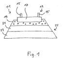
- Rail track 11 shown is the track grid 13 with rails 15 and sleepers 17 laid in a track bed 19 made of gravel.
- the track bed 19 is applied to a protective layer 21 and this in turn on the substrate 23.
- the protective layer 21 may be, for example, a layer protection layer of a grain mixture.
- the protective layer 21 and the substrate 23 together form a substructure 25 of the rail track 11, which may comprise further layers depending on the design. If the substructure 25 more Layers, these may be separated by geopressure layers or the like.
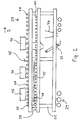
- This in Fig. 2 illustrated railroad work vehicle 27 comprises a chassis 29 carried by a chassis 31 and a plurality of worn by the chassis 31 working equipment, of which only an excavating device 33 and a mounting device 34 are shown by way of example.
- the chassis 29 is a rail undercarriage in the illustrated embodiment. Instead of a rail chassis or in addition to a rail chassis, a ground gear, e.g. a crawler undercarriage, be provided. This makes it possible for the railroad work vehicle 27, at a new production of a railroad track at least in its seen in the direction of the front part to operate without a track.
- a ground gear e.g. a crawler undercarriage
- a transport path 35 is provided on which transport bodies 36 for goods can be moved along the railway work vehicle 27.
- the transport path 35 is here designed as a roller conveyor with rollers 37, on which the trained as boxes transport body 36 can be moved.
- the rollers 37 or at least individual rollers 37 can be driven in rotation. It should be noted that in Fig. 2 merely by way of example a single transport track 35 is shown.
- the plurality of transport paths for example, parallel to one another next to each other and / or arranged one above the other.
- the transport bodies 36 can accommodate all types of goods, in particular working materials such as gravel, sand, gravel, cement, sleepers, iron, platelets, asphalt, soil conditioning substances, piling and signal foundations, but also supplies such as fuel and water. They can serve both to supply and to dispose of the working devices 33, 34 of the railway work vehicle 27.
- working materials such as gravel, sand, gravel, cement, sleepers, iron, platelets, asphalt, soil conditioning substances, piling and signal foundations, but also supplies such as fuel and water. They can serve both to supply and to dispose of the working devices 33, 34 of the railway work vehicle 27.
- the transport body 36 can be loaded, for example, via an unillustrated conveyor belt with excavated material of the excavating device 33.
- conveyor belt may be provided, which can be filled, for example via a corresponding filling with material from the transport bodies 36.
- a likewise not shown device for emptying the transport container 36 may be provided at a filling position.
- the existing railroad grating 13 is first removed by the railway work vehicle 27.
- the iron is automatically solved by a corresponding, preferably in the railway work vehicle 27 integrated device.
- the used rails 15 are spread out from the sleepers 17 and deposited on a rail conveyor track 39 provided laterally on the chassis 31 of the railroad work vehicle 27.
- the rail conveyor track 39 like the transport track 35, has rollers 37, of which optionally at least some are rotatably drivable. If desired, therefore, the stored used rails 15 can be transported away directly in or against the working direction I.
- the used sleepers 17 are picked up by a suitable device integrated into the railroad work vehicle 27 and brought into one or more of the transport bodies 36.
- the transport body 36 By means of the transport body 36, the used sleepers 17 can be easily transported away on the transport path 35 in or against the working direction I. If the used sleepers 17 can not be transported because of their poor condition, they can also be deposited next to the rail track 11 and can only be picked up manually after the remediation process has been completed.
- the excavating device 33 optionally in conjunction with other devices used.
- the gravel of the developed track bed 19 and the material of the developed layers of the substructure 25 is placed in one or more of the transport body 36 and transported on the transport path 35 either for disposal or fed to a recycling process.
- the process ends here. Otherwise, the soil will be watered as needed, conditioned and compacted by applying lime or cement. Subsequently, a new substructure 25 is installed, for example by means of the installation device 34.
- at least one protective layer 21 is incorporated, preferably in several thin layers. The material required for this purpose is transported in transport bodies 36 on the transport path 35.
- a new track bed 19 is installed and compacted as needed.
- the ballast for the track bed 19 is in turn transported in transport bodies 36 on the transport path 35.
- new sleepers 17 are placed in the track bed 19. Subsequently, new rails 15 are transported to the rail conveyor track 39 and automatically threaded into the rail storage of the stored sleepers 17.
- the preferably automatic transport of the new rails 15 can in this case on a further, in Fig. 2 invisible rail conveyor on the other side of the railway work vehicle 27.
- two superimposed rail conveyor tracks 39 may be provided on each side of the railway work vehicle.
- further rail conveyor tracks 39 are provided, on which a transport of long rails through the railway work vehicle 27 can take place.
- corresponding switches may be provided.
- three pairs of rail conveyor tracks 39 may be provided, one of the pairs serving to convey a pair of rails through the entire railroad work vehicle 27. This makes it possible to deliver the rails 15 for the track grid 13 to be installed, depending on the requirements with respect to the working direction I either from the front or from the back or transport the rails 15 of the removed track grid 13 either forward or backward.
- the small iron are screwed and if necessary, the rehabilitated railroad track 11 is stuffed once or several times and / or dynamically stabilized.
- the invention enables the renewal, rebuilding or removal of a rail track 11, including an improvement of the substructure 25, in a single continuous process by means of a single, possibly modular machine or by means of a single machine complex.
- This in Fig. 2 illustrated railroad work vehicle 27 may form a module of a Eisenbahnarbeitszuges, according to the invention more such modules can be assembled.
- each module may have different working devices, but it can also be two or more identical modules are put together.
- the transport paths 35 and the rail conveyor tracks 39 of the modules are preferably designed so that the transport paths of several modules form a continuous transport path.
- the transport lanes form with appropriate transport paths of other rail vehicles a continuous transport path, for example, with supply and / or Entsorgungsbergn.
- the supply and removal of material to or from the railroad work vehicle 27 can take place by means of a train of several rail vehicles 28 coupled together, which will be described below with additional reference to FIG Fig. 3 be described in more detail.
- the railway vehicle 28 is designed in principle similar to the railway work vehicle 27. However, it is designed as a simple railroad car with a rail 29 and has no working facilities.
- a transport path 35 is provided, on which the transport bodies 36 are movable.
- the transport path 35 is in turn designed as a roller conveyor with rollers 37. It can also be provided further transport paths, wherein the plurality of transport paths, for example, parallel to one another next to each other and / or arranged one above the other.
- a rail conveyor track 39 is provided, which has like the transport path 35 rollers 37.
- the transport track 35 and the rail conveyor track 39 are designed such that transport body 36 and rails 15 are movable on continuous tracks of railway vehicle 28 to railway vehicle 28 and of a railway vehicle 28 to the railway work vehicle 27 when a train of railway vehicles 28 in Fig. 2 from the left to the railroad work vehicle 27 is coupled.
Description
Die vorliegende Erfindung betrifft ein Verfahren zum Neuherstellen, Sanieren oder Rückbauen einer Schienenfahrbahn, welche einen Unterbau, eine Gleisbettung und einen darauf verlegten Gleisrost mit Schienen und Schwellen umfasst, wobei das Verfahren folgende Schritte umfasst:
- (i) Einbauen eines Unterbaus oder eines Teils eines Unterbaus;
- (ii) Einbauen einer Gleisbettung; und
- (iii) Einbauen eines Gleisrosts;
- (iv) Ausbauen eines vorhandenen Gleisrosts;
- (v) Ausbauen einer vorhandenen Gleisbettung; und
- (vi) Ausbauen eines vorhandenen Unterbaus oder Teils eines Unterbaus,
- (i) installing a substructure or part of a substructure;
- (ii) installing a track bedding; and
- (iii) installing a track grate;
- (iv) removing an existing track grate;
- (v) removing an existing track bedding; and
- (vi) removing an existing substructure or part of a substructure,
Im Gleisbau sind so genannte Schnellumbauverfahren bekannt, bei welchen die Schwellen und Schienen eines zu erneuernden Gleisrosts ausgetauscht werden. Der Schotter der Gleisbettung wird hierbei umgelagert, jedoch nicht gereinigt oder ausgetauscht. Eine gewünschte Schotterreinigung kann in einem separaten Arbeitsgang mit einer speziellen Maschine erfolgen, welche den gebrauchten Schotter der Gleisbettung aufnimmt, aufbereitet und unmittelbar anschließend wieder einbaut.In track construction, so-called rapid conversion methods are known in which the sleepers and rails of a track grid to be replaced are replaced. The ballast of the track bedding is hereby relocated, but not cleaned or replaced. A desired ballast cleaning can be done in a separate operation with a special machine, which receives the used ballast of the track bedding, processed and immediately afterwards reinstalled.
Häufig ist es erforderlich, nicht nur die Gleisbettung zu erneuern, sondern auch den zugehörigen Unterbau, das so genannte Planum. Hierbei ist üblicherweise neben der Schotterschicht der Gleisbettung wenigstens eine weitere Schicht neu einzubauen oder auszutauschen, beispielsweise eine Schutzschicht, eine Tragschicht oder eine Anordnung mehrerer aufeinanderfolgender Schutz- oder Tragschichten. Oft wird hierbei ein nicht tragfähiger Untergrund ausgebaut und durch einen tragfähigeren Tragschichtaufbau ersetzt. Hierdurch kann die Tragstabilität der Schienenfahrbahn erhöht werden.Often it is necessary not only to renew the track bedding, but also the associated substructure, the so-called Planum. Here, in addition to the ballast layer of the track bedding, it is customary to install or replace at least one further layer, for example a protective layer, a base layer or an arrangement of a plurality of successive protective or base layers. Often this is a non-sustainable substrate removed and replaced by a more sustainable base course structure. As a result, the load-bearing stability of the rail track can be increased.
Dadurch dass der Gleisrost und die Gleisbettung in einem einzigen Arbeitsgang ein- und/oder ausgebaut werden, kann die Anzahl und die Dauer der Gleissperrungen verringert werden. Bezogen auf den gesamten Gleisneubau oder -umbau kann eine wesentlich höhere Leistungsfähigkeit erzielt werden als bei einer zeitlichen oder räumlichen Trennung der gleisrost- und gleisbettungsbezogenen Arbeiten.The fact that the track grid and the track bedding in a single operation and / or removed, the number and duration of the track closures can be reduced. With regard to the entire track construction or conversion, a significantly higher performance can be achieved than with a temporal or spatial separation of the track grating and track bed related work.
Es ist darauf hinzuweisen, dass der Begriff "Arbeitsgang" im Zusammenhang mit der vorliegenden Erfindung nicht im Sinne von "Arbeitsschritt" zu verstehen ist. Konkret umfassen die gleisrost- und gleisbettungsbezogenen Arbeiten üblicherweise mehrere einzelne Arbeitsschritte. Unter einem Durchführen von Arbeiten in einem einzigen Arbeitsgang ist demgegenüber das Erledigen aller erforderlichen Arbeitsschritte in unmittelbarer zeitlicher Abfolge zu verstehen.It should be noted that the term "operation" in the context of the present invention is not to be understood as "work step". Specifically, the track grating and track bed related work typically involves several individual work steps. By doing work in a single operation, on the other hand to understand the completion of all required work steps in the immediate chronological order.
Die
In der
Die
In der
Ein weiteres Eisenbahnarbeitsfahrzeug ist in
Ein Problem bei bestehenden Gleisumbausystemen besteht darin, dass lediglich vorhandenes, gegebenenfalls aufbereitetes Material für das Schotterbett und die Unterbauschichten verwendet werden kann. Falls dieses bereits einen starken Verschleiß aufweist, kann es sein, dass die sanierte Schienenfahrbahn nicht die gewünschte Stabilität aufweist. Darüber hinaus ist es schwierig, die unterschiedlichen Arbeitsgänge "Gleisrosterneuerung", "Schotterbettreinigung" und "Planumsverbesserung" einschließlich des entsprechenden Maschineneinsatzes zu koordinieren. Zudem ist die Leistung bestehender Sanierungsmaschinen lediglich gering. Dies gilt insbesondere für diskontinuierlich arbeitende Maschinen, welche z.B. einen Gleisrost jochweise, also Stück für Stück, auswechseln.A problem with existing track-laying systems is that only existing, possibly recycled, material can be used for the ballast bed and sub-base layers. If this already has a strong wear, it may be that the rehabilitated railroad track does not have the desired stability. In addition, it is difficult to coordinate the various operations of "track-track renewal", "ballast bed cleaning" and "track-improvement" including the corresponding machine use. In addition, the performance of existing refurbishment machines is low. This applies in particular to discontinuously operating machines, which, for example, replace a track grate on a yoke basis, that is, piece by piece.
Es ist eine Aufgabe der Erfindung, ein schnelleres, flexibleres und effektiveres Neuherstellen, Sanieren oder Rückbauen von Schienenfahrbahnen zu ermöglichen.It is an object of the invention to enable a faster, more flexible and more effective new production, rehabilitation or disassembly of railways.
Die Lösung der Aufgabe erfolgt durch ein Verfahren zum Neuherstellen, Sanieren oder Rückbauen einer Schienenfahrbahn mit den Merkmalen des Anspruchs 1.The object is achieved by a method for the new production, renovation or dismantling of a railroad track with the features of claim 1.
Erfindungsgemäß ist vorgesehen, dass bei dem Arbeitsgang des Einbauens des Unterbaus oder Teils des Unterbaus, des Gleisrosts und der Gleisbettung Material für die einzubauende Gleisbettung, wie Neuschotter, und gleichzeitig Material für den einzubauenden Unterbau oder Teil des Unterbaus, wie neuer Sand oder neuer Kies, gleisgebunden antransportiert wird und/oder dass bei dem Arbeitsgang des Ausbauens des vorhandenen Gleisrosts, der vorhandenen Gleisbettung und des vorhandenen Unterbaus oder Teils des Unterbaus Material der ausgebauten Gleisbettung, wie Altschotter, und gleichzeitig Material des ausgebauten Unterbaus oder Teils des Unterbaus, wie Altsand oder altes Erdreich, gleisgebunden abtransportiert wird. Dadurch entfällt die Beschränkung auf vor Ort vorhandenes gebrauchtes Material. Aufgrund des gleisgebundenen Antransports ist auch in Bereichen einer Schienenfahrbahn, deren Umgebung nicht oder schlecht zugänglich ist, die Versorgung mit Neumaterial möglich.According to the invention, during the operation of installing the substructure or part of the substructure, the track grid and the track bedding, material for the track bedding to be installed, such as new ballast, and at the same time material for the substructure or part of the substructure to be installed, such as new sand or new gravel, be transported on track and / or that in the operation of removing the existing track grid, the existing track bedding and the existing substructure or part of the substructure material of the developed track bedding, such as old ballast, and at the same time material of the removed substructure or part of the substructure, such as old sand or old Soil, transported by rail. This eliminates the restriction to on-site existing used material. Due to the track-bound transport, the supply of new material is also possible in areas of a railroad, the environment of which is not accessible or difficult to access.
Weiterbildungen der Erfindung sind in den abhängigen Ansprüchen, der Beschreibung sowie der beigefügten Zeichnung angegeben.Further developments of the invention are specified in the dependent claims, the description and the accompanying drawings.
Bevorzugt ist vorgesehen, dass das gleisgebundene Antransportieren von Material für die einzubauende Gleisbettung, von Material für den einzubauenden Gleisrost und von Material für den einzubauenden Unterbau oder Teil des Unterbaus gleichzeitig erfolgt und/oder dass das gleisgebundene Abtransportieren von Material des ausgebauten Gleisrosts, von Material der ausgebauten Gleisbettung und von Material des ausgebauten Unterbaus oder Teils des Unterbaus gleichzeitig erfolgt. Hierdurch kann die Bauzeit erheblich verkürzt werden.It is preferably provided that the track-bound transporting material for the track bedding to be installed, material for the track grid to be installed and material for the substructure or part of the substructure to be installed takes place at the same time and / or that the track-bound removal of material of the removed track grid, material of the dismantled track bedding and made of material of the removed substructure or part of the substructure at the same time. As a result, the construction time can be shortened considerably.
Ferner kann vorgesehen sein, dass das gleisgebundene Antransportieren von Material für die einzubauende Gleisbettung und von Material für den einzubauenden Unterbau oder Teil des Unterbaus ohne Zwischenlagerung erfolgt und/oder dass das gleisgebundene Abtransportieren von Material der ausgebauten Gleisbettung und von Material des ausgebauten Unterbaus oder Teils des Unterbaus ohne Zwischenlagerung erfolgt.Furthermore, it can be provided that the track-bound transporting material for the track bedding to be installed and material for the substructure or part of the substructure to be installed takes place without intermediate storage and / or that the track-bound removal of material of the dismounted track bedding and of the removed substructure or part of the Substructure without intermediate storage takes place.
Das gleisgebundene Antransportieren und/oder Abtransportieren von Material kann auf wenigstens einer Transportbahn eines Eisenbahnfahrzeugs durchgeführt werden, auf welcher Transportkörper für Gegenstände oder Transportkörper bildende Gegenstände in Form von Stückgut längs des Eisenbahnfahrzeugs verfahrbar sind.The track-bound transport and / or removal of material may be on at least one transport path of a railway vehicle be performed on which transport body for objects or transport body forming objects in the form of cargo along the railway vehicle are movable.
Gemäß einer Ausgestaltung der Erfindung wird bei dem Arbeitsgang des Einbauens des Unterbaus oder Teils des Unterbaus, des Gleisrosts und der Gleisbettung wenigstens eine Schutzschicht für den Unterbau, insbesondere eine Planumsschutzschicht, eine Frostschutzschicht und/oder eine Wasserschutzschicht, eingebaut. Solche zusätzlichen Unterbauschichten können z.B. Sand, Kies, spezielle Korngemische wie KG1 und KG2 und/oder Asphalt umfassen. Die entsprechenden Materialien werden vorzugsweise ebenfalls im Neuzustand gleisgebunden antransportiert, beispielsweise in Transportbehältern auf einer Transportbahn der den Umbau durchführenden Maschine. Durch das Einbringen zusätzlicher Schichten in den Unterbau kann die Stabilität der Schienenfahrbahn beträchtlich verbessert werden, insbesondere dann, wenn Neumaterial verwendet wird.According to one embodiment of the invention, in the operation of installing the substructure or part of the substructure, the track grid and the track bedding at least one protective layer for the substructure, in particular a layer protection layer, an antifreeze layer and / or a water protection layer installed. Such additional sub-layers may e.g. Sand, gravel, special grain mixtures such as KG1 and KG2 and / or asphalt. The corresponding materials are preferably also transported in new condition track-bound, for example, in transport containers on a transport path of the conversion performing machine. By incorporating additional layers into the substructure, the stability of the railroad track can be significantly improved, especially if virgin material is used.
Es können auch mehrere Schutzschichten für den Unterbau eingebaut werden, wobei wenigstens zwischen zwei der mehreren Schutzschichten eine Trennschicht eingebaut wird, welche insbesondere ein Geotextil- und/oder ein Hartschaummaterial umfasst. Solche Trennschichten können einer unerwünschten Vermischung der Materialien benachbarter Schutzschichten entgegenwirken. Außerdem kann so verhindert werden, dass der unter den Tragschichten anliegende Boden sich mit der untersten Tragschicht vermischt und diese dadurch verschmutzt sowie in ihrer Tragfähigkeit beeinträchtigt wird.It is also possible to install a plurality of protective layers for the substructure, wherein at least between two of the plurality of protective layers a separating layer is incorporated, which in particular comprises a geotextile and / or a rigid foam material. Such separation layers can counteract unwanted mixing of the materials of adjacent protective layers. In addition, it can be prevented so that the voltage applied under the base layers soil mixes with the bottom layer of support and this is dirty and impaired in their capacity.
Weiterhin kann die Oberfläche der eingebauten Schutzschicht oder der mehreren eingebauten Schutzschichten versiegelt werden, insbesondere durch Aufbringen von Zement. Hierdurch kann ein Eindringen von Wasser in die Schutzschicht verhindert werden.Furthermore, the surface of the built-in protective layer or the plurality of built-in protective layers can be sealed, in particular by applying cement. In this way, penetration of water into the protective layer can be prevented.
Gemäß einer weiteren Ausgestaltung der Erfindung werden die eingebaute Schutzschicht oder die mehreren eingebauten Schutzschichten wenigstens einfach armiert, insbesondere unter Verwendung eines Geogitters, einer Metallmatte oder eines Streckblechs. Der Unterbau kann hierdurch verstärkt werden.According to a further embodiment of the invention, the built-in protective layer or the plurality of incorporated protective layers are at least simply reinforced, in particular using a geogrid, a metal mat or a stretch sheet. The substructure can thereby be reinforced.
Gemäß einer Ausführungsform der Erfindung werden die eingebaute Schutzschicht oder die mehreren eingebauten Schutzschichten unter Verwendung einer Metallmatte armiert, welche während des Neuherstellens oder Sanierens der Schienenfahrbahn aus Drähten gefertigt wird. Die Drähte können hierbei auf der betreffenden Maschine mitgeführt oder gleisgebunden zugeführt werden, sodass das Armieren ohne Zeitverzug kontinuierlich erfolgen kann. Eine spezielle Ausgestaltung der Erfindung sieht vor, dass einzelne mitgeführte oder gleisgebunden zugeführte Drähte vor dem Einbau in der betreffenden Maschine zu einem Gitter verschweißt werden.According to one embodiment of the invention, the built-in protective layer (s) are reinforced using a metal mat which is made of wires during rebuilding or rehabilitation of the railroad track. The wires can be carried along on the relevant machine or fed by rail, so that the reinforcement can be carried out continuously without time delay. A special embodiment of the invention provides that individual entrained or tracked supplied wires are welded to a grid before installation in the machine in question.
Alternativ oder zusätzlich können die eingebaute Schutzschicht oder die mehreren eingebauten Schutzschichten unter Verwendung eines Streckblechs armiert werden, welches während des Neuherstellens oder Sanierens der Schienenfahrbahn durch Recken eines Coils hergestellt wird.Alternatively or additionally, the built-in protective layer or layers may be reinforced using a stretched sheet produced by re-forming a coil during the rebuilding or rehabilitation of the railroad track.
Vorzugsweise wird wenigstens eine einzubauende Schutzschicht in mehreren Teilschichten eingebaut, wobei vorzugsweise jede Teilschicht vor dem Aufbringen einer nachfolgenden Teilschicht verdichtet wird. Das Verdichten kann mit einem profilierten Verdichtungselement erfolgen, um eine starke Verzahnung der Schichten untereinander zu bewirken. Das schrittweise Einbringen einer Schutzschicht in mehreren, vergleichsweise dünnen Teilschichten erleichtert den Verdichtungsvorgang.Preferably, at least one protective layer to be incorporated is incorporated in a plurality of partial layers, wherein preferably each partial layer is compacted before the application of a subsequent partial layer. The compaction can be done with a profiled compression element to effect a strong interlocking of the layers with each other. The Gradual introduction of a protective layer in several, relatively thin sub-layers facilitates the compression process.
Weiterhin kann wenigstens eine eingebaute Schutzschicht oder Teilschicht einer Schutzschicht vor dem Aufbringen einer nachfolgenden Schutzschicht oder Teilschicht der gleichen Schutzschicht aufgerauht werden. Hierdurch kann der Verzahnungseffekt zwischen einzelnen Schichten oder Teilschichten verbessert und so die Gesamtstabilität des Unterbaus erhöht werden. Insbesondere kann bei einem Verdichten einer Schicht ein Profil erzeugt werden, welches einen Verzahnungseffekt begünstigt.Furthermore, at least one built-in protective layer or partial layer of a protective layer can be roughened before the application of a subsequent protective layer or partial layer of the same protective layer. As a result, the interlocking effect between individual layers or partial layers can be improved and thus the overall stability of the substructure can be increased. In particular, when a layer is compacted, a profile can be produced which favors a toothing effect.
Gemäß einer weiteren Ausführungsform der Erfindung wird während des Einbauens des Unterbaus oder Teils des Unterbaus die Anzahl und die Dicke der eingebauten Schutzschichten in Abhängigkeit von der Beschaffenheit des Bodens verändert. Die eingebauten Schichten können so dynamisch an die sich ändernden Bodenverhältnisse angepasst werden.According to a further embodiment of the invention, during the installation of the substructure or part of the substructure, the number and the thickness of the incorporated protective layers are changed depending on the nature of the soil. The built-in layers can be dynamically adapted to the changing soil conditions.
Es kann vorgesehen sein, dass das Einbauen des Unterbaus oder Teils des Unterbaus, des Gleisrosts und der Gleisbettung mittels eines Eisenbahnarbeitsfahrzeugs durchgeführt wird, wobei wenigstens eine auf dem Eisenbahnarbeitsfahrzeug mitgeführte Bahn aus einem Geowerkstoff, insbesondere einem Geokunststoff, einer Geotextilie oder einem Geoverbundstoff, in den Unterbau oder Teil des Unterbaus eingebaut wird. Gegenüber dem auf dem Fachgebiet üblichen Vorgehen, Bahnen aus Geowerkstoff separat anzuliefern und vor dem Baubeginn entlang der Schienenfahrbahn bereitzulegen, kann durch das Mitführen der Bahnen auf der Gleisbaumaschine selbst die Bauzeit beträchtlich verkürzt werden. Ein besonderer Vorteil besteht darin, dass Gleissperrungen für diejenigen Schienenfahrzeuge, welche die Bahnen anliefern, vermieden werden können. Ferner müssen bei herkömmlicher Vorgehensweise die bereitgelegten Bahnen per Hand in eine Verlegevorrichtung der Gleisbaumaschine eingebracht werden, was nur bei stillstehender Maschine erfolgen kann und für das Baupersonal anstrengend ist. Diese Nachteile können durch das Mitführen der Geowerkstoff-Bahnen auf der Gleisbaumaschine vermieden werden.It can be provided that the installation of the substructure or part of the substructure, the track grid and the track bedding is carried out by a railway work vehicle, wherein at least one carried on the railway work vehicle track of a geo-material, in particular a geosynthetic material, a geotextile or a Geoverbundstoff, in the Substructure or part of the substructure is installed. Compared with the procedure customary in the field of supplying webs of geoparticulate separately and laying them out before commencement of construction along the railroad track, the construction time itself can be considerably shortened by carrying along the webs on the track construction machine itself. A particular advantage is that track closures can be avoided for those rail vehicles that deliver the trains. Furthermore, in the conventional procedure, the prepared Railways are introduced by hand in a laying device of the track construction machine, which can only be done with the machine stopped and is tiring for the construction staff. These disadvantages can be avoided by carrying the geo-material webs on the track-laying machine.
Die wenigstens eine Bahn aus Geowerkstoff kann insbesondere in aufgerolltem und/oder gefaltetem Zustand auf dem Eisenbahnarbeitsfahrzeug mitgeführt und zum Einbauen automatisch entnommen werden. Beispielsweise kann die Bahn einmal vollständig in Längsrichtung gefaltet und anschließend entweder gerollt oder in Querrichtung gefaltet werden. Vor dem Einbau kann die Bahn dann mittels einer geeigneten Vorrichtung wieder automatisch abgerollt bzw. entfaltet werden. Sobald die Bahn vollständig verlegt ist, wird vorzugsweise eine auf dem Eisenbahnarbeitsfahrzeug mitgeführte weitere Bahn automatisch bereitgestellt. Bevorzugt wird auch das Einfädeln dieser weiteren Bahn automatisch durchgeführt.The at least one web of geo-material can in particular be carried along in the rolled-up and / or folded state on the railway work vehicle and automatically removed for installation. For example, the web can be folded once completely in the longitudinal direction and then either rolled or folded in the transverse direction. Before installation, the web can then be automatically unrolled or unfolded by means of a suitable device. Once the web has been completely laid, preferably a further web carried on the railroad work vehicle is automatically provided. Preferably, the threading of this further web is carried out automatically.
Weiterhin kann die wenigstens eine Bahn aus Geowerkstoff als um eine Spulenachse gewickelte Rolle auf dem Eisenbahnarbeitsfahrzeug mitgeführt werden, wobei die Spulenachse parallel zur Arbeitsrichtung des Eisenbahnarbeitsfahrzeugs verläuft und die Bahn zum Verlegen automatisch abgerollt und gedreht wird, vorzugsweise um 90°. Dies trägt dem Umstand Rechnung, dass gängige Geowerkstoff-Bahnen bedeutend breiter sind als das zum Transport vorgesehene Eisenbahnarbeitsfahrzeug. Aufgrund der Lagerung der entsprechenden Rolle quer zur Abrollrichtung kann die Rolle selbst im Prinzip beliebig breit sein.Furthermore, the at least one web of geo-material may be carried on the railway work vehicle as a reel wound around a reel axis, the reel axis being parallel to the working direction of the railway work vehicle and the web automatically being unrolled and rotated for laying, preferably by 90 °. This takes into account the fact that common geo-material webs are significantly wider than the railroad work vehicle intended for transport. Due to the storage of the corresponding role transverse to the unwinding direction, the roller itself can in principle be arbitrarily wide.
Gemäß einer besonderen Ausgestaltung der Erfindung werden mittels einer automatischen Verlegevorrichtung des Eisenbahnarbeitsfahrzeugs mehrere Bahnen aus Geowerkstoff nebeneinander verlegt. Dadurch genügt es, relativ schmale Rollen auf dem Eisenbahnarbeitsfahrzeug mitzuführen, was hinsichtlich der Lagerung und der Handhabbarkeit von beträchtlichem Vorteil ist. Insbesondere sind solche schmalen Rollen je nach Bedarf sowohl in Fahrtrichtung als auch quer zur Fahrtrichtung transportierbar und abrollbar.According to a particular embodiment of the invention, multiple webs of geo material are laid side by side by means of an automatic laying device of the railway work vehicle. This is enough to carry relatively narrow rollers on the railway work vehicle, which is a considerable advantage in terms of storage and handling. In particular, such narrow rollers can be transported and unrolled as needed both in the direction of travel and transversely to the direction of travel.
Ferner kann während des Ausbauens des vorhandenen Unterbaus oder Teils des Unterbaus die Gleisbettung einer benachbarten Schienenfahrbahn abgestützt werden, insbesondere durch einen mitlaufenden Verbau. Dies ist insbesondere dann von Vorteil, wenn die Gesamtstärke der aus- und einzubauenden Schichten des Unterbaus eine vorgegebene Grenze überschreitet.Furthermore, during the removal of the existing substructure or part of the substructure, the track bedding of an adjacent rail track can be supported, in particular by a follower shoring. This is particularly advantageous if the total thickness of the layers to be removed and installed in the substructure exceeds a predetermined limit.
Gemäß einer weiteren Ausführungsform der Erfindung wird zum Einbauen des Unterbaus oder Teils des Unterbaus ein Material verwendet, welches bei dem Arbeitsgang des Ausbauens des vorhandenen Unterbaus oder Teils des Unterbaus entnommen wurde. Hierdurch kann die Menge an zu förderndem Neumaterial verringert werden oder es kann völlig auf das Zuführen von Neumaterial verzichtet werden.According to a further embodiment of the invention, a material is used for installing the substructure or part of the substructure, which material was taken during the operation of dismantling the existing substructure or part of the substructure. As a result, the amount of new material to be promoted can be reduced or it can be completely dispensed with the supply of virgin material.
Bei Bedarf kann nach dem Ausbauen des vorhandenen Unterbaus oder Teils des Unterbaus und vor dem Einbauen des Unterbaus oder Teils des Unterbaus der Boden durch Aufbringen eines vorzugsweise schüttfähigen Stabilisierungsmittels, insbesondere Kalk oder Zement, konditioniert werden, wobei insbesondere das Stabilisierungsmittel gleisgebunden antransportiert wird. Hierdurch kann die Belastungsfähigkeit der Schienenfahrbahn weiter erhöht werden.If necessary, after removing the existing substructure or part of the substructure and before installing the substructure or part of the substructure, the soil can be conditioned by applying a preferably pourable stabilizing agent, in particular lime or cement, in particular the stabilizing agent being transported by rail. As a result, the load capacity of the rail carriageway can be further increased.
Es ist bevorzugt, dass die Schienen für den einzubauenden Gleisrost gleisgebunden antransportiert werden und/oder dass die Schienen des ausgebauten Gleisrosts gleisgebunden abtransportiert werden, insbesondere jeweils ohne Zwischenablage der Schienen auf dem Boden. Dies erhöht die Effizienz des Gesamtprozesses.It is preferred that the rails for the rail track to be installed are transported by rail and / or that the rails of the removed rail track removed, especially in each case without clipboard rails on the ground. This increases the efficiency of the overall process.
Die Schienen des ausgebauten Gleisrosts können dabei vor dem Abtransport zerteilt werden, um eine bessere Handhabbarkeit zu gewährleisten.The rails of the removed track grid can be divided before removal to ensure better handling.
Gemäß einer weiteren Ausgestaltung der Erfindung ist vorgesehen, dass die Schienen für den einzubauenden Gleisrost gemeinsam mit Material für die einzubauende Gleisbettung und/oder für den einzubauenden Unterbau oder Teil des Unterbaus, wie Neuschotter oder Neusand, gleisgebunden antransportiert werden und/oder dass die Schienen des ausgebauten Gleisrosts gemeinsam mit Material der ausgebauten Gleisbettung und/oder des ausgebauten Unterbaus oder Teils des Unterbaus, wie Altschotter oder Altsand, gleisgebunden abtransportiert werden. Der Ablauf der gesamten Gleiserstellung, Gleisentfernung oder Gleissanierung kann dadurch weiter beschleunigt werden. Der Transport kann auf einer oder mehreren Transportbahnen des den Gleisumbau durchführenden Eisenbahnarbeitsfahrzeugs erfolgen, wobei in vorteilhafter Weise Schüttgüter in eigens dafür vorgesehenen Transportbehältern und Stückgüter wie Schienen, Schwellen und Gleisroststücke auf ein und derselben Transportbahn gefördert werden.According to a further embodiment of the invention, it is provided that the rails for the track grid to be installed are transported by rail together with material for the track bedding to be installed and / or for the substructure or part of the substructure to be installed, such as new gravel or new sand, and / or that the rails of the removed track grid together with material of the dismantled track bedding and / or the dismantled substructure or part of the substructure, such as old gravel or used sand, be transported track-bound. The process of the entire track creation, track removal or track rehabilitation can be further accelerated. The transport can be carried out on one or more transport lanes of the railway track conversion work vehicle, advantageously bulk goods are transported in specially provided transport containers and cargo such as rails, sleepers and track grating pieces on one and the same transport path.
Vorzugsweise erfolgt der An- und/oder Abtransport der Schienen ohne Verletzung des Lichtraums eines in einer benachbarten Schienenfahrbahn fahrenden Zuges. Das Gegengleis der zu erstellenden, zu sanierenden oder rückzubauenden Schienenfahrbahn muss somit zur Durchführung der Baumaßnahmen nicht gesperrt werden.Preferably, the arrival and / or removal of the rails takes place without violating the clearance of a train traveling in an adjacent railroad track. The opposite track to be created, to be renovated or disassembled railroad track must therefore not be blocked to carry out the construction work.
Gemäß einer weiteren Ausführungsform der Erfindung wird nach dem Ausbauen des vorhandenen Unterbaus oder Teils des Unterbaus und vor dem Einbauen des Unterbaus oder Teils des Unterbaus der Boden verdichtet, um eine stabilere Grundlage für die zu erstellende Schienenfahrbahn zu schaffen.According to a further embodiment of the invention, after the existing substructure or part of the substructure has been removed and prior to installing the substructure or part of the substructure, the soil is compacted to provide a more stable foundation for the railroad track to be created.
Ferner wird gemäß einer Ausgestaltung der Erfindung die Feuchtigkeit des zu verdichtenden Bodens gemessen und vor dem Verdichten in Abhängigkeit von der gemessenen Feuchtigkeit bedarfsweise Wasser in bereitgestelltes Material für den einzubauenden Unterbau oder Teil des Unterbaus eingebracht. Somit kann die Feuchtigkeit des Bodens exakt an die Anforderungen des Verdichtungsprozesses angepasst werden. Ebenso kann die Feuchtigkeit von einzubauendem Material gemessen und bei Bedarf angepasst werden.Further, according to one embodiment of the invention, the moisture of the soil to be compacted is measured and, prior to compaction, water is introduced into provided material for the substructure or part of the substructure to be installed, depending on the measured moisture. Thus, the moisture of the soil can be adapted exactly to the requirements of the compaction process. Likewise, the moisture of the material to be installed can be measured and adjusted as needed.
Bei bestimmten Anwendungen kann es bevorzugt sein, dass beim Verdichten eine Messgröße, insbesondere die Beschleunigung, eines Verdichterelements erfasst wird und wenigstens ein Verdichtungsparameter in Abhängigkeit von der erfassten Messgröße angepasst wird. Auf diese Weise ist eine permanente Verdichtungskontrolle möglich. Bei Bedarf kann der Verdichtungsprozess mit einer entsprechenden Steuereinrichtung gesteuert werden. Weiterhin können die erfassten Daten für eine spätere Verwendung kontinuierlich gespeichert werden.In certain applications, it may be preferred that during compaction a measured variable, in particular the acceleration, of a compressor element is detected and at least one compression parameter is adjusted as a function of the detected measured variable. In this way, a permanent compression control is possible. If necessary, the compression process can be controlled with a corresponding control device. Furthermore, the collected data can be stored continuously for later use.
Gemäß einer weiteren Ausführungsform der Erfindung wird beim Einbauen der Gleisbettung in Abhängigkeit von einer lokalen Belastungssituation Neuschotter, gebrauchter Schotter oder recycelter Schotter verwendet. Z.B. kann an hinsichtlich der Tragfähigkeit wichtigen Stellen, etwa im Bereich des Tragkopfs unter dem Gleis oder vor Kopf gezielt Neuschotter verwendet werden, während an hinsichtlich der Tragfähigkeit weniger wichtigen Stellen, etwa im Bereich der Schwellenmitte oder bei zweigleisigen Schienenfahrbahnen im Bereich zwischen den beiden Richtungsfahrbahnen, gebrauchter Schotter zum Einsatz kommt. Somit kann der Bedarf an Neuschotter gering gehalten werden und dennoch eine hohe Stabilität der Gleisbettung erzielt werden.According to a further embodiment of the invention, when installing the track bed depending on a local load situation, new ballast, used ballast or recycled ballast is used. For example, at points important for carrying capacity, such as in the area of the carrying head under the track or in front of the head, targeted new ballot can be used, while less in terms of carrying capacity important places, such as in the area of the middle of the sleeper or in the case of double-track railways in the area between the two carriageways, used ballast is used. Thus, the need for Neuchotter can be kept low and yet a high stability of the track bedding can be achieved.
Bei Bedarf kann bei dem Arbeitsgang des Einbauens der Gleisbettung der eingebaute Schotter verdichtet werden, insbesondere vor dem Einbauen des Gleisrosts. Bei Bedarf kann der eingebaute Schotter nach dem Einbauen des Gleisrosts gestopft und/oder dynamisch stabilisiert werden. Das Stopfen bzw. das dynamische Stabilisieren kann auch mehrfach wiederholt werden, falls dies erforderlich ist. Dadurch können separate Verdichtungs-, Stopf- und Stabilisierprozesse eingespart werden. Durch eine ausreichende Verdichtung des Grundschotters kann gegebenenfalls ein Stopfdurchgang eingespart werden.If necessary, in the operation of installing the track bed the built-in ballast can be compacted, in particular before installing the track grid. If necessary, the built-in ballast can be stuffed and / or dynamically stabilized after installing the track grid. The plugging or the dynamic stabilization can also be repeated several times, if necessary. As a result, separate compression, stuffing and stabilization processes can be saved. By sufficient compaction of the basic ballast, a stuffing passage can optionally be saved.
Die eingebaute Gleisbettung kann auch profiliert werden, wobei eine solche Profilierung bedarfsweise ebenfalls mehrfach hintereinander erfolgen kann.The built-in track bedding can also be profiled, such profiling, if necessary, can also be done several times in a row.
Gemäß einer weiteren Ausführungsform der Erfindung wird bei dem Arbeitsgang des Einbauens des Gleisrosts die Lage des eingebauten Gleisrosts erfasst und dokumentiert.According to a further embodiment of the invention, the position of the installed track grid is detected and documented during the operation of installing the track grid.
Weiterhin können bei dem Arbeitsgang des Einbauens des Gleisrosts die Kleineisen des eingebauten Gleisrosts geschlossen, insbesondere verschraubt, werden.Furthermore, in the operation of installing the track grid, the small bars of the installed track grid can be closed, in particular screwed.
Für die Durchführung eines wie vorstehend beschriebenen Verfahrens kann insbesondere ein Eisenbahnarbeitsfahrzeug eingesetzt werden. Bevorzugt wird ein einziges Eisenbahnarbeitsfahrzeug für alle Verfahrensschritte eingesetzt.For carrying out a method as described above, in particular a railway work vehicle can be used. Prefers a single railway work vehicle will be used for all process steps.
Die Schienen für den einzubauenden Gleisrost und/oder die Schienen des ausgebauten Gleisrosts können nach einer Ausgestaltung der Erfindung auf einer in oder an einem Eisenbahnfahrzeug, bevorzugt zwischen den Radscheiben, angeordneten Schienenförderbahn durch das Eisenbahnfahrzeug hindurch gefördert werden. Dies erleichtert einen Gleiseinbau und/oder Gleisausbau an schwer zugänglichen Stellen. Ferner kann die Sperrpause für den An- und Abtransport der Langschienen eingespart werden. Dadurch dass die Schienenförderung in dem üblicherweise nur schlecht nutzbaren Lichtraum zwischen den Radscheiben erfolgt, ist der übrige gut nutzbare Lichtraum des Eisenbahnfahrzeugs frei für eine Förderung von weiterem Material, z.B. von Schüttgut in entsprechenden Transportbehältern.The rails for the track grid to be installed and / or the rails of the removed track grid can, according to one embodiment of the invention, be conveyed through the rail vehicle on a rail conveyor track arranged in or on a railway vehicle, preferably between the wheel disks. This facilitates track installation and / or track removal in hard to reach places. Furthermore, the blocking pause for the arrival and removal of the long rails can be saved. By providing rail conveyance in the typically poorly usable clearance space between the wheel discs, the remainder of the well-usable clearance space of the railway vehicle is free to carry further material, e.g. of bulk material in appropriate transport containers.
Gemäß einer Ausführungsform der Erfindung werden die Schienen auf wenigstens einer Schienenförderbahn gefördert, welche an einer Seite des Eisenbahnfahrzeugs vorgesehen ist, wobei die Schienen vorzugsweise auf mehreren übereinander oder nebeneinander angeordneten Schienenförderbahnen gefördert werden. Es können auch an jeder Seite des Eisenbahnfahrzeugs mehrere übereinander oder nebeneinander angeordnete Schienenförderbahnen vorgesehen sein. Somit können z.B. zwei für einen Gleisrost erforderliche Schienen an einer Seite des Eisenbahnfahrzeugs antransportiert werden, während zwei Schienen eines ausgebauten Gleisrosts auf der anderen Seite des Eisenbahnfahrzeugs abtransportiert werden. Im zentralen Bereich des Lichtraums des Eisenbahnfahrzeugs kann dann gleichzeitig Material wie Neuschotter oder Neuschwellen antransportiert und gegebenenfalls gebrauchtes Material wie Altschotter oder Altschwellen abtransportiert werden.According to one embodiment of the invention, the rails are conveyed on at least one rail conveyor track which is provided on one side of the railway vehicle, the rails preferably being conveyed on a plurality of rail conveyor tracks arranged one above the other or side by side. It can also be provided on each side of the railway vehicle several superimposed or juxtaposed rail conveyor tracks. Thus, for example, two rails required for a track grid can be transported to one side of the railway vehicle, while two rails of a removed track grid are transported away on the other side of the railway vehicle. In the central area of the light space of the railway vehicle can then simultaneously material such as new ballast or Neuschwellen transported and possibly used material such as old ballast or old sleepers are transported away.
Es kann bei bestimmten Gleisbauarbeiten günstig sein, dass die Schienen des ausgebauten Gleisrosts, insbesondere seitlich vom Eisenbahnfahrzeug, vom Boden aufgenommen und zum Abtransport auf eine in oder an dem Eisenbahnfahrzeug und vorzugsweise zwischen den Radscheiben angeordnete Schienenförderbahn überführt werden und/oder dass die Schienen für den einzubauenden Gleisrost auf einer in oder an dem Eisenbahnfahrzeug und vorzugsweise zwischen den Radscheiben angeordneten Schienenförderbahn antransportiert und zum Ablegen in einen Bereich seitlich vom Eisenbahnfahrzeug oder unter dem Eisenbahnfahrzeug überführt werden. Die geförderten Schienen können hierbei sowohl zwischen den Schienen des bestehenden Gleises als auch neben den Schienen des bestehenden Gleises aufgenommen oder abgelegt werden. Bevorzugt ist eine Anordnung der Schienenförderbahn oberhalb der Radwellen.It may be favorable for certain track construction work, that the rails of the removed track grid, especially the side of the railway vehicle, taken from the ground and transferred for removal to a rail vehicle or in the rail vehicle and preferably arranged between the wheel discs rail conveyor and / or that the rails for the track grids to be installed are transported on a rail conveyor track arranged in or on the railroad vehicle and preferably between the wheel disks and are transferred laterally from the railway vehicle or under the railroad vehicle to be deposited in an area. The subsidized rails can hereby be taken or stored both between the rails of the existing track and next to the rails of the existing track. An arrangement of the rail conveyor track above the wheel shafts is preferred.
Eine weitere Ausführungsform der Erfindung sieht vor, dass die Schienen mittels einer Zugkraftübertragungseinrichtung, insbesondere Seil, Band oder Kette, auf eine Schienenförderbahn des Eisenbahnfahrzeugs und/oder von dieser herunter gezogen werden, wobei insbesondere ein Einziehen von Zugkraftübertragungseinrichtungen in die Schienenförderbahn mittels von der Schienenförderbahn heruntergezogenen Schienen erfolgt. Dies ermöglicht ein besonders einfaches Überführen der Schienen auf die Schienenförderbahn. Es kann vorgesehen sein, dass ein Seil, ein Band oder eine Kette bereits vor der einzuziehenden Schiene in die Schienenförderbahn eingezogen wird. An einem vorderen Ende der Schiene kann ferner eine Einfädelhilfe, beispielsweise in Form eines pfeilspitzenartigen Bauteils, angebracht werden, um das Einfädeln der Schiene in die Schienenförderbahn zu erleichtern. Ebenso kann am Ende einer Schiene ein Seil befestigt werden. Wenn diese Schiene aus der Schienenförderbahn herausgezogen wird, wird das Seil in die Schienenförderbahn eingezogen. Weiterhin kann es bei bestimmten Anwendungen günstig sein, die Schienen zum gleisgebundenen Antransport und/oder zum gleisgebundenen Abtransport abzulängen und in einen Transportbehälter zu verbringen. Vorzugsweise erfolgt die Förderung der Schienen, insbesondere einschließlich des Ein- und/oder Ausfädelns in das Eisenbahnfahrzeug und/oder in das Schienenlager, automatisch. Dadurch kann der Gesamtprozess weiter beschleunigt werden.A further embodiment of the invention provides that the rails are pulled by means of a traction transfer device, in particular rope, belt or chain, on a rail conveyor of the railway vehicle and / or from this, in particular a retraction of traction transfer devices in the rail conveyor track by means of pulled down from the rail conveyor track Rails done. This allows a particularly simple transfer of the rails on the rail conveyor. It can be provided that a rope, a belt or a chain is pulled into the rail conveyor track before the rail to be pulled in. A threading aid, for example in the form of an arrowhead-type component, can also be attached to a front end of the rail in order to facilitate the threading of the rail into the rail conveyor track. Likewise, at the end of a rail a rope to be attached. When this rail is pulled out of the rail conveyor, the cable is pulled into the rail conveyor. Furthermore, it may be advantageous in certain applications to cut the rails for track-bound transport and / or for track-based removal and spend in a transport container. Preferably, the conveyance of the rails, in particular including the input and / or Ausfädelns in the railway vehicle and / or in the rail warehouse, done automatically. This can further accelerate the overall process.
Bei Bedarf können die Schienen für den einzubauenden Gleisrost und/oder die Schienen des ausgebauten Gleisrosts vorübergehend am Boden abgelegt werden, insbesondere auf am Boden angeordnete Lagerrollen. Solche Lagerrollen vermindern die erforderliche Zugkraft für den Transport der Schienen beträchtlich. Die Lagerrollen können von der die Gleisherstellung, die Gleissanierung oder den Gleisrückbau durchführenden Maschine auf dem Boden platziert und gegebenenfalls nach der Wiederaufnahme der abgelegten Schienen wieder aufgenommen werden.If necessary, the rails for the track grid to be installed and / or the rails of the removed track grid can be temporarily stored on the ground, in particular on bearing rollers arranged on the floor. Such bearing rollers reduce the required tensile force for the transport of the rails considerably. The bearing rollers can be placed on the ground by the machine that is producing the track preparation, the track restoration or the track dismantling and, if necessary, be picked up again after the discarded rails have been taken up again.
Die Erfindung betrifft auch ein Eisenbahnarbeitsfahrzeug gemäss dem vorliegenden Anspruch 18, das zur Durchführung eines Verfahrens wie vorstehend beschrieben ausgebildet ist.The invention also relates to a railway work vehicle according to the present claim 18, which is designed to carry out a method as described above.
Das Eisenbahnarbeitsfahrzeug umfasst wenigstens eine Transportbahn, auf welcher Transportkörper für Gegenstände oder Transportkörper bildende Gegenstände in Form von Stückgut längs des Eisenbahnarbeitsfahrzeugs verfahrbar sind, und ein Baumodul zum Einbauen des Gleisrosts und von Material der Gleisbettung und von Material des Unterbaus oder Teils des Unterbaus und/oder ein Baumodul zum Ausbauen des Gleisrosts und von Material der vorhandenen Gleisbettung und von Material des vorhandenen Unterbaus oder Teils des Unterbaus. Bei Bedarf kann das Eisenbahnarbeitsfahrzeug zusätzlich wenigstens ein von dem Baumodul oder den Baumodulen getrenntes Recyclingmodul zur Reinigung von ausgebautem Material umfassen. Somit kann ein Gleisumbau mit einer Schotterbettreinigung kombiniert werden und so insbesondere die Sperrzeit auf ein Minimum beschränkt werden.The railroad work vehicle comprises at least one transport path on which transport objects for items or transport body forming objects in the form of piece goods along the railway work vehicle are movable, and a structural module for installing the track grid and material of the track bedding and material of the substructure or part of the substructure and / or a structural module for removing the Track grids and material of the existing track bedding and material of the existing substructure or part of the substructure. If desired, the railroad work vehicle may additionally include at least one recycle module separate from the building module or modules for cleaning up removed material. Thus, a track renewal can be combined with a ballast bed cleaning and so in particular the lock time are kept to a minimum.
Weiterhin umfasst das Eisenbahnarbeitsfahrzeug vorzugsweise eine Vorrichtung zum Lösen und/oder zum Befestigen von Kleineisen. Dies erleichtert den kontinuierlichen Einbau des Gleisrosts und Ausbau des vorhandenen Gleisrosts.Furthermore, the railway work vehicle preferably comprises a device for releasing and / or fixing of iron. This facilitates the continuous installation of the track grid and removal of the existing track grid.
Das Eisenbahnarbeitsfahrzeug kann nach einer Ausgestaltung der Erfindung auch eine Vorrichtung zum Aufnehmen und Transportieren der Schienen des ausgebauten Gleisrosts umfassen. Weiterhin kann das Eisenbahnarbeitsfahrzeug eine Verdichtungsvorrichtung wie eine angetriebene Rüttelplatte oder eine Vibrationswalze umfassen. Alternativ oder zusätzlich kann das Eisenbahnarbeitsfahrzeug eine Stopf- und/oder Profilierungsvorrichtung umfassen.The railway work vehicle according to one embodiment of the invention may also include a device for receiving and transporting the rails of the removed track grid. Furthermore, the railroad work vehicle may include a compacting device such as a driven vibratory plate or a vibratory roller. Alternatively or additionally, the railroad work vehicle may include a stuffing and / or profiling device.
Ein Ausführungsbeispiel der Erfindung ist in den Zeichnungen dargestellt und wird nachfolgend beschrieben.
- Fig. 1
- ist eine Schnittansicht einer Schienenfahrbahn.
- Fig. 2
- ist eine vereinfachte Seitenansicht eines erfindungsgemäßen Eisenbahnarbeitsfahrzeugs.
- Fig. 3
- ist eine vereinfachte Seitenansicht eines erfindungsgemäßen Eisenbahnfahrzeugs, das zum gleisgebundenen An- und Abtransport zu bzw. von dem Eisenbahnarbeitsfahrzeug gemäß
Fig. 2 ausgebildet ist.
- Fig. 1
- is a sectional view of a railroad track.
- Fig. 2
- is a simplified side view of a railway work vehicle according to the invention.
- Fig. 3
- is a simplified side view of a railway vehicle according to the invention, the track-bound transport to and from the railway work vehicle according to
Fig. 2 is trained.
Bei der in
Das Neuherstellen, Sanieren oder Rückbauen einer gemäß
Das in
Das Fahrwerk 29 ist in dem dargestellten Ausführungsbeispiel ein Schienenfahrwerk. Anstelle eines Schienenfahrwerks oder zusätzlich zu einem Schienenfahrwerk kann auch ein Bodenfahrwerk, z.B. ein Raupenfahrwerk, vorgesehen sein. Dies ermöglicht es dem Eisenbahnarbeitsfahrzeug 27, bei einer Neuherstellung einer Schienenfahrbahn zumindest in seinem in Arbeitsrichtung gesehen vorderen Teil auch ohne Gleis zu operieren.The
Oberhalb der Arbeitseinrichtungen 33, 34 ist eine Transportbahn 35 vorgesehen, auf welcher Transportkörper 36 für Güter längs des Eisenbahnarbeitsfahrzeugs 27 verfahrbar sind. Die Transportbahn 35 ist hier als Rollenbahn ausgebildet mit Rollen 37, auf welchen die als Boxen ausgebildeten Transportkörper 36 verfahren werden können. Zum Verfahren der Transportkörper 36 können die Rollen 37 oder zumindest einzelne Rollen 37 drehantreibbar sein. Es ist darauf hinzuweisen, dass in
Die Transportkörper 36 können alle Arten von Gütern, insbesondere Arbeitsmaterial wie Schotter, Sand, Kies, Zement, Schwellen, Kleineisen, Plättchen, Asphalt, Stoffe zur Bodenverbesserung, Rammsäulen und Signalfundamente, aber auch Versorgungsmaterialien wie Kraftstoff und Wasser aufnehmen. Sie können sowohl zum Versorgen als auch zum Entsorgen der Arbeitseinrichtungen 33, 34 des Eisenbahnarbeitsfahrzeuges 27 dienen.The
Die Transportkörper 36 können beispielsweise über ein nicht dargestelltes Förderband mit Aushubmaterial der Aushubeinrichtung 33 beladen werden.The
Zum Versorgen der Einbaueinrichtung 34 kann ebenfalls ein in
Zum Sanieren oder Rückbauen einer alten Schienenfahrbahn 11 wird durch das Eisenbahnarbeitsfahrzeug 27 zunächst der vorhandene Gleisrost 13 ausgebaut. Hierzu werden die Kleineisen durch eine entsprechende, vorzugsweise in das Eisenbahnarbeitsfahrzeug 27 integrierte Vorrichtung automatisch gelöst.To rehabilitate or disassemble an
Anschließend erfolgt das Ausspreizen der gebrauchten Schienen 15. Hierzu werden die gebrauchten Schienen 15 von den Schwellen 17 getrennt und auf einer seitlich am Chassis 31 des Eisenbahnarbeitsfahrzeugs 27 vorgesehenen Schienenförderbahn 39 abgelegt. Die Schienenförderbahn 39 weist wie die Transportbahn 35 Rollen 37 auf, von denen gegebenenfalls zumindest einige drehantreibbar sind. Auf Wunsch können daher die abgelegten gebrauchten Schienen 15 unmittelbar in oder entgegen der Arbeitsrichtung I abtransportiert werden.Subsequently, the used rails 15 are spread out from the
Des Weiteren werden die gebrauchten Schwellen 17 durch eine geeignete, in das Eisenbahnarbeitsfahrzeug 27 integrierte Vorrichtung aufgenommen und in einen oder mehrere der Transportkörper 36 verbracht. Mittels der Transportkörper 36 können die gebrauchten Schwellen 17 leicht auf der Transportbahn 35 in oder entgegen der Arbeitsrichtung I abtransportiert werden. Sollten die gebrauchten Schwellen 17 aufgrund ihres schlechten Zustands nicht transportierbar sein, können sie auch neben der Schienenfahrbahn 11 abgelegt und erst nach Beendigung des Sanierungsprozesses manuell aufgenommen werden.Furthermore, the used
Anschließend erfolgt der Ausbau der Gleisbettung 19 und des Unterbaus 25, bevorzugt in mehreren Einzelschichten. Beispielsweise kann hierfür die Aushubvorrichtung 33, gegebenenfalls in Verbindung mit weiteren Vorrichtungen, eingesetzt werden. Der Schotter der ausgebauten Gleisbettung 19 sowie das Material der ausgebauten Schichten des Unterbaus 25 wird in einen oder mehrere der Transportkörper 36 verbracht und auf der Transportbahn 35 wahlweise zur Entsorgung abtransportiert oder einem Recycling-Prozess zugeführt.Subsequently, the expansion of the
Sofern ein Rückbauen der Schienenfahrbahn 11 angestrebt wird, endet der Prozess hier. Andernfalls wird der Boden je nach Bedarf gewässert, durch Aufbringen von Kalk oder Zement konditioniert und verdichtet. Anschließend wird - z.B. mittels der Einbaueinrichtung 34 - ein neuer Unterbau 25 eingebaut. Hierbei wird wiederum wenigstens eine Schutzschicht 21 eingebaut, vorzugsweise in mehreren dünnen Schichten. Das hierfür erforderliche Material wird in Transportkörpern 36 auf der Transportbahn 35 antransportiert.If a deconstruction of the
Nach Fertigstellung des neuen Unterbaus 25 wird eine neue Gleisbettung 19 eingebaut und bei Bedarf verdichtet. Der Schotter für die Gleisbettung 19 wird wiederum in Transportkörpern 36 auf der Transportbahn 35 antransportiert.After completion of the new substructure 25, a
Sobald die neue Gleisbettung 19 fertiggestellt ist, werden neue Schwellen 17 in der Gleisbettung 19 abgelegt. Anschließend werden neue Schienen 15 auf der Schienenförderbahn 39 antransportiert und automatisch in das Schienenlager der abgelegten Schwellen 17 eingefädelt. Der vorzugsweise automatische Antransport der neuen Schienen 15 kann hierbei auf einer weiteren, in
Es können insbesondere drei Paare von Schienenförderbahnen 39 vorgesehen sein, wobei eines der Paare dem Durchfördern eines Schienenpaars durch das gesamte Eisenbahnarbeitsfahrzeug 27 dient. Hierdurch ist es möglich, die Schienen 15 für den einzubauenden Gleisrost 13 je nach Anforderung bezogen auf die Arbeitsrichtung I wahlweise von vorne oder von hinten anzuliefern bzw. die Schienen 15 des ausgebauten Gleisrosts 13 wahlweise nach vorn oder nach hinten abzutransportieren.In particular, three pairs of rail conveyor tracks 39 may be provided, one of the pairs serving to convey a pair of rails through the entire
Im weiteren Verlauf des Sanierungsprozesses werden die Kleineisen verschraubt und bei Bedarf wird die sanierte Schienenfahrbahn 11 einmal oder mehrmals gestopft und/oder dynamisch stabilisiert.In the further course of the renovation process, the small iron are screwed and if necessary, the rehabilitated
Im Falle einer Neuherstellung einer Schienenfahrbahn 11 werden alle auf den Einbau bezogenen Arbeitsschritte durchgeführt, ohne zuvor die auf den Ausbau bezogenen Arbeitsschritte durchzuführen.In the case of a new production of a
Im Ergebnis ermöglicht die Erfindung die Erneuerung, Neuherstellung oder Entfernung einer Schienenfahrbahn 11 einschließlich einer Verbesserung des Unterbaus 25 in einem einzigen kontinuierlichen Prozess mittels einer einzigen, gegebenenfalls modular aufgebauten Maschine bzw. mittels eines einzigen Maschinenkomplexes.As a result, the invention enables the renewal, rebuilding or removal of a
Das in
Konkret kann der An- und Abtransport von Material zu bzw. von dem Eisenbahnarbeitsfahrzeug 27 mittels eines Zugs aus mehreren zusammengekoppelten Eisenbahnfahrzeugen 28 erfolgen, welche nachfolgend unter zusätzlicher Bezugnahme auf
Das Eisenbahnfahrzeug 28 ist im Prinzip ähnlich gestaltet wie das Eisenbahnarbeitsfahrzeug 27. Es ist jedoch als einfacher Eisenbahnwaggon mit einem Schienenfahrwerk 29 ausgeführt und weist keine Arbeitseinrichtungen auf. Wie bei dem Eisenbahnarbeitsfahrzeug 27 ist eine Transportbahn 35 vorgesehen, auf welcher die Transportkörper 36 verfahrbar sind. Die Transportbahn 35 ist wiederum als Rollenbahn mit Rollen 37 ausgebildet. Es können auch weitere Transportbahnen vorgesehen sein, wobei die mehreren Transportbahnen z.B. parallel zueinander verlaufend nebeneinander und/oder übereinander angeordnet sind. Seitlich am Chassis 31 des Eisenbahnfahrzeugs 28 ist eine Schienenförderbahn 39 vorgesehen, welche wie die Transportbahn 35 Rollen 37 aufweist. Die Transportbahn 35 und die Schienenförderbahn 39 sind derart ausgelegt, dass Transportkörper 36 und Schienen 15 auf durchgehenden Bahnen von Eisenbahnfahrzeug 28 zu Eisenbahnfahrzeug 28 und von einem Eisenbahnfahrzeug 28 zu dem Eisenbahnarbeitsfahrzeug 27 verfahrbar sind, wenn ein Zug aus Eisenbahnfahrzeugen 28 in
- 1111
- Schienenfahrbahnrail carriageway
- 1313
- Gleisrosttrack panel
- 1515
- Schienerail
- 1717
- Schwellethreshold
- 1919
- GleisbettungGleisbettung
- 2121
- Schutzschichtprotective layer
- 2323
- Untergrundunderground
- 2525
- Unterbausubstructure
- 2727
- EisenbahnarbeitsfahrzeugRailway work vehicle
- 2828
- EisenbahnfahrzeugRailway vehicle
- 2929
- Fahrwerklanding gear
- 3131
- Chassischassis
- 3333
- Aushubvorrichtungcutter
- 3434
- Einbaueinrichtunginstalling means
- 3535
- Transportbahntransport path
- 3636
- Transportkörpertransport body
- 3737
- Rollerole
- 3939
- SchienenförderbahnRail conveyor track
- II
- Arbeitsrichtungworking direction
Claims (20)
- A method for the new production, renovation or dismantling of a rail track (11) which comprises a subgrade (25), a road bed (19) and a track panel (13) laid thereon and having rails (15) and sleepers (17), wherein the method comprises the following steps:(i) installing a subgrade (25) or a part of a subgrade (25);(ii) installing a road bed (19); and(iii) installing a track panel (13);and/or wherein the method comprises the steps:( iv) removing an existing track panel (13);( v) removing an existing road bed (19); and( vi) removing an existing subgrade (25) or part of a subgrade (25);wherein the steps (i)-(iii) take place in a single operation by means of a railroad work vehicle (27); and/or
wherein the steps (iv)-(vi) take place in a single operation by means of a railroad work vehicle (27),
characterized in that
at the same time material for the road bed (19) to be installed, such as new ballast, and material for the subgrade (25) or part of the subgrade (25) to be installed, such as new sand, are transported inward in a rail-bound manner in the operation of installing the subgrade (25) or part of the subgrade (25), installing the track panel (13) and installing the road bed (19); and/or in that at the same time material of the removed road bed (19), such as old ballast, and material of the removed subgrade (25) or part of the subgrade (25), such as old sand, are transported away in a rail-bound manner in the operation of removing the existing track panel (13), removing the existing road bed (19) and removing the existing subgrade (25) or part of the subgrade (25). - A method in accordance with claim 1,
characterized in that
the rail-bound transporting inward of material for the road bed (19) to be installed and of material for the subgrade (25) or part of the subgrade (25) to be installed takes place without intermediate storage; and/or in that
the rail-bound transporting away of material of the removed road bed (19) and of material of the removed subgrade (25) or part of the subgrade (25) takes place without intermediate storage;
and/or in that
the rail-bound transporting inward and/or transporting away of material is carried out on at least one conveyor track (35) of a railroad vehicle (28) on which transport bodies (36) for articles or articles forming transport bodies in the form of piece goods can be traveled along the railroad vehicle (28). - A method in accordance with at least one of the preceding claims,
characterized in that
at least one protective layer (21, 23) for the subgrade (25), in particular a protective formation layer (21), a frost protection layer and/or a water protection layer, is installed in the operation of installing the subgrade (25) or part of the subgrade (25), installing the track panel (13) and installing the road bed (19). - A method in accordance with claim 3,
characterized in that
the installed protective layer (21, 23) or the plurality of installed protective layers is/are at least simply reinforced, in particular using a geogrid, a metal mat or an expanded metal sheet. - A method in accordance with claim 4,
characterized in that
at least one protective layer (21, 23) to be installed is installed in a plurality of part layers, with each part layer preferably being compacted prior to the application of a subsequent part layer. - A method in accordance with any one of the claims 3 to 5,
characterized in that
at least one installed protective layer (21, 23) or part layer of a protective layer is roughened prior to the application of a subsequent protective layer (21, 23) or part layer of the same protective layer. - A method in accordance with at least one of the preceding claims,
characterized in that
at least one web of a geomaterial, in particular of a geoplastic, of a geotextile or of a geocomposite, taken along on the railroad work vehicle (27) is installed into the subgrade (25) or into the part of the subgrade (25). - A method in accordance with claim 7,
characterized in that
the at least one web of geomaterial is taken along in a rolled up and/or folded state on the railroad work vehicle (27) and is removed automatically for the installation. - A method in accordance with at least one of the preceding claims,
characterized in that
the road bed (19) of an adjacent rail track (11) is supported, in particular by a shoring system running along, during the removal of the existing subgrade (25) or part of the subgrade (25); and/or in that
a material is used for installing the subgrade (25) or part of the subgrade (25) which was removed in the operation of removing the existing subgrade (25) or part of the subgrade (25); and/or in that the ground is treated after the removal of the existing subgrade (25) or part of the subgrade (25) and prior to the installation of the subgrade (25) or part of the subgrade (25) by applying a preferably pourable stabilization means, in particular lime or cement, with in particular the stabilizing means being transported inward in a rail-bound manner. - A method in accordance with at least one of the preceding claims,
characterized in that
the rails (15) for the track panel (13) to be installed are transported inward in a rail-bound manner; and/or in that the rails (15) of the removed track panel (13) are transported away in a rail-bound manner. - A method in accordance with claim 10,
characterized in that
the rails (15) for the track panel (13) to be installed are transported inward in a rail-bound manner together with material for the road bed (19) to be installed and/or for the subgrade (25) or part of the subgrade (25) to be installed, such as new ballast or new sand; and/or in that
the rails (15) of the removed track panel (13) are transported away in a rail-bound manner together with material of the removed road bed (19) and/or of the removed subgrade (25) or part of the subgrade (25), such as old ballast or old sand. - A method in accordance with at least one of the preceding claims,
characterized in that
the ground is compacted after the removal of the previous subgrade (25) or part of the subgrade (25) and prior to the installation of the subgrade (25) or part of the subgrade (25). - A method in accordance with at least one of the preceding claims,
characterized in that
a single railroad work vehicle (27) is used for all method steps. - A method in accordance with claim 13,
characterized in that
the rails (15) for the track panel (13) to be installed and/or the rails (15) of the removed track panel (13) are conveyed through the railroad vehicle (27, 28) on a rail conveyor track (39) arranged in or at the railroad vehicle (27, 28), preferably between the wheel disks. - A method in accordance with claim 14,
characterized in that
the rails (15) are conveyed on at least one rail conveyor track (39) which is provided at a side of the railroad vehicle (27, 28), with the rails (15) preferably being conveyed on a plurality of rail conveyor tracks (39) arranged above one another or next to one another. - A method in accordance with one of the claims 14 or 15,
characterized in that
the rails (15) of the removed track panel (13) are taken up from the ground, in particular laterally from the railroad vehicle (27, 28), and are transferred to a rail conveyor track (39) arranged in or at the railroad vehicle (27, 28), and preferably between the wheel disks, for the transporting away; and/or in that
the rails (15) for the track panel (13) to be installed are transported inward on a rail conveyor track (39) arranged in or at the railroad vehicle (27, 28), and preferably between the wheel disks, and are transferred for the placing down into a region to the side of the railroad vehicle (27, 28) or beneath the railroad vehicle (27, 28); and/or in that
the rails (15) are drawn down by means of a tensile force transfer device, in particular a rope, band or chain, onto a rail conveyor track (39) of the railroad vehicle (27, 28) and/or down therefrom, with in particular a drawing in of tensile force transfer devices into the rail conveyor track (39) taking place by means of rails (15) drawn down from the rail conveyor track (39). - A method in accordance with any one of the claims 14 to 16,
characterized in that
the rails (15) are cut to length for the rail-bound transporting inward and/or for the rail-bound transporting away and are brought into a transport container (36). - A railroad work vehicle (27) for carrying out a method in accordance with any one of the preceding claims,
wherein
the railroad work vehicle (27) comprises at least one conveyor track (35) on which transport bodies (36) for articles or articles forming transport bodies in the form of piece goods can be traveled along the work vehicle (27),
characterized in that
the railroad work vehicle (27) comprises a construction module for installing the track panel (13) and for installing material of the road bed (19) and for installing material of the subgrade (25) or part of the subgrade (25) and/or comprises a construction module for removing the track panel (13) and for removing material of the road bed (19) and for removing material of the subgrade (25) or part of the subgrade (25). - A railroad work vehicle (27) in accordance with claim 18, characterized in that
the railroad work vehicle (27) comprises an apparatus for taking up and transporting the rails (15) of the removed track panel (13). - A railroad work vehicle (27) in accordance with claim 18 or claim 19, characterized in that
the railroad work vehicle (27) comprises a compacting apparatus such as a driven plate compactor or a vibration roller;
and/or in that
the railroad work vehicle (27) comprises a tamping apparatus and/or profiling apparatus.
Applications Claiming Priority (2)
| Application Number | Priority Date | Filing Date | Title |
|---|---|---|---|
| DE102012220916.6A DE102012220916A1 (en) | 2012-11-15 | 2012-11-15 | Process for the new production, renovation or dismantling of a railroad track |
| PCT/EP2013/073780 WO2014076160A1 (en) | 2012-11-15 | 2013-11-14 | Rail-bound transportation system for a track building machine |
Publications (2)
| Publication Number | Publication Date |
|---|---|
| EP2920366A1 EP2920366A1 (en) | 2015-09-23 |
| EP2920366B1 true EP2920366B1 (en) | 2018-09-19 |
Family
ID=49680988
Family Applications (1)
| Application Number | Title | Priority Date | Filing Date |
|---|---|---|---|
| EP13798597.4A Active EP2920366B1 (en) | 2012-11-15 | 2013-11-14 | Rail-mounted transport system for a track construction machine |
Country Status (6)
| Country | Link |
|---|---|
| US (1) | US9856609B2 (en) |
| EP (1) | EP2920366B1 (en) |
| AU (1) | AU2013346824B2 (en) |
| DE (1) | DE102012220916A1 (en) |
| EA (1) | EA032594B1 (en) |
| WO (1) | WO2014076160A1 (en) |
Families Citing this family (35)
| Publication number | Priority date | Publication date | Assignee | Title |
|---|---|---|---|---|
| DE102014000351A1 (en) * | 2014-01-16 | 2015-07-16 | PROTHUR Maschinen- und Anlagenbau GmbH | Abplattungsanlage |
| AT14465U1 (en) * | 2014-07-14 | 2015-11-15 | Plasser & Theurer Export Von Bahnbaumaschinen Gmbh | Cleaning vehicle for cleaning ballast of a track |
| GB201714867D0 (en) * | 2017-09-15 | 2017-11-01 | Tensar Tech Ltd | Geoengineering constructions for use in railways |
| US11672203B2 (en) | 2018-10-26 | 2023-06-13 | Deere & Company | Predictive map generation and control |
| US11079725B2 (en) | 2019-04-10 | 2021-08-03 | Deere & Company | Machine control using real-time model |
| US11641800B2 (en) | 2020-02-06 | 2023-05-09 | Deere & Company | Agricultural harvesting machine with pre-emergence weed detection and mitigation system |
| US11653588B2 (en) | 2018-10-26 | 2023-05-23 | Deere & Company | Yield map generation and control system |
| US11957072B2 (en) | 2020-02-06 | 2024-04-16 | Deere & Company | Pre-emergence weed detection and mitigation system |
| US11178818B2 (en) | 2018-10-26 | 2021-11-23 | Deere & Company | Harvesting machine control system with fill level processing based on yield data |
| US11467605B2 (en) | 2019-04-10 | 2022-10-11 | Deere & Company | Zonal machine control |
| US11240961B2 (en) | 2018-10-26 | 2022-02-08 | Deere & Company | Controlling a harvesting machine based on a geo-spatial representation indicating where the harvesting machine is likely to reach capacity |
| US11589509B2 (en) | 2018-10-26 | 2023-02-28 | Deere & Company | Predictive machine characteristic map generation and control system |
| US11234366B2 (en) | 2019-04-10 | 2022-02-01 | Deere & Company | Image selection for machine control |
| US11778945B2 (en) | 2019-04-10 | 2023-10-10 | Deere & Company | Machine control using real-time model |
| US11477940B2 (en) | 2020-03-26 | 2022-10-25 | Deere & Company | Mobile work machine control based on zone parameter modification |
| US11946747B2 (en) | 2020-10-09 | 2024-04-02 | Deere & Company | Crop constituent map generation and control system |
| US11675354B2 (en) | 2020-10-09 | 2023-06-13 | Deere & Company | Machine control using a predictive map |
| US11927459B2 (en) | 2020-10-09 | 2024-03-12 | Deere & Company | Machine control using a predictive map |
| US11871697B2 (en) | 2020-10-09 | 2024-01-16 | Deere & Company | Crop moisture map generation and control system |
| US11825768B2 (en) | 2020-10-09 | 2023-11-28 | Deere & Company | Machine control using a predictive map |
| US11844311B2 (en) | 2020-10-09 | 2023-12-19 | Deere & Company | Machine control using a predictive map |
| US11635765B2 (en) | 2020-10-09 | 2023-04-25 | Deere & Company | Crop state map generation and control system |
| US11895948B2 (en) | 2020-10-09 | 2024-02-13 | Deere & Company | Predictive map generation and control based on soil properties |
| US11650587B2 (en) | 2020-10-09 | 2023-05-16 | Deere & Company | Predictive power map generation and control system |
| US11474523B2 (en) | 2020-10-09 | 2022-10-18 | Deere & Company | Machine control using a predictive speed map |
| US11727680B2 (en) | 2020-10-09 | 2023-08-15 | Deere & Company | Predictive map generation based on seeding characteristics and control |
| US11592822B2 (en) | 2020-10-09 | 2023-02-28 | Deere & Company | Machine control using a predictive map |
| US11889788B2 (en) | 2020-10-09 | 2024-02-06 | Deere & Company | Predictive biomass map generation and control |
| US11849672B2 (en) | 2020-10-09 | 2023-12-26 | Deere & Company | Machine control using a predictive map |
| US11864483B2 (en) | 2020-10-09 | 2024-01-09 | Deere & Company | Predictive map generation and control system |
| US11849671B2 (en) | 2020-10-09 | 2023-12-26 | Deere & Company | Crop state map generation and control system |
| US11874669B2 (en) | 2020-10-09 | 2024-01-16 | Deere & Company | Map generation and control system |
| US11845449B2 (en) | 2020-10-09 | 2023-12-19 | Deere & Company | Map generation and control system |
| US11711995B2 (en) | 2020-10-09 | 2023-08-01 | Deere & Company | Machine control using a predictive map |
| US11889787B2 (en) | 2020-10-09 | 2024-02-06 | Deere & Company | Predictive speed map generation and control system |
Citations (1)
| Publication number | Priority date | Publication date | Assignee | Title |
|---|---|---|---|---|
| EP2487294A1 (en) * | 2011-02-09 | 2012-08-15 | Herzog Contracting Corp. | System for guiding rails on a rail train |
Family Cites Families (12)
| Publication number | Priority date | Publication date | Assignee | Title |
|---|---|---|---|---|
| US3443674A (en) * | 1967-11-08 | 1969-05-13 | Andrew T Kornylak | Rollerway and roller therefor |
| CH620005A5 (en) * | 1978-04-19 | 1980-10-31 | Scheuchzer Auguste Les Fils D | |
| US5174211A (en) * | 1991-08-05 | 1992-12-29 | Snead Edwin D | Panel track delivery system |
| DE4339833C2 (en) * | 1993-11-23 | 1996-04-18 | Euka Bauelemente Verkaufsgesel | Construction machine for the new construction, expansion or dismantling of paved traffic routes |
| DE19916585A1 (en) * | 1999-04-13 | 2000-10-19 | Gsg Knape Gleissanierung Gmbh | Device for use in the renewal of a track system |
| DE10008986A1 (en) * | 2000-02-25 | 2001-08-30 | Gsg Knape Gleissanierung Gmbh | Reconstruction/modification method for railway track uses appliance to remove/ regenerated old track materials and construct new track, in one single working phase and one direction only |
| AT3919U3 (en) * | 2000-07-13 | 2001-08-27 | Plasser Bahnbaumasch Franz | MACHINE FOR DISMANTLING AN OLD AND LAYING A NEW TRACK |
| EP1775190A3 (en) * | 2005-10-17 | 2007-06-20 | VolkerRail Nederland BV | Renewal of the ballast bed of a railway |
| US7470094B2 (en) * | 2005-11-10 | 2008-12-30 | Gse Lining Technology, Inc. | Geonet for a geocomposite |
| US8079778B2 (en) * | 2008-05-02 | 2011-12-20 | Byron Kelly Colkitt | Geotextile applicator device and method |
| CN201195817Y (en) * | 2008-05-29 | 2009-02-18 | 中国科学院寒区旱区环境与工程研究所 | Convection current-ventilation combined subgrade |
| CN202466344U (en) * | 2012-03-19 | 2012-10-03 | 中铁第四勘察设计院集团有限公司 | Railroad bed structure in seismic area |
-
2012
- 2012-11-15 DE DE102012220916.6A patent/DE102012220916A1/en not_active Withdrawn
-
2013
- 2013-11-14 WO PCT/EP2013/073780 patent/WO2014076160A1/en active Application Filing
- 2013-11-14 US US14/442,991 patent/US9856609B2/en active Active
- 2013-11-14 EP EP13798597.4A patent/EP2920366B1/en active Active
- 2013-11-14 EA EA201590938A patent/EA032594B1/en not_active IP Right Cessation
- 2013-11-14 AU AU2013346824A patent/AU2013346824B2/en active Active
Patent Citations (1)
| Publication number | Priority date | Publication date | Assignee | Title |
|---|---|---|---|---|
| EP2487294A1 (en) * | 2011-02-09 | 2012-08-15 | Herzog Contracting Corp. | System for guiding rails on a rail train |
Also Published As
| Publication number | Publication date |
|---|---|
| EA201590938A1 (en) | 2015-09-30 |
| AU2013346824A1 (en) | 2015-06-11 |
| EP2920366A1 (en) | 2015-09-23 |
| US9856609B2 (en) | 2018-01-02 |
| DE102012220916A1 (en) | 2014-05-15 |
| US20150345084A1 (en) | 2015-12-03 |
| AU2013346824B2 (en) | 2017-12-07 |
| EA032594B1 (en) | 2019-06-28 |
| WO2014076160A1 (en) | 2014-05-22 |
Similar Documents
| Publication | Publication Date | Title |
|---|---|---|
| EP2920366B1 (en) | Rail-mounted transport system for a track construction machine | |
| DE3035910C2 (en) | ||
| EP2054552B1 (en) | Method and device for renewing a ballast bed | |
| DE4237712C2 (en) | Plant for the production of a formation protection layer | |
| WO2012156417A1 (en) | Railway work vehicle | |
| EP2298993B1 (en) | Method for renewing the rail substructure of a rail track | |
| DE102010045068B3 (en) | Rehabilitation process for the multi-layered substructure on railway lines and overhead work carts | |
| DE202008003589U1 (en) | Track rehabilitation machine with base layer milling machine | |
| DE19848655B4 (en) | Renovation of slab tracks | |
| EP2374931B1 (en) | Refurbishment method for multi-layer substructure of rail sections | |
| DE4407747C2 (en) | Track for rail-guided traffic and method for upgrading tracks | |
| WO2012103859A1 (en) | Device and method for constructing and treating railway tracks | |
| DD154226A5 (en) | METHOD AND DEVICE FOR UNDERGROUND ARMING OF RAILWAY RAILS | |
| EP2071077B1 (en) | Method of renewing the multiple layer sub-structure of rails | |
| EP2295638B1 (en) | Method for creating a track body | |
| AT517075B1 (en) | Method of stabilizing a soil | |
| DE4308072A1 (en) | Method and device for working up a track substructure | |
| DE19529023C2 (en) | Vehicle for the rehabilitation of less stable and contaminated layers of the substructure and / or subsurface under a paved traffic area, in particular a railway track | |
| EP3636834B1 (en) | Method for creating a new building line layout for a stretch of track | |
| EP1512792B1 (en) | Protective layer for railway track bed | |
| EP2130973B1 (en) | Maintenance train for improving the track and the rail substructure of a railway track | |
| DE19834072A1 (en) | Position correction method for permanent ways | |
| DE19547511A1 (en) | Railway track substructure servicing method | |
| DD256347A1 (en) | METHOD FOR UNDERBUILDING OF RAILWAY RAILS | |
| EP2235263A1 (en) | Device for transporting building materials for a bed and/or pavement of a roadway |
Legal Events
| Date | Code | Title | Description |
|---|---|---|---|
| PUAI | Public reference made under article 153(3) epc to a published international application that has entered the european phase |
Free format text: ORIGINAL CODE: 0009012 |
|
| 17P | Request for examination filed |
Effective date: 20150610 |
|
| AK | Designated contracting states |
Kind code of ref document: A1 Designated state(s): AL AT BE BG CH CY CZ DE DK EE ES FI FR GB GR HR HU IE IS IT LI LT LU LV MC MK MT NL NO PL PT RO RS SE SI SK SM TR |
|
| AX | Request for extension of the european patent |
Extension state: BA ME |
|
| DAX | Request for extension of the european patent (deleted) | ||
| 17Q | First examination report despatched |
Effective date: 20170929 |
|
| REG | Reference to a national code |
Ref country code: DE Ref legal event code: R079 Ref document number: 502013011136 Country of ref document: DE Free format text: PREVIOUS MAIN CLASS: E01B0027000000 Ipc: E01B0001000000 |
|
| GRAP | Despatch of communication of intention to grant a patent |
Free format text: ORIGINAL CODE: EPIDOSNIGR1 |
|
| RIC1 | Information provided on ipc code assigned before grant |
Ipc: E01B 27/11 20060101ALI20180307BHEP Ipc: E01B 1/00 20060101AFI20180307BHEP Ipc: E01B 27/00 20060101ALI20180307BHEP Ipc: E01B 27/08 20060101ALI20180307BHEP |
|
| INTG | Intention to grant announced |
Effective date: 20180411 |
|
| GRAS | Grant fee paid |
Free format text: ORIGINAL CODE: EPIDOSNIGR3 |
|
| GRAA | (expected) grant |
Free format text: ORIGINAL CODE: 0009210 |
|
| AK | Designated contracting states |
Kind code of ref document: B1 Designated state(s): AL AT BE BG CH CY CZ DE DK EE ES FI FR GB GR HR HU IE IS IT LI LT LU LV MC MK MT NL NO PL PT RO RS SE SI SK SM TR |
|
| REG | Reference to a national code |
Ref country code: GB Ref legal event code: FG4D Free format text: NOT ENGLISH |
|
| REG | Reference to a national code |
Ref country code: CH Ref legal event code: EP |
|
| REG | Reference to a national code |
Ref country code: AT Ref legal event code: REF Ref document number: 1043408 Country of ref document: AT Kind code of ref document: T Effective date: 20181015 |
|
| REG | Reference to a national code |
Ref country code: IE Ref legal event code: FG4D Free format text: LANGUAGE OF EP DOCUMENT: GERMAN |
|
| REG | Reference to a national code |
Ref country code: DE Ref legal event code: R096 Ref document number: 502013011136 Country of ref document: DE |
|
| REG | Reference to a national code |
Ref country code: CH Ref legal event code: NV Representative=s name: INTELLECTUAL PROPERTY SERVICES GMBH, CH |
|
| REG | Reference to a national code |
Ref country code: NL Ref legal event code: MP Effective date: 20180919 |
|
| PG25 | Lapsed in a contracting state [announced via postgrant information from national office to epo] |
Ref country code: NO Free format text: LAPSE BECAUSE OF FAILURE TO SUBMIT A TRANSLATION OF THE DESCRIPTION OR TO PAY THE FEE WITHIN THE PRESCRIBED TIME-LIMIT Effective date: 20181219 Ref country code: BG Free format text: LAPSE BECAUSE OF FAILURE TO SUBMIT A TRANSLATION OF THE DESCRIPTION OR TO PAY THE FEE WITHIN THE PRESCRIBED TIME-LIMIT Effective date: 20181219 Ref country code: LT Free format text: LAPSE BECAUSE OF FAILURE TO SUBMIT A TRANSLATION OF THE DESCRIPTION OR TO PAY THE FEE WITHIN THE PRESCRIBED TIME-LIMIT Effective date: 20180919 Ref country code: GR Free format text: LAPSE BECAUSE OF FAILURE TO SUBMIT A TRANSLATION OF THE DESCRIPTION OR TO PAY THE FEE WITHIN THE PRESCRIBED TIME-LIMIT Effective date: 20181220 Ref country code: RS Free format text: LAPSE BECAUSE OF FAILURE TO SUBMIT A TRANSLATION OF THE DESCRIPTION OR TO PAY THE FEE WITHIN THE PRESCRIBED TIME-LIMIT Effective date: 20180919 Ref country code: SE Free format text: LAPSE BECAUSE OF FAILURE TO SUBMIT A TRANSLATION OF THE DESCRIPTION OR TO PAY THE FEE WITHIN THE PRESCRIBED TIME-LIMIT Effective date: 20180919 Ref country code: FI Free format text: LAPSE BECAUSE OF FAILURE TO SUBMIT A TRANSLATION OF THE DESCRIPTION OR TO PAY THE FEE WITHIN THE PRESCRIBED TIME-LIMIT Effective date: 20180919 |
|
| REG | Reference to a national code |
Ref country code: LT Ref legal event code: MG4D |
|
| PG25 | Lapsed in a contracting state [announced via postgrant information from national office to epo] |
Ref country code: AL Free format text: LAPSE BECAUSE OF FAILURE TO SUBMIT A TRANSLATION OF THE DESCRIPTION OR TO PAY THE FEE WITHIN THE PRESCRIBED TIME-LIMIT Effective date: 20180919 Ref country code: LV Free format text: LAPSE BECAUSE OF FAILURE TO SUBMIT A TRANSLATION OF THE DESCRIPTION OR TO PAY THE FEE WITHIN THE PRESCRIBED TIME-LIMIT Effective date: 20180919 Ref country code: HR Free format text: LAPSE BECAUSE OF FAILURE TO SUBMIT A TRANSLATION OF THE DESCRIPTION OR TO PAY THE FEE WITHIN THE PRESCRIBED TIME-LIMIT Effective date: 20180919 |
|
| PG25 | Lapsed in a contracting state [announced via postgrant information from national office to epo] |
Ref country code: PL Free format text: LAPSE BECAUSE OF FAILURE TO SUBMIT A TRANSLATION OF THE DESCRIPTION OR TO PAY THE FEE WITHIN THE PRESCRIBED TIME-LIMIT Effective date: 20180919 Ref country code: EE Free format text: LAPSE BECAUSE OF FAILURE TO SUBMIT A TRANSLATION OF THE DESCRIPTION OR TO PAY THE FEE WITHIN THE PRESCRIBED TIME-LIMIT Effective date: 20180919 Ref country code: IT Free format text: LAPSE BECAUSE OF FAILURE TO SUBMIT A TRANSLATION OF THE DESCRIPTION OR TO PAY THE FEE WITHIN THE PRESCRIBED TIME-LIMIT Effective date: 20180919 Ref country code: CZ Free format text: LAPSE BECAUSE OF FAILURE TO SUBMIT A TRANSLATION OF THE DESCRIPTION OR TO PAY THE FEE WITHIN THE PRESCRIBED TIME-LIMIT Effective date: 20180919 Ref country code: IS Free format text: LAPSE BECAUSE OF FAILURE TO SUBMIT A TRANSLATION OF THE DESCRIPTION OR TO PAY THE FEE WITHIN THE PRESCRIBED TIME-LIMIT Effective date: 20190119 Ref country code: RO Free format text: LAPSE BECAUSE OF FAILURE TO SUBMIT A TRANSLATION OF THE DESCRIPTION OR TO PAY THE FEE WITHIN THE PRESCRIBED TIME-LIMIT Effective date: 20180919 Ref country code: NL Free format text: LAPSE BECAUSE OF FAILURE TO SUBMIT A TRANSLATION OF THE DESCRIPTION OR TO PAY THE FEE WITHIN THE PRESCRIBED TIME-LIMIT Effective date: 20180919 Ref country code: ES Free format text: LAPSE BECAUSE OF FAILURE TO SUBMIT A TRANSLATION OF THE DESCRIPTION OR TO PAY THE FEE WITHIN THE PRESCRIBED TIME-LIMIT Effective date: 20180919 |
|
| PG25 | Lapsed in a contracting state [announced via postgrant information from national office to epo] |
Ref country code: SK Free format text: LAPSE BECAUSE OF FAILURE TO SUBMIT A TRANSLATION OF THE DESCRIPTION OR TO PAY THE FEE WITHIN THE PRESCRIBED TIME-LIMIT Effective date: 20180919 Ref country code: SM Free format text: LAPSE BECAUSE OF FAILURE TO SUBMIT A TRANSLATION OF THE DESCRIPTION OR TO PAY THE FEE WITHIN THE PRESCRIBED TIME-LIMIT Effective date: 20180919 Ref country code: PT Free format text: LAPSE BECAUSE OF FAILURE TO SUBMIT A TRANSLATION OF THE DESCRIPTION OR TO PAY THE FEE WITHIN THE PRESCRIBED TIME-LIMIT Effective date: 20190119 |
|
| REG | Reference to a national code |
Ref country code: DE Ref legal event code: R097 Ref document number: 502013011136 Country of ref document: DE |
|
| PLBE | No opposition filed within time limit |
Free format text: ORIGINAL CODE: 0009261 |
|
| STAA | Information on the status of an ep patent application or granted ep patent |
Free format text: STATUS: NO OPPOSITION FILED WITHIN TIME LIMIT |
|
| PG25 | Lapsed in a contracting state [announced via postgrant information from national office to epo] |
Ref country code: LU Free format text: LAPSE BECAUSE OF NON-PAYMENT OF DUE FEES Effective date: 20181114 Ref country code: MC Free format text: LAPSE BECAUSE OF FAILURE TO SUBMIT A TRANSLATION OF THE DESCRIPTION OR TO PAY THE FEE WITHIN THE PRESCRIBED TIME-LIMIT Effective date: 20180919 Ref country code: DK Free format text: LAPSE BECAUSE OF FAILURE TO SUBMIT A TRANSLATION OF THE DESCRIPTION OR TO PAY THE FEE WITHIN THE PRESCRIBED TIME-LIMIT Effective date: 20180919 |
|
| REG | Reference to a national code |
Ref country code: BE Ref legal event code: MM Effective date: 20181130 |
|
| REG | Reference to a national code |
Ref country code: IE Ref legal event code: MM4A |
|
| 26N | No opposition filed |
Effective date: 20190620 |
|
| PG25 | Lapsed in a contracting state [announced via postgrant information from national office to epo] |
Ref country code: IE Free format text: LAPSE BECAUSE OF NON-PAYMENT OF DUE FEES Effective date: 20181114 Ref country code: SI Free format text: LAPSE BECAUSE OF FAILURE TO SUBMIT A TRANSLATION OF THE DESCRIPTION OR TO PAY THE FEE WITHIN THE PRESCRIBED TIME-LIMIT Effective date: 20180919 |
|
| PG25 | Lapsed in a contracting state [announced via postgrant information from national office to epo] |
Ref country code: BE Free format text: LAPSE BECAUSE OF NON-PAYMENT OF DUE FEES Effective date: 20181130 |
|
| PG25 | Lapsed in a contracting state [announced via postgrant information from national office to epo] |
Ref country code: MT Free format text: LAPSE BECAUSE OF FAILURE TO SUBMIT A TRANSLATION OF THE DESCRIPTION OR TO PAY THE FEE WITHIN THE PRESCRIBED TIME-LIMIT Effective date: 20180919 |
|
| PG25 | Lapsed in a contracting state [announced via postgrant information from national office to epo] |
Ref country code: TR Free format text: LAPSE BECAUSE OF FAILURE TO SUBMIT A TRANSLATION OF THE DESCRIPTION OR TO PAY THE FEE WITHIN THE PRESCRIBED TIME-LIMIT Effective date: 20180919 |
|
| PG25 | Lapsed in a contracting state [announced via postgrant information from national office to epo] |
Ref country code: HU Free format text: LAPSE BECAUSE OF FAILURE TO SUBMIT A TRANSLATION OF THE DESCRIPTION OR TO PAY THE FEE WITHIN THE PRESCRIBED TIME-LIMIT; INVALID AB INITIO Effective date: 20131114 Ref country code: CY Free format text: LAPSE BECAUSE OF FAILURE TO SUBMIT A TRANSLATION OF THE DESCRIPTION OR TO PAY THE FEE WITHIN THE PRESCRIBED TIME-LIMIT Effective date: 20180919 Ref country code: MK Free format text: LAPSE BECAUSE OF NON-PAYMENT OF DUE FEES Effective date: 20180919 |
|
| PGFP | Annual fee paid to national office [announced via postgrant information from national office to epo] |
Ref country code: DE Payment date: 20230127 Year of fee payment: 10 |
|
| PGFP | Annual fee paid to national office [announced via postgrant information from national office to epo] |
Ref country code: GB Payment date: 20231123 Year of fee payment: 11 |
|
| PGFP | Annual fee paid to national office [announced via postgrant information from national office to epo] |
Ref country code: FR Payment date: 20231120 Year of fee payment: 11 Ref country code: CH Payment date: 20231202 Year of fee payment: 11 Ref country code: AT Payment date: 20231121 Year of fee payment: 11 |