EP2919933B1 - Cutting tool holder with internal coolant passage having a compressible member - Google Patents
Cutting tool holder with internal coolant passage having a compressible member Download PDFInfo
- Publication number
- EP2919933B1 EP2919933B1 EP13796167.8A EP13796167A EP2919933B1 EP 2919933 B1 EP2919933 B1 EP 2919933B1 EP 13796167 A EP13796167 A EP 13796167A EP 2919933 B1 EP2919933 B1 EP 2919933B1
- Authority
- EP
- European Patent Office
- Prior art keywords
- plug
- coolant
- upper jaw
- cutting tool
- cutting
- Prior art date
- Legal status (The legal status is an assumption and is not a legal conclusion. Google has not performed a legal analysis and makes no representation as to the accuracy of the status listed.)
- Active
Links
- 239000002826 coolant Substances 0.000 title claims description 148
- 238000005520 cutting process Methods 0.000 title claims description 116
- 239000012530 fluid Substances 0.000 claims description 29
- 230000002093 peripheral effect Effects 0.000 claims description 25
- 239000000463 material Substances 0.000 claims description 8
- 238000004891 communication Methods 0.000 claims description 6
- 238000010276 construction Methods 0.000 claims description 5
- 229920002635 polyurethane Polymers 0.000 claims description 4
- 239000004814 polyurethane Substances 0.000 claims description 4
- 229910052751 metal Inorganic materials 0.000 description 9
- 239000002184 metal Substances 0.000 description 9
- 238000003754 machining Methods 0.000 description 6
- 238000007789 sealing Methods 0.000 description 6
- 238000000034 method Methods 0.000 description 4
- 229920001971 elastomer Polymers 0.000 description 3
- 239000000806 elastomer Substances 0.000 description 2
- 229920000642 polymer Polymers 0.000 description 2
- 229910000831 Steel Inorganic materials 0.000 description 1
- 230000001154 acute effect Effects 0.000 description 1
- 229910052782 aluminium Inorganic materials 0.000 description 1
- XAGFODPZIPBFFR-UHFFFAOYSA-N aluminium Chemical compound [Al] XAGFODPZIPBFFR-UHFFFAOYSA-N 0.000 description 1
- 230000015572 biosynthetic process Effects 0.000 description 1
- 230000006835 compression Effects 0.000 description 1
- 238000007906 compression Methods 0.000 description 1
- 238000001816 cooling Methods 0.000 description 1
- 230000008878 coupling Effects 0.000 description 1
- 238000010168 coupling process Methods 0.000 description 1
- 238000005859 coupling reaction Methods 0.000 description 1
- 239000000839 emulsion Substances 0.000 description 1
- 230000007935 neutral effect Effects 0.000 description 1
- 239000003921 oil Substances 0.000 description 1
- 239000002904 solvent Substances 0.000 description 1
- 239000007921 spray Substances 0.000 description 1
- 239000010959 steel Substances 0.000 description 1
- 239000000126 substance Substances 0.000 description 1
Images


Classifications
-
- B—PERFORMING OPERATIONS; TRANSPORTING
- B23—MACHINE TOOLS; METAL-WORKING NOT OTHERWISE PROVIDED FOR
- B23B—TURNING; BORING
- B23B27/00—Tools for turning or boring machines; Tools of a similar kind in general; Accessories therefor
- B23B27/10—Cutting tools with special provision for cooling
-
- B—PERFORMING OPERATIONS; TRANSPORTING
- B23—MACHINE TOOLS; METAL-WORKING NOT OTHERWISE PROVIDED FOR
- B23B—TURNING; BORING
- B23B29/00—Holders for non-rotary cutting tools; Boring bars or boring heads; Accessories for tool holders
- B23B29/04—Tool holders for a single cutting tool
- B23B29/043—Tool holders for a single cutting tool with cutting-off, grooving or profile cutting tools, i.e. blade- or disc-like main cutting parts
-
- B—PERFORMING OPERATIONS; TRANSPORTING
- B23—MACHINE TOOLS; METAL-WORKING NOT OTHERWISE PROVIDED FOR
- B23B—TURNING; BORING
- B23B29/00—Holders for non-rotary cutting tools; Boring bars or boring heads; Accessories for tool holders
- B23B29/04—Tool holders for a single cutting tool
- B23B29/12—Special arrangements on tool holders
-
- B—PERFORMING OPERATIONS; TRANSPORTING
- B23—MACHINE TOOLS; METAL-WORKING NOT OTHERWISE PROVIDED FOR
- B23B—TURNING; BORING
- B23B2205/00—Fixation of cutting inserts in holders
- B23B2205/02—Fixation using an elastically deformable clamping member
-
- B—PERFORMING OPERATIONS; TRANSPORTING
- B23—MACHINE TOOLS; METAL-WORKING NOT OTHERWISE PROVIDED FOR
- B23B—TURNING; BORING
- B23B2250/00—Compensating adverse effects during turning, boring or drilling
- B23B2250/12—Cooling and lubrication
-
- B—PERFORMING OPERATIONS; TRANSPORTING
- B23—MACHINE TOOLS; METAL-WORKING NOT OTHERWISE PROVIDED FOR
- B23B—TURNING; BORING
- B23B27/00—Tools for turning or boring machines; Tools of a similar kind in general; Accessories therefor
- B23B27/04—Cutting-off tools
-
- Y—GENERAL TAGGING OF NEW TECHNOLOGICAL DEVELOPMENTS; GENERAL TAGGING OF CROSS-SECTIONAL TECHNOLOGIES SPANNING OVER SEVERAL SECTIONS OF THE IPC; TECHNICAL SUBJECTS COVERED BY FORMER USPC CROSS-REFERENCE ART COLLECTIONS [XRACs] AND DIGESTS
- Y10—TECHNICAL SUBJECTS COVERED BY FORMER USPC
- Y10T—TECHNICAL SUBJECTS COVERED BY FORMER US CLASSIFICATION
- Y10T407/00—Cutters, for shaping
- Y10T407/14—Cutters, for shaping with means to apply fluid to cutting tool
-
- Y—GENERAL TAGGING OF NEW TECHNOLOGICAL DEVELOPMENTS; GENERAL TAGGING OF CROSS-SECTIONAL TECHNOLOGIES SPANNING OVER SEVERAL SECTIONS OF THE IPC; TECHNICAL SUBJECTS COVERED BY FORMER USPC CROSS-REFERENCE ART COLLECTIONS [XRACs] AND DIGESTS
- Y10—TECHNICAL SUBJECTS COVERED BY FORMER USPC
- Y10T—TECHNICAL SUBJECTS COVERED BY FORMER US CLASSIFICATION
- Y10T407/00—Cutters, for shaping
- Y10T407/22—Cutters, for shaping including holder having seat for inserted tool
- Y10T407/2222—Tool adjustable relative to holder
- Y10T407/225—Resiliently biased tool clamping jaw
-
- Y—GENERAL TAGGING OF NEW TECHNOLOGICAL DEVELOPMENTS; GENERAL TAGGING OF CROSS-SECTIONAL TECHNOLOGIES SPANNING OVER SEVERAL SECTIONS OF THE IPC; TECHNICAL SUBJECTS COVERED BY FORMER USPC CROSS-REFERENCE ART COLLECTIONS [XRACs] AND DIGESTS
- Y10—TECHNICAL SUBJECTS COVERED BY FORMER USPC
- Y10T—TECHNICAL SUBJECTS COVERED BY FORMER US CLASSIFICATION
- Y10T407/00—Cutters, for shaping
- Y10T407/22—Cutters, for shaping including holder having seat for inserted tool
- Y10T407/2272—Cutters, for shaping including holder having seat for inserted tool with separate means to fasten tool to holder
- Y10T407/2282—Cutters, for shaping including holder having seat for inserted tool with separate means to fasten tool to holder including tool holding clamp and clamp actuator
- Y10T407/2286—Resiliently biased clamp jaw
-
- Y—GENERAL TAGGING OF NEW TECHNOLOGICAL DEVELOPMENTS; GENERAL TAGGING OF CROSS-SECTIONAL TECHNOLOGIES SPANNING OVER SEVERAL SECTIONS OF THE IPC; TECHNICAL SUBJECTS COVERED BY FORMER USPC CROSS-REFERENCE ART COLLECTIONS [XRACs] AND DIGESTS
- Y10—TECHNICAL SUBJECTS COVERED BY FORMER USPC
- Y10T—TECHNICAL SUBJECTS COVERED BY FORMER US CLASSIFICATION
- Y10T408/00—Cutting by use of rotating axially moving tool
- Y10T408/44—Cutting by use of rotating axially moving tool with means to apply transient, fluent medium to work or product
Definitions
- the present invention relates to cutting tools with resiliently clamped cutting inserts, in general, and to cutting tools with coolant passage arrangements, in particular.
- Cutting tools with a holder and a cutting insert resiliently clamped therein, are employed for metal cutting operations, such as turning and grooving operations.
- the cutting insert is clamped in an insert receiving pocket between an upper jaw and a lower jaw, which are fastened together by a tightening screw.
- Some cutting tools have arrangements for providing tool coolant fluid towards the cutting edge of the cutting insert, in order to cool down the cutting edge and evacuate metal chips cut out of the work piece.
- There are arrangements for providing tool coolant fluid towards different locations of the cutting insert for example, emerging from above the cutting edge, from below the cutting edge, to the sides of the cutting edge, from behind the cutting insert, etc.
- Cutting tools with tool coolant arrangements are shown, for example, in JP3317783 , JP6031502 , JP6126510 , JP7237008 , JP2010-179380 , WO2012130857 , US4848198 , US7568864 , US7641422 , US7959384 , and US2012230780 .
- US 7 959 384 B2 shows a cutting tool holder with the features of the preamble of claim 1.
- a cutting tool holder comprising:
- a cutting tool comprising the cutting tool holder as described above, and a cutting insert clamped between the upper jaw and the base jaw of the cutting tool holder.
- the cutting tool may have a cutting tool coolant fluid inserted into the holder body coolant channel, and advanced through the plug coolant channel, into the upper jaw coolant channel, and towards the cutting insert.
- the cutting tool coolant fluid is sprayed towards a cutting edge of the cutting insert.
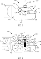
- FIG. 1 and 2 depicting a cutting tool 150 , in accordance with an embodiment of the present invention, in an assembled position and in an exploded view, respectively.
- the cutting tool 150 includes a cutting tool holder 100 and a cutting insert 152 , clamped therein.
- the cutting tool holder 100 has an internal continuous coolant passage 130 for providing tool coolant fluid C towards the cutting edge of the cutting insert 152 , clamped in the cutting tool holder 100 .
- the cutting tool holder 100 comprises a holder body 102 , an upper jaw 104 and a base jaw 106 .
- the upper and base jaws 104 , 106 define an insert receiving pocket 108 therebetween, located forward of the holder body 102 and having a longitudinal pocket axis B .
- the upper jaw 104 and the base jaw 106 are coupled with the holder body 102 .
- the upper jaw 104 and the base jaw 106 are formed in one-piece unitary construction with the holder body 102 .
- the upper jaw 104 has a front end 116 and a rearward end 118 .
- the upper jaw 104 and the base jaw 106 are spaced apart by a gap 125 , ending in a resilience recess 110 located adjacent the rearward end 118 of the upper jaw 104 .
- the resilience recess 110 is bounded by a resilience recess wall 112 extending along a resilience recess axis A , transversely to the pocket axis B .
- the resilience recess axis A may be perpendicular to the pocket axis B and may even intersect the latter.
- the resilience recess wall 112 may be substantially cylindrical. Alternatively, the resilience recess wall 112 may have any other shape.
- the gap 125 and the resilience recess 110 allow the upper jaw 104 to resiliently deflect towards the base jaw 106 , upon a vertical force applied thereon.
- the holder body 102 is coupled with a longitudinal tool shank 158 , extending rearwards from the basic body 102 .
- the holder body 102 may be formed in one-piece unitary construction with the tool shank 158 .
- the tool shank 158 may, in turn, be held in a machine shaft.
- FIG. 3 and 4 depicting a side view and a partially transparent side view of the cutting tool 150 of Figure 1 , respectively.
- the cutting tool 150 is viewed along the resilience recess axis A .
- a holder body coolant channel 114 passes through the holder body 102 , and has a holder body inlet 111 and a holder body outlet 113 .
- the holder body outlet 113 is located forward of the holder body inlet 111 .
- the holder body outlet 113 opens out to the resilience recess wall 112 (i.e., the holder body outlet 113 is in fluid communication with the resilience recess 110 ).
- the holder body inlet 111 opens out to a coolant source 156 , providing coolant fluid C into the holder body coolant channel 114 .
- the tool coolant source 156 may be, for example, a shank coolant channel 160 , formed longitudinally through the tool shank 158 , and opening out in the rear of the tool shank 158 .
- the orientation and the coupling of the holder body coolant channel 114 with the tool coolant source 156 shown in the drawings should be considered as an example only, and not binding in any way to the present invention.
- An upper jaw coolant channel 120 passes through the upper jaw 104 and has an upper jaw inlet 121 and an upper jaw outlet 123 .
- the upper jaw inlet 121 opens out to the resilience recess wall 112 , spaced apart from the holder body outlet 113 (i.e., the upper jaw inlet 121 is in fluid communication with the resilience recess 110 ).
- the upper jaw inlet 121 may be located diametrically opposite of the holder body outlet 113 .
- the upper jaw outlet 123 opens out to the front end 116 of the upper jaw 104 .
- a screw bore 124 extends vertically along a screw axis S , through the upper jaw 104 , crossing the gap 125 into the base jaw 106 .
- the screw axis S may be perpendicular to the pocket axis B .
- the screw axis S may be angled at an acute angle or an obtuse angle relative to the pocket axis B .
- the portion of the screw bore 124 extending into the base jaw 106 is a threaded bore portion 127 .
- the screw bore 124 may intersect with the upper jaw coolant channel 120 , as depicted in the Figure 4 .
- the cutting tool holder 100 may also include a fastening screw 122 , inserted into the screw bore 124 .
- the fastening screw 122 has a head portion 144 , a threading portion 148 , and a neck portion 146 extending therebetween.
- the neck portion 146 is narrower than the head portion 144 and the threading portion 148 .
- the neck portion 146 is also narrower than the screw bore 124 , in particular at the upper jaw coolant channel 120 .
- the threading portion 148 cooperates with the threaded bore portion 127 .
- the head portion 144 applies a vertical force on the upper jaw 104 , forcing it to deflect towards the base jaw 106 , and thus clamp the cutting insert 152 in the insert receiving pocket 108 .
- the neck portion 146 thereof is located in the upper jaw coolant channel 120 .
- the cutting tool holder 100 also includes a compressible tool coolant plug 126 , having a plug peripheral surface 142 .
- the plug peripheral surface 142 conforms to the shape of the resilience recess wall 112 , such that the coolant plug 126 would fit into the resilience recess 110 .
- the plug peripheral surface 142 may be substantially cylindrical, having two opposing plug end surface 140 between which the plug peripheral surface 142 extends.
- the plug peripheral surface 142 may have any other shape conforming to the shape of the resilience recess wall 112 .
- the plug peripheral surface 142 may have a conical shape, in which case only a single plug end surface 140 may be connected to the peripheral surface 142 .
- a plug coolant channel 128 passes through the coolant plug 126 , opening out to the plug peripheral surface 142 , at a plug inlet 131 and a plug outlet 133 .
- the tool coolant plug 126 is inserted into the resilience recess 110 , such that the plug inlet 131 faces the holder body outlet 113 , and the plug outlet 133 faces the upper jaw inlet 121 .
- the plug coolant channel 128 thus provides a fluid path from the holder body coolant channel 114 to the upper jaw coolant channel 120 , and forms part of the continuous coolant passage 130 from the coolant source 156 to the upper jaw outlet 123 .
- the tool coolant plug 126 is formed of a compressible material, such as a polymer (e.g., polyurethane, elastomer, and the like), allowing the tool coolant plug 126 to elastically compress under forces acting on the plug peripheral surface 142 .
- a compressible material such as a polymer (e.g., polyurethane, elastomer, and the like)
- the resilience recess wall 112 grips the plug peripheral surface 142 , and compresses the tool coolant plug 126 , thereby holding it in place.
- the diameter of the plug inlet 131 may be slightly larger than the diameter of the holder body outlet 113 , such that the holder body outlet 113 is covered by the plug inlet 131 .
- the diameter of the plug outlet 133 is slightly larger than the diameter of the upper jaw inlet 121.
- the tool coolant plug 126 Since the tool coolant plug 126 is formeds of a compressible material, it does not resist the resilient deflection of the upper jaw 104 towards the base jaw 106 . It is understood, however, that the extent of compression of the tool coolant plug 126 will be limited by the clamping of the cutting inset 152 with the underside of the upper jaw front end 116 . Therefore, the extent of travel of the front end 116 in clamping the cutting insert 152 is to be taken into account in determining the dimensions of the tool coolant plug 126 relative to the dimensions of the resilience recess 110 , along with the compressibility of the tool coolant plug 126 itself.
- the tool coolant plug 126 may further include two end plates, each attached to one of the plug end surfaces 140 .
- the end plates are made of a material harder than the material of the tool coolant plug 126 , for example, they are made of metal (e.g., aluminum or steel).
- the end plates cover at least a portion of the plug end surfaces 140 , inter alia, in order to protect the tool coolant plug 126 , for example, from piercing by metal chips removed from the machined work piece.
- the compressible material forming the tool coolant plug 126 is durable under typical metal machining temperatures at the resilience recess 110 , and rough chemical environment.
- a polymer e.g., polyurethane, elastomer, and the like
- polyurethane may sustain temperatures typically up to 125°C without changing its properties.
- the compressible material is durable under contact with the cutting tool coolant fluid C (e.g., tool coolant emulsion, usually comprising oils, solvents and the like), which may be chemically abrasive. Therefore, the coolant plug 126 is formed to withstand such metal machining conditions, i.e., typical temperatures and possibly chemically abrasive environment. Typical machining conditions may also include considerable friction, vibrations, and the like, and the tool coolant plug 126 is suitable for use in such conditions, as well.
- the compressible material forming the tool coolant plug 126 has a level of rebound resilience.
- the tool coolant plug 126 resiliently returns to assume its neutral position within the resilience recess 110 .
- the neck portion 146 of the fastening screw 122 is located in the upper jaw coolant channel 120 , and the neck portion 146 is narrower than the screw bore 124 at the upper jaw coolant channel 120 .
- Two sealing rings 138 are located on both sides of the neck portion 146 , having an outer diameter corresponding to the diameter of the screw bore 124 at the upper jaw coolant channel 120 .
- sealing rings 138 seal the screw bore 124 on both sides of the upper jaw coolant channel 120 , preventing the coolant fluid C from leaking out of the upper jaw coolant channel 120 .
- the sealing rings 138 may be located in sealing ring grooves, where a first sealing ring groove is formed between the neck portion 146 and the head portion 144 , and a second one is formed between the neck portion 146 and the threading portion 148 .
- the tool coolant plug 126 may further include a positioning member 132 , to determine the orientation of the tool coolant plug 126 , i.e., in order to make sure that the plug inlet 121 is aligned with the holder body outlet 113 , and the plug outlet 133 is aligned with the upper jaw inlet 121 .
- the resilience recess wall 112 has a positioning groove 134 formed therein, corresponding to the shape of the positioning member 132 .
- Figures 6 and 7 depict one embodiment of the tool coolant plug 126 , in a perspective view and a perspective transparent view, respectively.
- the positioning member 132 is in the form of a positioning pin 136 protruding out of the plug peripheral surface 142 , for fitting into the positioning groove 134 .
- the positioning pin 136 is located in a positioning pin bore 137 formed into the tool coolant plug 126 and opening out to the plug peripheral surface 142 .
- the positioning pin bore 137 extends substantially parallel to the plug coolant channel 128 .
- Figures 8 and 9 depict an alternative embodiment of the tool coolant plug 126 , in a perspective view and a perspective transparent view, respectively.
- the tool coolant plug 126 has a positioning protrusion 162 , extending out of the plug peripheral surface 142 .
- the positioning protrusion 162 may extend, for example, from one of the plug end surfaces 140 , towards the plug inlet 131 or the plug outlet 133 .
- the positioning protrusion 162 extends from the plug end surface 140 towards the plug inlet 131 , along the plug peripheral surface 142 , generally perpendicular to the direction of the plug coolant channel 128 .
- the positioning protrusion 162 may be formed in one-piece unitary construction with the plug peripheral surface 142 .
- the positioning member 132 e.g., either the positioning pin 136 or the positioning protrusion 162
- the tool coolant plug 126 may be inserted into the resilience recess 110 , only when the positioning member 132 slides into the positioning groove 134 , thereby determining the orientation of the tool coolant plug 126 relative to the resilience recess 110. In this manner, the orientation of the tool coolant plug 126 is maintained such that the plug inlet 131 faces the holder body outlet 113 , and the plug outlet 133 faces the upper jaw inlet 121 . This ensures formation of the fluid path from the holder body coolant channel 114 to the upper jaw coolant channel 120 .
- the positioning member 132 is confined within the positioning groove 134 , thus preventing the tool coolant plug 126 from rotating about the resilience recess axis A , relative to the resilience recess wall 112 .
- the positioning member 132 is also stopped against the inner surface of the positioning groove 134 , thus preventing the tool coolant plug 126 from moving further into the resilience recess 110 , and determining the location of the tool coolant plug 126 along the resilience recess axis A .
- the cutting insert 152 has at least one cutting edge 154 , to be employed for metal cutting and other metal machining procedures.
- the cutting insert 152 depicted in the drawings, is an indexable cutting insert with two cutting edges 154 .
- the upper jaw outlet 123 opens out in the direction of the cutting edge 154 .
- the coolant fluid C advances through the coolant passage 130 , it is sprayed out of the upper jaw outlet 123 , towards the cutting insert 152 , and in particular towards the cutting edge 154 .
- the coolant fluid C is required for cooling down the cutting edge 154 and the cutting area of the machined work piece.
- the tool coolant fluid C sprayed out towards the cutting edge 154 may be used for breaking or deflecting metal chips removed from the work piece.
- the cutting insert 152 may be any cutting insert suitable for clamping in a tool holder, such as in the insert receiving pocket 108 of the cutting tool holder 100 .
- the cutting insert 152 depicted in the accompanying drawings is a non-binding example for the cutting insert, and the particulars of the insert receiving pocket 108 are also a non-binding example for the insert receiving pocket. It will be understood that the insert receiving pocket 108 should be formed to be suitable for receiving any particular form of cutting insert.
- FIG. 5 depicting a top view of the cutting tool 150 of Figure 1 , viewed along the screw axis S .
- the cutting tool holder 100 is tapering, namely narrowing down from the direction of the tool shank 158 , towards the insert receiving pocket 108 (i.e., towards the front end 116 of the upper jaw 104 ).
- the tool holder 100 has two holder side surfaces 164 , extending along the sides of the holder body 102 and the upper and base jaws 104 , 106 .
- the holder side surfaces 164 When viewed along the screw axis S (i.e., in the top view) the holder side surfaces 164 form a taper angle ⁇ therebetween.
- the tapering of the cutting tool holder 100 means that the front end 116 is narrower than the holder body 102 , which leaves limited space for providing a passage for the cutting tool coolant C , such that would reach the cutting edge 154 from the upper jaw 104 (i.e., from above the cutting edge 154 ). Accordingly, there is typically insufficient space to form a coolant channel within the holder body 102 , located above the resilience recess 110 . Similarly, there is a limited possibility to install external coolant-providing members, for example on top of the upper jaw 104 , or along the holder side surfaces 164 , such that could spray coolant fluid from above the cutting edge 154 . Adding such external coolant providing members may limit or obstruct the operation of the cutting tool 150 , and is therefore undesirable.
- the cutting tool holder 100 in accordance with the present invention takes advantage of the resilience recess 110 , using it in the coolant passage 130 , for the coolant fluid C to advance from the holder body 102 towards the upper jaw 104 .
- This is achieved by the compressible tool coolant plug 126 , fitted into the resilience recess 110 , and forming part of the coolant passage 130 , without resisting the deflection of the upper jaw 104 .
- the upper jaw coolant channel 120 may intersect with the screw bore 124 (i.e., since there is insufficient space for the coolant passage 130 to be spaced apart from the screw bore 124 ). Still, the coolant fluid C is allowed to flow through the upper jaw coolant channel 120 , around the fastening screw 122 and across the screw bore 124 , towards the upper jaw outlet 123 , thereby also overcoming the limited space constraint.
Landscapes
- Engineering & Computer Science (AREA)
- Mechanical Engineering (AREA)
- Cutting Tools, Boring Holders, And Turrets (AREA)
- Auxiliary Devices For Machine Tools (AREA)
Priority Applications (1)
| Application Number | Priority Date | Filing Date | Title |
|---|---|---|---|
| PL13796167T PL2919933T3 (pl) | 2012-11-13 | 2013-10-20 | Uchwyt narzędzia skrawającego z wewnętrznym kanałem chłodziwa wyposażony w ściśliwy element |
Applications Claiming Priority (2)
| Application Number | Priority Date | Filing Date | Title |
|---|---|---|---|
| US13/675,233 US8985913B2 (en) | 2012-11-13 | 2012-11-13 | Cutting tool holder with internal coolant passage having a compressible member |
| PCT/IL2013/050842 WO2014076689A1 (en) | 2012-11-13 | 2013-10-20 | Cutting tool holder with internal coolant passage having a compressible member |
Publications (2)
| Publication Number | Publication Date |
|---|---|
| EP2919933A1 EP2919933A1 (en) | 2015-09-23 |
| EP2919933B1 true EP2919933B1 (en) | 2017-03-22 |
Family
ID=49674354
Family Applications (1)
| Application Number | Title | Priority Date | Filing Date |
|---|---|---|---|
| EP13796167.8A Active EP2919933B1 (en) | 2012-11-13 | 2013-10-20 | Cutting tool holder with internal coolant passage having a compressible member |
Country Status (13)
Families Citing this family (26)
| Publication number | Priority date | Publication date | Assignee | Title |
|---|---|---|---|---|
| DE102012004804C5 (de) | 2012-03-09 | 2019-03-14 | Kennametal Inc. | Stechschneidplatte sowie Stechschneidwerkzeug |
| EP2703104B1 (en) * | 2012-08-29 | 2015-07-08 | Sandvik Intellectual Property AB | Holder assembly for a cutting tool insert |
| SE1350795A1 (sv) * | 2013-06-28 | 2014-12-29 | Sandvik Intellectual Property | Verktyg för spånavskiljande bearbetning jämte skärhållande blad och bytbart skär härför. |
| US9579727B2 (en) * | 2014-05-28 | 2017-02-28 | Kennametal Inc. | Cutting assembly with cutting insert having enhanced coolant delivery |
| EP3023179B1 (de) * | 2014-11-18 | 2020-04-08 | Walter Ag | Stechklinge und Ein- und Abstechwerkzeug |
| DE102014116915A1 (de) * | 2014-11-19 | 2016-05-19 | Kennametal Inc. | Werkzeughalter für einen Schneideinsatz |
| DE102014119295B4 (de) * | 2014-12-19 | 2023-08-10 | Kennametal Inc. | Werkzeughalter für einen Schneideinsatz sowie Verfahren zur Herstellung des Werkzeughalters |
| WO2017018369A1 (ja) * | 2015-07-24 | 2017-02-02 | 京セラ株式会社 | 切削工具及びこれを用いた切削加工物の製造方法 |
| DE112016006041B4 (de) * | 2015-12-25 | 2024-05-16 | Kyocera Corporation | Halter für ein Schneidwerkzeug, Schneidwerkzeug und Verfahren zum Herstellen eines maschinell-bearbeiteten Produkts |
| EP3192600B1 (en) * | 2016-01-18 | 2022-03-09 | Sandvik Intellectual Property AB | Metal cutting tool holder comprising fluid passages |
| DE102016205658B3 (de) * | 2016-04-06 | 2017-09-07 | Gühring KG | Schneidwerkzeug mit einem an einem trägerkörper durch eine spannpratze lösbar befestigtem schneidkörper |
| US10052694B2 (en) * | 2016-05-04 | 2018-08-21 | Kennametal Inc. | Apparatus and method for cooling a cutting tool using super critical carbon dioxide |
| DE102016109327A1 (de) * | 2016-05-20 | 2017-11-23 | Hartmetall-Werkzeugfabrik Paul Horn Gmbh | Halter für ein Werkzeug zur spanenden Bearbeitung, insbesondere für ein Langdrehwerkzeug |
| CN106513727B (zh) * | 2016-12-28 | 2019-01-04 | 盐城工学院 | 一种内孔端槽切削工具 |
| KR101918535B1 (ko) * | 2017-05-16 | 2018-11-14 | 한국야금 주식회사 | 절삭 인서트 냉각 장치 |
| US10300532B2 (en) * | 2017-06-26 | 2019-05-28 | Kennametal Inc. | Clamp for tool holder |
| DE102017123786A1 (de) * | 2017-10-12 | 2019-04-18 | Hartmetall-Werkzeugfabrik Paul Horn Gmbh | Halter für ein Nutstoßwerkzeug |
| US10730115B2 (en) | 2017-11-29 | 2020-08-04 | Iscar, Ltd. | Cutting tool fastener having internal fluid channel and spherical head abutment surface |
| PT3575022T (pt) | 2018-05-29 | 2020-06-23 | Ceram Gmbh | Sistema de ferramentas |
| CN108818118B (zh) * | 2018-06-11 | 2021-02-19 | 瑞泰光学(常州)有限公司 | 激光辅助微加工系统及其温度控制方法 |
| AT16570U1 (de) * | 2018-08-01 | 2020-01-15 | Ceratizit Austria Gmbh | Drehwerkzeug-Halter |
| DE102019200692A1 (de) * | 2019-01-21 | 2020-07-23 | Gühring KG | Maschinenwerkzeug |
| US10857603B2 (en) * | 2019-03-19 | 2020-12-08 | Iscar, Ltd. | Insert holder having transversely oriented insert receiving pocket with upper stopper surface, cutting tool and cutting insert |
| CN113795344B (zh) * | 2019-05-13 | 2024-01-19 | 京瓷株式会社 | 夹紧构件、机床以及切削加工物的制造方法 |
| US11806793B2 (en) | 2021-11-03 | 2023-11-07 | Iscar, Ltd. | Cutting insert having laterally spaced apart, longitudinally extending wedge abutment surfaces, tool holder and cutting tool |
| US12275078B2 (en) | 2022-05-03 | 2025-04-15 | Iscar, Ltd. | Rotationally asymmetric double-ended grooving cutting insert, insert holder and cutting tool |
Family Cites Families (35)
| Publication number | Priority date | Publication date | Assignee | Title |
|---|---|---|---|---|
| US3323195A (en) * | 1967-01-18 | 1967-06-06 | Scienco Inc | Coolant adapter for tool holder |
| US3889520A (en) * | 1973-02-13 | 1975-06-17 | Theodor Stoferle | Fluidic system for monitoring machine tool wear during a machining operation |
| SU1127695A1 (ru) * | 1982-09-20 | 1984-12-07 | Нижнеднепровский Ордена Октябрьской Революции Трубопрокатный Завод Им.К.Либкнехта | Отрезной резец |
| US4621547A (en) * | 1983-02-28 | 1986-11-11 | Yankoff Gerald K | Method and apparatus for machining |
| US4848198A (en) | 1988-04-21 | 1989-07-18 | Kennametal Inc. | Chip breaking tool holder |
| IL97746A (en) * | 1991-04-02 | 1995-01-24 | Iscar Ltd | Metal cutting tool |
| IL99297A (en) * | 1991-08-26 | 1995-11-27 | Iscar Ltd | Sealing bushing for the shaft for a work piece |
| JPH0631502A (ja) | 1992-07-13 | 1994-02-08 | Genichi Sato | 切削工具 |
| JPH06126510A (ja) | 1992-10-15 | 1994-05-10 | Mitsubishi Materials Corp | 旋削工具 |
| FR2713117B1 (fr) * | 1993-12-01 | 1996-01-05 | Snecma | Procédé d'usinage de pièces en titane ou alliages de titane et bride d'arrossage pour un tel usinage. |
| JPH07237008A (ja) | 1994-02-28 | 1995-09-12 | Mitsubishi Materials Corp | 内部給液式切削工具 |
| JP3317783B2 (ja) * | 1994-07-08 | 2002-08-26 | 東芝タンガロイ株式会社 | 旋削工具 |
| IL115544A (en) * | 1995-10-06 | 1998-12-06 | Iscar Ltd | Cutting tool system with replaceable adapter |
| US6299388B1 (en) * | 2000-02-03 | 2001-10-09 | Slabe Machine Products Company | Universal tool holder collant delivery adapters |
| SE522930C2 (sv) * | 2001-04-24 | 2004-03-16 | Sandvik Ab | Skärverktyg för avsticknings- och spårstickningsändamål med en spännmekanism innefattande dragstång och spännskruv |
| US6652200B2 (en) * | 2001-11-01 | 2003-11-25 | Rolf H. Kraemer | Tool holder with coolant system |
| SE525462C2 (sv) * | 2002-06-18 | 2005-02-22 | Sandvik Ab | Verktygshuvud för spånavskiljande metallbearbetningsverktyg med spännskruv vilken ingängas i en mutterrulle |
| SE526767C2 (sv) * | 2003-10-16 | 2005-11-01 | Sandvik Intellectual Property | Skärverktyg med tillsatskropp med serrationsyta samt förfarande för tillverkning av skärverktyg |
| SE526536C2 (sv) * | 2003-11-19 | 2005-10-04 | Sandvik Intellectual Property | Verktygshuvud med spännanordning i form av en mutterrulle verkande i en slits |
| SE526894C2 (sv) | 2004-03-03 | 2005-11-15 | Sandvik Intellectual Property | Skärverktyg samt verktygshuvud med rörformig kylmedelskanal |
| US7273331B2 (en) * | 2004-12-29 | 2007-09-25 | Giannetti Enrico R | Boring bar having internal coolant supply |
| GB0501134D0 (en) * | 2005-01-20 | 2005-02-23 | Rolls Royce Plc | Cutting tool |
| US20070283794A1 (en) * | 2006-06-13 | 2007-12-13 | Giannetti Enrico R | Machine tool holder having internal coolant supply and cutter retaining and coolant distribution cutter insert retaining clamp assembly |
| SE530581C2 (sv) | 2006-11-28 | 2008-07-08 | Sandvik Intellectual Property | Verktyg och grundkropp för spånavskiljande innefattande två kanaler för en fluid |
| SE530579C2 (sv) * | 2006-11-28 | 2008-07-08 | Sandvik Intellectual Property | Verktyg och grundkropp för spånavskiljande bearbetning med flera kanaler |
| US7883299B2 (en) * | 2007-01-18 | 2011-02-08 | Kennametal Inc. | Metal cutting system for effective coolant delivery |
| JP5115148B2 (ja) * | 2007-10-30 | 2013-01-09 | 三菱マテリアル株式会社 | インサート着脱式切削工具のヘッド部材およびインサート着脱式切削工具 |
| JP5267173B2 (ja) | 2009-02-03 | 2013-08-21 | 三菱マテリアル株式会社 | インサート着脱式切削工具 |
| IL197095A (en) * | 2009-02-17 | 2013-02-28 | Iscar Ltd | Cutting tool having a retractable nozzle |
| US8734062B2 (en) * | 2010-09-02 | 2014-05-27 | Kennametal Inc. | Cutting insert assembly and components thereof |
| US8388268B2 (en) * | 2011-03-07 | 2013-03-05 | Kennametal Inc. | Cutting assembly |
| DE102011016148B4 (de) | 2011-03-28 | 2024-06-06 | Hartmetall-Werkzeugfabrik Paul Horn Gmbh | Werkzeug zur spanenden Bearbeitung eines Werkstücks mit seitlichem Kühlmittelaustritt und Halter für das Werkzeug |
| US8827598B2 (en) * | 2011-11-22 | 2014-09-09 | Kennametal Inc. | Cutting assembly with enhanced coolant delivery |
| US8696259B2 (en) * | 2012-02-02 | 2014-04-15 | Iscar, Ltd. | Tool holder having set screw for clamping a cutting insert therein |
| EP2703104B1 (en) * | 2012-08-29 | 2015-07-08 | Sandvik Intellectual Property AB | Holder assembly for a cutting tool insert |
-
2012
- 2012-11-13 US US13/675,233 patent/US8985913B2/en active Active
-
2013
- 2013-10-20 CA CA2891292A patent/CA2891292C/en active Active
- 2013-10-20 PT PT137961678T patent/PT2919933T/pt unknown
- 2013-10-20 EP EP13796167.8A patent/EP2919933B1/en active Active
- 2013-10-20 JP JP2015541297A patent/JP6200960B2/ja active Active
- 2013-10-20 RU RU2015122734A patent/RU2633201C2/ru active
- 2013-10-20 WO PCT/IL2013/050842 patent/WO2014076689A1/en active Application Filing
- 2013-10-20 ES ES13796167.8T patent/ES2627260T3/es active Active
- 2013-10-20 CN CN201380059062.3A patent/CN104768682B/zh active Active
- 2013-10-20 PL PL13796167T patent/PL2919933T3/pl unknown
- 2013-10-20 KR KR1020157011829A patent/KR101795193B1/ko active Active
- 2013-10-20 BR BR112015010596-3A patent/BR112015010596B1/pt active IP Right Grant
-
2015
- 2015-05-11 IL IL238751A patent/IL238751B/en active IP Right Grant
Non-Patent Citations (1)
| Title |
|---|
| None * |
Also Published As
| Publication number | Publication date |
|---|---|
| BR112015010596B1 (pt) | 2020-10-27 |
| PT2919933T (pt) | 2017-05-02 |
| KR20150082286A (ko) | 2015-07-15 |
| IL238751B (en) | 2018-01-31 |
| JP2015533665A (ja) | 2015-11-26 |
| CN104768682B (zh) | 2017-06-27 |
| WO2014076689A1 (en) | 2014-05-22 |
| RU2015122734A (ru) | 2017-01-10 |
| US8985913B2 (en) | 2015-03-24 |
| PL2919933T3 (pl) | 2017-07-31 |
| US20140133924A1 (en) | 2014-05-15 |
| KR101795193B1 (ko) | 2017-11-07 |
| CA2891292C (en) | 2018-02-13 |
| RU2633201C2 (ru) | 2017-10-11 |
| CN104768682A (zh) | 2015-07-08 |
| IL238751A0 (en) | 2015-06-30 |
| BR112015010596A2 (pt) | 2017-07-11 |
| JP6200960B2 (ja) | 2017-09-20 |
| CA2891292A1 (en) | 2014-05-22 |
| ES2627260T3 (es) | 2017-07-27 |
| EP2919933A1 (en) | 2015-09-23 |
Similar Documents
| Publication | Publication Date | Title |
|---|---|---|
| EP2919933B1 (en) | Cutting tool holder with internal coolant passage having a compressible member | |
| KR102205812B1 (ko) | 절삭 공구의 냉각 시스템을 위한 커플링 및 블레이드 | |
| JP6616939B2 (ja) | 溝入れ工具ホルダー用カートリッジ、対応する溝入れ工具ホルダー、キット及びこれらのアセンブリ | |
| EP2398613B1 (en) | Cutting tool and cutting insert with fluid flow structures | |
| CN102317013B (zh) | 具有可缩回喷嘴的切削工具 | |
| RU2617466C2 (ru) | Отрезная пластина и держатель пластины, выполненные с возможностью подачи охлаждающей жидкости под давлением | |
| US7273331B2 (en) | Boring bar having internal coolant supply | |
| US9095913B2 (en) | Cutting inserts | |
| CN102672213A (zh) | 切削组件 | |
| JP7157086B2 (ja) | 分割用の刃を収容するための保持部 | |
| US20150196959A1 (en) | Cutting tool with wedge clamping system | |
| US10010953B2 (en) | Wedge clamp and insert cartridge for cutting tool | |
| CA3056994A1 (en) | Cutting insert having two peripheral abutment ridges and cutting tool | |
| EP0636442B1 (en) | A metal cutting tool | |
| HK1004203A (en) | A metal cutting tool |
Legal Events
| Date | Code | Title | Description |
|---|---|---|---|
| PUAI | Public reference made under article 153(3) epc to a published international application that has entered the european phase |
Free format text: ORIGINAL CODE: 0009012 |
|
| 17P | Request for examination filed |
Effective date: 20150611 |
|
| AK | Designated contracting states |
Kind code of ref document: A1 Designated state(s): AL AT BE BG CH CY CZ DE DK EE ES FI FR GB GR HR HU IE IS IT LI LT LU LV MC MK MT NL NO PL PT RO RS SE SI SK SM TR |
|
| AX | Request for extension of the european patent |
Extension state: BA ME |
|
| DAX | Request for extension of the european patent (deleted) | ||
| GRAP | Despatch of communication of intention to grant a patent |
Free format text: ORIGINAL CODE: EPIDOSNIGR1 |
|
| INTG | Intention to grant announced |
Effective date: 20160623 |
|
| INTG | Intention to grant announced |
Effective date: 20160623 |
|
| GRAJ | Information related to disapproval of communication of intention to grant by the applicant or resumption of examination proceedings by the epo deleted |
Free format text: ORIGINAL CODE: EPIDOSDIGR1 |
|
| GRAP | Despatch of communication of intention to grant a patent |
Free format text: ORIGINAL CODE: EPIDOSNIGR1 |
|
| INTC | Intention to grant announced (deleted) | ||
| INTG | Intention to grant announced |
Effective date: 20161013 |
|
| GRAS | Grant fee paid |
Free format text: ORIGINAL CODE: EPIDOSNIGR3 |
|
| GRAA | (expected) grant |
Free format text: ORIGINAL CODE: 0009210 |
|
| AK | Designated contracting states |
Kind code of ref document: B1 Designated state(s): AL AT BE BG CH CY CZ DE DK EE ES FI FR GB GR HR HU IE IS IT LI LT LU LV MC MK MT NL NO PL PT RO RS SE SI SK SM TR |
|
| REG | Reference to a national code |
Ref country code: GB Ref legal event code: FG4D |
|
| REG | Reference to a national code |
Ref country code: CH Ref legal event code: EP |
|
| REG | Reference to a national code |
Ref country code: AT Ref legal event code: REF Ref document number: 877213 Country of ref document: AT Kind code of ref document: T Effective date: 20170415 |
|
| REG | Reference to a national code |
Ref country code: IE Ref legal event code: FG4D |
|
| REG | Reference to a national code |
Ref country code: PT Ref legal event code: SC4A Ref document number: 2919933 Country of ref document: PT Date of ref document: 20170502 Kind code of ref document: T Free format text: AVAILABILITY OF NATIONAL TRANSLATION Effective date: 20170421 |
|
| REG | Reference to a national code |
Ref country code: DE Ref legal event code: R096 Ref document number: 602013018959 Country of ref document: DE |
|
| REG | Reference to a national code |
Ref country code: SE Ref legal event code: TRGR |
|
| REG | Reference to a national code |
Ref country code: NL Ref legal event code: MP Effective date: 20170322 |
|
| REG | Reference to a national code |
Ref country code: ES Ref legal event code: FG2A Ref document number: 2627260 Country of ref document: ES Kind code of ref document: T3 Effective date: 20170727 |
|
| PG25 | Lapsed in a contracting state [announced via postgrant information from national office to epo] |
Ref country code: LT Free format text: LAPSE BECAUSE OF FAILURE TO SUBMIT A TRANSLATION OF THE DESCRIPTION OR TO PAY THE FEE WITHIN THE PRESCRIBED TIME-LIMIT Effective date: 20170322 Ref country code: FI Free format text: LAPSE BECAUSE OF FAILURE TO SUBMIT A TRANSLATION OF THE DESCRIPTION OR TO PAY THE FEE WITHIN THE PRESCRIBED TIME-LIMIT Effective date: 20170322 Ref country code: HR Free format text: LAPSE BECAUSE OF FAILURE TO SUBMIT A TRANSLATION OF THE DESCRIPTION OR TO PAY THE FEE WITHIN THE PRESCRIBED TIME-LIMIT Effective date: 20170322 Ref country code: NO Free format text: LAPSE BECAUSE OF FAILURE TO SUBMIT A TRANSLATION OF THE DESCRIPTION OR TO PAY THE FEE WITHIN THE PRESCRIBED TIME-LIMIT Effective date: 20170622 Ref country code: GR Free format text: LAPSE BECAUSE OF FAILURE TO SUBMIT A TRANSLATION OF THE DESCRIPTION OR TO PAY THE FEE WITHIN THE PRESCRIBED TIME-LIMIT Effective date: 20170623 |
|
| REG | Reference to a national code |
Ref country code: LT Ref legal event code: MG4D |
|
| PG25 | Lapsed in a contracting state [announced via postgrant information from national office to epo] |
Ref country code: LV Free format text: LAPSE BECAUSE OF FAILURE TO SUBMIT A TRANSLATION OF THE DESCRIPTION OR TO PAY THE FEE WITHIN THE PRESCRIBED TIME-LIMIT Effective date: 20170322 Ref country code: BG Free format text: LAPSE BECAUSE OF FAILURE TO SUBMIT A TRANSLATION OF THE DESCRIPTION OR TO PAY THE FEE WITHIN THE PRESCRIBED TIME-LIMIT Effective date: 20170622 Ref country code: RS Free format text: LAPSE BECAUSE OF FAILURE TO SUBMIT A TRANSLATION OF THE DESCRIPTION OR TO PAY THE FEE WITHIN THE PRESCRIBED TIME-LIMIT Effective date: 20170322 |
|
| REG | Reference to a national code |
Ref country code: FR Ref legal event code: PLFP Year of fee payment: 5 |
|
| PG25 | Lapsed in a contracting state [announced via postgrant information from national office to epo] |
Ref country code: NL Free format text: LAPSE BECAUSE OF FAILURE TO SUBMIT A TRANSLATION OF THE DESCRIPTION OR TO PAY THE FEE WITHIN THE PRESCRIBED TIME-LIMIT Effective date: 20170322 |
|
| PG25 | Lapsed in a contracting state [announced via postgrant information from national office to epo] |
Ref country code: EE Free format text: LAPSE BECAUSE OF FAILURE TO SUBMIT A TRANSLATION OF THE DESCRIPTION OR TO PAY THE FEE WITHIN THE PRESCRIBED TIME-LIMIT Effective date: 20170322 Ref country code: SK Free format text: LAPSE BECAUSE OF FAILURE TO SUBMIT A TRANSLATION OF THE DESCRIPTION OR TO PAY THE FEE WITHIN THE PRESCRIBED TIME-LIMIT Effective date: 20170322 Ref country code: RO Free format text: LAPSE BECAUSE OF FAILURE TO SUBMIT A TRANSLATION OF THE DESCRIPTION OR TO PAY THE FEE WITHIN THE PRESCRIBED TIME-LIMIT Effective date: 20170322 |
|
| PG25 | Lapsed in a contracting state [announced via postgrant information from national office to epo] |
Ref country code: IS Free format text: LAPSE BECAUSE OF FAILURE TO SUBMIT A TRANSLATION OF THE DESCRIPTION OR TO PAY THE FEE WITHIN THE PRESCRIBED TIME-LIMIT Effective date: 20170722 Ref country code: SM Free format text: LAPSE BECAUSE OF FAILURE TO SUBMIT A TRANSLATION OF THE DESCRIPTION OR TO PAY THE FEE WITHIN THE PRESCRIBED TIME-LIMIT Effective date: 20170322 |
|
| REG | Reference to a national code |
Ref country code: DE Ref legal event code: R097 Ref document number: 602013018959 Country of ref document: DE |
|
| PLBE | No opposition filed within time limit |
Free format text: ORIGINAL CODE: 0009261 |
|
| STAA | Information on the status of an ep patent application or granted ep patent |
Free format text: STATUS: NO OPPOSITION FILED WITHIN TIME LIMIT |
|
| PG25 | Lapsed in a contracting state [announced via postgrant information from national office to epo] |
Ref country code: DK Free format text: LAPSE BECAUSE OF FAILURE TO SUBMIT A TRANSLATION OF THE DESCRIPTION OR TO PAY THE FEE WITHIN THE PRESCRIBED TIME-LIMIT Effective date: 20170322 |
|
| 26N | No opposition filed |
Effective date: 20180102 |
|
| PG25 | Lapsed in a contracting state [announced via postgrant information from national office to epo] |
Ref country code: SI Free format text: LAPSE BECAUSE OF FAILURE TO SUBMIT A TRANSLATION OF THE DESCRIPTION OR TO PAY THE FEE WITHIN THE PRESCRIBED TIME-LIMIT Effective date: 20170322 |
|
| PG25 | Lapsed in a contracting state [announced via postgrant information from national office to epo] |
Ref country code: MC Free format text: LAPSE BECAUSE OF FAILURE TO SUBMIT A TRANSLATION OF THE DESCRIPTION OR TO PAY THE FEE WITHIN THE PRESCRIBED TIME-LIMIT Effective date: 20170322 |
|
| REG | Reference to a national code |
Ref country code: CH Ref legal event code: PL |
|
| REG | Reference to a national code |
Ref country code: IE Ref legal event code: MM4A |
|
| PG25 | Lapsed in a contracting state [announced via postgrant information from national office to epo] |
Ref country code: LU Free format text: LAPSE BECAUSE OF NON-PAYMENT OF DUE FEES Effective date: 20171020 Ref country code: CH Free format text: LAPSE BECAUSE OF NON-PAYMENT OF DUE FEES Effective date: 20171031 Ref country code: LI Free format text: LAPSE BECAUSE OF NON-PAYMENT OF DUE FEES Effective date: 20171031 |
|
| REG | Reference to a national code |
Ref country code: BE Ref legal event code: MM Effective date: 20171031 |
|
| PG25 | Lapsed in a contracting state [announced via postgrant information from national office to epo] |
Ref country code: BE Free format text: LAPSE BECAUSE OF NON-PAYMENT OF DUE FEES Effective date: 20171031 |
|
| REG | Reference to a national code |
Ref country code: FR Ref legal event code: PLFP Year of fee payment: 6 |
|
| PG25 | Lapsed in a contracting state [announced via postgrant information from national office to epo] |
Ref country code: MT Free format text: LAPSE BECAUSE OF NON-PAYMENT OF DUE FEES Effective date: 20171020 |
|
| PG25 | Lapsed in a contracting state [announced via postgrant information from national office to epo] |
Ref country code: IE Free format text: LAPSE BECAUSE OF NON-PAYMENT OF DUE FEES Effective date: 20171020 |
|
| REG | Reference to a national code |
Ref country code: AT Ref legal event code: UEP Ref document number: 877213 Country of ref document: AT Kind code of ref document: T Effective date: 20170322 |
|
| PG25 | Lapsed in a contracting state [announced via postgrant information from national office to epo] |
Ref country code: HU Free format text: LAPSE BECAUSE OF FAILURE TO SUBMIT A TRANSLATION OF THE DESCRIPTION OR TO PAY THE FEE WITHIN THE PRESCRIBED TIME-LIMIT; INVALID AB INITIO Effective date: 20131020 |
|
| PG25 | Lapsed in a contracting state [announced via postgrant information from national office to epo] |
Ref country code: CY Free format text: LAPSE BECAUSE OF FAILURE TO SUBMIT A TRANSLATION OF THE DESCRIPTION OR TO PAY THE FEE WITHIN THE PRESCRIBED TIME-LIMIT Effective date: 20170322 |
|
| PG25 | Lapsed in a contracting state [announced via postgrant information from national office to epo] |
Ref country code: MK Free format text: LAPSE BECAUSE OF FAILURE TO SUBMIT A TRANSLATION OF THE DESCRIPTION OR TO PAY THE FEE WITHIN THE PRESCRIBED TIME-LIMIT Effective date: 20170322 |
|
| PG25 | Lapsed in a contracting state [announced via postgrant information from national office to epo] |
Ref country code: AL Free format text: LAPSE BECAUSE OF FAILURE TO SUBMIT A TRANSLATION OF THE DESCRIPTION OR TO PAY THE FEE WITHIN THE PRESCRIBED TIME-LIMIT Effective date: 20170322 |
|
| P01 | Opt-out of the competence of the unified patent court (upc) registered |
Effective date: 20230426 |
|
| PGFP | Annual fee paid to national office [announced via postgrant information from national office to epo] |
Ref country code: GB Payment date: 20240905 Year of fee payment: 12 Ref country code: PT Payment date: 20240819 Year of fee payment: 12 |
|
| PGFP | Annual fee paid to national office [announced via postgrant information from national office to epo] |
Ref country code: FR Payment date: 20240906 Year of fee payment: 12 |
|
| PGFP | Annual fee paid to national office [announced via postgrant information from national office to epo] |
Ref country code: CZ Payment date: 20240819 Year of fee payment: 12 |
|
| PGFP | Annual fee paid to national office [announced via postgrant information from national office to epo] |
Ref country code: PL Payment date: 20240809 Year of fee payment: 12 |
|
| PGFP | Annual fee paid to national office [announced via postgrant information from national office to epo] |
Ref country code: SE Payment date: 20240909 Year of fee payment: 12 Ref country code: IT Payment date: 20240808 Year of fee payment: 12 |
|
| PGFP | Annual fee paid to national office [announced via postgrant information from national office to epo] |
Ref country code: TR Payment date: 20240812 Year of fee payment: 12 |
|
| PGFP | Annual fee paid to national office [announced via postgrant information from national office to epo] |
Ref country code: DE Payment date: 20240905 Year of fee payment: 12 |
|
| PGFP | Annual fee paid to national office [announced via postgrant information from national office to epo] |
Ref country code: AT Payment date: 20240905 Year of fee payment: 12 |
|
| PGFP | Annual fee paid to national office [announced via postgrant information from national office to epo] |
Ref country code: ES Payment date: 20241204 Year of fee payment: 12 |