EP2919615B1 - Tuftformungsvorrichtung - Google Patents
Tuftformungsvorrichtung Download PDFInfo
- Publication number
- EP2919615B1 EP2919615B1 EP13801695.1A EP13801695A EP2919615B1 EP 2919615 B1 EP2919615 B1 EP 2919615B1 EP 13801695 A EP13801695 A EP 13801695A EP 2919615 B1 EP2919615 B1 EP 2919615B1
- Authority
- EP
- European Patent Office
- Prior art keywords
- skein
- support
- clamp
- fibres
- tuft
- Prior art date
- Legal status (The legal status is an assumption and is not a legal conclusion. Google has not performed a legal analysis and makes no representation as to the accuracy of the status listed.)
- Active
Links
Images

Classifications
-
- A—HUMAN NECESSITIES
- A46—BRUSHWARE
- A46B—BRUSHES
- A46B3/00—Brushes characterised by the way in which the bristles are fixed or joined in or on the brush body or carrier
- A46B3/02—Brushes characterised by the way in which the bristles are fixed or joined in or on the brush body or carrier by pitch, resin, cement, or other adhesives
-
- F—MECHANICAL ENGINEERING; LIGHTING; HEATING; WEAPONS; BLASTING
- F16—ENGINEERING ELEMENTS AND UNITS; GENERAL MEASURES FOR PRODUCING AND MAINTAINING EFFECTIVE FUNCTIONING OF MACHINES OR INSTALLATIONS; THERMAL INSULATION IN GENERAL
- F16J—PISTONS; CYLINDERS; SEALINGS
- F16J15/00—Sealings
- F16J15/16—Sealings between relatively-moving surfaces
- F16J15/32—Sealings between relatively-moving surfaces with elastic sealings, e.g. O-rings
- F16J15/3284—Sealings between relatively-moving surfaces with elastic sealings, e.g. O-rings characterised by their structure; Selection of materials
- F16J15/3288—Filamentary structures, e.g. brush seals
-
- A—HUMAN NECESSITIES
- A46—BRUSHWARE
- A46D—MANUFACTURE OF BRUSHES
- A46D1/00—Bristles; Selection of materials for bristles
- A46D1/08—Preparing uniform tufts of bristles
-
- A—HUMAN NECESSITIES
- A46—BRUSHWARE
- A46D—MANUFACTURE OF BRUSHES
- A46D1/00—Bristles; Selection of materials for bristles
- A46D1/04—Preparing bristles
-
- A—HUMAN NECESSITIES
- A46—BRUSHWARE
- A46D—MANUFACTURE OF BRUSHES
- A46D1/00—Bristles; Selection of materials for bristles
- A46D1/04—Preparing bristles
- A46D1/06—Machines or apparatus for cutting bristles
-
- A—HUMAN NECESSITIES
- A46—BRUSHWARE
- A46D—MANUFACTURE OF BRUSHES
- A46D3/00—Preparing, i.e. Manufacturing brush bodies
- A46D3/04—Machines for inserting or fixing bristles in bodies
-
- A—HUMAN NECESSITIES
- A46—BRUSHWARE
- A46D—MANUFACTURE OF BRUSHES
- A46D3/00—Preparing, i.e. Manufacturing brush bodies
- A46D3/04—Machines for inserting or fixing bristles in bodies
- A46D3/045—Machines for inserting or fixing bristles in bodies for fixing bristles by fusing or gluing to a body
-
- A—HUMAN NECESSITIES
- A46—BRUSHWARE
- A46D—MANUFACTURE OF BRUSHES
- A46D3/00—Preparing, i.e. Manufacturing brush bodies
- A46D3/08—Parts of brush-making machines
-
- F—MECHANICAL ENGINEERING; LIGHTING; HEATING; WEAPONS; BLASTING
- F16—ENGINEERING ELEMENTS AND UNITS; GENERAL MEASURES FOR PRODUCING AND MAINTAINING EFFECTIVE FUNCTIONING OF MACHINES OR INSTALLATIONS; THERMAL INSULATION IN GENERAL
- F16J—PISTONS; CYLINDERS; SEALINGS
- F16J15/00—Sealings
- F16J15/16—Sealings between relatively-moving surfaces
- F16J15/32—Sealings between relatively-moving surfaces with elastic sealings, e.g. O-rings
- F16J15/3284—Sealings between relatively-moving surfaces with elastic sealings, e.g. O-rings characterised by their structure; Selection of materials
Definitions
- This invention relates to apparatus for forming bristle tufts for use in a brush seal.
- Brush seals incorporate a large number of bristles (which comprise aligned wires or fibres) which are generally held at one end and free at the other.
- One known method of manufacture of such brush seals is to produce a tuft (or bundle) comprising a known number of bristles which are temporarily held together by some means. During subsequent manufacturing processes the individual tufts are placed between the front and back plates to form a brush seal. Once the brush seal has been assembled the temporary means of holding the tufts together is removed by an appropriate method to provide a uniform brush seal with a known number of bristles.
- the tools for holding or producing the bristle carrier on the one hand and the clamping devices for the bristles on the other are moved on closed paths; and, the clamping devices at at least one common station are transferred to the path of the tools and at least during the thermal processes are jointly moved with the tools and are subsequently returned to their movement path.
- US5183197 describes a method for the production of brush seals, by first forming a linear array of contiguous, parallelly aligned brush elements.
- the elements, each containing a multitude of bristles, are aligned in a resilient, linear support, in which the long axis of the bristles are parallel to each other.
- the resultant, resiliently supported array of brush elements is easily contoured to various arcuate shapes.
- the linear array is contoured in the form of a circular array, in which the free ends of the bristles in the array are joined to an annular backing ring.
- US5165758 describes a long ribbon, composed of a multitude of fine wires, placed at the requisite bristle angle onto a backing ring.
- a torch welds the ribbon to the backing plate and simultaneously severs the ribbon, thus forming a first bundle of wires.
- the severed ribbon is repositioned, relative to the backing ring, adjacent to the first bundle, and the ribbon is again welded in-place and cut. The procedure of placement, welding and cutting is repeated until the backing plate (or the ribbon) has been repositioned over the desired length of the plate to achieve the requisite bristle array of the brush seal.
- US4274575 describes a method of manufacturing a brush seal for effecting a seal between relatively moving parts.
- Brush elements are first made by assembling bundles of bristle elements in holding tubes.
- the brush elements are then mounted for instance by an adhesive on a carrier, so as to lie at the required disposition.
- the free end portions of the bristle elements are affixed to a brush seal root member, and the bristle elements are cut off at the required position between the root member and the carrier; the carrier and holding tubes (which may be re-used) are removed to leave the brush seal.
- a final machining of the brush seal, such as of the bristles, may be performed.
- GB2201336 describes a paintbrush in which the painting head is constructed from a number of pre-cut and glued bundles of drawn glass or quartz fibres. These bundles are prepared from a bulk reel of glass roving utilising an apparatus which automatically and continuously applies glue to and cuts the roving at desired intervals. These bundles may then either be combined using conventional techniques for paintbrush manufacture, or may be combined to construct a novel brush which may be cut back when worn to expose a new brush of smaller cross sectional area.
- the present invention provides an alternative apparatus for forming multi-filament tufts.
- the present invention consists in apparatus for forming multi-filament tufts for use in a brush seal including:
- embodiments of the invention are arranged to provide a tuft where the wires or fibres are held at one end and free at the other. This is advantageous over existing manufacturing methods where the bristles are typically held together along their entire length.
- Embodiments of the invention provide an improved automated method of manufacture and provide improved tuft filament retention. Thus, embodiments of the invention may reduce or obviating the reliance upon the presence of a skilled operator.
- skein in this specification refers to a multi-filament length of wires and fibres in which the wires or fibres are aligned.
- the cutter may be for cutting the skein before, after or during adhering.
- the cutter may typically be arranged to cut the skein to the required length while the skein is held stationary by the support.
- the support may be fixed and the reservoir may be movable relative to the support. This is advantageous in that it enables the apparatus to align, support, grip and form the end of a stationery skein of wires prior to them being bonded together in a controlled and repeatable way by immersion into an aligned and movable adhesive reservoir/reservoir guide. Excess adhesive may be wiped from the skein on retraction of the reservoir/support. For example, excess adhesive may be wiped from the skein by the aperture of the reservoir.
- the support may comprise a clamp.
- The, or each, clamp may be arranged to grip the skein.
- the clamp may be provided by opposed jaws.
- the jaws may be arranged to be relatively movable in a direction which is substantially perpendicular to the longitudinal axis of the skein.
- One or both jaws may be provided with a notch arranged to receive and align the skein. In the closed position, the notch or notches may define an aperture in which the skein is held.
- the jaws may be arranged to overlap in the closed position and may, for example, be provided with interlocking profiles.
- the support may comprise a plurality of clamps. Each clamp may define a different aperture in the closed position. For example, a first clamp may be arranged to generally gather the filaments of the skein into close alignment and a second clamp may be arranged to clamp the filaments to a desired cross-sectional size and/or shape.
- One or more radiant lamps may be provided for curing the adhesive applied to the end.
- the radiant lamps may be provided on the apparatus and may, for example be provided on the support.
- the apparatus may further include a mechanism for advancing the skein of parallel wires or fibres to the support.
- the apparatus may include a mechanism for advancing the skein along its axis.
- Control means may be provided for intermittently advancing the skein after each formed tuft is released by the support.
- the cutter may be movable along the longitudinal axis of the skein. As such, the length of the cut tuft may be adjustable.
- the cutter may also be movable vertically and horizontally to facilitate optimum cutter to skein alignment.
- the invention includes a tuft manufactured by the apparatus.
- the wires may be metal.
- the fibres may be any non-metallic fibres including carbon fibres.
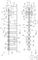
- a tuft forming apparatus is generally indicated at 10. It comprises a base plate 11, an advancing mechanism generally indicated at 12, a cutter mechanism 13, a support 14 and a glue head 15. Elements 12 to 15 are spaced along a path for a skein 16. The elements 12 to 15 are generally aligned about a common axis along which the skein is retained in use. In particular, the skein engaging portions of the advancing mechanism 12, support 14, glue head 15 are concentric about said common axis.
- the skein is typically formed from a plurality of aligned filaments, the particular material being selected in accordance with the environment in which the particular brush seal is intended to be used. It could equally be formed of aligned fibres or yarns of non-metallic materials such as carbon fibre. In general the wires or fibres will be parallel. Individual wires or fibres are designated 17 but it will be appreciated that in the practical embodiment there would be a significant number of wires per tuft.
- the advancing mechanism 12 comprises guide supports 18 and gripper heads 19.
- the gripper heads 19 have jaws, generally indicated at 20 that can grip and release the scheme 16.
- the gripper heads 19a, 19b are movable relative to the guide supports 18a, 18b, and 18c.
- the gripper heads 19a, 19b may be connected to a parallel slide gripper table 30 to actuate the movement of the gripper heads 19 in unison.
- the gripper heads may be arranged to engage the skein by closing the gripper jaws 20 before translating to advance the skein 16 in a direction towards the glue head 15.
- the gripper jaws 20 release the skein 16 at the end of their translation before the gripper heads 19a and 19b return to their original position, during which movement the skein 16 is supported by the guide supports 18.
- a fixed gripper 25 is also provided which grip the skein after the translation of gripper heads 20 so as to prevent any unintended reverse movement of the skein 16 while the gripper heads return to their start position.
- the skein 16 may be engaged by the support 14.
- the translation of the gripper heads 19 may be arranged such that a single movement of the heads translates the skein by the distance required to form a single tuft.
- the gripper heads 19a and 19b may be relatively movable along the path so that, for example, jaws 20a of gripper head 19a shut and the jaws 20b of the gripper head 19b open the gripper head 19a can be traversed from left to right advancing the skein 16 through the open jaws 20b of the gripper head 19b. Those jaws 20b then close and the jaws 20a of gripper head 19a open for it to return to its initial position. In this way the skein 16 is advanced by the distance between the gripper heads 19a, 19b. This will conveniently be approximately the length of the intended tuft.
- the guide supports 18 may optionally be omitted in such an arrangement.
- the cutter mechanism 13 can in its most simple form be a pair of mechanical scissors but it could be a laser or other appropriate cutting device. Somewhat surprisingly, the applicants have found that a mechanical cutting mechanism is most effective avoiding any undesirable welding of individual fibres in the tuft .As will be explained below, the cutter 13 cuts the skein 16 at an appropriate moment to cut the wires 17 to length for the tuft.
- the cutter mechanism 13 may be relatively movable with respect to the support 14 to enable the tuft length to be adjusted.
- This may allow the tuft length to be adjusted without the need to move the skein 16 (which may reduce the chance of misalignment of the fibres).
- An alignment block 42 may be provided proximal to the cutter mechanism 13 to support and/or align the skein 16 at the cutting location.
- the block 42 is provided with an aperture 44 through which the skein 16 is threaded.
- the block may also be provided with a slot 46 for receiving an insert (not shown).
- the insert is provided with an aperture which is aligned with (and typically coaxial with) the aperture 44 when positioned within the slot 46.
- the slot and insert may be used to quickly reconfigure the alignment block 42 to receive different sized and/or shaped skeins 16.
- the advanced skein 16 moves into openable and closable jaws of the support 14 whereby the end 21 of the skein 16 projects to the right hand side of the support 14.
- the support 14 may be provided with a multi stage clamping arrangement for holding the skein 16.
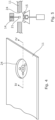
- a first clamp 32 may be provided to gather together and retain the fibres of the skein while a second shape clamp 34 may be arranged to more tightly form the skein 16 into the desired cross-sectional size and/or shape of tuft prior to the gluing of the skein end 21.
- Both clamp 32 and shape clamp 34 are provided with end profiles which are arranged to engage the skein.
- the end profiles comprise opposed pairs of notches 39 and 40, 37 and 38 which in the closed position form an aperture within which the skein 16 will be retained.
- the aperture formed by the notches 39 and 40 of the clamp 32 is preferably of a larger diameter than that formed by the notches 37 and 38 of the shape clamp 34.
- the interlocking features of the clamp 32 comprise a tab 42 on a first clamp member 32a and a complementary recess 41 in the opposing clamp member 32b.
- the shape clamp 34 is provided with interlocking features in the form of stepped opposing recesses 35 and 36 on the respective clamp numbers 34a and 34b such that, in the closed position, the jaws may overlap (in the manner of a lap joint).
- the clamp 32 is arranged to lead the shape clamp 34 such that its ends meet the skein 16 before those of the shape clamp 34.
- the clamp 32 and shape clamp 36 are actuated by a common actuation mechanism and the ends of the clamp 32 may be resilient such that they can be compressed after closing to allow for subsequent movement of the actuation mechanism to close the shape clamp 34.
- the clamp 32 may be mounted via a spring to the actuation mechanism.
- the glue head 15 has an open ended adhesive reservoir 22 facing the end 21 and aligned therewith for receiving the end 21. This can be achieved by either moving the support 14 or the glue head 15 or both. In the plan view, the glue head 15 has moved into an adhering position as indicated in broken line in which the end 21 lies in the reservoir 22 and becomes coated with adhesive. If the support 14 is to move, then the skein 16 would need to be cut prior to that movement and the support 14 would have to move from right to left to pick up the skein again. Alternatively both jaws 20 could be opened allowing the skein to be pulled through, in which case gripper heads 18 and 19 could be spaced nearer together.
- the jaws of the clamps 32 and 34 of the support 14 release the tuft such that it falls into a locating cradle 49 which may for example be provided with a recess 49, for example a v-shaped recess, to accurately locate the tuft.
- the tuft may subsequently be removed from the cradle 49 by a suitable automated mechanism.
- upstanding wiper pins 50 may be provided.
- Each pin is located to the side of the skein 16 and extends upward from the cradle 49 to an end which is above the vertical position of the skein.
- In the open position at least the notches 39 and 40, 37 and 38 of the jaws of the clamp 32 and 34 move beyond the pins 50 in their actuation direction (transverse to the longitudinal axis of the skein 16).
- the resultant tuft can be placed in a former or cassette for subsequent manufacture into a brush seal.
- Figures 4 and 5 show an alternative embodiment.
- the glue head 15 is located beneath an opening 24 in the base plate 11. It is mounted on the shaft of a ram so that the glue head can be raised and lowered relative to the base plate 11.
- the support 14 is mounted to rotate through substantially 180° so that the end 21 can be presented to the glue head. This arrangement has the advantage of making it less likely that adhesive will drip.
- the size of the opening of the reservoir 22 will to a great extent define the size of the end of the tuft. It is therefore preferred that this opening is not more than 50% greater in cross section than the end of the tuft.
Landscapes
- Engineering & Computer Science (AREA)
- General Engineering & Computer Science (AREA)
- Manufacturing & Machinery (AREA)
- Mechanical Engineering (AREA)
- Treatment Of Fiber Materials (AREA)
- Sealing Devices (AREA)
- Brushes (AREA)
- Details Of Cutting Devices (AREA)
- Manufacture Of Motors, Generators (AREA)
Claims (7)
- Vorrichtung (10) zum Ausbilden von Multifilamentbüscheln zur Verwendung in einer Bürstendichtung, einschließlich:einer Halterung (14) zum Halten eines Endes (21) eines Strangs (16) von ausgerichteten Drähten oder Fasern undeines Klebstoffbehälters (22), der bemessen ist, um das Ende (21) des Strangs (16) aufzunehmen,wobei die Halterung (14) und der Klebstoffbehälter (22) relativ beweglich sind; undeines Schneiders (13), das konfiguriert ist, um den Strang (16) auf eine erforderliche Länge zu schneiden, nachdem das Ende des Strangs (16) durch die Halterung (14) gehalten wird;dadurch gekennzeichnet, dasseine Relativbewegung der Halterung (14) und des Klebstoffbehälters (22) das Ende (21) des Strangs (16), das durch die Halterung (14) in dem Klebstoffbehälter (22) gehalten wird, so einfügt, dass Klebstoff an dem Ende (21) des Strangs (16) haftet, um das Büschel auszubilden; undder Klebstoffbehälter (22) eine Öffnung zum Aufnehmen des Endes (21) des Strangs (16) aufweist und die Öffnung in dem Querschnitt bis zu 50 % größer ist als das Ende (21) des Strangs (16).
- Vorrichtung (10) nach Anspruch 1, wobei der Schneider (13) konfiguriert ist, um den Strang (16) entweder vor, nach oder während des Klebens der Drähte oder Fasern an dem Ende (21) des Strangs (16) zu schneiden.
- Vorrichtung (10) nach Anspruch 1 oder 2, die ferner eine oder mehrere Strahlungslampen zum Härten des Klebstoffs einschließt, der auf das Ende (21) des Strangs (16) aufgebracht wird.
- Vorrichtung (10) nach einem der vorstehenden Ansprüche, einschließlich eines Vorschubmechanismus (12), der konfiguriert ist, um das Ende (21) des Strangs (16) an die Halterung (14) vorzuschieben.
- Vorrichtung (10) nach einem der vorstehenden Ansprüche, wobei die Halterung (14) mindestens eine Klemme (32, 34) umfasst.
- Vorrichtung (10) nach Anspruch 5, wobei die Halterung (14) eine erste Klemme (32), die angeordnet ist, um die Drähte oder Fasern des Strangs (16) in eine enge Ausrichtung zu sammeln, und eine zweite Klemme (34) umfasst, die angeordnet ist, um die Drähte oder Fasern in einer vorbestimmten Querschnittsgröße und/oder -form des Büschels zu klemmen.
- Vorrichtung (10) nach einem der vorstehenden Ansprüche, wobei der Schneider (13) entlang der Längsachse des Strangs (16) beweglich ist.
Applications Claiming Priority (3)
| Application Number | Priority Date | Filing Date | Title |
|---|---|---|---|
| GBGB1220687.6A GB201220687D0 (en) | 2012-11-16 | 2012-11-16 | Tuft forming apparatus |
| US201261736091P | 2012-12-12 | 2012-12-12 | |
| PCT/GB2013/053009 WO2014076482A1 (en) | 2012-11-16 | 2013-11-15 | Tuft forming apparatus |
Publications (2)
| Publication Number | Publication Date |
|---|---|
| EP2919615A1 EP2919615A1 (de) | 2015-09-23 |
| EP2919615B1 true EP2919615B1 (de) | 2023-11-22 |
Family
ID=47521315
Family Applications (1)
| Application Number | Title | Priority Date | Filing Date |
|---|---|---|---|
| EP13801695.1A Active EP2919615B1 (de) | 2012-11-16 | 2013-11-15 | Tuftformungsvorrichtung |
Country Status (9)
| Country | Link |
|---|---|
| US (1) | US10149533B2 (de) |
| EP (1) | EP2919615B1 (de) |
| JP (1) | JP6371297B2 (de) |
| ES (1) | ES2971234T3 (de) |
| GB (2) | GB201220687D0 (de) |
| HU (1) | HUE065878T2 (de) |
| PL (1) | PL2919615T3 (de) |
| RU (1) | RU2621655C2 (de) |
| WO (1) | WO2014076482A1 (de) |
Families Citing this family (4)
| Publication number | Priority date | Publication date | Assignee | Title |
|---|---|---|---|---|
| CN104727864B (zh) * | 2015-04-08 | 2016-03-16 | 江苏透平密封高科技股份有限公司 | 一种密封刷自动加工体系 |
| CN109203574A (zh) * | 2017-06-30 | 2019-01-15 | 天津市金利达纸业有限公司 | 一种包装袋外编织袋一次成型装置 |
| CN109793349B (zh) * | 2019-03-28 | 2020-07-24 | 安徽安康塑业有限公司 | 一种塑料刷生产用切割装置 |
| CN110477595A (zh) * | 2019-08-16 | 2019-11-22 | 安徽省恒昌刷业有限公司 | 一种钢丝刷曲丝一体化生产装置 |
Citations (1)
| Publication number | Priority date | Publication date | Assignee | Title |
|---|---|---|---|---|
| GB2201336A (en) * | 1987-02-25 | 1988-09-01 | Thomas Richard Swift | Paintbrush |
Family Cites Families (18)
| Publication number | Priority date | Publication date | Assignee | Title |
|---|---|---|---|---|
| US2672640A (en) * | 1945-05-23 | 1954-03-23 | Osborn Mfg Co | Brush and method of making same |
| US2878069A (en) * | 1954-10-11 | 1959-03-17 | Jr Walter Wessel | Process for manufacturing brushes |
| DE2921512A1 (de) * | 1978-05-31 | 1979-12-13 | Cross Mfg Co 1938 Ltd | Verfahren zur herstellung einer buerstendichtung |
| GB2022197B (en) | 1978-05-31 | 1982-07-21 | Cross Mfg Co | Brush seals and methods of manufacutre thereof |
| SE8203856D0 (sv) * | 1982-06-21 | 1982-06-21 | Astra Laekemedel Ab | Novel derivatives of guanine ii |
| JPS6351908A (ja) * | 1987-02-23 | 1988-03-05 | Kuraray Co Ltd | 繊維束の成形装置 |
| DE3718811C1 (de) | 1987-06-05 | 1988-03-31 | Schlerf Coronet Werke | Verfahren und Vorrichtung zur Herstellung von Borstenwaren aus Kunststoff |
| GB2217237B (en) | 1988-04-05 | 1992-12-23 | Rolls Royce Plc | Apparatus for and method of manufacturing brush seals |
| DE59007034D1 (de) * | 1989-06-24 | 1994-10-13 | Frisetta Gmbh | Verfahren und Vorrichtung zum Herstellen von Borstenfeldern oder Borstenbündeln. |
| SU1756702A1 (ru) | 1990-08-13 | 1992-08-23 | Самарский моторный завод | Способ изготовлени щеточного уплотнени |
| US5183197A (en) * | 1991-08-07 | 1993-02-02 | Technetics Corp. | Bundle and place method for the manufacture of brush seals |
| US5165758A (en) | 1991-08-07 | 1992-11-24 | Technetics Corporation | Place and bundle method for the manufacture of brush seals |
| US5403071A (en) | 1993-11-24 | 1995-04-04 | United Technologies Corporation | Method of brush seal tufting |
| US20030094848A1 (en) | 2001-11-20 | 2003-05-22 | Chih-Yuan Shia | Fused filament tuft and fused brush strip |
| US7217332B2 (en) * | 2002-09-10 | 2007-05-15 | The Gillette Company | Brush filament bundles and preparation thereof |
| US20070151055A1 (en) * | 2006-01-04 | 2007-07-05 | 766089 Alberta Ltd. | Pipeline pig brush and brush assembly |
| US7653993B2 (en) | 2005-09-29 | 2010-02-02 | General Electric Company | Method of manufacturing a brush seal for sealing between stationary and rotary components |
| RU2389927C1 (ru) | 2008-09-10 | 2010-05-20 | Общество С Ограниченной Ответственностью "Есм" | Способ изготовления щеточного уплотнения |
-
2012
- 2012-11-16 GB GBGB1220687.6A patent/GB201220687D0/en not_active Ceased
-
2013
- 2013-11-15 GB GB1320167.8A patent/GB2510940B/en active Active
- 2013-11-15 US US14/443,443 patent/US10149533B2/en active Active
- 2013-11-15 WO PCT/GB2013/053009 patent/WO2014076482A1/en not_active Ceased
- 2013-11-15 HU HUE13801695A patent/HUE065878T2/hu unknown
- 2013-11-15 ES ES13801695T patent/ES2971234T3/es active Active
- 2013-11-15 JP JP2015542353A patent/JP6371297B2/ja active Active
- 2013-11-15 RU RU2015118454A patent/RU2621655C2/ru active
- 2013-11-15 PL PL13801695.1T patent/PL2919615T3/pl unknown
- 2013-11-15 EP EP13801695.1A patent/EP2919615B1/de active Active
Patent Citations (1)
| Publication number | Priority date | Publication date | Assignee | Title |
|---|---|---|---|---|
| GB2201336A (en) * | 1987-02-25 | 1988-09-01 | Thomas Richard Swift | Paintbrush |
Also Published As
| Publication number | Publication date |
|---|---|
| HUE065878T2 (hu) | 2024-06-28 |
| WO2014076482A1 (en) | 2014-05-22 |
| RU2015118454A (ru) | 2017-01-10 |
| PL2919615T3 (pl) | 2024-06-24 |
| EP2919615A1 (de) | 2015-09-23 |
| US20150305488A1 (en) | 2015-10-29 |
| RU2621655C2 (ru) | 2017-06-06 |
| JP2016500144A (ja) | 2016-01-07 |
| GB2510940B (en) | 2015-02-25 |
| JP6371297B2 (ja) | 2018-08-08 |
| GB2510940A (en) | 2014-08-20 |
| GB201320167D0 (en) | 2014-01-01 |
| ES2971234T3 (es) | 2024-06-04 |
| GB201220687D0 (en) | 2013-01-02 |
| US10149533B2 (en) | 2018-12-11 |
Similar Documents
| Publication | Publication Date | Title |
|---|---|---|
| DK172097B1 (da) | Fremgangsmåde og apparat til fremstilling af børstevarer | |
| CN105579221B (zh) | 用于制造先进复合部件的方法和系统 | |
| US4440053A (en) | Wire-laying head | |
| KR102424499B1 (ko) | 칫솔모 필라멘트를 이송하는 트랜스퍼 스테이션 | |
| US10149533B2 (en) | Tuft forming apparatus | |
| US5992491A (en) | System for producing a ring of abrasive sheet elements from which to form a rotary brush | |
| CN208854143U (zh) | 一种自动冲孔、裁切、上锡、成型一体机 | |
| EP2704551B1 (de) | Fertigungsstrasse für pflanzenpfropfe | |
| CN113933936B (zh) | 全自动化光纤连接器批量剥纤装置及自动剥纤装置及纤尾处理组件 | |
| US20120240347A1 (en) | Apparatus and method for producing round brushes | |
| CA2109807C (en) | Place and bundle method for the manufacture of brush seals | |
| JPS5836577B2 (ja) | 電気的な機械のステ−タのコイルを巻線する装置 | |
| CN109998257A (zh) | 一种束发皮筋自动加工组装机 | |
| CN109613649A (zh) | 一种自动穿光纤机 | |
| CN209846409U (zh) | 一种全自动毛套封尾机 | |
| JP3831906B2 (ja) | 電子部品の組立方法とその方法によって組み立てられた電子部品 | |
| US6854811B2 (en) | Method for producing a brush | |
| CN223801971U (zh) | 一种自动冲圆焊珠机 | |
| CN116572030B (zh) | 一种激光输出头的自动组装工装和组装方法 | |
| JP4420617B2 (ja) | 溶接装置 | |
| CN115503994B (zh) | 一种光纤盘绕膜设备 | |
| CN223371237U (zh) | 塑料丝捆扎装置 | |
| KR102924280B1 (ko) | 수액용기 제조장치 | |
| EP3569511B1 (de) | Verpackungsverfahren und verpackungsmaschine | |
| KR20000074644A (ko) | 편향 요크의 코일 권선장치 |
Legal Events
| Date | Code | Title | Description |
|---|---|---|---|
| PUAI | Public reference made under article 153(3) epc to a published international application that has entered the european phase |
Free format text: ORIGINAL CODE: 0009012 |
|
| 17P | Request for examination filed |
Effective date: 20150526 |
|
| AK | Designated contracting states |
Kind code of ref document: A1 Designated state(s): AL AT BE BG CH CY CZ DE DK EE ES FI FR GB GR HR HU IE IS IT LI LT LU LV MC MK MT NL NO PL PT RO RS SE SI SK SM TR |
|
| AX | Request for extension of the european patent |
Extension state: BA ME |
|
| RIN1 | Information on inventor provided before grant (corrected) |
Inventor name: WALLIS, ANDREW Inventor name: BOWSHER, AARON Inventor name: JENKINS, MATTHEW Inventor name: BOLWELL, MARK Inventor name: CRUDGINGTON, PETER F. Inventor name: PAWLAK, ANDREW |
|
| DAX | Request for extension of the european patent (deleted) | ||
| STAA | Information on the status of an ep patent application or granted ep patent |
Free format text: STATUS: EXAMINATION IS IN PROGRESS |
|
| 17Q | First examination report despatched |
Effective date: 20191203 |
|
| GRAP | Despatch of communication of intention to grant a patent |
Free format text: ORIGINAL CODE: EPIDOSNIGR1 |
|
| STAA | Information on the status of an ep patent application or granted ep patent |
Free format text: STATUS: GRANT OF PATENT IS INTENDED |
|
| INTG | Intention to grant announced |
Effective date: 20230703 |
|
| P01 | Opt-out of the competence of the unified patent court (upc) registered |
Effective date: 20230718 |
|
| GRAS | Grant fee paid |
Free format text: ORIGINAL CODE: EPIDOSNIGR3 |
|
| GRAA | (expected) grant |
Free format text: ORIGINAL CODE: 0009210 |
|
| STAA | Information on the status of an ep patent application or granted ep patent |
Free format text: STATUS: THE PATENT HAS BEEN GRANTED |
|
| AK | Designated contracting states |
Kind code of ref document: B1 Designated state(s): AL AT BE BG CH CY CZ DE DK EE ES FI FR GB GR HR HU IE IS IT LI LT LU LV MC MK MT NL NO PL PT RO RS SE SI SK SM TR |
|
| REG | Reference to a national code |
Ref country code: GB Ref legal event code: FG4D |
|
| REG | Reference to a national code |
Ref country code: CH Ref legal event code: EP |
|
| REG | Reference to a national code |
Ref country code: DE Ref legal event code: R096 Ref document number: 602013084971 Country of ref document: DE |
|
| REG | Reference to a national code |
Ref country code: IE Ref legal event code: FG4D |
|
| REG | Reference to a national code |
Ref country code: LT Ref legal event code: MG9D |
|
| REG | Reference to a national code |
Ref country code: NL Ref legal event code: MP Effective date: 20231122 |
|
| PG25 | Lapsed in a contracting state [announced via postgrant information from national office to epo] |
Ref country code: GR Free format text: LAPSE BECAUSE OF FAILURE TO SUBMIT A TRANSLATION OF THE DESCRIPTION OR TO PAY THE FEE WITHIN THE PRESCRIBED TIME-LIMIT Effective date: 20240223 |
|
| PG25 | Lapsed in a contracting state [announced via postgrant information from national office to epo] |
Ref country code: IS Free format text: LAPSE BECAUSE OF FAILURE TO SUBMIT A TRANSLATION OF THE DESCRIPTION OR TO PAY THE FEE WITHIN THE PRESCRIBED TIME-LIMIT Effective date: 20240322 |
|
| PG25 | Lapsed in a contracting state [announced via postgrant information from national office to epo] |
Ref country code: LT Free format text: LAPSE BECAUSE OF FAILURE TO SUBMIT A TRANSLATION OF THE DESCRIPTION OR TO PAY THE FEE WITHIN THE PRESCRIBED TIME-LIMIT Effective date: 20231122 |
|
| REG | Reference to a national code |
Ref country code: AT Ref legal event code: MK05 Ref document number: 1633039 Country of ref document: AT Kind code of ref document: T Effective date: 20231122 |
|
| PG25 | Lapsed in a contracting state [announced via postgrant information from national office to epo] |
Ref country code: NL Free format text: LAPSE BECAUSE OF FAILURE TO SUBMIT A TRANSLATION OF THE DESCRIPTION OR TO PAY THE FEE WITHIN THE PRESCRIBED TIME-LIMIT Effective date: 20231122 |
|
| PG25 | Lapsed in a contracting state [announced via postgrant information from national office to epo] |
Ref country code: AT Free format text: LAPSE BECAUSE OF FAILURE TO SUBMIT A TRANSLATION OF THE DESCRIPTION OR TO PAY THE FEE WITHIN THE PRESCRIBED TIME-LIMIT Effective date: 20231122 |
|
| PG25 | Lapsed in a contracting state [announced via postgrant information from national office to epo] |
Ref country code: NL Free format text: LAPSE BECAUSE OF FAILURE TO SUBMIT A TRANSLATION OF THE DESCRIPTION OR TO PAY THE FEE WITHIN THE PRESCRIBED TIME-LIMIT Effective date: 20231122 Ref country code: LT Free format text: LAPSE BECAUSE OF FAILURE TO SUBMIT A TRANSLATION OF THE DESCRIPTION OR TO PAY THE FEE WITHIN THE PRESCRIBED TIME-LIMIT Effective date: 20231122 Ref country code: IS Free format text: LAPSE BECAUSE OF FAILURE TO SUBMIT A TRANSLATION OF THE DESCRIPTION OR TO PAY THE FEE WITHIN THE PRESCRIBED TIME-LIMIT Effective date: 20240322 Ref country code: GR Free format text: LAPSE BECAUSE OF FAILURE TO SUBMIT A TRANSLATION OF THE DESCRIPTION OR TO PAY THE FEE WITHIN THE PRESCRIBED TIME-LIMIT Effective date: 20240223 Ref country code: BG Free format text: LAPSE BECAUSE OF FAILURE TO SUBMIT A TRANSLATION OF THE DESCRIPTION OR TO PAY THE FEE WITHIN THE PRESCRIBED TIME-LIMIT Effective date: 20240222 Ref country code: AT Free format text: LAPSE BECAUSE OF FAILURE TO SUBMIT A TRANSLATION OF THE DESCRIPTION OR TO PAY THE FEE WITHIN THE PRESCRIBED TIME-LIMIT Effective date: 20231122 Ref country code: PT Free format text: LAPSE BECAUSE OF FAILURE TO SUBMIT A TRANSLATION OF THE DESCRIPTION OR TO PAY THE FEE WITHIN THE PRESCRIBED TIME-LIMIT Effective date: 20240322 |
|
| PG25 | Lapsed in a contracting state [announced via postgrant information from national office to epo] |
Ref country code: SE Free format text: LAPSE BECAUSE OF FAILURE TO SUBMIT A TRANSLATION OF THE DESCRIPTION OR TO PAY THE FEE WITHIN THE PRESCRIBED TIME-LIMIT Effective date: 20231122 Ref country code: RS Free format text: LAPSE BECAUSE OF FAILURE TO SUBMIT A TRANSLATION OF THE DESCRIPTION OR TO PAY THE FEE WITHIN THE PRESCRIBED TIME-LIMIT Effective date: 20231122 Ref country code: NO Free format text: LAPSE BECAUSE OF FAILURE TO SUBMIT A TRANSLATION OF THE DESCRIPTION OR TO PAY THE FEE WITHIN THE PRESCRIBED TIME-LIMIT Effective date: 20240222 Ref country code: LV Free format text: LAPSE BECAUSE OF FAILURE TO SUBMIT A TRANSLATION OF THE DESCRIPTION OR TO PAY THE FEE WITHIN THE PRESCRIBED TIME-LIMIT Effective date: 20231122 Ref country code: HR Free format text: LAPSE BECAUSE OF FAILURE TO SUBMIT A TRANSLATION OF THE DESCRIPTION OR TO PAY THE FEE WITHIN THE PRESCRIBED TIME-LIMIT Effective date: 20231122 |
|
| REG | Reference to a national code |
Ref country code: ES Ref legal event code: FG2A Ref document number: 2971234 Country of ref document: ES Kind code of ref document: T3 Effective date: 20240604 |
|
| REG | Reference to a national code |
Ref country code: HU Ref legal event code: AG4A Ref document number: E065878 Country of ref document: HU |
|
| PG25 | Lapsed in a contracting state [announced via postgrant information from national office to epo] |
Ref country code: DK Free format text: LAPSE BECAUSE OF FAILURE TO SUBMIT A TRANSLATION OF THE DESCRIPTION OR TO PAY THE FEE WITHIN THE PRESCRIBED TIME-LIMIT Effective date: 20231122 |
|
| PG25 | Lapsed in a contracting state [announced via postgrant information from national office to epo] |
Ref country code: SK Free format text: LAPSE BECAUSE OF FAILURE TO SUBMIT A TRANSLATION OF THE DESCRIPTION OR TO PAY THE FEE WITHIN THE PRESCRIBED TIME-LIMIT Effective date: 20231122 |
|
| PG25 | Lapsed in a contracting state [announced via postgrant information from national office to epo] |
Ref country code: SM Free format text: LAPSE BECAUSE OF FAILURE TO SUBMIT A TRANSLATION OF THE DESCRIPTION OR TO PAY THE FEE WITHIN THE PRESCRIBED TIME-LIMIT Effective date: 20231122 Ref country code: SK Free format text: LAPSE BECAUSE OF FAILURE TO SUBMIT A TRANSLATION OF THE DESCRIPTION OR TO PAY THE FEE WITHIN THE PRESCRIBED TIME-LIMIT Effective date: 20231122 Ref country code: RO Free format text: LAPSE BECAUSE OF FAILURE TO SUBMIT A TRANSLATION OF THE DESCRIPTION OR TO PAY THE FEE WITHIN THE PRESCRIBED TIME-LIMIT Effective date: 20231122 Ref country code: EE Free format text: LAPSE BECAUSE OF FAILURE TO SUBMIT A TRANSLATION OF THE DESCRIPTION OR TO PAY THE FEE WITHIN THE PRESCRIBED TIME-LIMIT Effective date: 20231122 Ref country code: DK Free format text: LAPSE BECAUSE OF FAILURE TO SUBMIT A TRANSLATION OF THE DESCRIPTION OR TO PAY THE FEE WITHIN THE PRESCRIBED TIME-LIMIT Effective date: 20231122 |
|
| REG | Reference to a national code |
Ref country code: DE Ref legal event code: R097 Ref document number: 602013084971 Country of ref document: DE |
|
| PLBE | No opposition filed within time limit |
Free format text: ORIGINAL CODE: 0009261 |
|
| STAA | Information on the status of an ep patent application or granted ep patent |
Free format text: STATUS: NO OPPOSITION FILED WITHIN TIME LIMIT |
|
| PG25 | Lapsed in a contracting state [announced via postgrant information from national office to epo] |
Ref country code: SI Free format text: LAPSE BECAUSE OF FAILURE TO SUBMIT A TRANSLATION OF THE DESCRIPTION OR TO PAY THE FEE WITHIN THE PRESCRIBED TIME-LIMIT Effective date: 20231122 |
|
| 26N | No opposition filed |
Effective date: 20240823 |
|
| PG25 | Lapsed in a contracting state [announced via postgrant information from national office to epo] |
Ref country code: SI Free format text: LAPSE BECAUSE OF FAILURE TO SUBMIT A TRANSLATION OF THE DESCRIPTION OR TO PAY THE FEE WITHIN THE PRESCRIBED TIME-LIMIT Effective date: 20231122 |
|
| REG | Reference to a national code |
Ref country code: CH Ref legal event code: PL |
|
| PG25 | Lapsed in a contracting state [announced via postgrant information from national office to epo] |
Ref country code: MC Free format text: LAPSE BECAUSE OF FAILURE TO SUBMIT A TRANSLATION OF THE DESCRIPTION OR TO PAY THE FEE WITHIN THE PRESCRIBED TIME-LIMIT Effective date: 20231122 |
|
| PG25 | Lapsed in a contracting state [announced via postgrant information from national office to epo] |
Ref country code: LU Free format text: LAPSE BECAUSE OF NON-PAYMENT OF DUE FEES Effective date: 20241115 |
|
| REG | Reference to a national code |
Ref country code: CH Ref legal event code: PL |
|
| PG25 | Lapsed in a contracting state [announced via postgrant information from national office to epo] |
Ref country code: CH Free format text: LAPSE BECAUSE OF NON-PAYMENT OF DUE FEES Effective date: 20241130 |
|
| REG | Reference to a national code |
Ref country code: BE Ref legal event code: MM Effective date: 20241130 |
|
| PG25 | Lapsed in a contracting state [announced via postgrant information from national office to epo] |
Ref country code: FI Free format text: LAPSE BECAUSE OF FAILURE TO SUBMIT A TRANSLATION OF THE DESCRIPTION OR TO PAY THE FEE WITHIN THE PRESCRIBED TIME-LIMIT Effective date: 20231122 |
|
| PGFP | Annual fee paid to national office [announced via postgrant information from national office to epo] |
Ref country code: PL Payment date: 20250922 Year of fee payment: 13 |
|
| PG25 | Lapsed in a contracting state [announced via postgrant information from national office to epo] |
Ref country code: BE Free format text: LAPSE BECAUSE OF NON-PAYMENT OF DUE FEES Effective date: 20241130 |
|
| PG25 | Lapsed in a contracting state [announced via postgrant information from national office to epo] |
Ref country code: IE Free format text: LAPSE BECAUSE OF NON-PAYMENT OF DUE FEES Effective date: 20241115 |
|
| PGFP | Annual fee paid to national office [announced via postgrant information from national office to epo] |
Ref country code: CZ Payment date: 20250922 Year of fee payment: 13 |
|
| PGFP | Annual fee paid to national office [announced via postgrant information from national office to epo] |
Ref country code: HU Payment date: 20250925 Year of fee payment: 13 |
|
| PGFP | Annual fee paid to national office [announced via postgrant information from national office to epo] |
Ref country code: DE Payment date: 20251024 Year of fee payment: 13 |
|
| PGFP | Annual fee paid to national office [announced via postgrant information from national office to epo] |
Ref country code: GB Payment date: 20251003 Year of fee payment: 13 |
|
| PGFP | Annual fee paid to national office [announced via postgrant information from national office to epo] |
Ref country code: IT Payment date: 20251111 Year of fee payment: 13 |
|
| PGFP | Annual fee paid to national office [announced via postgrant information from national office to epo] |
Ref country code: FR Payment date: 20251010 Year of fee payment: 13 |
|
| PGFP | Annual fee paid to national office [announced via postgrant information from national office to epo] |
Ref country code: ES Payment date: 20251204 Year of fee payment: 13 |
|
| PG25 | Lapsed in a contracting state [announced via postgrant information from national office to epo] |
Ref country code: CY Free format text: LAPSE BECAUSE OF FAILURE TO SUBMIT A TRANSLATION OF THE DESCRIPTION OR TO PAY THE FEE WITHIN THE PRESCRIBED TIME-LIMIT; INVALID AB INITIO Effective date: 20131115 |