EP2919567B1 - Electronic device - Google Patents
Electronic device Download PDFInfo
- Publication number
- EP2919567B1 EP2919567B1 EP14189870.0A EP14189870A EP2919567B1 EP 2919567 B1 EP2919567 B1 EP 2919567B1 EP 14189870 A EP14189870 A EP 14189870A EP 2919567 B1 EP2919567 B1 EP 2919567B1
- Authority
- EP
- European Patent Office
- Prior art keywords
- section
- end section
- resin
- main case
- thickness
- Prior art date
- Legal status (The legal status is an assumption and is not a legal conclusion. Google has not performed a legal analysis and makes no representation as to the accuracy of the status listed.)
- Active
Links
- 229920005989 resin Polymers 0.000 claims description 145
- 239000011347 resin Substances 0.000 claims description 145
- 230000008602 contraction Effects 0.000 claims description 34
- 229920005992 thermoplastic resin Polymers 0.000 claims description 19
- 229920001187 thermosetting polymer Polymers 0.000 claims description 12
- 230000001154 acute effect Effects 0.000 claims description 5
- 239000010953 base metal Substances 0.000 description 62
- 230000035939 shock Effects 0.000 description 53
- XLYOFNOQVPJJNP-UHFFFAOYSA-N water Substances O XLYOFNOQVPJJNP-UHFFFAOYSA-N 0.000 description 38
- 238000004873 anchoring Methods 0.000 description 34
- 230000000694 effects Effects 0.000 description 30
- 230000000052 comparative effect Effects 0.000 description 28
- 238000007789 sealing Methods 0.000 description 18
- 238000004519 manufacturing process Methods 0.000 description 17
- 239000000463 material Substances 0.000 description 17
- 238000011156 evaluation Methods 0.000 description 16
- 238000001514 detection method Methods 0.000 description 13
- 239000002184 metal Substances 0.000 description 11
- 229910052751 metal Inorganic materials 0.000 description 11
- 230000004308 accommodation Effects 0.000 description 10
- 238000000465 moulding Methods 0.000 description 9
- 238000002474 experimental method Methods 0.000 description 8
- 230000008859 change Effects 0.000 description 6
- 238000013461 design Methods 0.000 description 5
- 238000000034 method Methods 0.000 description 5
- 230000001070 adhesive effect Effects 0.000 description 4
- 239000012943 hotmelt Substances 0.000 description 4
- -1 polybutylene terephthalate Polymers 0.000 description 4
- 229920001707 polybutylene terephthalate Polymers 0.000 description 4
- 238000005452 bending Methods 0.000 description 3
- 230000015572 biosynthetic process Effects 0.000 description 3
- 239000000835 fiber Substances 0.000 description 3
- 239000004065 semiconductor Substances 0.000 description 3
- OCKGFTQIICXDQW-ZEQRLZLVSA-N 5-[(1r)-1-hydroxy-2-[4-[(2r)-2-hydroxy-2-(4-methyl-1-oxo-3h-2-benzofuran-5-yl)ethyl]piperazin-1-yl]ethyl]-4-methyl-3h-2-benzofuran-1-one Chemical compound C1=C2C(=O)OCC2=C(C)C([C@@H](O)CN2CCN(CC2)C[C@H](O)C2=CC=C3C(=O)OCC3=C2C)=C1 OCKGFTQIICXDQW-ZEQRLZLVSA-N 0.000 description 2
- XEEYBQQBJWHFJM-UHFFFAOYSA-N Iron Chemical compound [Fe] XEEYBQQBJWHFJM-UHFFFAOYSA-N 0.000 description 2
- 229920000106 Liquid crystal polymer Polymers 0.000 description 2
- 239000004977 Liquid-crystal polymers (LCPs) Substances 0.000 description 2
- 239000004952 Polyamide Substances 0.000 description 2
- 239000004695 Polyether sulfone Substances 0.000 description 2
- 239000004698 Polyethylene Substances 0.000 description 2
- 239000004734 Polyphenylene sulfide Substances 0.000 description 2
- 239000004743 Polypropylene Substances 0.000 description 2
- 239000004793 Polystyrene Substances 0.000 description 2
- 239000000654 additive Substances 0.000 description 2
- 230000000996 additive effect Effects 0.000 description 2
- 239000003963 antioxidant agent Substances 0.000 description 2
- 230000003078 antioxidant effect Effects 0.000 description 2
- 239000003990 capacitor Substances 0.000 description 2
- 239000003795 chemical substances by application Substances 0.000 description 2
- 239000003086 colorant Substances 0.000 description 2
- 239000003822 epoxy resin Substances 0.000 description 2
- 238000001746 injection moulding Methods 0.000 description 2
- 239000011256 inorganic filler Substances 0.000 description 2
- 229910003475 inorganic filler Inorganic materials 0.000 description 2
- 230000000116 mitigating effect Effects 0.000 description 2
- 239000012766 organic filler Substances 0.000 description 2
- 239000004014 plasticizer Substances 0.000 description 2
- 229920002647 polyamide Polymers 0.000 description 2
- 239000004417 polycarbonate Substances 0.000 description 2
- 229920000647 polyepoxide Polymers 0.000 description 2
- 229920006393 polyether sulfone Polymers 0.000 description 2
- 229920006324 polyoxymethylene Polymers 0.000 description 2
- 229920000069 polyphenylene sulfide Polymers 0.000 description 2
- RYGMFSIKBFXOCR-UHFFFAOYSA-N Copper Chemical compound [Cu] RYGMFSIKBFXOCR-UHFFFAOYSA-N 0.000 description 1
- 229930182556 Polyacetal Natural products 0.000 description 1
- 229910052782 aluminium Inorganic materials 0.000 description 1
- XAGFODPZIPBFFR-UHFFFAOYSA-N aluminium Chemical compound [Al] XAGFODPZIPBFFR-UHFFFAOYSA-N 0.000 description 1
- 230000000903 blocking effect Effects 0.000 description 1
- 239000012141 concentrate Substances 0.000 description 1
- 229910052802 copper Inorganic materials 0.000 description 1
- 239000010949 copper Substances 0.000 description 1
- 230000007547 defect Effects 0.000 description 1
- 238000010586 diagram Methods 0.000 description 1
- 230000004907 flux Effects 0.000 description 1
- 230000001939 inductive effect Effects 0.000 description 1
- 230000010365 information processing Effects 0.000 description 1
- 238000002347 injection Methods 0.000 description 1
- 239000007924 injection Substances 0.000 description 1
- 230000003993 interaction Effects 0.000 description 1
- 229910052742 iron Inorganic materials 0.000 description 1
- 239000000203 mixture Substances 0.000 description 1
- 238000012986 modification Methods 0.000 description 1
- 230000004048 modification Effects 0.000 description 1
- 239000013307 optical fiber Substances 0.000 description 1
- 230000002093 peripheral effect Effects 0.000 description 1
- 229920000515 polycarbonate Polymers 0.000 description 1
- 229920000728 polyester Polymers 0.000 description 1
- 229920000573 polyethylene Polymers 0.000 description 1
- 229920000098 polyolefin Polymers 0.000 description 1
- 229920001155 polypropylene Polymers 0.000 description 1
- 229920002223 polystyrene Polymers 0.000 description 1
- 239000004800 polyvinyl chloride Substances 0.000 description 1
- 229920000915 polyvinyl chloride Polymers 0.000 description 1
- 230000000717 retained effect Effects 0.000 description 1
- 229910000679 solder Inorganic materials 0.000 description 1
- 238000012360 testing method Methods 0.000 description 1
- 229910000859 α-Fe Inorganic materials 0.000 description 1
Images


Classifications
-
- H—ELECTRICITY
- H05—ELECTRIC TECHNIQUES NOT OTHERWISE PROVIDED FOR
- H05K—PRINTED CIRCUITS; CASINGS OR CONSTRUCTIONAL DETAILS OF ELECTRIC APPARATUS; MANUFACTURE OF ASSEMBLAGES OF ELECTRICAL COMPONENTS
- H05K5/00—Casings, cabinets or drawers for electric apparatus
- H05K5/06—Hermetically-sealed casings
- H05K5/064—Hermetically-sealed casings sealed by potting, e.g. waterproof resin poured in a rigid casing
-
- H—ELECTRICITY
- H03—ELECTRONIC CIRCUITRY
- H03K—PULSE TECHNIQUE
- H03K17/00—Electronic switching or gating, i.e. not by contact-making and –breaking
- H03K17/94—Electronic switching or gating, i.e. not by contact-making and –breaking characterised by the way in which the control signals are generated
- H03K17/945—Proximity switches
- H03K17/95—Proximity switches using a magnetic detector
- H03K17/9505—Constructional details
-
- H—ELECTRICITY
- H03—ELECTRONIC CIRCUITRY
- H03K—PULSE TECHNIQUE
- H03K17/00—Electronic switching or gating, i.e. not by contact-making and –breaking
- H03K17/94—Electronic switching or gating, i.e. not by contact-making and –breaking characterised by the way in which the control signals are generated
- H03K17/945—Proximity switches
- H03K17/95—Proximity switches using a magnetic detector
- H03K17/952—Proximity switches using a magnetic detector using inductive coils
-
- G—PHYSICS
- G01—MEASURING; TESTING
- G01D—MEASURING NOT SPECIALLY ADAPTED FOR A SPECIFIC VARIABLE; ARRANGEMENTS FOR MEASURING TWO OR MORE VARIABLES NOT COVERED IN A SINGLE OTHER SUBCLASS; TARIFF METERING APPARATUS; MEASURING OR TESTING NOT OTHERWISE PROVIDED FOR
- G01D11/00—Component parts of measuring arrangements not specially adapted for a specific variable
- G01D11/24—Housings ; Casings for instruments
- G01D11/245—Housings for sensors
Definitions
- the present invention relates to an electronic device, and in particular to an electronic device that is filled with a thermoplastic resin or a thermosetting resin so as to have a sealing property.
- JP H09-092105A discloses a design in which the sealing property (mainly, the water resistance) of a closing member depends on the adhesive property between a filling resin and the closing member.
- JP H09-092105A is an example of background art.
- DE 40 23 792 A1 discloses an electronic device comprising a casing, a detection coil unit and a cable.
- the detection coil unit and the cable are molded by injection molding with an injection molding tool.
- the molded unit is then inserted into the casing.
- An electronic device includes: a main case that is tubular; a closing member that closes an opening on one side of the main case; an electronic component that is arranged inside surrounded by the main case and the closing member; and a resin section that is formed by a resin injected into the main case.
- the closing member has an extension section that forms a space between the extension section and the main case over the entire circumference of the extension section that is opposite to the inner surface of the main case, the space being filled with the resin.
- the resin section includes a first section that is provided in the space, and a second section other than the first section.
- the extension section has, over the entire circumference thereof, an engagement structure for preventing the resin section of the first section from being shifted in the axial direction of the main case.
- the resin section of the first section includes a base end section having a first thickness in the direction toward the main case from the central axis of the main case, and a top end section having a second thickness that is larger than the first thickness in the direction toward the main case from the central axis of the main case.
- the thickness of the base end section in the direction toward the main case from the central axis of the main case is 0.2 to 1.0 mm.
- the thickness of the top end section in the direction toward the main case from the central axis of the main case is larger than the thickness of the base end section by 0.1 mm or more. This difference of 0.1 mm in thickness exerts the effect of the engagement structure.
- the thickness of the top end section in the direction toward the main case from the central axis of the main case is 1.5 mm or less.
- the base end section and the top end section of the first section are formed adjacent to each other in the axial direction.
- the total length in the axial direction of the base end section and the top end section is 1.0 mm to 10.0 mm.
- the resin section of the first section further includes an intermediate section between the base end section and the top end section, and the intermediate section is configured such that its thickness from the central axis of the main case toward the main case varies along the axial direction, generating, when a force for letting an end of the first section be closer to the second section is generated due to contraction of the resin section, a reactive force to the extension section in the axial direction.
- the angle given by the border between the base end section and the top end section is in the range from 90° to 150°.
- a border between the intermediate section and the extension section is formed on a line that connects an end of a border between the base end section and the extension section, to an end of a border between the top end section and the extension section, the ends being close to each other, and has a projection whose top has an acute angle.
- the border between the intermediate section and the extension section is configured by a combination of a plurality of lines, and a pair of lines selected from:
- the border between the intermediate section and the extension section includes an arc.
- the resin is selected from a thermoplastic resin and a thermosetting resin.
- the shape of the main case is not limited to a cylinder, and the main case may have another cylindrical shape such as a rectangular tube, a multiangular tube, or an elliptic tube.
- the electronic device of the present invention it is possible to prevent water from entering from the fitting section between the main case and the closing member even under the use environment of the electronic device in which thermal expansion and contraction may occur repeatedly.
- a proximity sensor will be described as an example of an electronic device according to the present invention, but the present invention is not limited thereto and can be implemented as various types of electronic devices. Note however that the present invention is preferably implemented as any of various types of sensors, taking the sealing property of the electronic device according to the present invention into consideration.
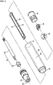
- FIG. 1 is a perspective view illustrating the proximity sensor 510 of Embodiment 1.
- FIG. 2 is a perspective view illustrating an exploded state of the proximity sensor 510 of Embodiment 1.
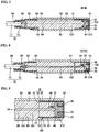
- FIG. 3 is a cross-sectional view taken along the line III-III of FIG. 1 .
- FIG. 4 is a cross-sectional view taken along the line IV-IV of FIG. 1 .
- FIG. 5 is an enlarged cross-sectional view illustrating the vicinity of a detecting unit 210 included in the proximity sensor 510 of Embodiment 1.
- the proximity sensor 510 is an inductive proximity sensor that generates a magnetic field in a detection region to detect whether or not a detection target is approaching or present.
- the detection target that is detected by the proximity sensor 510 is a conductive object.
- the detection target that is detected by the proximity sensor 510 typically includes magnetic metal such as iron.
- the detection target that is detected by the proximity sensor 510 may also include nonmagnetic metal such as copper or aluminum.
- the proximity sensor 510 has an outer appearance extending cylindrically along a phantom central axis 102 (see FIGS. 3 and 4 ).
- the proximity sensor 510 includes the detecting unit 210 (see FIGS. 3 to 5 ), a coil case 20, a printed board 50 (see FIGS. 2 to 5 ), a base metal fitting 60, which serves as a housing, a clamp 80, and a ring cord 70.
- the detecting unit 210 detects whether or not a detection target is approaching or present.
- the detecting unit 210 generates a magnetic field by flowing a current through a coil, and detects whether or not a detection target is approaching or present using an electromagnetic interaction between the generated magnetic field and the detection target.
- the detecting unit 210 is provided on the front end side of the proximity sensor 510 that faces the detection region.
- the detecting unit 210 mainly includes a core 40, an electromagnetic coil 36 (see FIGS. 3 to 5 ), and a coil spool 30 (see FIGS. 2 to 5 ).
- the core 40 is made from a material having an excellent high frequency property, such as ferrite, for example.
- the core 40 has the function to increase the coil characteristics (e.g. inductivity) of the detecting unit 210, and to concentrate magnetic fluxes in the detection region.
- the electromagnetic coil 36 is formed by a coil wire being wound on the coil spool 30.
- the electromagnetic coil 36 is wound around the central axis 102.
- the central axis around which the electromagnetic coil 36 is wound is configured to be identical with the central axis 102.
- the coil spool 30 is made from an electric insulating resin.
- the coil spool 30 is accommodated in a circular groove formed in the core 40.
- a coil pin 46 is made from conductive metal.
- the coil pin 46 is supported by the coil spool 30.
- the coil pin 46 has the shape of protruding from the detecting unit 210 to the printed board 50.
- the protruding end of the coil pin 46 is connected to a conductive region formed on the printed board 50.
- An end 37 of the electromagnetic coil 36 that is drawn from the outer circumference of the coil spool 30 is wound around the root section of the coil pin 46 that protrudes from the detecting unit 210.
- the electromagnetic coil 36 and the printed board 50 are electrically connected to each other via the coil pin 46 and solder (not shown).
- the detecting unit 210 is accommodated in the coil case 20.
- the coil case 20 functions as a front cover that is mounted in an opening on the front end side of the base metal fitting 60.
- the coil case 20 is typically made from a material such as a thermoplastic resin that has an excellent adhesive property to a resin with which a resin section 120 is formed.
- a material of the coil case 20 may appropriately be selected from, for example, ABS, PC (polycarbonate), POM (polyacetal), PBT (polybutylene terephthalate), PA (polyamide), PE (polyethylene), PP (polypropylene), PES (polyether sulfone), PPS (Polyphenylenesulfide), LCP (liquid crystal polymer), and PS (polystyrene), and mixtures thereof.
- ABS polycarbonate
- POM polyacetal
- PBT polybutylene terephthalate
- PA polyamide
- PE polyethylene
- PP polypropylene
- PES polyether sulfone
- PPS Polyphenylenesulfide
- LCP liquid crystal polymer
- PS polystyrene
- the coil case 20 is provided so as to serve as a cover for the front end side on which the detecting unit 210 is accommodated.
- the coil case 20 can function as a closing member for closing the base metal fitting 60, and fills up the opening on the front end side (that is, on opening 61 on one side) of the base metal fitting 60, which serves as a main case, which may also be referred to as "casing".
- the coil case 20 is provided mainly for blocking and protecting the detecting unit 210 from the outer atmosphere.
- the coil case 20 has the shape of a cylinder with a bottom.
- the coil case 20 cylindrically extends along the central axis 102, and has such a shape that one end thereof is closed and the other end thereof is open.
- the end face of the coil case 20 on the closed end side constitutes a detection surface of the proximity sensor 510.
- the detecting unit 210 is arranged inside the tubular section of the coil case 20.
- the printed board 50 has an elongated flat plate shape.
- the printed board 50 extends such that the longitudinal direction thereof is the axial direction of the central axis 102.
- the printed board 50 has side faces 52 that extend in the longitudinal direction (see FIGS. 2 and 3 ).
- Various types of electronic components such as a transistor, a diode, a resistor, and a capacitor, are mounted on the printed board 50. These electronic components are sealed by a resin, and encompass components that are electrically connected to the detecting unit 210.
- the base metal fitting 60 functions as a tubular main case for accommodating the electronic components such as a transistor, a diode, a resistor, and a capacitor.
- the base metal fitting 60 is closed by the coil case 20 on one end (namely, the opening 61 on one end).
- the base metal fitting 60 forms a contour of the proximity sensor 510 at a certain distance from the central axis 102.
- the base metal fitting 60 has the shape of cylindrically extending along the central axis 102.
- the shape of the base metal fitting 60 is not limited to that cylindrical shape, and may also be other cylindrical shapes such as a rectangular cylinder, a polyangular cylinder, or an elliptic cylinder.
- the main case may be made from a resin member.
- an accommodation section 85 which serves as an accommodation space, is formed inside these components.
- the printed board 50 and the electronic components, together with the resin section 120 are located in the accommodation section 85. That is, the printed board 50 and the electronic components are arranged in the internal space enclosed by the base metal fitting 60, which serves as the main case, and the coil case 20, which serve as the closing members.
- the base metal fitting 60 extends around the central axis 102 and is opened on its two ends.
- the base metal fitting 60 has the opening 61 on one end side in the longitudinal direction, and an opening 62 on the other end side in the longitudinal direction.
- the openings 61 and 62 communicate with each other via the internal space formed inside an inner surface 63 of the base metal fitting 60.
- the inner surface 63 of the present embodiment is circular, when seen in the cross-sectional view in the direction that is orthogonal to the central axis 102, at any position in the direction in which the central axis 102 extends.
- the base metal fitting 60 is made from metal.
- the base metal fitting 60 includes, on its outer circumferential surface, a screw for use for fixing the proximity sensor 510 to external equipment.
- the above-described coil case 20 is inserted into the opening 61 of the base metal fitting 60 on one end side, and is fixed to the base metal fitting 60. As described above, the coil case 20 can serve as a closing member, and closes the opening 61 of the base metal fitting 60..
- the clamp 80 is provided as a connection member that is connected to the base metal fitting 60 from the rear end side of the proximity sensor 510.
- the clamp 80 is connected to the rear end of the cylindrical base metal fitting 60.
- the clamp 80 is inserted into the opening on the rear end side of the base metal fitting 60 (that is, the other opening 62).
- the clamp 80, together with the base metal fitting 60 extends cylindrically along the central axis 102.
- the ring cord 70 is electrically connected to the printed board 50 inside the accommodation section 85.
- the ring cord 70 is inserted into the clamp 80 and drawn from an opening 88 on the rear end side of the clamp 80 (rear end of the accommodation section 85).
- the ring cord 70 closes the opening 88 on the rear end side of the clamp 80 (rear end of the accommodation section 85).
- the ring cord 70 and the clamp 80 integrated into one piece, close the opening (the other opening 62) on the rear end side of the cylindrical base metal fitting 60.
- the ring cord 70 includes a cable 71 and a ring member 72.
- the ring member 72 is provided so as to cover an end of the cable 71 in the cylindrical case 310.
- the ring member 72 ensures connectivity between the resin section 120, which is provided in the accommodation section 85 and will be described later, and the cable 71.
- the ring member 72 is made from, for example, PBT (polybutylene terephthalate).
- the cable 71 is covered with, for example, polyvinyl chloride.
- the resin section 120 is formed by a resin being injected into an internal space (in the accommodation section 85) of the base metal fitting 60, which serves as the main case.
- the resin section 120 is located in the accommodation section 85, which is surrounded by the base metal fitting 60, the coil case 20, which closes one opening 61 of the base metal fitting 60, and the ring cord 70 and the clamp 80, which close the other opening 62 of the base metal fitting 60, and is formed as an accommodation space inside these components.
- the resin section 120 seals the detecting unit 210 accommodated in the coil case 20, the printed board 50 accommodated in the cylindrical case 310, and electronic components mounted on the printed board 50.
- the resin of the resin section 120 is selected from, for example, a thermoplastic resin, a thermosetting resin, a light curable resin, an ultraviolet curable resin, and a moisture curable resin.
- the resin of the resin section 120 is selected from a thermoplastic resin and a thermosetting resin, and seals the detecting unit 210 (the core 40, the electromagnetic coil 36, and the coil spool 30).
- thermoplastic resin that is used for formation of the resin section 120 is at least one type selected from the group consisting of polyolefins, polyesters, and polyamides, for example.
- the thermoplastic resin that is used for formation of the resin section 120 may include various types of additive agents such as a flame retarder, an organic/inorganic filler, a plasticizer, a coloring agent, and an antioxidant.
- a thermoplastic resin having a hardness (shore D) of 60 or less it is possible to reduce a stress on the internal devices such as electronic components or the printed board 50.
- a thermoplastic resin that is used for formation of the resin section 120 is preferably a so-called hot melt resin.
- thermosetting resin an epoxy resin is typically used.
- the resin section 120 preferably has a low variation in resin stress (relaxation of stress) that is affected on the detecting unit 210.
- the thermosetting resin that is used for the resin section 120 is preferably a resin whose elastic modulus at ambient temperature is 800 MPa or more.
- the thermosetting resin that is used for the resin section 120 may include various types of additive agents such as a flame retarder, an organic/inorganic filler, a plasticizer, a coloring agent, and an antioxidant.
- a resin of the resin section 120 a resin having a relatively high linear expansion coefficient of, for example, 90 ⁇ 10 -6 /°C or more may be used. Even when such a resin having a high linear expansion coefficient is used for the resin section 120, adopting the configuration according to the embodiment as will be described below can ensure the sealing property even under the use environment of the electronic device in which a temperature difference is large.
- the resin section 120 has a shape extending from the coil case 20 (one opening 61) to the ring cord 70 and clamp 80 (the other opening 62).
- shape extending " includes shapes of the resin section 120 that extend from the ring cord 70 and clamp 80 to the coil case 20.
- an extension section 22 is formed between the coil case 20 and the resin section 120.
- the extension section 22 has a configuration for improving the sealing property between the coil case 20 and the resin section 120, in particular, for ensuring the sealing property under the use environment of the electronic device in which a temperature difference is large.
- an extension section having a step structure with an anchoring section 24 is provided on the outer periphery of an open end of the coil case 20 including a rib-shaped section 23.
- a gap 130 is formed between the base metal fitting 60 and the open end 21 on the rear end side of the coil case 20.
- the gap 130 forms a tubular space that has a shape corresponding to that of the base metal fitting 60, namely, the shape of a cylinder in the present embodiment.
- the gap 130 is formed over the entire circumference of the extension section 22 between the extension section 22 extending from the coil case 20 and the inner surface 63 of the base metal fitting 60 so as to surround the extension section 22 from the outside in the radial direction. That is, the coil case 20, serving as a closing member, includes the extension section 22 that forms a space that is filled with a resin between the extension section 22 and the base metal fitting 60 over the entire circumference that is opposite to the inner surface 63 of the base metal fitting 60, serving as the main case.
- FIG. 6 is a cross-sectional view schematically illustrating the extension section 22 that is used for the proximity sensor of Embodiment 1.
- the direction in which the central axis 102 extends is defined as the Z axis
- the two-dimensional surface when viewed in a cross section in the direction that is orthogonal to the axial direction of the central axis 102 is defined by the X and Y axes.
- the extension section 22 uses a thinned sealing structure in which the thickness of the resin section is relatively small, expansion and contraction stresses in the direction (Z direction) in which the resin section extends are removed. That is, the resin section that is present in a space between the rib-shaped section 23 of the coil case 20 and the inner surface 63 of the base metal fitting 60 is referred to also as “base end section 121" or “A section", for ease of description.
- base end section 121 By setting a thickness DA of the base end section 121 to 0.2 mm to 1.0 mm for example, it is possible to set the expansion and contraction stresses of the resin section occurring in the Z direction due to a temperature change to substantially zero.
- the expansion and contraction stresses occurring in the Z direction induces the resin section 120 to be detached from the outer surface of the coil case 20, but this phenomenon is suppressed by appropriately designing the thickness of the resin section.
- the extension section 22 has an anchoring section 24 that forms a step with respect to the rib-shaped section 23.
- the resin section that is present between the anchoring section 24 of the coil case 20 and the inner surface 63 of the base metal fitting 60 is referred to also as “top end section 122" or “B section", for ease of description.
- a bent section 26 of the anchoring that is present between the rib-shaped section 23 of the extension section 22 and the anchoring section 24 receives, on its surface, expansion and contraction stresses of the resin section as press stresses. Accordingly, by converting expansion and contraction stresses of the resin section into press stresses, it is possible to suppress the resin section from being detached from the coil case 20 and the inner surface 63 of the base metal fitting 60.
- the gap 130 is formed between the base metal fitting 60 and the open end 21 on the rear end side of the coil case 20.
- a resin with which the gap 130 is filled includes the base end section 121 and the top end section 122, which are provided in the space (gap 130) formed by the extension section 22 that is an extension section.
- the extension section 22 functions as an engagement structure for preventing, on the entire circumference thereof, the resin section of the base end section 121 from being shifted in the direction of the central axis 102 of the main case.
- engagement structure includes the function to remove expansion and contraction stresses occurring to the injected resin in the Z direction (central axis direction) due to a temperature change, and/or, the function of guiding the expansion and contraction stress that have occurred, in another direction.
- the “engagement structure” may have, in addition to the below described configuration, any configuration that is obtained by the extension section 22 being cut 360-degree several times intermittently so as to be corrugated, textured, polka-dotted, or the like, as long as it exerts an effect for preventing the resin section from being shifted.
- the inventors of the present application found a new fact that, by making the thickness of the resin section in the direction from the central axis 102 of the base metal fitting 60 (main case) to the base metal fitting 60 (thickness in the radial direction) relatively thin, it is possible to substantially remove expansion and contraction stresses of the resin section occurring in the Z direction due to a temperature change.
- the reason is that it is presumed that the thickness of the resin section by which the resin section is caught without an influence of a temperature is 0.2 mm to 1.0 mm, and from this presumption, it is considered that, when the thickness of the resin section is maintained as 0.2 mm to 1.0 mm, the thickness can be maintained irrespective of the surface state, making it possible to suppress expansion and contraction stresses from occurring.
- a thickness DA of the base end section 121 in the direction that is orthogonal to the central axis direction is 0.2 to 1.0 mm.
- a thickness DB of the top end section 122 (B section) in the direction from the central axis 102 of the base metal fitting 60 (main case) toward the base metal fitting 60 is configured to be larger than the thickness DA of the base end section 121 (A section).
- the resin section provided in the gap 130 having the engagement structure of the present embodiment includes the base end section 121 that has the thickness DA (first thickness) in the direction from the central axis 102 of the base metal fitting 60 (main case) toward the base metal fitting 60 (main case), and the top end section 122 that has the thickness DB (second thickness) in the direction from the central axis 102 of the base metal fitting 60 (main case) toward the base metal fitting 60 (main case) that is larger than the thickness DA.
- DA first thickness
- DB second thickness
- the thickness DB of the top end section 122 in the direction from the central axis 102 of the base metal fitting 60 (main case) toward the base metal fitting 60 is preferably larger than the thickness DA of the base end section 121 by 0.1 mm or more.
- the upper limit of the thickness DB of the top end section 122 in the direction from the central axis 102 of the base metal fitting 60 (main case) toward the base metal fitting 60 is preferably set to 1.5 mm.
- a structure in which the base end section 121 (A section) and the top end section 122 (B section) are formed adjacent to each other in the axial direction of the central axis 102 is taken as an example of the engagement structure of the present embodiment, but the present invention is not limited to this structure as long as the structure exerts the anchoring effect, as will be described below.
- Embodiment 1 shows an example in which a hot melt resin, which is a thermoplastic resin, is used for a resin seal.
- An IP67 test defined by International Electrotechnical Commission (IEC) and Japanese Industrial Standards (JIS) is used as a method for evaluating water resistance, and excellence of water resistance is determined based on whether or not the insulating resistance value exceeds 50 M ⁇ .
- a method for evaluating thermal shock resistance is performed where an operation (repeated thermal shock) in which a product to be evaluated is exposed to the environments of -25°C and 70°C each for 30 minutes is regarded as one cycle, the product is subjected to that cycle one hundred times repeatedly, and then excellence of thermal shock resistance is determined based on whether or not the insulating resistance value exceeds 50 M ⁇ .
- an operation replicated thermal shock
- excellence of thermal shock resistance is determined based on whether or not the insulating resistance value exceeds 50 M ⁇ .
- Pass shows that the insulating resistance value exceeds 50 M ⁇
- “Fail” shows that the insulating resistance value is 50 M ⁇ or less.
- Examples 1 to 4 shown in the table below are examples in which the thickness of the base end section 121 is varied in the range from 0.2 mm to 1.0 mm, and the thickness of the top end section 122 is also varied with variation in thickness of the base end section 121, so as to satisfy the above-described condition (2). Note that the top end section 122 is assumed to be convex-shaped with respect to the base end section 121.
- Examples 1, and 5 to 7 shown in the table below are examples in which the thickness of the base end section 121 is 0.2 mm, and the thickness of the top end section 122 is varied in the range from 0.2 to 1.6 mm.
- Examples 4, and 8 to 10 shown in the table below are examples in which the thickness of the base end section 121 is 1.0 mm, and the thickness of the top end section 122 is varied in the range from 1.0 to 1.6 mm.
- Example 2 differs from the foregoing Example 1 only in the material that constitutes the resin section 120, and uses the same examples of design of the thicknesses of the base end section 121 and the top end section 122, and the same method for evaluating the water resistance and shock resistance as those of Example 1.
- Examples 1A to 4A shown in the table below are examples in which the thickness of the base end section 121 is varied in the range from 0.2 mm to 1.0 mm, and the thickness of the top end section 122 is also varied with variation in thickness of the base end section 121, so as to satisfy the above-described condition.
- Examples 1A, and 5A to 7A shown in the table below are examples in which the thickness of the base end section 121 is 0.2 mm, and the thickness of the top end section 122 is varied in the range from 0.2 to 1.6 mm. Furthermore, Examples 4, and 8 to 10 shown in the table below are examples in which the thickness of the base end section 121 is 1.0 mm, and the thickness of the top end section 122 is varied in the range from 1.0 to 1.6 mm.
- the thermal shock resistance may be deteriorated by a repeated thermal shock for the same reason as that of Comparative Examples 4 and 6 of Example 1.
- the following shows the results of evaluation about water resistance and shock resistance of a proximity sensor of the present embodiment, the results being obtained while varying the lateral lengths (length in the axial direction of the central axis 102) of the base end section 121 and top end section 122.
- the above-described condition (1) is determined in view of the exertion of the anchoring effect and the fillability with resin. More specifically, when the total length in the lateral direction of the base end section 121 and the top end section 122 is less than 1.0 mm, the anchoring effect cannot substantially be exerted. On the other hand, when the total length in the lateral direction of the base end section 121 and the top end section 122 exceeds 10.0 mm, the fillability with resin is deteriorated. Accordingly, the total length of the length of the base end section 121 (A section) in the axial direction of the central axis 102, and the length of the top end section 122 (B section) in the axial direction is preferably designed to be from 1.0 mm to 10.0 mm.
- the above-described condition (2) is classified depending on the significance of the influence when the top end section 122 is detached in the thickness direction, and when the influence when the top end section 122 is detached in the thickness direction is relatively large ((2-1) is applied when the thickness of the top end section 122 exceeds 1.0 mm), the relationship "length of the base end section 121 > length of the top end section 122" needs to be satisfied. Whereas, when the influence when the top end section 122 is detached in the thickness direction is relatively small ((2-2) is applied when the thickness of the top end section 122 is 1.0 mm or less), the lengths of the base end section 121 and the B section are suitably determined in a range in which another condition is satisfied.
- condition (3) is a condition for ensuring the fillability with resin.
- the following will describe the experiment results in which the conditions (1) to (3) are derived. Note that, in the following experiment results, an example in which a hot melt resin, which is a thermoplastic resin, is used as a resin seal is taken, but the same results are also obtained when a thermosetting resin is used.
- the required water resistance and shock resistance cannot be exerted. More specifically, since the total length in the lateral direction of the resin section 120 (the base end section 121 and the top end section 122) exceeds 10.0 mm, the fillability with resin is deteriorated. Therefore, the required water resistance and shock resistance cannot be exerted.
- Example 11 in which the total length in the lateral direction of the base end section 121 and the top end section 122 is in the range from 1.0 mm to 10.0 mm, satisfy the requirements of the water resistance and shock resistance.
- Example 11 is determined to show the lower limit of the total length in the lateral direction since the individual variation in thermal shock resistance starts occurring
- Example 14 is determined to show the upper limit of the total length in the lateral direction since the individual variation in fillability with resin of the top end section 122 starts occurring.
- the following shows, as the experiment results in which the above-described (2-1) was derived, the results that are obtained when the lengths in the lateral direction of the base end section 121 and the top end section 122 are varied respectively, taking the case in which the thickness of the base end section 121 is 0.5 mm and the thickness of the top end section 122 is 1.1mm, and the angle given by the border between the base end section 121 and the top end section 122 is 90°, as a standard.
- Example 15 is determined to show the limit value with respect to the size relation of the length in the lateral direction of the base end section 121 and of the top end section 122, since the individual variation in thermal shock resistance starts occurring.
- the following shows, as the experiment results in which the above-described (2-2) was derived, the results that are obtained when the lengths in the lateral direction of the base end section 121 and the top end section 122 are varied respectively, taking the case in which the thickness of the base end section 121 is 0.5 mm and the thickness of the top end section 122 is 1.0 mm, and the angle given by the border between the base end section 121 and the top end section 122 is 90°, as a standard.
- Comparative Example 9 and Example 20 show examples in which the total length in the lateral direction of the base end section 121 and the top end section 122 is 1.0 mm
- Comparative Example 10 and Examples 22 and 23 show examples in which the total length in the lateral direction of the base end section 121 and the top end section 122 is 10.0 mm.
- an extension section that has an anchoring section on the outer periphery of an open end of a closing member is provided in a fitting section between a main case (in the above-described examples, the base metal fitting 60) and a closing member (in the above-described examples, the coil case 20).
- the degree of freedom of the material option of the closing member that is, to eliminate, for example, a restriction depending on the property such as the bending elastic modulus.
- Embodiment 2 shows an example of a configuration in which an inclination angle between the base end section 121 (A section) and the top end section 122 (B section) is varied.
- FIG. 7 is a cross-sectional view schematically illustrating an extension section 22 that is used for a proximity sensor Embodiment 2. Note that the X axis, the Y axis, and Z axis show the same directions as those in the cross-sectional view of FIG. 6 .
- the base end section 121 is tapered toward the top end section 122 from the open end 21 of the coil case 20 on the rear side. That is, the resin section provided in the gap 130 formed by the engagement structure of the present embodiment is configured so as to further form an intermediate section 123 between the base end section 121 (A section) and the top end section 122 (B section).
- the intermediate section 123 is configured such that its thickness from the central axis of the base metal fitting 60 (main case) toward the base metal fitting 60 varies along the axial direction, generating, when a force for letting the top end of the base end section 121 (A section) be closer to the top end section 122 (B section) is generated due to contraction of the resin section, a reactive force in the axial direction of the central axis 102 to the extension section 22.
- the top end section 122 is convex-shaped with respect to the base end section 121, and the inclination angle of the intermediate section 123 toward the top end section 122 from the base end section 121 is constant.
- the angle ⁇ given by the surface of the intermediate section 123 and the central axis 102 is defined as "an angle given by a border between the base end section 121 and the top end section 122".
- the intermediate section 123 is directed in the direction that is orthogonal to the central axis 102, and this corresponds to the case where the angle ⁇ given by the border of the base end section 121 and the border of the top end section 122 is 90°.
- the angle ⁇ given by the border of the base end section 121 and the border of the top end section 122 is in the range from 90° to 150°.
- the bent section 26 cannot receive the stress that affects the detachment as a press stress, and does not exert the anchoring effect.
- the inclination angle of the intermediate section 123 (the angle ⁇ given by the border of the base end section 121 and the border of the top end section 122) is preferably 90° to 150° in view of molding of the coil case 20 (preventing a metal mold undercut structure for the bent section 26), and exertion of the anchoring effect.
- Examples 24 to 26, and Comparative Examples 11 and 12 shown in the table below show the results obtained when the angle given by the border between the base end section 121 and the top end section 122 is varied, taking the case in which the thickness of the base end section 121 is 0.9 mm and the thickness of the top end section 122 is 1.0 mm, as a standard.
- extension section 22 in addition to the advantages achieved by the foregoing Embodiment 1, moldability in manufacturing of the extension section 22 (extension section) can be improved since the angle given by the border between the base end section 121 and the top end section 122 can be made larger than 90°, further improving the production yield of the closing member.
- the intermediate section 123 may have any shape as long as the anchoring effect is exerted.
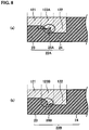
- the shape in which this anchoring effect is exerted will be described with reference to FIGS. 8 to 10 .
- FIG. 8 shows cross-sectional views schematically illustrating extension sections that are used for a proximity sensor of the Embodiment 3.
- FIG. 9 shows cross-sectional views schematically illustrating other extension sections that are used for the proximity sensor of Embodiment 3.
- FIG. 10 shows cross-sectional views schematically illustrating yet other extension sections that are used for the proximity sensor of Embodiment 3.
- FIG. 8(a) schematically shows the resin section that is filled with a resin and is adjacent to the extension section 22A, such that the base end section 121 that is adjacent to the rib-shaped section 23, the intermediate section 123A that is adjacent to the bent section 26A, and the top end section 122 that is adjacent to the anchoring section 24 are clearly distinguished from one another. Note, however, that in the manufacture stage, it is not necessary to clearly distinguish these sections (the same applies to FIGS. 8(a) , 9(a) , 9(b) , 10(a), and 10(b) , which will be described later).
- the extension section 22A includes, between the rib-shaped section 23 and the anchoring section 24, the bent section 26A having the convex-shaped projection on the surface thereof.
- the bent section 26A receives, with the projection on the surface, expansion and contraction stresses generated in the resin section as press stresses.
- an extension section 22B shown in FIG. 8(b) adopts a bent section 26B that has a recess. That is, the extension section 22B includes, between the rib-shaped section 23 and the anchoring section 24, the bent section 26B having the recess on the surface thereof. The bent section 26B receives, with the recess on the surface, expansion and contraction stresses generated in the resin section as press stresses.
- the extension sections shown in FIGS. 8(a) and 8(b) have the projection and the recess on the bent sections 26A and 26B, respectively.
- This projection and recess may have any structure as long as the metal mold for used in molding is not an undercut mold.
- the tips of the formed projection and the bottom recess have preferably an acute angle.
- the border between the intermediate section 123A, 123B and the extension section 22A, 22B is formed on the line that connects an end of a border between the base end section 121 (A section) and the extension section 22A, 22B, to an end of a border between the top end section 122 (B section) and the extension section 22A, 22B, the ends being close to each other, and has the projection whose top has an acute angle or the recess whose bottom has an acute angle.
- an extension section 22C shown in FIG. 9(a) adopts a bent section 26C that has multiple angles.
- the extension section 22C has, between the rib-shaped section 23 and the anchoring section 24, the bent section 26C having multiple angles when viewed in a cross section.
- an extension section 22D shown in FIG. 9(b) adopts a bent section 26D that has multiple angles.
- the bent sections 26C and 26D receive, with the multiple angles on their surfaces, expansion and contraction stresses generated in the resin section as press stresses.
- extension sections shown in FIGS. 9(a) and 9(b) have the bent sections having multiple angles (polygon), and the multiple angles may be of any structure as long as the metal mold for use in molding is not an undercut mold.
- the border between the intermediate section 123C, 123D and the extension section 22C, 22D is formed by a combination of a plurality of lines and, of the plurality of lines, any of pairs of two adjacent lines, namely, a pair of the border between the base end section 121 (A section) and the extension section 22C, 22D, and the adjacent line, and a pair of the border between the top end section 122 (B section) and the extension section 22C, 22D, and the adjacent line is configured to have a larger angle than the right angle.
- an extension section 22E shown in FIG. 10(a) adopts a bent section 26E that has a curved surface.
- the extension section 22E has, between the rib-shaped section 23 and the anchoring section 24, the bent section 26F that is arc-shaped when viewed in the cross section.
- an extension section 22F shown in FIG. 10(b) adopts a bent section 26F that has a curved surface.
- the bent sections 26F and 26F receive, with their curved surface, expansion and contraction stresses generated in the resin section as press stresses.
- the bent sections 26E, 26F are formed so as to have a curved surface, and this curved surface may have any structure as long as the metal mold for use in molding is not an undercut mold.
- extension section 22 in addition to the advantages achieved by the foregoing Embodiment 1, moldability in manufacturing of the extension section 22 (extension section) can be improved since the shape of the intermediate section 123 and the adjacent bent section between the base end section 121 and the top end section 122 can be designed relatively freely, further improving the production yield of the closing member.
- any cross-sectional shape may be used for the present invention as long as the base metal fitting 60 and the coil case 20 are tubular.
- a tubular base metal fitting and a tubular coil case that have any polygonal cross-sectional shape may be used.
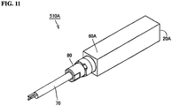
- FIG. 11 is a perspective view illustrating a proximity sensor 510A of Embodiment 4.
- the proximity sensor 510A shown in FIG. 11 has an outer appearance extending in the shape of a quadrangular prism along the central axis.
- the proximity sensor 510A includes a detecting unit (not shown), a coil case 20A, the printed board (not shown), a base metal fitting 60A, which serves as a housing, the clamp 80A, and the ring cord 70.
- the engagement structure formed in the proximity sensor 510A of the present embodiment is the same as the engagement structures of the foregoing Embodiments 1 to 3, and detailed descriptions thereof are not repeated.
- the present invention is not limited to the proximity sensor.
- the present invention may be applicable to a photoelectric sensor, a fiber sensor, a smart sensor, or the like.
- a photoelectric sensor detects presence or absent of an object, a change in a surface state, or the like, using various properties of light emitted from a light emission source.
- a detecting unit of the photoelectric sensor includes, as the light emission source, a light emitting diode, a semiconductor laser, or the like.
- a fiber sensor is a sensor in which an optical fiber is incorporated with a photoelectric sensor.
- a detecting unit of the fiber sensor as well includes, as the light emission source, a light emitting diode, a semiconductor laser, or the like.
- a smart sensor is a sensor that has, in added to functions of a proximity sensor or a photoelectric sensor, functions to perform analysis and information processing.
- a detecting unit corresponds to any one of the detecting units of the above-described embodiments, whereas in the case where a photoelectric sensor is used as a basic configuration of the smart sensor, a light emitting diode, a semiconductor laser, or the like is included as a light emission source.
Landscapes
- Engineering & Computer Science (AREA)
- Microelectronics & Electronic Packaging (AREA)
- Casings For Electric Apparatus (AREA)
- Transmission And Conversion Of Sensor Element Output (AREA)
- Switches That Are Operated By Magnetic Or Electric Fields (AREA)
Applications Claiming Priority (1)
| Application Number | Priority Date | Filing Date | Title |
|---|---|---|---|
| JP2014052567A JP6269202B2 (ja) | 2014-03-14 | 2014-03-14 | 電子機器 |
Publications (2)
| Publication Number | Publication Date |
|---|---|
| EP2919567A1 EP2919567A1 (en) | 2015-09-16 |
| EP2919567B1 true EP2919567B1 (en) | 2018-02-14 |
Family
ID=51870809
Family Applications (1)
| Application Number | Title | Priority Date | Filing Date |
|---|---|---|---|
| EP14189870.0A Active EP2919567B1 (en) | 2014-03-14 | 2014-10-22 | Electronic device |
Country Status (3)
| Country | Link |
|---|---|
| EP (1) | EP2919567B1 (es) |
| JP (1) | JP6269202B2 (es) |
| CN (1) | CN104908182B (es) |
Families Citing this family (16)
| Publication number | Priority date | Publication date | Assignee | Title |
|---|---|---|---|---|
| JP2017092192A (ja) * | 2015-11-06 | 2017-05-25 | オムロン株式会社 | 電子機器の製造方法および電子機器 |
| JP2017092193A (ja) * | 2015-11-06 | 2017-05-25 | オムロン株式会社 | 電子機器 |
| JP2017092354A (ja) * | 2015-11-13 | 2017-05-25 | オムロン株式会社 | 電子機器 |
| DE202016101136U1 (de) * | 2016-03-03 | 2017-06-09 | Tridonic Gmbh & Co Kg | Elektronisches Bauteil |
| DE102016220773A1 (de) * | 2016-10-21 | 2018-04-26 | Ifm Electronic Gmbh | Verfahren zur Endfertigung eines Näherungsschalters zur berührungslosen Erfassung eines Targets in einem Überwachungsbereich und Näherungsschalter zur berührungslosen Erfassung eines Targets in einem Überwachungsbereich |
| DE102017109199A1 (de) | 2017-04-28 | 2018-10-31 | Omron Corporation | Elektronische Vorrichtung |
| DE102017109187A1 (de) | 2017-04-28 | 2018-10-31 | Omron Corporation | Elektronische Vorrichtung |
| US9949392B1 (en) | 2017-05-02 | 2018-04-17 | Omron Corporation | Electronic apparatus |
| US10045453B1 (en) | 2017-05-02 | 2018-08-07 | Omron Corporation | Electronic apparatus and electric cable sealed therein |
| US10123438B1 (en) | 2017-05-02 | 2018-11-06 | Omron Corporation | Electronic apparatus and method of manufacturing same |
| CN108811409B (zh) * | 2017-05-04 | 2020-06-23 | 欧姆龙株式会社 | 电子机器 |
| CN108808618B (zh) * | 2017-05-04 | 2020-06-23 | 欧姆龙株式会社 | 电子机器的制造方法及电子机器 |
| CN108811408A (zh) * | 2017-05-04 | 2018-11-13 | 欧姆龙株式会社 | 电子机器 |
| JP7033274B2 (ja) | 2018-11-12 | 2022-03-10 | オムロン株式会社 | センサ及びその製造方法 |
| CN109887781B (zh) * | 2019-04-04 | 2021-09-10 | 上海科世达-华阳汽车电器有限公司 | 一种传感元器件连接结构 |
| TWI841329B (zh) * | 2023-03-30 | 2024-05-01 | 佳必琪國際股份有限公司 | 防水電連接裝置 |
Family Cites Families (5)
| Publication number | Priority date | Publication date | Assignee | Title |
|---|---|---|---|---|
| JPH03257733A (ja) * | 1990-03-08 | 1991-11-18 | Omron Corp | 電子スイッチ |
| DE4023792C2 (de) * | 1990-07-26 | 2000-05-11 | Siemens Ag | Verfahren zur Herstellung eines Näherungsschalters mit Befestigungshülse |
| JPH06103869A (ja) * | 1992-09-17 | 1994-04-15 | Fuji Electric Co Ltd | 近接スイッチ |
| JPH06349392A (ja) * | 1993-06-02 | 1994-12-22 | Omron Corp | 電子スイッチ |
| JP3279187B2 (ja) * | 1995-07-18 | 2002-04-30 | オムロン株式会社 | 近接センサとその製造方法 |
-
2014
- 2014-03-14 JP JP2014052567A patent/JP6269202B2/ja active Active
- 2014-10-16 CN CN201410546859.2A patent/CN104908182B/zh active Active
- 2014-10-22 EP EP14189870.0A patent/EP2919567B1/en active Active
Non-Patent Citations (1)
| Title |
|---|
| None * |
Also Published As
| Publication number | Publication date |
|---|---|
| CN104908182A (zh) | 2015-09-16 |
| CN104908182B (zh) | 2017-12-15 |
| JP6269202B2 (ja) | 2018-01-31 |
| JP2015177042A (ja) | 2015-10-05 |
| EP2919567A1 (en) | 2015-09-16 |
Similar Documents
| Publication | Publication Date | Title |
|---|---|---|
| EP2919567B1 (en) | Electronic device | |
| JP4561613B2 (ja) | 磁気センサ | |
| EP2884826B1 (en) | Electronic device | |
| US10466073B2 (en) | Proximity sensor | |
| US9568388B2 (en) | Small form factor pressure sensor | |
| EP1975572A1 (en) | Sensor apparatus | |
| JP2014055911A (ja) | 無接触型ポテンショメータ | |
| EP2775514B1 (en) | Resin-sealed electronic device | |
| US10779426B2 (en) | Proximity sensor | |
| CN203365699U (zh) | 检测传感器 | |
| CN107453116A (zh) | 具有编码功能的电连接器 | |
| JP2013162003A (ja) | コアホルダ及び電流センサ | |
| EP2775623B1 (en) | Electronic device and producing method thereof | |
| JP6060777B2 (ja) | 電子機器およびその製造方法 | |
| KR101919477B1 (ko) | 봉지 부재 부착 차폐 케이블 | |
| US11664802B2 (en) | Proximity sensor | |
| JP6323066B2 (ja) | 電子機器 | |
| JP6058401B2 (ja) | 磁気センサ装置 | |
| JP2014035322A (ja) | コアホルダ及び電流センサ | |
| KR20160002750U (ko) | 센서 캐리어 및 센서 | |
| US20200287328A1 (en) | Electrical connector with flexible bellows | |
| EP2919568B1 (en) | Electronic device | |
| JP2013160668A (ja) | コアホルダ及び電流センサ | |
| JP2014172273A (ja) | 電子機器およびその製造方法 | |
| JP2018165716A (ja) | 電流検出器 |
Legal Events
| Date | Code | Title | Description |
|---|---|---|---|
| PUAI | Public reference made under article 153(3) epc to a published international application that has entered the european phase |
Free format text: ORIGINAL CODE: 0009012 |
|
| 17P | Request for examination filed |
Effective date: 20141022 |
|
| AK | Designated contracting states |
Kind code of ref document: A1 Designated state(s): AL AT BE BG CH CY CZ DE DK EE ES FI FR GB GR HR HU IE IS IT LI LT LU LV MC MK MT NL NO PL PT RO RS SE SI SK SM TR |
|
| AX | Request for extension of the european patent |
Extension state: BA ME |
|
| GRAP | Despatch of communication of intention to grant a patent |
Free format text: ORIGINAL CODE: EPIDOSNIGR1 |
|
| STAA | Information on the status of an ep patent application or granted ep patent |
Free format text: STATUS: GRANT OF PATENT IS INTENDED |
|
| INTG | Intention to grant announced |
Effective date: 20170921 |
|
| GRAS | Grant fee paid |
Free format text: ORIGINAL CODE: EPIDOSNIGR3 |
|
| GRAA | (expected) grant |
Free format text: ORIGINAL CODE: 0009210 |
|
| STAA | Information on the status of an ep patent application or granted ep patent |
Free format text: STATUS: THE PATENT HAS BEEN GRANTED |
|
| AK | Designated contracting states |
Kind code of ref document: B1 Designated state(s): AL AT BE BG CH CY CZ DE DK EE ES FI FR GB GR HR HU IE IS IT LI LT LU LV MC MK MT NL NO PL PT RO RS SE SI SK SM TR |
|
| REG | Reference to a national code |
Ref country code: GB Ref legal event code: FG4D |
|
| REG | Reference to a national code |
Ref country code: CH Ref legal event code: EP |
|
| REG | Reference to a national code |
Ref country code: IE Ref legal event code: FG4D |
|
| REG | Reference to a national code |
Ref country code: DE Ref legal event code: R096 Ref document number: 602014020892 Country of ref document: DE Ref country code: AT Ref legal event code: REF Ref document number: 970675 Country of ref document: AT Kind code of ref document: T Effective date: 20180315 |
|
| REG | Reference to a national code |
Ref country code: NL Ref legal event code: MP Effective date: 20180214 |
|
| REG | Reference to a national code |
Ref country code: AT Ref legal event code: MK05 Ref document number: 970675 Country of ref document: AT Kind code of ref document: T Effective date: 20180214 |
|
| PG25 | Lapsed in a contracting state [announced via postgrant information from national office to epo] |
Ref country code: HR Free format text: LAPSE BECAUSE OF FAILURE TO SUBMIT A TRANSLATION OF THE DESCRIPTION OR TO PAY THE FEE WITHIN THE PRESCRIBED TIME-LIMIT Effective date: 20180214 Ref country code: CY Free format text: LAPSE BECAUSE OF FAILURE TO SUBMIT A TRANSLATION OF THE DESCRIPTION OR TO PAY THE FEE WITHIN THE PRESCRIBED TIME-LIMIT Effective date: 20180214 Ref country code: NO Free format text: LAPSE BECAUSE OF FAILURE TO SUBMIT A TRANSLATION OF THE DESCRIPTION OR TO PAY THE FEE WITHIN THE PRESCRIBED TIME-LIMIT Effective date: 20180514 Ref country code: FI Free format text: LAPSE BECAUSE OF FAILURE TO SUBMIT A TRANSLATION OF THE DESCRIPTION OR TO PAY THE FEE WITHIN THE PRESCRIBED TIME-LIMIT Effective date: 20180214 Ref country code: NL Free format text: LAPSE BECAUSE OF FAILURE TO SUBMIT A TRANSLATION OF THE DESCRIPTION OR TO PAY THE FEE WITHIN THE PRESCRIBED TIME-LIMIT Effective date: 20180214 Ref country code: LT Free format text: LAPSE BECAUSE OF FAILURE TO SUBMIT A TRANSLATION OF THE DESCRIPTION OR TO PAY THE FEE WITHIN THE PRESCRIBED TIME-LIMIT Effective date: 20180214 Ref country code: ES Free format text: LAPSE BECAUSE OF FAILURE TO SUBMIT A TRANSLATION OF THE DESCRIPTION OR TO PAY THE FEE WITHIN THE PRESCRIBED TIME-LIMIT Effective date: 20180214 |
|
| PG25 | Lapsed in a contracting state [announced via postgrant information from national office to epo] |
Ref country code: AT Free format text: LAPSE BECAUSE OF FAILURE TO SUBMIT A TRANSLATION OF THE DESCRIPTION OR TO PAY THE FEE WITHIN THE PRESCRIBED TIME-LIMIT Effective date: 20180214 Ref country code: SE Free format text: LAPSE BECAUSE OF FAILURE TO SUBMIT A TRANSLATION OF THE DESCRIPTION OR TO PAY THE FEE WITHIN THE PRESCRIBED TIME-LIMIT Effective date: 20180214 Ref country code: LV Free format text: LAPSE BECAUSE OF FAILURE TO SUBMIT A TRANSLATION OF THE DESCRIPTION OR TO PAY THE FEE WITHIN THE PRESCRIBED TIME-LIMIT Effective date: 20180214 Ref country code: RS Free format text: LAPSE BECAUSE OF FAILURE TO SUBMIT A TRANSLATION OF THE DESCRIPTION OR TO PAY THE FEE WITHIN THE PRESCRIBED TIME-LIMIT Effective date: 20180214 Ref country code: BG Free format text: LAPSE BECAUSE OF FAILURE TO SUBMIT A TRANSLATION OF THE DESCRIPTION OR TO PAY THE FEE WITHIN THE PRESCRIBED TIME-LIMIT Effective date: 20180514 Ref country code: GR Free format text: LAPSE BECAUSE OF FAILURE TO SUBMIT A TRANSLATION OF THE DESCRIPTION OR TO PAY THE FEE WITHIN THE PRESCRIBED TIME-LIMIT Effective date: 20180515 |
|
| PG25 | Lapsed in a contracting state [announced via postgrant information from national office to epo] |
Ref country code: EE Free format text: LAPSE BECAUSE OF FAILURE TO SUBMIT A TRANSLATION OF THE DESCRIPTION OR TO PAY THE FEE WITHIN THE PRESCRIBED TIME-LIMIT Effective date: 20180214 Ref country code: RO Free format text: LAPSE BECAUSE OF FAILURE TO SUBMIT A TRANSLATION OF THE DESCRIPTION OR TO PAY THE FEE WITHIN THE PRESCRIBED TIME-LIMIT Effective date: 20180214 Ref country code: IT Free format text: LAPSE BECAUSE OF FAILURE TO SUBMIT A TRANSLATION OF THE DESCRIPTION OR TO PAY THE FEE WITHIN THE PRESCRIBED TIME-LIMIT Effective date: 20180214 Ref country code: PL Free format text: LAPSE BECAUSE OF FAILURE TO SUBMIT A TRANSLATION OF THE DESCRIPTION OR TO PAY THE FEE WITHIN THE PRESCRIBED TIME-LIMIT Effective date: 20180214 Ref country code: AL Free format text: LAPSE BECAUSE OF FAILURE TO SUBMIT A TRANSLATION OF THE DESCRIPTION OR TO PAY THE FEE WITHIN THE PRESCRIBED TIME-LIMIT Effective date: 20180214 |
|
| REG | Reference to a national code |
Ref country code: DE Ref legal event code: R097 Ref document number: 602014020892 Country of ref document: DE |
|
| PG25 | Lapsed in a contracting state [announced via postgrant information from national office to epo] |
Ref country code: SK Free format text: LAPSE BECAUSE OF FAILURE TO SUBMIT A TRANSLATION OF THE DESCRIPTION OR TO PAY THE FEE WITHIN THE PRESCRIBED TIME-LIMIT Effective date: 20180214 Ref country code: DK Free format text: LAPSE BECAUSE OF FAILURE TO SUBMIT A TRANSLATION OF THE DESCRIPTION OR TO PAY THE FEE WITHIN THE PRESCRIBED TIME-LIMIT Effective date: 20180214 Ref country code: SM Free format text: LAPSE BECAUSE OF FAILURE TO SUBMIT A TRANSLATION OF THE DESCRIPTION OR TO PAY THE FEE WITHIN THE PRESCRIBED TIME-LIMIT Effective date: 20180214 Ref country code: CZ Free format text: LAPSE BECAUSE OF FAILURE TO SUBMIT A TRANSLATION OF THE DESCRIPTION OR TO PAY THE FEE WITHIN THE PRESCRIBED TIME-LIMIT Effective date: 20180214 |
|
| PLBE | No opposition filed within time limit |
Free format text: ORIGINAL CODE: 0009261 |
|
| STAA | Information on the status of an ep patent application or granted ep patent |
Free format text: STATUS: NO OPPOSITION FILED WITHIN TIME LIMIT |
|
| 26N | No opposition filed |
Effective date: 20181115 |
|
| PG25 | Lapsed in a contracting state [announced via postgrant information from national office to epo] |
Ref country code: SI Free format text: LAPSE BECAUSE OF FAILURE TO SUBMIT A TRANSLATION OF THE DESCRIPTION OR TO PAY THE FEE WITHIN THE PRESCRIBED TIME-LIMIT Effective date: 20180214 |
|
| REG | Reference to a national code |
Ref country code: CH Ref legal event code: PL |
|
| GBPC | Gb: european patent ceased through non-payment of renewal fee |
Effective date: 20181022 |
|
| REG | Reference to a national code |
Ref country code: BE Ref legal event code: MM Effective date: 20181031 |
|
| PG25 | Lapsed in a contracting state [announced via postgrant information from national office to epo] |
Ref country code: LU Free format text: LAPSE BECAUSE OF NON-PAYMENT OF DUE FEES Effective date: 20181022 Ref country code: MC Free format text: LAPSE BECAUSE OF FAILURE TO SUBMIT A TRANSLATION OF THE DESCRIPTION OR TO PAY THE FEE WITHIN THE PRESCRIBED TIME-LIMIT Effective date: 20180214 |
|
| REG | Reference to a national code |
Ref country code: IE Ref legal event code: MM4A |
|
| PG25 | Lapsed in a contracting state [announced via postgrant information from national office to epo] |
Ref country code: CH Free format text: LAPSE BECAUSE OF NON-PAYMENT OF DUE FEES Effective date: 20181031 Ref country code: BE Free format text: LAPSE BECAUSE OF NON-PAYMENT OF DUE FEES Effective date: 20181031 Ref country code: LI Free format text: LAPSE BECAUSE OF NON-PAYMENT OF DUE FEES Effective date: 20181031 Ref country code: FR Free format text: LAPSE BECAUSE OF NON-PAYMENT OF DUE FEES Effective date: 20181031 |
|
| PG25 | Lapsed in a contracting state [announced via postgrant information from national office to epo] |
Ref country code: GB Free format text: LAPSE BECAUSE OF NON-PAYMENT OF DUE FEES Effective date: 20181022 Ref country code: IE Free format text: LAPSE BECAUSE OF NON-PAYMENT OF DUE FEES Effective date: 20181022 |
|
| PG25 | Lapsed in a contracting state [announced via postgrant information from national office to epo] |
Ref country code: MT Free format text: LAPSE BECAUSE OF NON-PAYMENT OF DUE FEES Effective date: 20181022 |
|
| PG25 | Lapsed in a contracting state [announced via postgrant information from national office to epo] |
Ref country code: TR Free format text: LAPSE BECAUSE OF FAILURE TO SUBMIT A TRANSLATION OF THE DESCRIPTION OR TO PAY THE FEE WITHIN THE PRESCRIBED TIME-LIMIT Effective date: 20180214 |
|
| PG25 | Lapsed in a contracting state [announced via postgrant information from national office to epo] |
Ref country code: PT Free format text: LAPSE BECAUSE OF FAILURE TO SUBMIT A TRANSLATION OF THE DESCRIPTION OR TO PAY THE FEE WITHIN THE PRESCRIBED TIME-LIMIT Effective date: 20180214 |
|
| PG25 | Lapsed in a contracting state [announced via postgrant information from national office to epo] |
Ref country code: MK Free format text: LAPSE BECAUSE OF NON-PAYMENT OF DUE FEES Effective date: 20180214 Ref country code: HU Free format text: LAPSE BECAUSE OF FAILURE TO SUBMIT A TRANSLATION OF THE DESCRIPTION OR TO PAY THE FEE WITHIN THE PRESCRIBED TIME-LIMIT; INVALID AB INITIO Effective date: 20141022 |
|
| PG25 | Lapsed in a contracting state [announced via postgrant information from national office to epo] |
Ref country code: IS Free format text: LAPSE BECAUSE OF FAILURE TO SUBMIT A TRANSLATION OF THE DESCRIPTION OR TO PAY THE FEE WITHIN THE PRESCRIBED TIME-LIMIT Effective date: 20180614 |
|
| PGFP | Annual fee paid to national office [announced via postgrant information from national office to epo] |
Ref country code: DE Payment date: 20230830 Year of fee payment: 10 |