EP2919090A2 - Pedal force creation device - Google Patents
Pedal force creation device Download PDFInfo
- Publication number
- EP2919090A2 EP2919090A2 EP15155521.6A EP15155521A EP2919090A2 EP 2919090 A2 EP2919090 A2 EP 2919090A2 EP 15155521 A EP15155521 A EP 15155521A EP 2919090 A2 EP2919090 A2 EP 2919090A2
- Authority
- EP
- European Patent Office
- Prior art keywords
- piston
- housing
- generating device
- force
- pedal force
- Prior art date
- Legal status (The legal status is an assumption and is not a legal conclusion. Google has not performed a legal analysis and makes no representation as to the accuracy of the status listed.)
- Granted
Links
Images

Classifications
-
- G—PHYSICS
- G05—CONTROLLING; REGULATING
- G05G—CONTROL DEVICES OR SYSTEMS INSOFAR AS CHARACTERISED BY MECHANICAL FEATURES ONLY
- G05G5/00—Means for preventing, limiting or returning the movements of parts of a control mechanism, e.g. locking controlling member
- G05G5/05—Means for returning or tending to return controlling members to an inoperative or neutral position, e.g. by providing return springs or resilient end-stops
-
- B—PERFORMING OPERATIONS; TRANSPORTING
- B60—VEHICLES IN GENERAL
- B60K—ARRANGEMENT OR MOUNTING OF PROPULSION UNITS OR OF TRANSMISSIONS IN VEHICLES; ARRANGEMENT OR MOUNTING OF PLURAL DIVERSE PRIME-MOVERS IN VEHICLES; AUXILIARY DRIVES FOR VEHICLES; INSTRUMENTATION OR DASHBOARDS FOR VEHICLES; ARRANGEMENTS IN CONNECTION WITH COOLING, AIR INTAKE, GAS EXHAUST OR FUEL SUPPLY OF PROPULSION UNITS IN VEHICLES
- B60K26/00—Arrangements or mounting of propulsion unit control devices in vehicles
- B60K26/02—Arrangements or mounting of propulsion unit control devices in vehicles of initiating means or elements
- B60K26/021—Arrangements or mounting of propulsion unit control devices in vehicles of initiating means or elements with means for providing feel, e.g. by changing pedal force characteristics
-
- G—PHYSICS
- G05—CONTROLLING; REGULATING
- G05G—CONTROL DEVICES OR SYSTEMS INSOFAR AS CHARACTERISED BY MECHANICAL FEATURES ONLY
- G05G1/00—Controlling members, e.g. knobs or handles; Assemblies or arrangements thereof; Indicating position of controlling members
- G05G1/30—Controlling members actuated by foot
-
- G—PHYSICS
- G05—CONTROLLING; REGULATING
- G05G—CONTROL DEVICES OR SYSTEMS INSOFAR AS CHARACTERISED BY MECHANICAL FEATURES ONLY
- G05G5/00—Means for preventing, limiting or returning the movements of parts of a control mechanism, e.g. locking controlling member
- G05G5/03—Means for enhancing the operator's awareness of arrival of the controlling member at a command or datum position; Providing feel, e.g. means for creating a counterforce
Definitions
- the invention relates to a pedal force generating device, in particular for a clutch pedal or a brake pedal for a motor vehicle, as well as, for example, for simulators in which a clutch pedal is used.
- Clutches in motor vehicles are operated with a clutch pedal by the driver. In doing so, the driver must use the foot to press the pedal against the restoring force of the elasticities and spring forces in the actuation system and in the clutch.
- the actuating force has a typical force curve expected by the driver. If the clutch operated electronically controlled, with an actuator takes over the actuation of the clutch, but a pedal for the driver may be provided to allow the driver to control the operation of the clutch, although no direct mechanical connection or fluid connection between the pedal and the Clutch is more present.
- pedal force generating devices have become known which simulate a pedaling force as the clutch restoring force.
- pedal force generating devices have become known which modulate the actual pedaling force to better match the resulting pedal force with the driver's expectations.
- Such pedal force generating devices are for example by the DE 103 60 784 A1 or the DE 10 2008 061 569 A1 known.
- ramp arrangements are known, which are acted upon by rollers to obtain a desired pedal force.
- such devices are very complicated in construction and are subject to heavy wear because of the constant friction. As a result, the life of these devices is not enough.
- An embodiment of the invention relates to a pedal force generating device with a displaceably arranged in a housing piston, wherein the piston is displaceable in the housing between a first end position and a second end position, wherein in the housing, a first energy storage is arranged, wherein the piston counter to the restoring force of the first Power accumulator is displaced, and wherein acts on the piston at least one further second energy accumulator, which changes its force on the piston between the first end position and the second end position.
- the first energy accumulator is arranged coaxially to the piston and the piston is supported on a first end of the first energy accumulator, wherein the first energy accumulator is supported at its second end on the housing.
- an arrangement of the first force accumulator is achieved, which is arranged coaxially to the piston, which saves space and causes a substantially linear characteristic.
- the at least one second energy store is pivotably arranged in the housing, wherein the second energy accumulator is supported at its first end on the housing and is supported at its second end on the piston.
- the four second energy accumulators are arranged in the housing, which are viewed in the direction of the displacement axis of the piston arranged in a cross shape.
- the second force accumulators have articulated shoes at their end regions, by means of which they are articulated on the housing and on the piston. As a result, the wear due to the pivoting is reduced or minimized.
- the articulated shoes engage in recesses of the second energy accumulator. Thereby, the joint shoe can be securely attached to the energy storage.
- the first energy accumulator is supported on the piston via a support plate.
- the support can be easily adapted to the diameter of the energy accumulator, even if the piston has a different diameter.
- the piston can be connected to a piston rod which projects into the housing.
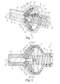
- FIGS. 1 to 4 show a pedal force generating device 1 according to the invention, wherein the FIG. 1 shows the pedal force generating device in a perspective view in an unactuated state.
- the FIGS. 2 to 4 show the pedal force generating device 1 in an unactuated state, in a partially actuated state or in a substantially fully actuated state.
- the pedal actuating device 1 has a housing 2, in which a piston 3 is received longitudinally displaceable.
- the piston 3 can be displaced axially displaceably in a channel 4 of the housing 2, wherein the housing has at one end of the piston an opening 5 through which a piston rod can engage in the housing 2 and the piston 3 can act and relocate.
- the housing 2 is advantageously made up of at least two housing elements 6, 7 which are connected to one another.
- Each housing part is formed with a cylindrical part and an approximately funnel-shaped widening part, wherein the housing parts 6, 7 touching the funnel-shaped widening part and are interconnected.
- a first force accumulator 8 is arranged, which is axially supported on the housing 2 in the region of the housing part 7 and there in the cylindrical region at one of its ends.
- the other end of the energy accumulator 8 is supported on a support plate 9, which is connected to the piston 3.
- the support plate has a neck which engages in a receptacle of the piston 3.
- the support plate 9 has an annular edge, which is offset from the central surface back. As a result, the central surface can engage in an opening of the windings of the first energy accumulator and center the energy accumulator.
- the first energy accumulator 8 is arranged coaxially to the piston 3 and the piston 3 is supported on a first end 11 of the first energy accumulator 8, wherein the first energy accumulator 8 is supported at its second end 12 on the housing 2.
- second force accumulators 10 are further arranged, which are supported at one of its ends on the housing 2 and supported at its other end to the piston 3.
- a second energy store 10 is advantageous, or at least two second energy stores 10 are pivotably arranged in the housing 2, wherein the at least one second energy store 10 is supported on the housing at its first end 13 and is supported on the piston at its second end 14.
- two second energy storage 10 are arranged, which are opposite to the displacement axis 15 of the piston 3.
- four second power storage 10 are arranged, wherein two times two each second energy storage 10 with respect to the displacement axis 15 of the piston 3 are opposite.
- the four second energy accumulators 10 are arranged in the housing 2 such that they are arranged in the shape of a cross in the viewing direction of the displacement axis 15 of the piston 3.
- the arrangement does not have to be cross-shaped, but can also be chosen elsewhere.
- the second energy storage 10 have at their end portions 13, 14 joint shoes 16, by means of which they are articulated to the housing 2 and the piston 3.
- the hinge elements are used for the articulated receiving and holding the joint shoes 16 on the housing 2 and the retaining plate 18 serve to connect to the energy storage.
- the articulated shoes engage with their holding plates 18 in recesses of the second force accumulator 10.
- FIG. 1 and in FIG. 2 a state is shown in which the piston 3 is in an unactuated position.
- the energy storage are preferably supported with bias on the piston and tense it in the unactuated starting position.
- the piston is displaced to the right and is displaced counter to the restoring force of the energy accumulators 8, 10.
- the characteristic of the energy storage device is usually linear, wherein the characteristic of the energy storage is modulated due to the pivoting of the energy storage.
- the restoring force of the second energy storage decreases on the piston with the piston displacement.
- FIG. 3 the position of the piston is shown in which the restoring force of the second energy storage 10 is zero.
- FIG. 4 The restoring force of the second energy storage converts their sign and the second energy storage support the further displacement of the piston 3.
- FIG. 2 shows the one end position of the piston 3 and the FIG. 4 shows the second end position of the piston 3 in the housing 2, wherein the piston between these two end positions is displaced.
Abstract
Die Erfindung betrifft eine Pedalkrafterzeugungsvorrichtung mit einem in einem Gehäuse verlagerbar angeordneten Kolben, wobei der Kolben im Gehäuse zwischen einer ersten Endstellung und einer zweiten Endstellung verlagerbar ist, wobei in dem Gehäuse ein erster Kraftspeicher angeordnet ist, wobei der Kolben entgegen der Rückstellkraft des ersten Kraftspeichers verlagerbar ist, und wobei auf den Kolben zumindest ein weiterer zweiter Kraftspeicher einwirkt, welcher seine Kraftwirkung auf den Kolben zwischen der ersten Endstellung und der zweiten Endstellung wechselt.The invention relates to a pedal force generating device with a displaceably arranged in a housing piston, wherein the piston in the housing between a first end position and a second end position is displaceable, wherein in the housing, a first energy storage is arranged, wherein the piston against the restoring force of the first energy storage displaced is, and wherein acts on the piston at least one further second energy storage, which changes its force on the piston between the first end position and the second end position.
Description
Die Erfindung betrifft eine Pedalkrafterzeugungsvorrichtung, insbesondere für ein Kupplungspedal oder ein Bremspedal für ein Kraftfahrzeug, sowie beispielsweise auch für Simulatoren, in welchen ein Kupplungspedal zum Einsatz kommt.The invention relates to a pedal force generating device, in particular for a clutch pedal or a brake pedal for a motor vehicle, as well as, for example, for simulators in which a clutch pedal is used.
Kupplungen in Kraftfahrzeugen werden mit einem Kupplungspedal durch den Fahrer betätigt. Dabei muss der Fahrer mit dem Fuß das Pedal entgegen der Rückstellkraft der Elastizitäten und Federkräfte im Betätigungssystem und in der Kupplung betätigen. Die Betätigungskraft hat dabei einen typischen vom Fahrer erwarteten Kraftverlauf. Wird die Kupplung elektronisch gesteuert betätigt, wobei ein Aktuator die Betätigung der Kupplung übernimmt, kann dennoch ein Pedal für den Fahrer vorgesehen sein, um dem Fahrer die Steuerung der Betätigung der Kupplung zu überlassen, obwohl keine direkte mechanische Verbindung oder Druckmittelverbindung zwischen dem Pedal und der Kupplung mehr vorliegt. Damit der Fahrer aber die für die tatsächliche Kupplungsbetätigung resultierende Rückstellkraft spürt, sind Pedalkrafterzeugungsvorrichtungen bekannt geworden, die eine Pedalkraft als Kupplungsrückstellkraft simulieren.Clutches in motor vehicles are operated with a clutch pedal by the driver. In doing so, the driver must use the foot to press the pedal against the restoring force of the elasticities and spring forces in the actuation system and in the clutch. The actuating force has a typical force curve expected by the driver. If the clutch operated electronically controlled, with an actuator takes over the actuation of the clutch, but a pedal for the driver may be provided to allow the driver to control the operation of the clutch, although no direct mechanical connection or fluid connection between the pedal and the Clutch is more present. However, in order for the driver to feel the restoring force resulting from the actual clutch operation, pedal force generating devices have become known which simulate a pedaling force as the clutch restoring force.
In der
Auch sind Pedalkrafterzeugungsvorrichtungen bekannt geworden, welche die tatsächliche Pedalkraft modulieren, um die resultierende Pedalkraft an die Erwartungen des Fahrers besser anzupassen. Solche Pedalkrafterzeugungsvorrichtungen sind beispielsweise durch die
Es ist die Aufgabe der Erfindung, eine Pedalkrafterzeugungsvorrichtung zu schaffen, welche einfach und klein aufgebaut ist und dennoch eine realistische Gegenkraft für ein zu betätigendes Pedal erzeugt.It is the object of the invention to provide a pedal force generating device which is simple and small and yet generates a realistic counterforce for a pedal to be operated.
Die Aufgabe der Erfindung wird mit den Merkmalen von Anspruch 1 gelöst.The object of the invention is achieved with the features of
Ein Ausführungsbeispiel der Erfindung betrifft eine Pedalkrafterzeugungsvorrichtung mit einem in einem Gehäuse verlagerbar angeordneten Kolben, wobei der Kolben im Gehäuse zwischen einer ersten Endstellung und einer zweiten Endstellung verlagerbar ist, wobei in dem Gehäuse ein erster Kraftspeicher angeordnet ist, wobei der Kolben entgegen der Rückstellkraft des ersten Kraftspeichers verlagerbar ist, und wobei auf den Kolben zumindest ein weiterer zweiter Kraftspeicher einwirkt, welcher seine Kraftwirkung auf den Kolben zwischen der ersten Endstellung und der zweiten Endstellung wechselt. Dadurch wird erreicht, dass der Kolben über den gesamten Betätigungsweg entgegen der Rückstellkraft des ersten Kraftspeichers verlagerbar ist, wobei über einen Teil des Betätigungswegs der zumindest eine zweite Kraftspeicher die Kraftwirkung auf den Kolben erhöht und über einen weiteren Teil des Betätigungswegs die Kraftwirkung auf den Kolben reduziert. Dadurch wird eine Modulation der Betätigungskraft erreicht, die der gewünschten Betätigungskraft entspricht.An embodiment of the invention relates to a pedal force generating device with a displaceably arranged in a housing piston, wherein the piston is displaceable in the housing between a first end position and a second end position, wherein in the housing, a first energy storage is arranged, wherein the piston counter to the restoring force of the first Power accumulator is displaced, and wherein acts on the piston at least one further second energy accumulator, which changes its force on the piston between the first end position and the second end position. This ensures that the piston is displaceable over the entire actuation path against the restoring force of the first energy accumulator, wherein over a portion of the actuation travel of the at least one second energy accumulator increases the force on the piston and reduces the force on the piston over a further part of the actuation path , As a result, a modulation of the actuating force is achieved, which corresponds to the desired operating force.
Bei einem Ausführungsbeispiel ist es vorteilhaft, wenn der erste Kraftspeicher koaxial zum Kolben angeordnet ist und der Kolben sich an einem ersten Ende des ersten Kraftspeichers abstützt, wobei sich der erste Kraftspeicher an seinem zweiten Ende am Gehäuse abstützt. So wird eine Anordnung des ersten Kraftspeichers erreicht, der koaxial zum Kolben angeordnet ist, was platzsparend ist und eine im Wesentlichen lineare Kennlinie bewirkt.In one embodiment, it is advantageous if the first energy accumulator is arranged coaxially to the piston and the piston is supported on a first end of the first energy accumulator, wherein the first energy accumulator is supported at its second end on the housing. Thus, an arrangement of the first force accumulator is achieved, which is arranged coaxially to the piston, which saves space and causes a substantially linear characteristic.
Auch ist es vorteilhaft, wenn der zumindest eine zweite Kraftspeicher verschwenkbar im Gehäuse angeordnet ist, wobei der zweite Kraftspeicher an seinem ersten Ende am Gehäuse abgestützt ist und an seinem zweiten Ende am Kolben abgestützt ist. Dadurch kann eine Federkennlinie erzeugt werden, die ihr Vorzeichen wechselt, weil der Kraftspeicher verschwenken kann.It is also advantageous if the at least one second energy store is pivotably arranged in the housing, wherein the second energy accumulator is supported at its first end on the housing and is supported at its second end on the piston. As a result, a spring characteristic can be generated, which changes its sign, because the energy storage can pivot.
Auch ist es zweckmäßig, wenn zwei zweite Kraftspeicher angeordnet sind, die sich bezüglich der Verschiebeachse des Kolbens gegenüber liegen. Dadurch kann die Federkraft des bzw. der zweiten Kraftspeicher verstärkt werden.It is also expedient if two second force accumulators are arranged, which lie opposite one another with respect to the displacement axis of the piston. As a result, the spring force of the second energy storage device or be strengthened.
Erfindungsgemäß ist es vorteilhaft, wenn vier zweite Kraftspeicher angeordnet sind, wobei sich zwei mal jeweils zwei zweite Kraftspeicher bezüglich der Verschiebeachse des Kolbens gegenüber liegen.According to the invention, it is advantageous if four second force accumulators are arranged, wherein two times each two second force accumulators are located opposite to the displacement axis of the piston.
Dazu ist es vorteilhaft, wenn die vier zweite Kraftspeicher im Gehäuse angeordnet sind, die in Blickrichtung der Verschiebeachse des Kolbens betrachtet kreuzförmig angeordnet sind.For this purpose, it is advantageous if the four second energy accumulators are arranged in the housing, which are viewed in the direction of the displacement axis of the piston arranged in a cross shape.
Besonders vorteilhaft ist es, wenn die zweiten Kraftspeicher an ihren Endbereichen Gelenkschuhe aufweisen, mittels welchen sie am Gehäuse und am Kolben gelenkig gelagert sind. Dadurch ist der Verschleiß aufgrund der Verschwenkung reduziert bzw. minimiert.It is particularly advantageous if the second force accumulators have articulated shoes at their end regions, by means of which they are articulated on the housing and on the piston. As a result, the wear due to the pivoting is reduced or minimized.
Erfindungsgemäß ist es vorteilhaft, wenn die Gelenkschuhe in Ausnehmungen der zweiten Kraftspeicher eingreifen. Dadurch kann der Gelenkschuh sicher an dem Kraftspeicher befestigt werden.According to the invention, it is advantageous if the articulated shoes engage in recesses of the second energy accumulator. Thereby, the joint shoe can be securely attached to the energy storage.
Auch ist es vorteilhaft, wenn der erste Kraftspeicher sich an dem Kolben über einen Abstützteller abstützt. Dadurch kann die Abstützung einfach auf den Durchmesser des Kraftspeichers angepasst werden, auch wenn der Kolben einen unterschiedlichen Durchmesser aufweist.It is also advantageous if the first energy accumulator is supported on the piston via a support plate. As a result, the support can be easily adapted to the diameter of the energy accumulator, even if the piston has a different diameter.
Zur Betätigung des Kolbens ist es zweckmäßig, wenn der Kolben mit einer Kolbenstange verbindbar ist, welche in das Gehäuse hinein ragt.For actuating the piston, it is expedient if the piston can be connected to a piston rod which projects into the housing.
Die vorliegende Erfindung wird nachfolgend anhand bevorzugter Ausführungsbeispiele in Verbindung mit den zugehörigen Figuren näher erläutert:The present invention will be explained in more detail below with reference to preferred exemplary embodiments in conjunction with the associated figures:
Dabei zeigen:
Figur 1- eine schematische perspektivische Ansicht einer Pedalkrafterzeugungsvorrichtung,
Figur 2- eine schematische Ansicht einer Pedalkrafterzeugungsvorrichtung in einem unbetätigten Zustand,
Figur 3- eine schematische Ansicht der Pedalkrafterzeugungsvorrichtung in einem einem teilbetätigten Zustand, und
Figur 4- eine schematische Ansicht der Pedalkrafterzeugungsvorrichtung in einem im Wesentlichen vollständig betätigten Zustand.
- FIG. 1
- a schematic perspective view of a pedal force generating device,
- FIG. 2
- a schematic view of a pedal force generating device in an unactuated state,
- FIG. 3
- a schematic view of the pedal force generating device in a partially actuated state, and
- FIG. 4
- a schematic view of the pedal force generating device in a substantially fully actuated state.
Die
Die Pedalbetätigungsvorrichtung 1 weist ein Gehäuse 2 auf, in welchem ein Kolben 3 längsverschieblich aufgenommen ist. Der Kolben 3 kann dabei in einem Kanal 4 des Gehäuses 2 axial verschieblich verlagert werden, wobei das Gehäuse an einem Ende des Kolbens eine Öffnung 5 aufweist, durch welche eine Kolbenstange in das Gehäuse 2 eingreifen kann und den Kolben 3 beaufschlagen und verlagern kann.The pedal actuating
Das Gehäuse 2 ist vorteilhaft aus zumindest zwei Gehäuseelementen 6, 7 aufgebaut, die miteinander verbunden sind. Jedes Gehäuseteil ist dabei mit einem zylindrischen Teil und einem sich etwa trichterförmig erweiternden Teil ausgebildet, wobei sich die Gehäuseteile 6, 7 am trichterförmig erweiternden Teil berühren und miteinander verbunden sind.The
Im Gehäuse 2 ist ein erster Kraftspeicher 8 angeordnet, welcher sich an dem Gehäuse 2 im Bereich des Gehäuseteils 7 und dort im zylindrischen Bereich an einem seiner Enden axial abstützt. Das andere Ende des Kraftspeichers 8 stützt sich an einem Abstützteller 9 ab, welcher mit dem Kolben 3 verbunden ist. Dazu weist der Abstützteller einen Hals auf, welcher in eine Aufnahme des Kolbens 3 eingreift. Der Abstützteller 9 weist einen ringförmigen Rand auf, der gegenüber der zentralen Fläche zurück versetzt ist. Dadurch kann die zentrale Fläche in eine Öffnung der Windungen des ersten Kraftspeichers eingreifen und den Kraftspeicher zentrieren. Der erste Kraftspeicher 8 ist koaxial zum Kolben 3 angeordnet und der Kolben 3 stützt sich an einem ersten Ende 11 des ersten Kraftspeichers 8 ab, wobei sich der erste Kraftspeicher 8 an seinem zweiten Ende 12 am Gehäuse 2 abstützt.In the
Im Gehäuse sind weiterhin zweite Kraftspeicher 10 angeordnet, welche sich an einem ihrer Enden am Gehäuse 2 abstützen und an ihrem anderen Ende an dem Kolben 3 abstützen. In den Figuren sind jeweils nur Teile der zweiten Kraftspeicher zu erkennen. Erfindungsgemäß ist vorteilhaft ein zweiter Kraftspeicher 10 oder es sind zumindest zwei zweite Kraftspeicher 10 verschwenkbar im Gehäuse 2 angeordnet, wobei der zumindest eine zweite Kraftspeicher 10 sich an seinem ersten Ende 13 am Gehäuse abstützt und an seinem zweiten Ende 14 sich am Kolben abstützt. Bevorzugt sind zwei zweite Kraftspeicher 10 angeordnet, die sich bezüglich der Verschiebeachse 15 des Kolbens 3 gegenüber liegen. Bei einem weiteren Ausführungsbeispiel sind vier zweite Kraftspeicher 10 angeordnet sind, wobei sich zwei mal jeweils zwei zweite Kraftspeicher 10 bezüglich der Verschiebeachse 15 des Kolbens 3 gegenüber liegen. Dabei sind die vier zweiten Kraftspeicher 10 im Gehäuse 2 derart angeordnet, dass sie in Blickrichtung der Verschiebeachse 15 des Kolbens 3 betrachtet kreuzförmig angeordnet sind. Die Anordnung muss jedoch nicht kreuzförmig sein, sondern kann auch anderweitig gewählt werden. Es kann auch eine ungerade Zahl zusätzlicher Kraftspeicher vorhanden sein, die zum Beispiel sternförmig angeordnet sind. Günstig ist dabei, wenn der Kolben 3 nicht auf eine bestimmte Seite gedrückt wird, was jedoch am einfachsten durch eine gegenüberliegende Anordnung der zusätzlichen Kraftspeicher erreicht wird.In the housing,
Die zweiten Kraftspeicher 10 weisen an ihren Endbereichen 13, 14 Gelenkschuhe 16 auf, mittels welchen sie am Gehäuse 2 und am Kolben 3 gelenkig gelagert sind. Dazu weisen die Gelenkschuhe Gelenkelemente 17 und Halteteller 18 auf. Die Gelenkelemente dienen der gelenkigen Aufnahme und Halterung der Gelenkschuhe 16 am Gehäuse 2 und die Halteteller 18 dienen der Verbindung mit dem Kraftspeicher. Dazu greifen die Gelenkschuhe mit ihren Haltetellern 18 in Ausnehmungen der zweiten Kraftspeicher 10 ein.The
In
In
- 11
- PedalkrafterzeugungsvorrichtungPedal power generation device
- 22
- Gehäusecasing
- 33
- Kolbenpiston
- 44
- Kanalchannel
- 55
- Öffnungopening
- 66
- Gehäuseelementhousing element
- 77
- Gehäuseelementhousing element
- 88th
- erster Kraftspeicherfirst energy storage
- 99
- Abstütztellersupporting pads
- 1010
- zweiter Kraftspeichersecond energy storage
- 1111
- EndeThe End
- 1212
- EndeThe End
- 1313
- EndeThe End
- 1414
- EndeThe End
- 1515
- Verschiebeachsedisplacement axis
- 1616
- Gelenkschuhjoint shoe
- 1717
- Gelenkelementjoint element
- 1818
- Haltetellerretaining plate
Claims (10)
Applications Claiming Priority (1)
| Application Number | Priority Date | Filing Date | Title |
|---|---|---|---|
| DE102014204724 | 2014-03-14 |
Publications (4)
| Publication Number | Publication Date |
|---|---|
| EP2919090A2 true EP2919090A2 (en) | 2015-09-16 |
| EP2919090A3 EP2919090A3 (en) | 2016-07-27 |
| EP2919090B1 EP2919090B1 (en) | 2018-07-11 |
| EP2919090B2 EP2919090B2 (en) | 2022-04-20 |
Family
ID=52484368
Family Applications (1)
| Application Number | Title | Priority Date | Filing Date |
|---|---|---|---|
| EP15155521.6A Active EP2919090B2 (en) | 2014-03-14 | 2015-02-18 | Pedal force creation device |
Country Status (2)
| Country | Link |
|---|---|
| EP (1) | EP2919090B2 (en) |
| DE (1) | DE102015202875A1 (en) |
Cited By (3)
| Publication number | Priority date | Publication date | Assignee | Title |
|---|---|---|---|---|
| ITUB20156277A1 (en) * | 2015-12-03 | 2017-06-03 | Plastic Components And Modules Automotive S P A | Electronic clutch pedal for vehicle. |
| CN107585024A (en) * | 2016-07-06 | 2018-01-16 | Zf腓特烈斯哈芬股份公司 | Pedal force simulated assembly and motor vehicle |
| EP3213168B1 (en) | 2014-10-29 | 2018-07-04 | Schaeffler Technologies AG & Co. KG | Device for simulating a force on an actuation element of a vehicle, preferably a pedal simulator |
Families Citing this family (7)
| Publication number | Priority date | Publication date | Assignee | Title |
|---|---|---|---|---|
| DE102015214974A1 (en) | 2015-08-06 | 2017-02-09 | Schaeffler Technologies AG & Co. KG | Device for power simulation on an actuating element of a vehicle |
| DE102016212354A1 (en) * | 2016-07-06 | 2018-01-11 | Zf Friedrichshafen Ag | Pedal force simulation arrangement and motor vehicle |
| DE102016212356A1 (en) * | 2016-07-06 | 2018-01-11 | Zf Friedrichshafen Ag | Pedal force simulation arrangement and motor vehicle |
| DE102016123735A1 (en) | 2016-12-08 | 2018-06-14 | Schaeffler Technologies AG & Co. KG | Pedal force simulator with two serially arranged springs with mutually angled effective axes and e-clutch system |
| DE102017204346A1 (en) | 2017-03-15 | 2018-09-20 | Zf Friedrichshafen Ag | Pedal force simulation arrangement and motor vehicle |
| DE102017204343A1 (en) * | 2017-03-15 | 2018-09-20 | Zf Friedrichshafen Ag | Pedal force simulation arrangement and motor vehicle |
| DE102017204348A1 (en) | 2017-03-15 | 2018-09-20 | Zf Friedrichshafen Ag | Pedal force simulation arrangement and motor vehicle |
Citations (3)
| Publication number | Priority date | Publication date | Assignee | Title |
|---|---|---|---|---|
| DE4327881C1 (en) | 1993-08-19 | 1994-07-21 | Daimler Benz Ag | Clutch control for hybrid transmission vehicle |
| DE10360784A1 (en) | 2003-12-23 | 2005-08-04 | Audi Ag | Apparatus for engaging and disengaging the clutch of a vehicle whereby the force of the clutch follows a curve and is greater on engaging than disengaging |
| DE102008061569A1 (en) | 2007-12-19 | 2009-06-25 | Luk Lamellen Und Kupplungsbau Beteiligungs Kg | Clutch operating system for friction clutch in motor vehicle, has profile unit having two opposite profile characteristics line arranged along profile unit, which pressurizes two rollers or sliding body |
Family Cites Families (7)
| Publication number | Priority date | Publication date | Assignee | Title |
|---|---|---|---|---|
| GB516037A (en) † | 1938-07-09 | 1939-12-20 | Bendix Ltd | Improvements in or relating to mechanical servo mechanism |
| DE1285817B (en) † | 1966-06-20 | 1968-12-19 | Schroeter Hans O | Working cylinder with spring accumulator, especially for hydraulic brakes |
| GB8626480D0 (en) † | 1986-11-05 | 1986-12-03 | Dewandre Co Ltd C | Clutch booster |
| DE10192652D2 (en) † | 2000-07-07 | 2003-06-18 | Rohs Voigt Patentverwertungsge | Master cylinder |
| FR2848518B1 (en) * | 2002-12-13 | 2006-01-13 | Renault Sa | PASSIVE SYSTEM FOR REINSTALLING EFFORT ON A PEDAL, IN PARTICULAR A CLUTCH PEDAL FOR A MOTOR VEHICLE |
| US20070193400A1 (en) * | 2006-01-27 | 2007-08-23 | Kline Scott A | Clutch pedal mechanism with variable resistive force |
| EP2896539B1 (en) * | 2013-12-17 | 2019-10-09 | Schaeffler Technologies AG & Co. KG | System for simulating pedal force, in particular for a clutch actuation system |
-
2015
- 2015-02-18 EP EP15155521.6A patent/EP2919090B2/en active Active
- 2015-02-18 DE DE102015202875.5A patent/DE102015202875A1/en not_active Withdrawn
Patent Citations (3)
| Publication number | Priority date | Publication date | Assignee | Title |
|---|---|---|---|---|
| DE4327881C1 (en) | 1993-08-19 | 1994-07-21 | Daimler Benz Ag | Clutch control for hybrid transmission vehicle |
| DE10360784A1 (en) | 2003-12-23 | 2005-08-04 | Audi Ag | Apparatus for engaging and disengaging the clutch of a vehicle whereby the force of the clutch follows a curve and is greater on engaging than disengaging |
| DE102008061569A1 (en) | 2007-12-19 | 2009-06-25 | Luk Lamellen Und Kupplungsbau Beteiligungs Kg | Clutch operating system for friction clutch in motor vehicle, has profile unit having two opposite profile characteristics line arranged along profile unit, which pressurizes two rollers or sliding body |
Cited By (4)
| Publication number | Priority date | Publication date | Assignee | Title |
|---|---|---|---|---|
| EP3213168B1 (en) | 2014-10-29 | 2018-07-04 | Schaeffler Technologies AG & Co. KG | Device for simulating a force on an actuation element of a vehicle, preferably a pedal simulator |
| EP3213168B2 (en) † | 2014-10-29 | 2021-07-07 | Schaeffler Technologies AG & Co. KG | Device for simulating a force on an actuation element of a vehicle, in the form of a pedal simulator |
| ITUB20156277A1 (en) * | 2015-12-03 | 2017-06-03 | Plastic Components And Modules Automotive S P A | Electronic clutch pedal for vehicle. |
| CN107585024A (en) * | 2016-07-06 | 2018-01-16 | Zf腓特烈斯哈芬股份公司 | Pedal force simulated assembly and motor vehicle |
Also Published As
| Publication number | Publication date |
|---|---|
| EP2919090B2 (en) | 2022-04-20 |
| EP2919090B1 (en) | 2018-07-11 |
| DE102015202875A1 (en) | 2015-09-17 |
| EP2919090A3 (en) | 2016-07-27 |
Similar Documents
| Publication | Publication Date | Title |
|---|---|---|
| EP2919090B1 (en) | Pedal force creation device | |
| DE102019101646A1 (en) | Pedal emulator for a vehicle | |
| DE102011051863A9 (en) | Switching device for a manual transmission | |
| DE202006021191U1 (en) | Adjustable steering column for a motor vehicle | |
| EP2896539A2 (en) | System for simulating pedal force, in particular for a clutch actuation system | |
| DE102012111315A1 (en) | Pedal system for generating a force curve with hysteresis | |
| EP2924535A2 (en) | Joystick with intrinsically secure force feedback | |
| DE102010003822A1 (en) | Brake booster coupling device | |
| DE102008058265A1 (en) | Disc brake and brake pad assembly for this | |
| DE102015110186A1 (en) | Actuator for a clutch, in particular a motor vehicle | |
| DE102011052226A1 (en) | Clutch pedal switch for a vehicle | |
| DE102014118573A1 (en) | Pedal device with controllable actuating force | |
| DE102005035067A1 (en) | Arrangement for operating of clutch in drive train of motor vehicle has spring connected by first fastening point to means which describe curved path depending upon position of clutch pedal, and by second fastening point to clutch pedal | |
| DE202016106697U1 (en) | Electronic clutch pedal for a vehicle | |
| DE202011002608U1 (en) | tripod head | |
| DE102011076127A1 (en) | Motorized fluid storage device for brake system of motor vehicle, has storage chamber, whose inner volume is partially filled with fluid, where piston molded part is adjusted along adjustable axis | |
| EP1659017A1 (en) | Apparatus for reduction of the pedal force | |
| DE102009042806A1 (en) | Pedal arrangement for manual actuation of shifting device of motor vehicle clutch, has spring unit whose fastening axle and spring axle are diverged from each other, where spring unit comprises torsion springs connected in series | |
| EP2927064B1 (en) | Pedal force creation device | |
| DE102007018029B3 (en) | tripod head | |
| DE602004005063T2 (en) | DOUBLE COUPLING, ESPECIALLY FOR A MOTOR VEHICLE | |
| DE102018202470A1 (en) | Accelerator pedal, in particular for a motor vehicle | |
| DE112007002890T5 (en) | Steering device with a ball screw | |
| DE102014203271A1 (en) | Actuation device for a clutch | |
| DE102015214974A1 (en) | Device for power simulation on an actuating element of a vehicle |
Legal Events
| Date | Code | Title | Description |
|---|---|---|---|
| PUAI | Public reference made under article 153(3) epc to a published international application that has entered the european phase |
Free format text: ORIGINAL CODE: 0009012 |
|
| AK | Designated contracting states |
Kind code of ref document: A2 Designated state(s): AL AT BE BG CH CY CZ DE DK EE ES FI FR GB GR HR HU IE IS IT LI LT LU LV MC MK MT NL NO PL PT RO RS SE SI SK SM TR |
|
| AX | Request for extension of the european patent |
Extension state: BA ME |
|
| PUAL | Search report despatched |
Free format text: ORIGINAL CODE: 0009013 |
|
| AK | Designated contracting states |
Kind code of ref document: A3 Designated state(s): AL AT BE BG CH CY CZ DE DK EE ES FI FR GB GR HR HU IE IS IT LI LT LU LV MC MK MT NL NO PL PT RO RS SE SI SK SM TR |
|
| AX | Request for extension of the european patent |
Extension state: BA ME |
|
| RIC1 | Information provided on ipc code assigned before grant |
Ipc: G05G 5/03 20080401ALI20160617BHEP Ipc: G05G 1/30 20080401ALN20160617BHEP Ipc: G05G 5/05 20060101AFI20160617BHEP Ipc: B60K 26/02 20060101ALI20160617BHEP |
|
| STAA | Information on the status of an ep patent application or granted ep patent |
Free format text: STATUS: REQUEST FOR EXAMINATION WAS MADE |
|
| 17P | Request for examination filed |
Effective date: 20170127 |
|
| RBV | Designated contracting states (corrected) |
Designated state(s): AL AT BE BG CH CY CZ DE DK EE ES FI FR GB GR HR HU IE IS IT LI LT LU LV MC MK MT NL NO PL PT RO RS SE SI SK SM TR |
|
| GRAP | Despatch of communication of intention to grant a patent |
Free format text: ORIGINAL CODE: EPIDOSNIGR1 |
|
| STAA | Information on the status of an ep patent application or granted ep patent |
Free format text: STATUS: GRANT OF PATENT IS INTENDED |
|
| RIC1 | Information provided on ipc code assigned before grant |
Ipc: G05G 5/03 20080401ALI20180129BHEP Ipc: G05G 1/30 20080401ALN20180129BHEP Ipc: G05G 5/05 20060101AFI20180129BHEP Ipc: B60K 26/02 20060101ALI20180129BHEP |
|
| RIC1 | Information provided on ipc code assigned before grant |
Ipc: G05G 1/30 20080401ALN20180205BHEP Ipc: G05G 5/03 20080401ALI20180205BHEP Ipc: G05G 5/05 20060101AFI20180205BHEP Ipc: B60K 26/02 20060101ALI20180205BHEP |
|
| INTG | Intention to grant announced |
Effective date: 20180220 |
|
| GRAS | Grant fee paid |
Free format text: ORIGINAL CODE: EPIDOSNIGR3 |
|
| GRAA | (expected) grant |
Free format text: ORIGINAL CODE: 0009210 |
|
| STAA | Information on the status of an ep patent application or granted ep patent |
Free format text: STATUS: THE PATENT HAS BEEN GRANTED |
|
| AK | Designated contracting states |
Kind code of ref document: B1 Designated state(s): AL AT BE BG CH CY CZ DE DK EE ES FI FR GB GR HR HU IE IS IT LI LT LU LV MC MK MT NL NO PL PT RO RS SE SI SK SM TR |
|
| REG | Reference to a national code |
Ref country code: GB Ref legal event code: FG4D Free format text: NOT ENGLISH |
|
| REG | Reference to a national code |
Ref country code: CH Ref legal event code: EP |
|
| REG | Reference to a national code |
Ref country code: AT Ref legal event code: REF Ref document number: 1017553 Country of ref document: AT Kind code of ref document: T Effective date: 20180715 |
|
| REG | Reference to a national code |
Ref country code: IE Ref legal event code: FG4D Free format text: LANGUAGE OF EP DOCUMENT: GERMAN |
|
| REG | Reference to a national code |
Ref country code: DE Ref legal event code: R096 Ref document number: 502015004981 Country of ref document: DE |
|
| REG | Reference to a national code |
Ref country code: NL Ref legal event code: MP Effective date: 20180711 |
|
| REG | Reference to a national code |
Ref country code: LT Ref legal event code: MG4D |
|
| PG25 | Lapsed in a contracting state [announced via postgrant information from national office to epo] |
Ref country code: NL Free format text: LAPSE BECAUSE OF FAILURE TO SUBMIT A TRANSLATION OF THE DESCRIPTION OR TO PAY THE FEE WITHIN THE PRESCRIBED TIME-LIMIT Effective date: 20180711 |
|
| PG25 | Lapsed in a contracting state [announced via postgrant information from national office to epo] |
Ref country code: SE Free format text: LAPSE BECAUSE OF FAILURE TO SUBMIT A TRANSLATION OF THE DESCRIPTION OR TO PAY THE FEE WITHIN THE PRESCRIBED TIME-LIMIT Effective date: 20180711 Ref country code: GR Free format text: LAPSE BECAUSE OF FAILURE TO SUBMIT A TRANSLATION OF THE DESCRIPTION OR TO PAY THE FEE WITHIN THE PRESCRIBED TIME-LIMIT Effective date: 20181012 Ref country code: RS Free format text: LAPSE BECAUSE OF FAILURE TO SUBMIT A TRANSLATION OF THE DESCRIPTION OR TO PAY THE FEE WITHIN THE PRESCRIBED TIME-LIMIT Effective date: 20180711 Ref country code: BG Free format text: LAPSE BECAUSE OF FAILURE TO SUBMIT A TRANSLATION OF THE DESCRIPTION OR TO PAY THE FEE WITHIN THE PRESCRIBED TIME-LIMIT Effective date: 20181011 Ref country code: LT Free format text: LAPSE BECAUSE OF FAILURE TO SUBMIT A TRANSLATION OF THE DESCRIPTION OR TO PAY THE FEE WITHIN THE PRESCRIBED TIME-LIMIT Effective date: 20180711 Ref country code: PL Free format text: LAPSE BECAUSE OF FAILURE TO SUBMIT A TRANSLATION OF THE DESCRIPTION OR TO PAY THE FEE WITHIN THE PRESCRIBED TIME-LIMIT Effective date: 20180711 Ref country code: FI Free format text: LAPSE BECAUSE OF FAILURE TO SUBMIT A TRANSLATION OF THE DESCRIPTION OR TO PAY THE FEE WITHIN THE PRESCRIBED TIME-LIMIT Effective date: 20180711 Ref country code: NO Free format text: LAPSE BECAUSE OF FAILURE TO SUBMIT A TRANSLATION OF THE DESCRIPTION OR TO PAY THE FEE WITHIN THE PRESCRIBED TIME-LIMIT Effective date: 20181011 Ref country code: IS Free format text: LAPSE BECAUSE OF FAILURE TO SUBMIT A TRANSLATION OF THE DESCRIPTION OR TO PAY THE FEE WITHIN THE PRESCRIBED TIME-LIMIT Effective date: 20181111 |
|
| REG | Reference to a national code |
Ref country code: CH Ref legal event code: PK Free format text: BERICHTIGUNGEN |
|
| RIC2 | Information provided on ipc code assigned after grant |
Ipc: B60K 26/02 20060101ALI20180205BHEP Ipc: G05G 5/05 20060101AFI20180205BHEP Ipc: G05G 1/30 20080401ALN20180205BHEP Ipc: G05G 5/03 20080401ALI20180205BHEP |
|
| PG25 | Lapsed in a contracting state [announced via postgrant information from national office to epo] |
Ref country code: LV Free format text: LAPSE BECAUSE OF FAILURE TO SUBMIT A TRANSLATION OF THE DESCRIPTION OR TO PAY THE FEE WITHIN THE PRESCRIBED TIME-LIMIT Effective date: 20180711 Ref country code: HR Free format text: LAPSE BECAUSE OF FAILURE TO SUBMIT A TRANSLATION OF THE DESCRIPTION OR TO PAY THE FEE WITHIN THE PRESCRIBED TIME-LIMIT Effective date: 20180711 Ref country code: ES Free format text: LAPSE BECAUSE OF FAILURE TO SUBMIT A TRANSLATION OF THE DESCRIPTION OR TO PAY THE FEE WITHIN THE PRESCRIBED TIME-LIMIT Effective date: 20180711 Ref country code: AL Free format text: LAPSE BECAUSE OF FAILURE TO SUBMIT A TRANSLATION OF THE DESCRIPTION OR TO PAY THE FEE WITHIN THE PRESCRIBED TIME-LIMIT Effective date: 20180711 |
|
| REG | Reference to a national code |
Ref country code: DE Ref legal event code: R026 Ref document number: 502015004981 Country of ref document: DE |
|
| PLBI | Opposition filed |
Free format text: ORIGINAL CODE: 0009260 |
|
| PLAX | Notice of opposition and request to file observation + time limit sent |
Free format text: ORIGINAL CODE: EPIDOSNOBS2 |
|
| PG25 | Lapsed in a contracting state [announced via postgrant information from national office to epo] |
Ref country code: RO Free format text: LAPSE BECAUSE OF FAILURE TO SUBMIT A TRANSLATION OF THE DESCRIPTION OR TO PAY THE FEE WITHIN THE PRESCRIBED TIME-LIMIT Effective date: 20180711 Ref country code: CZ Free format text: LAPSE BECAUSE OF FAILURE TO SUBMIT A TRANSLATION OF THE DESCRIPTION OR TO PAY THE FEE WITHIN THE PRESCRIBED TIME-LIMIT Effective date: 20180711 Ref country code: IT Free format text: LAPSE BECAUSE OF FAILURE TO SUBMIT A TRANSLATION OF THE DESCRIPTION OR TO PAY THE FEE WITHIN THE PRESCRIBED TIME-LIMIT Effective date: 20180711 Ref country code: EE Free format text: LAPSE BECAUSE OF FAILURE TO SUBMIT A TRANSLATION OF THE DESCRIPTION OR TO PAY THE FEE WITHIN THE PRESCRIBED TIME-LIMIT Effective date: 20180711 |
|
| 26 | Opposition filed |
Opponent name: ZF FRIEDRICHSHAFEN AG Effective date: 20190404 |
|
| PG25 | Lapsed in a contracting state [announced via postgrant information from national office to epo] |
Ref country code: SK Free format text: LAPSE BECAUSE OF FAILURE TO SUBMIT A TRANSLATION OF THE DESCRIPTION OR TO PAY THE FEE WITHIN THE PRESCRIBED TIME-LIMIT Effective date: 20180711 Ref country code: DK Free format text: LAPSE BECAUSE OF FAILURE TO SUBMIT A TRANSLATION OF THE DESCRIPTION OR TO PAY THE FEE WITHIN THE PRESCRIBED TIME-LIMIT Effective date: 20180711 Ref country code: SM Free format text: LAPSE BECAUSE OF FAILURE TO SUBMIT A TRANSLATION OF THE DESCRIPTION OR TO PAY THE FEE WITHIN THE PRESCRIBED TIME-LIMIT Effective date: 20180711 |
|
| PG25 | Lapsed in a contracting state [announced via postgrant information from national office to epo] |
Ref country code: SI Free format text: LAPSE BECAUSE OF FAILURE TO SUBMIT A TRANSLATION OF THE DESCRIPTION OR TO PAY THE FEE WITHIN THE PRESCRIBED TIME-LIMIT Effective date: 20180711 |
|
| PLBB | Reply of patent proprietor to notice(s) of opposition received |
Free format text: ORIGINAL CODE: EPIDOSNOBS3 |
|
| REG | Reference to a national code |
Ref country code: CH Ref legal event code: PL |
|
| GBPC | Gb: european patent ceased through non-payment of renewal fee |
Effective date: 20190218 |
|
| PG25 | Lapsed in a contracting state [announced via postgrant information from national office to epo] |
Ref country code: LU Free format text: LAPSE BECAUSE OF NON-PAYMENT OF DUE FEES Effective date: 20190218 Ref country code: MC Free format text: LAPSE BECAUSE OF FAILURE TO SUBMIT A TRANSLATION OF THE DESCRIPTION OR TO PAY THE FEE WITHIN THE PRESCRIBED TIME-LIMIT Effective date: 20180711 |
|
| REG | Reference to a national code |
Ref country code: BE Ref legal event code: MM Effective date: 20190228 |
|
| REG | Reference to a national code |
Ref country code: IE Ref legal event code: MM4A |
|
| PG25 | Lapsed in a contracting state [announced via postgrant information from national office to epo] |
Ref country code: CH Free format text: LAPSE BECAUSE OF NON-PAYMENT OF DUE FEES Effective date: 20190228 Ref country code: LI Free format text: LAPSE BECAUSE OF NON-PAYMENT OF DUE FEES Effective date: 20190228 |
|
| PG25 | Lapsed in a contracting state [announced via postgrant information from national office to epo] |
Ref country code: GB Free format text: LAPSE BECAUSE OF NON-PAYMENT OF DUE FEES Effective date: 20190218 Ref country code: IE Free format text: LAPSE BECAUSE OF NON-PAYMENT OF DUE FEES Effective date: 20190218 |
|
| PG25 | Lapsed in a contracting state [announced via postgrant information from national office to epo] |
Ref country code: BE Free format text: LAPSE BECAUSE OF NON-PAYMENT OF DUE FEES Effective date: 20190228 |
|
| PG25 | Lapsed in a contracting state [announced via postgrant information from national office to epo] |
Ref country code: TR Free format text: LAPSE BECAUSE OF FAILURE TO SUBMIT A TRANSLATION OF THE DESCRIPTION OR TO PAY THE FEE WITHIN THE PRESCRIBED TIME-LIMIT Effective date: 20180711 |
|
| PG25 | Lapsed in a contracting state [announced via postgrant information from national office to epo] |
Ref country code: PT Free format text: LAPSE BECAUSE OF FAILURE TO SUBMIT A TRANSLATION OF THE DESCRIPTION OR TO PAY THE FEE WITHIN THE PRESCRIBED TIME-LIMIT Effective date: 20181111 Ref country code: MT Free format text: LAPSE BECAUSE OF FAILURE TO SUBMIT A TRANSLATION OF THE DESCRIPTION OR TO PAY THE FEE WITHIN THE PRESCRIBED TIME-LIMIT Effective date: 20180711 |
|
| REG | Reference to a national code |
Ref country code: AT Ref legal event code: MM01 Ref document number: 1017553 Country of ref document: AT Kind code of ref document: T Effective date: 20200218 |
|
| PLAB | Opposition data, opponent's data or that of the opponent's representative modified |
Free format text: ORIGINAL CODE: 0009299OPPO |
|
| R26 | Opposition filed (corrected) |
Opponent name: ZF FRIEDRICHSHAFEN AG Effective date: 20190404 |
|
| PG25 | Lapsed in a contracting state [announced via postgrant information from national office to epo] |
Ref country code: AT Free format text: LAPSE BECAUSE OF NON-PAYMENT OF DUE FEES Effective date: 20200218 Ref country code: CY Free format text: LAPSE BECAUSE OF FAILURE TO SUBMIT A TRANSLATION OF THE DESCRIPTION OR TO PAY THE FEE WITHIN THE PRESCRIBED TIME-LIMIT Effective date: 20180711 |
|
| PG25 | Lapsed in a contracting state [announced via postgrant information from national office to epo] |
Ref country code: HU Free format text: LAPSE BECAUSE OF FAILURE TO SUBMIT A TRANSLATION OF THE DESCRIPTION OR TO PAY THE FEE WITHIN THE PRESCRIBED TIME-LIMIT; INVALID AB INITIO Effective date: 20150218 |
|
| PUAH | Patent maintained in amended form |
Free format text: ORIGINAL CODE: 0009272 |
|
| STAA | Information on the status of an ep patent application or granted ep patent |
Free format text: STATUS: PATENT MAINTAINED AS AMENDED |
|
| 27A | Patent maintained in amended form |
Effective date: 20220420 |
|
| AK | Designated contracting states |
Kind code of ref document: B2 Designated state(s): AL AT BE BG CH CY CZ DE DK EE ES FI FR GB GR HR HU IE IS IT LI LT LU LV MC MK MT NL NO PL PT RO RS SE SI SK SM TR |
|
| REG | Reference to a national code |
Ref country code: DE Ref legal event code: R102 Ref document number: 502015004981 Country of ref document: DE |
|
| PG25 | Lapsed in a contracting state [announced via postgrant information from national office to epo] |
Ref country code: MK Free format text: LAPSE BECAUSE OF FAILURE TO SUBMIT A TRANSLATION OF THE DESCRIPTION OR TO PAY THE FEE WITHIN THE PRESCRIBED TIME-LIMIT Effective date: 20180711 |
|
| PGFP | Annual fee paid to national office [announced via postgrant information from national office to epo] |
Ref country code: FR Payment date: 20230221 Year of fee payment: 9 |
|
| P01 | Opt-out of the competence of the unified patent court (upc) registered |
Effective date: 20230523 |
|
| PGFP | Annual fee paid to national office [announced via postgrant information from national office to epo] |
Ref country code: DE Payment date: 20230419 Year of fee payment: 9 |