EP2917505B1 - Overhung turbine and generator system with turbine cartridge - Google Patents
Overhung turbine and generator system with turbine cartridge Download PDFInfo
- Publication number
- EP2917505B1 EP2917505B1 EP13773449.7A EP13773449A EP2917505B1 EP 2917505 B1 EP2917505 B1 EP 2917505B1 EP 13773449 A EP13773449 A EP 13773449A EP 2917505 B1 EP2917505 B1 EP 2917505B1
- Authority
- EP
- European Patent Office
- Prior art keywords
- turbine
- rotor
- generator
- stator
- plates
- Prior art date
- Legal status (The legal status is an assumption and is not a legal conclusion. Google has not performed a legal analysis and makes no representation as to the accuracy of the status listed.)
- Active
Links
Images


Classifications
-
- H—ELECTRICITY
- H02—GENERATION; CONVERSION OR DISTRIBUTION OF ELECTRIC POWER
- H02K—DYNAMO-ELECTRIC MACHINES
- H02K7/00—Arrangements for handling mechanical energy structurally associated with dynamo-electric machines, e.g. structural association with mechanical driving motors or auxiliary dynamo-electric machines
- H02K7/18—Structural association of electric generators with mechanical driving motors, e.g. with turbines
- H02K7/1807—Rotary generators
- H02K7/1823—Rotary generators structurally associated with turbines or similar engines
-
- B—PERFORMING OPERATIONS; TRANSPORTING
- B23—MACHINE TOOLS; METAL-WORKING NOT OTHERWISE PROVIDED FOR
- B23P—METAL-WORKING NOT OTHERWISE PROVIDED FOR; COMBINED OPERATIONS; UNIVERSAL MACHINE TOOLS
- B23P15/00—Making specific metal objects by operations not covered by a single other subclass or a group in this subclass
-
- F—MECHANICAL ENGINEERING; LIGHTING; HEATING; WEAPONS; BLASTING
- F01—MACHINES OR ENGINES IN GENERAL; ENGINE PLANTS IN GENERAL; STEAM ENGINES
- F01D—NON-POSITIVE DISPLACEMENT MACHINES OR ENGINES, e.g. STEAM TURBINES
- F01D15/00—Adaptations of machines or engines for special use; Combinations of engines with devices driven thereby
- F01D15/10—Adaptations for driving, or combinations with, electric generators
-
- F—MECHANICAL ENGINEERING; LIGHTING; HEATING; WEAPONS; BLASTING
- F01—MACHINES OR ENGINES IN GENERAL; ENGINE PLANTS IN GENERAL; STEAM ENGINES
- F01D—NON-POSITIVE DISPLACEMENT MACHINES OR ENGINES, e.g. STEAM TURBINES
- F01D25/00—Component parts, details, or accessories, not provided for in, or of interest apart from, other groups
- F01D25/16—Arrangement of bearings; Supporting or mounting bearings in casings
-
- F—MECHANICAL ENGINEERING; LIGHTING; HEATING; WEAPONS; BLASTING
- F01—MACHINES OR ENGINES IN GENERAL; ENGINE PLANTS IN GENERAL; STEAM ENGINES
- F01D—NON-POSITIVE DISPLACEMENT MACHINES OR ENGINES, e.g. STEAM TURBINES
- F01D25/00—Component parts, details, or accessories, not provided for in, or of interest apart from, other groups
- F01D25/24—Casings; Casing parts, e.g. diaphragms, casing fastenings
- F01D25/243—Flange connections; Bolting arrangements
-
- F—MECHANICAL ENGINEERING; LIGHTING; HEATING; WEAPONS; BLASTING
- F01—MACHINES OR ENGINES IN GENERAL; ENGINE PLANTS IN GENERAL; STEAM ENGINES
- F01D—NON-POSITIVE DISPLACEMENT MACHINES OR ENGINES, e.g. STEAM TURBINES
- F01D5/00—Blades; Blade-carrying members; Heating, heat-insulating, cooling or antivibration means on the blades or the members
- F01D5/02—Blade-carrying members, e.g. rotors
- F01D5/025—Fixing blade carrying members on shafts
-
- F—MECHANICAL ENGINEERING; LIGHTING; HEATING; WEAPONS; BLASTING
- F01—MACHINES OR ENGINES IN GENERAL; ENGINE PLANTS IN GENERAL; STEAM ENGINES
- F01D—NON-POSITIVE DISPLACEMENT MACHINES OR ENGINES, e.g. STEAM TURBINES
- F01D5/00—Blades; Blade-carrying members; Heating, heat-insulating, cooling or antivibration means on the blades or the members
- F01D5/02—Blade-carrying members, e.g. rotors
- F01D5/06—Rotors for more than one axial stage, e.g. of drum or multiple disc type; Details thereof, e.g. shafts, shaft connections
- F01D5/066—Connecting means for joining rotor-discs or rotor-elements together, e.g. by a central bolt, by clamps
-
- F—MECHANICAL ENGINEERING; LIGHTING; HEATING; WEAPONS; BLASTING
- F01—MACHINES OR ENGINES IN GENERAL; ENGINE PLANTS IN GENERAL; STEAM ENGINES
- F01D—NON-POSITIVE DISPLACEMENT MACHINES OR ENGINES, e.g. STEAM TURBINES
- F01D5/00—Blades; Blade-carrying members; Heating, heat-insulating, cooling or antivibration means on the blades or the members
- F01D5/12—Blades
- F01D5/22—Blade-to-blade connections, e.g. for damping vibrations
- F01D5/225—Blade-to-blade connections, e.g. for damping vibrations by shrouding
-
- F—MECHANICAL ENGINEERING; LIGHTING; HEATING; WEAPONS; BLASTING
- F01—MACHINES OR ENGINES IN GENERAL; ENGINE PLANTS IN GENERAL; STEAM ENGINES
- F01D—NON-POSITIVE DISPLACEMENT MACHINES OR ENGINES, e.g. STEAM TURBINES
- F01D5/00—Blades; Blade-carrying members; Heating, heat-insulating, cooling or antivibration means on the blades or the members
- F01D5/34—Rotor-blade aggregates of unitary construction, e.g. formed of sheet laminae
-
- F—MECHANICAL ENGINEERING; LIGHTING; HEATING; WEAPONS; BLASTING
- F01—MACHINES OR ENGINES IN GENERAL; ENGINE PLANTS IN GENERAL; STEAM ENGINES
- F01D—NON-POSITIVE DISPLACEMENT MACHINES OR ENGINES, e.g. STEAM TURBINES
- F01D9/00—Stators
- F01D9/02—Nozzles; Nozzle boxes; Stator blades; Guide conduits, e.g. individual nozzles
- F01D9/04—Nozzles; Nozzle boxes; Stator blades; Guide conduits, e.g. individual nozzles forming ring or sector
- F01D9/042—Nozzles; Nozzle boxes; Stator blades; Guide conduits, e.g. individual nozzles forming ring or sector fixing blades to stators
- F01D9/044—Nozzles; Nozzle boxes; Stator blades; Guide conduits, e.g. individual nozzles forming ring or sector fixing blades to stators permanently, e.g. by welding, brazing, casting or the like
-
- F—MECHANICAL ENGINEERING; LIGHTING; HEATING; WEAPONS; BLASTING
- F01—MACHINES OR ENGINES IN GENERAL; ENGINE PLANTS IN GENERAL; STEAM ENGINES
- F01K—STEAM ENGINE PLANTS; STEAM ACCUMULATORS; ENGINE PLANTS NOT OTHERWISE PROVIDED FOR; ENGINES USING SPECIAL WORKING FLUIDS OR CYCLES
- F01K25/00—Plants or engines characterised by use of special working fluids, not otherwise provided for; Plants operating in closed cycles and not otherwise provided for
- F01K25/08—Plants or engines characterised by use of special working fluids, not otherwise provided for; Plants operating in closed cycles and not otherwise provided for using special vapours
-
- F—MECHANICAL ENGINEERING; LIGHTING; HEATING; WEAPONS; BLASTING
- F01—MACHINES OR ENGINES IN GENERAL; ENGINE PLANTS IN GENERAL; STEAM ENGINES
- F01K—STEAM ENGINE PLANTS; STEAM ACCUMULATORS; ENGINE PLANTS NOT OTHERWISE PROVIDED FOR; ENGINES USING SPECIAL WORKING FLUIDS OR CYCLES
- F01K27/00—Plants for converting heat or fluid energy into mechanical energy, not otherwise provided for
- F01K27/02—Plants modified to use their waste heat, other than that of exhaust, e.g. engine-friction heat
-
- F—MECHANICAL ENGINEERING; LIGHTING; HEATING; WEAPONS; BLASTING
- F16—ENGINEERING ELEMENTS AND UNITS; GENERAL MEASURES FOR PRODUCING AND MAINTAINING EFFECTIVE FUNCTIONING OF MACHINES OR INSTALLATIONS; THERMAL INSULATION IN GENERAL
- F16C—SHAFTS; FLEXIBLE SHAFTS; ELEMENTS OR CRANKSHAFT MECHANISMS; ROTARY BODIES OTHER THAN GEARING ELEMENTS; BEARINGS
- F16C32/00—Bearings not otherwise provided for
- F16C32/04—Bearings not otherwise provided for using magnetic or electric supporting means
- F16C32/0402—Bearings not otherwise provided for using magnetic or electric supporting means combined with other supporting means, e.g. hybrid bearings with both magnetic and fluid supporting means
-
- F—MECHANICAL ENGINEERING; LIGHTING; HEATING; WEAPONS; BLASTING
- F16—ENGINEERING ELEMENTS AND UNITS; GENERAL MEASURES FOR PRODUCING AND MAINTAINING EFFECTIVE FUNCTIONING OF MACHINES OR INSTALLATIONS; THERMAL INSULATION IN GENERAL
- F16C—SHAFTS; FLEXIBLE SHAFTS; ELEMENTS OR CRANKSHAFT MECHANISMS; ROTARY BODIES OTHER THAN GEARING ELEMENTS; BEARINGS
- F16C32/00—Bearings not otherwise provided for
- F16C32/04—Bearings not otherwise provided for using magnetic or electric supporting means
- F16C32/0406—Magnetic bearings
- F16C32/044—Active magnetic bearings
- F16C32/0474—Active magnetic bearings for rotary movement
- F16C32/0485—Active magnetic bearings for rotary movement with active support of three degrees of freedom
-
- F—MECHANICAL ENGINEERING; LIGHTING; HEATING; WEAPONS; BLASTING
- F16—ENGINEERING ELEMENTS AND UNITS; GENERAL MEASURES FOR PRODUCING AND MAINTAINING EFFECTIVE FUNCTIONING OF MACHINES OR INSTALLATIONS; THERMAL INSULATION IN GENERAL
- F16C—SHAFTS; FLEXIBLE SHAFTS; ELEMENTS OR CRANKSHAFT MECHANISMS; ROTARY BODIES OTHER THAN GEARING ELEMENTS; BEARINGS
- F16C32/00—Bearings not otherwise provided for
- F16C32/04—Bearings not otherwise provided for using magnetic or electric supporting means
- F16C32/0406—Magnetic bearings
- F16C32/044—Active magnetic bearings
- F16C32/0474—Active magnetic bearings for rotary movement
- F16C32/0493—Active magnetic bearings for rotary movement integrated in an electrodynamic machine, e.g. self-bearing motor
-
- F—MECHANICAL ENGINEERING; LIGHTING; HEATING; WEAPONS; BLASTING
- F16—ENGINEERING ELEMENTS AND UNITS; GENERAL MEASURES FOR PRODUCING AND MAINTAINING EFFECTIVE FUNCTIONING OF MACHINES OR INSTALLATIONS; THERMAL INSULATION IN GENERAL
- F16C—SHAFTS; FLEXIBLE SHAFTS; ELEMENTS OR CRANKSHAFT MECHANISMS; ROTARY BODIES OTHER THAN GEARING ELEMENTS; BEARINGS
- F16C32/00—Bearings not otherwise provided for
- F16C32/06—Bearings not otherwise provided for with moving member supported by a fluid cushion formed, at least to a large extent, otherwise than by movement of the shaft, e.g. hydrostatic air-cushion bearings
-
- H—ELECTRICITY
- H02—GENERATION; CONVERSION OR DISTRIBUTION OF ELECTRIC POWER
- H02K—DYNAMO-ELECTRIC MACHINES
- H02K7/00—Arrangements for handling mechanical energy structurally associated with dynamo-electric machines, e.g. structural association with mechanical driving motors or auxiliary dynamo-electric machines
- H02K7/08—Structural association with bearings
- H02K7/09—Structural association with bearings with magnetic bearings
-
- H—ELECTRICITY
- H02—GENERATION; CONVERSION OR DISTRIBUTION OF ELECTRIC POWER
- H02K—DYNAMO-ELECTRIC MACHINES
- H02K9/00—Arrangements for cooling or ventilating
- H02K9/10—Arrangements for cooling or ventilating by gaseous cooling medium flowing in closed circuit, a part of which is external to the machine casing
- H02K9/12—Arrangements for cooling or ventilating by gaseous cooling medium flowing in closed circuit, a part of which is external to the machine casing wherein the cooling medium circulates freely within the casing
-
- F—MECHANICAL ENGINEERING; LIGHTING; HEATING; WEAPONS; BLASTING
- F01—MACHINES OR ENGINES IN GENERAL; ENGINE PLANTS IN GENERAL; STEAM ENGINES
- F01D—NON-POSITIVE DISPLACEMENT MACHINES OR ENGINES, e.g. STEAM TURBINES
- F01D11/00—Preventing or minimising internal leakage of working-fluid, e.g. between stages
- F01D11/001—Preventing or minimising internal leakage of working-fluid, e.g. between stages for sealing space between stator blade and rotor
-
- F—MECHANICAL ENGINEERING; LIGHTING; HEATING; WEAPONS; BLASTING
- F02—COMBUSTION ENGINES; HOT-GAS OR COMBUSTION-PRODUCT ENGINE PLANTS
- F02C—GAS-TURBINE PLANTS; AIR INTAKES FOR JET-PROPULSION PLANTS; CONTROLLING FUEL SUPPLY IN AIR-BREATHING JET-PROPULSION PLANTS
- F02C7/00—Features, components parts, details or accessories, not provided for in, or of interest apart form groups F02C1/00 - F02C6/00; Air intakes for jet-propulsion plants
- F02C7/06—Arrangements of bearings; Lubricating
-
- F—MECHANICAL ENGINEERING; LIGHTING; HEATING; WEAPONS; BLASTING
- F05—INDEXING SCHEMES RELATING TO ENGINES OR PUMPS IN VARIOUS SUBCLASSES OF CLASSES F01-F04
- F05D—INDEXING SCHEME FOR ASPECTS RELATING TO NON-POSITIVE-DISPLACEMENT MACHINES OR ENGINES, GAS-TURBINES OR JET-PROPULSION PLANTS
- F05D2220/00—Application
- F05D2220/30—Application in turbines
- F05D2220/31—Application in turbines in steam turbines
-
- F—MECHANICAL ENGINEERING; LIGHTING; HEATING; WEAPONS; BLASTING
- F05—INDEXING SCHEMES RELATING TO ENGINES OR PUMPS IN VARIOUS SUBCLASSES OF CLASSES F01-F04
- F05D—INDEXING SCHEME FOR ASPECTS RELATING TO NON-POSITIVE-DISPLACEMENT MACHINES OR ENGINES, GAS-TURBINES OR JET-PROPULSION PLANTS
- F05D2220/00—Application
- F05D2220/70—Application in combination with
- F05D2220/76—Application in combination with an electrical generator
- F05D2220/764—Application in combination with an electrical generator of the alternating current (A.C.) type
- F05D2220/7642—Application in combination with an electrical generator of the alternating current (A.C.) type of the synchronous type
-
- F—MECHANICAL ENGINEERING; LIGHTING; HEATING; WEAPONS; BLASTING
- F05—INDEXING SCHEMES RELATING TO ENGINES OR PUMPS IN VARIOUS SUBCLASSES OF CLASSES F01-F04
- F05D—INDEXING SCHEME FOR ASPECTS RELATING TO NON-POSITIVE-DISPLACEMENT MACHINES OR ENGINES, GAS-TURBINES OR JET-PROPULSION PLANTS
- F05D2220/00—Application
- F05D2220/70—Application in combination with
- F05D2220/76—Application in combination with an electrical generator
- F05D2220/766—Application in combination with an electrical generator via a direct connection, i.e. a gearless transmission
-
- F—MECHANICAL ENGINEERING; LIGHTING; HEATING; WEAPONS; BLASTING
- F05—INDEXING SCHEMES RELATING TO ENGINES OR PUMPS IN VARIOUS SUBCLASSES OF CLASSES F01-F04
- F05D—INDEXING SCHEME FOR ASPECTS RELATING TO NON-POSITIVE-DISPLACEMENT MACHINES OR ENGINES, GAS-TURBINES OR JET-PROPULSION PLANTS
- F05D2230/00—Manufacture
- F05D2230/50—Building or constructing in particular ways
- F05D2230/51—Building or constructing in particular ways in a modular way, e.g. using several identical or complementary parts or features
-
- F—MECHANICAL ENGINEERING; LIGHTING; HEATING; WEAPONS; BLASTING
- F05—INDEXING SCHEMES RELATING TO ENGINES OR PUMPS IN VARIOUS SUBCLASSES OF CLASSES F01-F04
- F05D—INDEXING SCHEME FOR ASPECTS RELATING TO NON-POSITIVE-DISPLACEMENT MACHINES OR ENGINES, GAS-TURBINES OR JET-PROPULSION PLANTS
- F05D2230/00—Manufacture
- F05D2230/50—Building or constructing in particular ways
- F05D2230/52—Building or constructing in particular ways using existing or "off the shelf" parts, e.g. using standardized turbocharger elements
-
- F—MECHANICAL ENGINEERING; LIGHTING; HEATING; WEAPONS; BLASTING
- F05—INDEXING SCHEMES RELATING TO ENGINES OR PUMPS IN VARIOUS SUBCLASSES OF CLASSES F01-F04
- F05D—INDEXING SCHEME FOR ASPECTS RELATING TO NON-POSITIVE-DISPLACEMENT MACHINES OR ENGINES, GAS-TURBINES OR JET-PROPULSION PLANTS
- F05D2230/00—Manufacture
- F05D2230/60—Assembly methods
- F05D2230/64—Assembly methods using positioning or alignment devices for aligning or centring, e.g. pins
-
- F—MECHANICAL ENGINEERING; LIGHTING; HEATING; WEAPONS; BLASTING
- F05—INDEXING SCHEMES RELATING TO ENGINES OR PUMPS IN VARIOUS SUBCLASSES OF CLASSES F01-F04
- F05D—INDEXING SCHEME FOR ASPECTS RELATING TO NON-POSITIVE-DISPLACEMENT MACHINES OR ENGINES, GAS-TURBINES OR JET-PROPULSION PLANTS
- F05D2240/00—Components
- F05D2240/50—Bearings
- F05D2240/51—Magnetic
-
- F—MECHANICAL ENGINEERING; LIGHTING; HEATING; WEAPONS; BLASTING
- F05—INDEXING SCHEMES RELATING TO ENGINES OR PUMPS IN VARIOUS SUBCLASSES OF CLASSES F01-F04
- F05D—INDEXING SCHEME FOR ASPECTS RELATING TO NON-POSITIVE-DISPLACEMENT MACHINES OR ENGINES, GAS-TURBINES OR JET-PROPULSION PLANTS
- F05D2240/00—Components
- F05D2240/50—Bearings
- F05D2240/52—Axial thrust bearings
-
- F—MECHANICAL ENGINEERING; LIGHTING; HEATING; WEAPONS; BLASTING
- F05—INDEXING SCHEMES RELATING TO ENGINES OR PUMPS IN VARIOUS SUBCLASSES OF CLASSES F01-F04
- F05D—INDEXING SCHEME FOR ASPECTS RELATING TO NON-POSITIVE-DISPLACEMENT MACHINES OR ENGINES, GAS-TURBINES OR JET-PROPULSION PLANTS
- F05D2240/00—Components
- F05D2240/50—Bearings
- F05D2240/54—Radial bearings
-
- F—MECHANICAL ENGINEERING; LIGHTING; HEATING; WEAPONS; BLASTING
- F05—INDEXING SCHEMES RELATING TO ENGINES OR PUMPS IN VARIOUS SUBCLASSES OF CLASSES F01-F04
- F05D—INDEXING SCHEME FOR ASPECTS RELATING TO NON-POSITIVE-DISPLACEMENT MACHINES OR ENGINES, GAS-TURBINES OR JET-PROPULSION PLANTS
- F05D2240/00—Components
- F05D2240/55—Seals
- F05D2240/56—Brush seals
-
- F—MECHANICAL ENGINEERING; LIGHTING; HEATING; WEAPONS; BLASTING
- F05—INDEXING SCHEMES RELATING TO ENGINES OR PUMPS IN VARIOUS SUBCLASSES OF CLASSES F01-F04
- F05D—INDEXING SCHEME FOR ASPECTS RELATING TO NON-POSITIVE-DISPLACEMENT MACHINES OR ENGINES, GAS-TURBINES OR JET-PROPULSION PLANTS
- F05D2250/00—Geometry
- F05D2250/60—Structure; Surface texture
- F05D2250/62—Structure; Surface texture smooth or fine
- F05D2250/621—Structure; Surface texture smooth or fine polished
-
- F—MECHANICAL ENGINEERING; LIGHTING; HEATING; WEAPONS; BLASTING
- F05—INDEXING SCHEMES RELATING TO ENGINES OR PUMPS IN VARIOUS SUBCLASSES OF CLASSES F01-F04
- F05D—INDEXING SCHEME FOR ASPECTS RELATING TO NON-POSITIVE-DISPLACEMENT MACHINES OR ENGINES, GAS-TURBINES OR JET-PROPULSION PLANTS
- F05D2250/00—Geometry
- F05D2250/80—Size or power range of the machines
- F05D2250/82—Micromachines
-
- F—MECHANICAL ENGINEERING; LIGHTING; HEATING; WEAPONS; BLASTING
- F16—ENGINEERING ELEMENTS AND UNITS; GENERAL MEASURES FOR PRODUCING AND MAINTAINING EFFECTIVE FUNCTIONING OF MACHINES OR INSTALLATIONS; THERMAL INSULATION IN GENERAL
- F16C—SHAFTS; FLEXIBLE SHAFTS; ELEMENTS OR CRANKSHAFT MECHANISMS; ROTARY BODIES OTHER THAN GEARING ELEMENTS; BEARINGS
- F16C2380/00—Electrical apparatus
- F16C2380/26—Dynamo-electric machines or combinations therewith, e.g. electro-motors and generators
-
- Y—GENERAL TAGGING OF NEW TECHNOLOGICAL DEVELOPMENTS; GENERAL TAGGING OF CROSS-SECTIONAL TECHNOLOGIES SPANNING OVER SEVERAL SECTIONS OF THE IPC; TECHNICAL SUBJECTS COVERED BY FORMER USPC CROSS-REFERENCE ART COLLECTIONS [XRACs] AND DIGESTS
- Y02—TECHNOLOGIES OR APPLICATIONS FOR MITIGATION OR ADAPTATION AGAINST CLIMATE CHANGE
- Y02E—REDUCTION OF GREENHOUSE GAS [GHG] EMISSIONS, RELATED TO ENERGY GENERATION, TRANSMISSION OR DISTRIBUTION
- Y02E10/00—Energy generation through renewable energy sources
- Y02E10/30—Energy from the sea, e.g. using wave energy or salinity gradient
-
- Y—GENERAL TAGGING OF NEW TECHNOLOGICAL DEVELOPMENTS; GENERAL TAGGING OF CROSS-SECTIONAL TECHNOLOGIES SPANNING OVER SEVERAL SECTIONS OF THE IPC; TECHNICAL SUBJECTS COVERED BY FORMER USPC CROSS-REFERENCE ART COLLECTIONS [XRACs] AND DIGESTS
- Y10—TECHNICAL SUBJECTS COVERED BY FORMER USPC
- Y10T—TECHNICAL SUBJECTS COVERED BY FORMER US CLASSIFICATION
- Y10T29/00—Metal working
- Y10T29/49—Method of mechanical manufacture
- Y10T29/49316—Impeller making
- Y10T29/4932—Turbomachine making
- Y10T29/49321—Assembling individual fluid flow interacting members, e.g., blades, vanes, buckets, on rotary support member
-
- Y—GENERAL TAGGING OF NEW TECHNOLOGICAL DEVELOPMENTS; GENERAL TAGGING OF CROSS-SECTIONAL TECHNOLOGIES SPANNING OVER SEVERAL SECTIONS OF THE IPC; TECHNICAL SUBJECTS COVERED BY FORMER USPC CROSS-REFERENCE ART COLLECTIONS [XRACs] AND DIGESTS
- Y10—TECHNICAL SUBJECTS COVERED BY FORMER USPC
- Y10T—TECHNICAL SUBJECTS COVERED BY FORMER US CLASSIFICATION
- Y10T29/00—Metal working
- Y10T29/53—Means to assemble or disassemble
Definitions
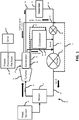
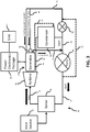
- Atomizer 82 atomizes the cooling liquid, which is then delivered to gap 70 in generator 26, where the relatively cool atomized liquid extracts heat from stator 72 and generator rotor 74 as it travels through the gap, including through the latent heat of vaporization with respect to portions of the atomized liquid that are vaporized by the heat in the stator and rotor.
- the atomized liquid is then extracted from generator 26 via fluid connection 34 along with the working fluid exhausted from turbine 24.
- atomizer 82 is depicted in dotted view to indicate that it is an optional element used in connection with one embodiment of the invention.
- the second volume of the atomized liquid (working fluid) introduced into gap 70 travels through the gap with a flow rate that is no more than 50% of the through flow rate of turbine 24.
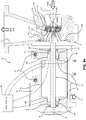
- generator 26 To permit high-speed (e.g., on the order of 20,000-25,000 rpm) operation, and to minimize maintenance, it may be desirable in some embodiments of generator 26 to support generator rotor 74 for rotational movement using magnetic radial bearings 88 (see FIG. 4 ).
- magnetic radial bearing 88a is positioned adjacent an end of generator rotor 74 proximate turbine 24 and magnet radial bearing 88b is positioned adjacent an opposite end of the rotor.
- this placement of bearings 88 enables in large part the overhung construction of turbine 24.
- axial movement of generator rotor 74 may be controlled through the use of magnetic axial thrust bearing 89.
- rolling element radial bearings 92 provide a rest point for generator rotor 74 when magnetic bearings 88 are not activated and provide a safe landing for the generator rotor in the event of a sudden electronic or power failure. It may be desirable in some cases to size rolling element radial bearings 92 to support generator rotor 74 with a relatively loose fit so that during operation when magnetic bearings 88 and 89 are energized, the rotor has limited, if any contact, with rolling element radial bearings 92, even during times of maximum radial deflections of generator rotor 74 due to perturbations in the operation of magnetic bearings 88. When fluid-film bearings are used in place of magnetic radial bearings 88, rolling element radial bearings 92 are typically not required, although in some applications it may be desirable to include such radial bearings.
- rolling element radial bearings 92 While beneficial for the reasons discussed above, rolling element radial bearings 92 also present a challenge because the radial clearance of such bearings is much higher than the desired clearances for the conventional seals (not shown in detail) of turbine 24.
- Typical rolling element radial bearings 92 have a radial clearance on the order of 0.005 to 0.015 inch.
- desired radial clearances for the seals of turbine 24 are typically on the order of 0.000 - 0.001 inch.
- each brush seal 94 is selected based upon the weight of generator rotor 74 and turbine rotor 104 (discussed below) coupled with the generator rotor, and the extent of radial movement of the rotors 74 and 104 that is permissible given the overall design and operating parameters, respectively, of generator 26 and turbine 24.
- such extent of radial deviation is 1.2 to 4 times greater than the extent of radial deviation of generator rotor 74 from co-axial alignment with rotational axis 106 that occurs when magnetic bearings 88 are fully activated and supporting generator rotor 74 for rotational movement through the course of normal operation.
- generator rotor 74 is free to move a first radial distance out of co-axial alignment with rotational axis 106 when magnetic bearings 88 are not activated and the generator rotor does not move radially more than a second radial distance out of co-axial alignment with rotation axis when supported by brush seals 94.
- the second radial distance is no more than 0.8 times the first radial distance, and in some implementations ranges from 0.2 to 0.6 times the first radial distance.
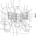
- turbine 24 is an overhung axial turbine and includes a housing 98 having an axial inlet 100 and a radial outlet 102.
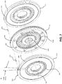
- Turbine 24, in one embodiment, is a multi-stage turbine, with the embodiment shown in FIG. 4a having three stages. In other embodiments discussed more below, turbine 24 may be a single-stage overhung radial turbine as show in FIG. 4b , and a multi-stage overhung radial turbine as shown in FIG. 4c .
- turbine 24 is constructed so that the working fluid is expanded as it is transported through the turbine, with the result that the cold end of the turbine, i.e., the end proximate radial outlet 102, is positioned adjacent generator 26. This arrangement reduces heat transfer from turbine 24 to generator 26.
- Turbine 24 includes a turbine rotor 104 that rotates about rotational axis 106 and a stator 108 that is fixed with respect to housing 98.
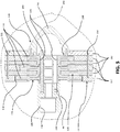
- turbine rotor 104 includes a plurality of individual bladed plates 110 and stator 108 includes a plurality of individual plates 112 positioned in alternating, inter-digitated relationship with the rotor plates, as best seen in FIGS. 5 , 6 and 9 .
- Rotor plates 110 and stator plates 112 are positioned within housing 98 in the cavity 114 formed at the region between inlet 100 and outlet 102. As best illustrated in FIGS.
- spacer segments 117 are formed as an integral portion of stator plates 112 (spacer segments are not separately labeled in FIGS. 9 and 10 ).
- each spacer segment 117 is sized with respect to its corresponding respective rotor plate 110 so that a gap 118 is provided between a radially outermost portion of the rotor plate and the radially innermost portion of the spacer segment.
- Seals 119 may be provided in gap 118 in certain embodiments of turbine 24.
- contact surfaces 130 and 132 of rotor plates 110, and contact surfaces 134 and 136 of stator plates 112 deviate from perfectly parallel by an amount in the range 0.0001" to 0.015", and in certain embodiments in the range 0.0005" to 0.005".
- Spacer segments 117 when provided, preferably have contact surfaces that are similarly flat and parallel to contact surfaces 130, 132, 134, and 136, as discussed above.
- a first rotor plate 110 e.g., plate 110a
- a second adjacent rotor plate e.g., plate 110b
- zero to one vane pitch i.e., (0) S to (1) S
- a first stator plate 112 e.g., plate 112a
- an adjacent stator plate e.g., plate 112c
- a blind bore 168 may be provided in a peripheral section 170 of a stator plate 112, e.g., stator plate 112a, immediately adjacent the stator plate, e.g., stator plate 112c, in which bores 160 are provided (rotor plate 110b and spacer plate 117 are intervening, of course).
- bores 160, 164 and 168 are spaced a substantially identical radial distance from rotational axis 106, and have a substantially identical diameter.
- the alignment system further includes pin 172, which is sized for receipt, typically using a mild friction fit, in a selected one of bores 160 and in bore 164.
- Stator plates 112, and spacer segments 117 are secured together in alternating, inter-digitated relationship so as to form a unitary cartridge 198.
- the latter may be releasably secured in cavity 114 ( FIG. 6 ) of housing 98 using known fasteners and other devices.
- cartridge 198 may be secured in cavity 114 by lock ring 200, which is engaged with a snap fit in a correspondingly sized recess 201 in in the cavity.
- stator plates 112 and spacers 117 may be secured together with pins 172 (see FIGS. 9 and 10 ), as discussed above, to ensure no relative rotational movement occurs.
- Pins 172 may also penetrate into floor 204 of housing 98 (such penetration not being shown) from the downstream-most spacer 117 or stator plate 112, if desired to assure no relative motion.
- a nose cone 206 may be provided, with one embodiment being threadedly engaged with threaded bore 208 in the furthest upstream stator plate 112 (identified in FIGS. 9 and 10 as S1).
- machine screws may be used to fasten nose cone 206 to first stator plate 112.
- Pins 210 may be used for precision rotational alignment of rotor plates 110, stator plates 112 and spacers 117, and if received in these components with a sufficient force fit, may also hold these components together to form a unitary structure, namely unitary cartridge 198.
- Bolt studs 212 in addition to providing some measure of rotational alignment, also draw together the rotor plates, stator plates and spacers to form a unitary structure, namely unitary cartridge 198.
- seal 220 surrounding stub shaft 189 of turbine 24 proximate the radially innermost portion of backplate 250.
- Seal 220 may be implemented as a labyrinth seal, a brush seal, a close-tolerance ring seal or using other seals known in the art.
- housing 98 is designed to facilitate such modification.
- One aspect of such design of housing 98 involves providing floor 204 with a thickness sufficient to accommodate turbine rotor 104 and stator 106 having varying radial heights. ⁇ r, as measured between said rotational axis and an outermost portion of said at least one turbine rotor, said axial turbine including a hood having a floor with a first thickness, wherein said first thickness is selected to permit said floor to be machined on the inside to a thickness sufficient to accommodate said at least one turbine rotor with a radial dimension that varies between ⁇ r and 1.4 ⁇ r.
- housing 98 is provided with a configuration that permits easy access to floor 204 by conventional machine tools, e.g., a 5-axis CNC milling machine or a CNC lathe, that can be used to machine the floor so as to create a cavity 114 sized to receive turbine rotor 104 and stator 106 with the desired radial heights.
- machine tools e.g., a 5-axis CNC milling machine or a CNC lathe, that can be used to machine the floor so as to create a cavity 114 sized to receive turbine rotor 104 and stator 106 with the desired radial heights.
- a modifiable housing 98 is to include a backplate 250 having a thickness that may be adjusted so as to selectively vary width l 4, i.e., the distance l 4 between backplate 250 and housing wall 252, and to selectively vary width l 1, i.e., the exit width.
- width l 4 may be varied so that it ranges from one half to four times the width of diffuser exit l 1.
- Backplate 250 may be an integral portion of housing 98 in some embodiments and a separate element in others, as illustrated in FIG. 4 .
- Backplate 250 preferably includes one or more ports 254 through which vapor in gap 70 may be exhausted and delivered to the exhaust flow path of turbine 24 and ultimately via fluid connection 34 to condenser 36.
- flow splitter 256 may be provided immediately downstream of turbine rotor 104 and stator 106 as another way to tailor the performance of turbine 24.
- an extension plate 258 may be added to nose 260 of floor 204 of housing 98, as best seen in FIG. 6 .
- l 1 If l 1 is increased for the diffuser, it will hurt the housing. This is controlled by starting with a generous housing design to cover a wide range of power levels (up to 5MW for certain designs) and then adjusting operating parameters by modifying backplate 250 and the nose 260 of floor 204. Another design variable is to introduce diffuser splitter 256 ( FIG. 6 ), which gives independent control on l 1, thereby permitting a selected change in the diffuser exit value. Further performance tailoring can be achieved by selection of an extension plate 258 ( FIG. 6 ) of suitable height and thickness.
- Turbine 24 is depicted in FIG. 4a as a multi-stage axial turbine 24, but turbine-generator system 20 is not so limited.
- turbine-generator system 20 may include a radial turbine 324 having a single stage.
- radial turbine 324 having a single stage.
- the latter includes a single rotor 104 and a single stator 108.
- turbine-generator system 20 may also be implemented using a mixed-flow turbine.
- the latter is very similar in design to radial turbine generators 324 and 424, and so is not separately illustrated.
- the turbine of the system described in paragraph 48 may be an axial turbine, a radial turbine or a mixed-flow turbine.
- the system described in paragraph 48 may include a hood having a removable backplate with a surface, a hood wall opposite the backplate, and a diffuser passage exit having a width l 1, wherein the backplate surface is spaced a distance l 4 from the hood wall, wherein the distance l4 ranges between one half and four times the distance l 1.
Landscapes
- Engineering & Computer Science (AREA)
- General Engineering & Computer Science (AREA)
- Mechanical Engineering (AREA)
- Power Engineering (AREA)
- Chemical & Material Sciences (AREA)
- Combustion & Propulsion (AREA)
- Ceramic Engineering (AREA)
- Connection Of Motors, Electrical Generators, Mechanical Devices, And The Like (AREA)
- Turbine Rotor Nozzle Sealing (AREA)
- Motor Or Generator Cooling System (AREA)
- Manufacture Of Motors, Generators (AREA)
Priority Applications (1)
| Application Number | Priority Date | Filing Date | Title |
|---|---|---|---|
| EP18213754.7A EP3536910B1 (en) | 2012-09-11 | 2013-09-11 | Overhung turbine with unitary cartridge |
Applications Claiming Priority (2)
| Application Number | Priority Date | Filing Date | Title |
|---|---|---|---|
| US201261699649P | 2012-09-11 | 2012-09-11 | |
| PCT/US2013/059275 WO2014043242A2 (en) | 2012-09-11 | 2013-09-11 | Overhung turbine and generator system with turbine cartridge |
Related Child Applications (1)
| Application Number | Title | Priority Date | Filing Date |
|---|---|---|---|
| EP18213754.7A Division EP3536910B1 (en) | 2012-09-11 | 2013-09-11 | Overhung turbine with unitary cartridge |
Publications (2)
| Publication Number | Publication Date |
|---|---|
| EP2917505A2 EP2917505A2 (en) | 2015-09-16 |
| EP2917505B1 true EP2917505B1 (en) | 2018-12-19 |
Family
ID=49304312
Family Applications (2)
| Application Number | Title | Priority Date | Filing Date |
|---|---|---|---|
| EP18213754.7A Active EP3536910B1 (en) | 2012-09-11 | 2013-09-11 | Overhung turbine with unitary cartridge |
| EP13773449.7A Active EP2917505B1 (en) | 2012-09-11 | 2013-09-11 | Overhung turbine and generator system with turbine cartridge |
Family Applications Before (1)
| Application Number | Title | Priority Date | Filing Date |
|---|---|---|---|
| EP18213754.7A Active EP3536910B1 (en) | 2012-09-11 | 2013-09-11 | Overhung turbine with unitary cartridge |
Country Status (5)
| Country | Link |
|---|---|
| US (5) | US9083212B2 (OSRAM) |
| EP (2) | EP3536910B1 (OSRAM) |
| JP (3) | JP2015533981A (OSRAM) |
| CN (2) | CN104838093B (OSRAM) |
| WO (1) | WO2014043242A2 (OSRAM) |
Families Citing this family (35)
| Publication number | Priority date | Publication date | Assignee | Title |
|---|---|---|---|---|
| JP2013169029A (ja) * | 2012-02-14 | 2013-08-29 | Kobe Steel Ltd | 発電装置 |
| US9083212B2 (en) | 2012-09-11 | 2015-07-14 | Concepts Eti, Inc. | Overhung turbine and generator system with turbine cartridge |
| EP2868874A1 (de) * | 2013-11-05 | 2015-05-06 | Siemens Aktiengesellschaft | Dampfkraftwerk mit einem flüssigkeitsgekühlten Generator |
| US9325224B2 (en) * | 2013-12-28 | 2016-04-26 | Google Inc. | Electrically-isolated and liquid-cooled rotor and stator assemblies |
| WO2016128527A1 (fr) * | 2015-02-11 | 2016-08-18 | Aqylon | Système thermodynamique |
| FR3032520A1 (fr) * | 2015-02-11 | 2016-08-12 | Aqylon | Systeme thermodynamique |
| FR3036154A1 (fr) * | 2015-05-13 | 2016-11-18 | Aqylon | Dispositif de transmission de couple pour une machine tournante, ensemble d'un tel dispositif et d'une turbine, d'un compresseur et/ou d'une pompe, et systeme comprenant un tel ensemble |
| US9963981B2 (en) * | 2015-06-10 | 2018-05-08 | General Electric Company | Pitch change mechanism for shrouded fan with low fan pressure ratio |
| KR101704306B1 (ko) * | 2015-12-29 | 2017-02-22 | 군산대학교산학협력단 | 레디얼 터빈을 이용한 폐열 회수 터빈 시스템 |
| CN107060909B (zh) * | 2016-12-17 | 2019-10-11 | 山东天瑞重工有限公司 | 一种带有新型推力轴承结构的透平机械 |
| JP6751031B2 (ja) | 2017-02-06 | 2020-09-02 | 株式会社神戸製鋼所 | 熱エネルギー回収装置 |
| DE102017208434A1 (de) * | 2017-05-18 | 2018-11-22 | Robert Bosch Gmbh | Abwärmerückgewinnungssystem |
| CN107476833B (zh) * | 2017-06-14 | 2019-05-14 | 南京航空航天大学 | 零泄漏自冷却的磁悬浮透平膨胀发电机及系统与方法 |
| CN107387172B (zh) * | 2017-08-17 | 2023-12-12 | 上海大学 | 立式双级永磁气悬浮orc余热发电机 |
| EP3460206A1 (de) | 2017-09-21 | 2019-03-27 | Siemens Aktiengesellschaft | Verfahren zum betreiben einer dampfturbine |
| JP6935766B2 (ja) * | 2018-02-15 | 2021-09-15 | 日本精工株式会社 | スピンドル装置 |
| US11441487B2 (en) * | 2018-04-27 | 2022-09-13 | Concepts Nrec, Llc | Turbomachine with internal bearing and rotor-spline interface cooling and systems incorporating the same |
| EP3578765B1 (de) * | 2018-06-08 | 2022-06-22 | Fludema GmbH | Betriebsverfahren für einen turbosatz und für eine niederdruckdampfturbinenanlage und niederdruckdampfturbinenanlage |
| WO2019241078A1 (en) | 2018-06-11 | 2019-12-19 | Smart E, Llc | Compact rankine turbogenerator device for distributed co-generation of heat and electricity |
| US11015846B2 (en) | 2018-12-20 | 2021-05-25 | AG Equipment Company | Heat of compression energy recovery system using a high speed generator converter system |
| CN109742898B (zh) * | 2018-12-28 | 2020-11-03 | 西安航天泵业有限公司 | 一种集成式全封闭低温液力发电装置 |
| WO2020181134A2 (en) * | 2019-03-06 | 2020-09-10 | Industrom Power, Llc | Compact axial turbine for high density working fluid |
| WO2020181137A1 (en) | 2019-03-06 | 2020-09-10 | Industrom Power, Llc | Intercooled cascade cycle waste heat recovery system |
| US11162379B2 (en) * | 2019-03-15 | 2021-11-02 | Hamilton Sundstrand Corporation | Temperature control device for tail cone mounted generator |
| CN110905609B (zh) * | 2019-05-28 | 2020-10-09 | 上海慕帆动力科技有限公司 | 应用于发动机余热回收的高参数orc透平发电设备及orc装置 |
| US11002146B1 (en) * | 2020-10-26 | 2021-05-11 | Antheon Research, Inc. | Power generation system |
| CN112372261B (zh) * | 2020-11-03 | 2022-05-17 | 重庆江增船舶重工有限公司 | 一种调节磁浮轴承、辅助轴承与转子装配间隙的方法 |
| US11591916B2 (en) * | 2021-07-02 | 2023-02-28 | Hamilton Sundstrand Corporation | Radial turbine rotor with complex cooling channels and method of making same |
| EP4148250B1 (en) | 2021-09-08 | 2025-08-06 | Rolls-Royce plc | An improved gas turbine engine |
| EP4148263A1 (en) * | 2021-09-08 | 2023-03-15 | Rolls-Royce plc | An improved gas turbine engine |
| CN113904499A (zh) * | 2021-10-18 | 2022-01-07 | 江苏讯智捷能源环保有限公司 | 一种新型磁悬浮余热涡轮发电机 |
| WO2023096980A1 (en) * | 2021-11-24 | 2023-06-01 | Enviro Power, Inc. | Turbo generator with separable shroud |
| WO2023113720A1 (en) * | 2021-12-16 | 2023-06-22 | Repg Enerji Sistemleri Sanayi Ve Ticaret Anonim Sirketi | An energy generation system |
| TWI781860B (zh) | 2021-12-28 | 2022-10-21 | 財團法人工業技術研究院 | 渦輪裝置及循環系統 |
| CN114542187B (zh) * | 2022-03-08 | 2024-03-08 | 重庆江增船舶重工有限公司 | 一种轴流外转子式磁浮orc有机工质膨胀发电机 |
Family Cites Families (41)
| Publication number | Priority date | Publication date | Assignee | Title |
|---|---|---|---|---|
| GB373010A (en) * | 1931-07-27 | 1932-05-19 | Asea Ab | Improvements in steam turbines |
| US3024366A (en) * | 1958-06-11 | 1962-03-06 | Yanagimachi Masanosuke | Electric generator system |
| FR1304689A (fr) * | 1961-08-04 | 1962-09-28 | Snecma | Pompe à vide turbomoléculaire perfectionnée |
| US4057371A (en) * | 1974-05-03 | 1977-11-08 | Norwalk-Turbo Inc. | Gas turbine driven high speed centrifugal compressor unit |
| SE395174B (sv) * | 1975-08-19 | 1977-08-01 | Stal Laval Turbin Ab | Forfarande for montering av turbomaskin samt verktyg for genomforande av forfarandet |
| US4098558A (en) * | 1976-08-23 | 1978-07-04 | Worthington Pump, Inc. | Preassembled unit or cartridge for multi-stage barrel type centrifugal pumps |
| US4363216A (en) * | 1980-10-23 | 1982-12-14 | Lucien Bronicki | Lubricating system for organic fluid power plant |
| JPS5795147A (en) * | 1980-12-01 | 1982-06-12 | Hitachi Ltd | Turbo-generator |
| US4362020A (en) * | 1981-02-11 | 1982-12-07 | Mechanical Technology Incorporated | Hermetic turbine generator |
| JPS5838301A (ja) * | 1981-08-29 | 1983-03-05 | Shimadzu Corp | 遠心式羽根車装置 |
| JPS59185802A (ja) * | 1983-04-05 | 1984-10-22 | Fuji Electric Co Ltd | 3流排気のタ−ビン |
| JPS62251402A (ja) * | 1986-04-25 | 1987-11-02 | Hitachi Ltd | 多段タ−ボ機械の積層ロ−タ |
| JPH01108301U (OSRAM) * | 1988-01-13 | 1989-07-21 | ||
| US5174120A (en) * | 1991-03-08 | 1992-12-29 | Westinghouse Electric Corp. | Turbine exhaust arrangement for improved efficiency |
| DE9215695U1 (de) | 1992-11-18 | 1993-10-14 | Anton Piller GmbH & Co KG, 37520 Osterode | Erdgas-Expansionsanlage |
| DE19518479A1 (de) | 1995-05-19 | 1996-11-21 | Thyssen Aufzuege Gmbh | Stromrichter |
| JP3323106B2 (ja) | 1996-10-16 | 2002-09-09 | 株式会社日立製作所 | 半導体電力変換装置 |
| DE19951954A1 (de) * | 1999-10-28 | 2001-05-03 | Pfeiffer Vacuum Gmbh | Turbomolekularpumpe |
| US6608418B2 (en) | 2001-08-24 | 2003-08-19 | Smiths Aerospace, Inc. | Permanent magnet turbo-generator having magnetic bearings |
| US7003956B2 (en) * | 2003-04-30 | 2006-02-28 | Kabushiki Kaisha Toshiba | Steam turbine, steam turbine plant and method of operating a steam turbine in a steam turbine plant |
| CN1573018B (zh) * | 2003-05-20 | 2010-09-15 | 株式会社东芝 | 蒸汽涡轮机 |
| BRPI0413986A (pt) | 2003-08-27 | 2006-11-07 | Ttl Dynamics Ltd | sistema de recuperação de energia, usos de hfe-7100 ou hexano ou água e de um dos alcanos, sistema de geração de energia elétrica, unidade de turbina de afluxo radial, mancal, acoplamento magnético rotativo, método realizado em um sistema de recuperação de energia para extrair energia a apartir de uma fonte de calor residual, método de controle de um sistema de recuperação de energia, e, sistemas de controle programável e de purificação de fluido de trabalho para um sistema de conversão de energia |
| JP4112468B2 (ja) * | 2003-10-02 | 2008-07-02 | 本田技研工業株式会社 | 回転軸 |
| US7146999B2 (en) | 2005-03-08 | 2006-12-12 | Gregory C. Giese | Modular fluid handling device |
| US7270512B2 (en) * | 2005-08-24 | 2007-09-18 | General Electric Company | Stacked steampath and grooved bucket wheels for steam turbines |
| US7640724B2 (en) | 2006-01-25 | 2010-01-05 | Siemens Energy, Inc. | System and method for improving the heat rate of a turbine |
| US20080001363A1 (en) * | 2006-06-28 | 2008-01-03 | General Electric Company | Brush sealing system and method for rotary machines |
| US7638892B2 (en) * | 2007-04-16 | 2009-12-29 | Calnetix, Inc. | Generating energy from fluid expansion |
| US7841306B2 (en) | 2007-04-16 | 2010-11-30 | Calnetix Power Solutions, Inc. | Recovering heat energy |
| US7726331B1 (en) | 2007-05-23 | 2010-06-01 | Giese Gregory C | Modular fluid handling device II |
| DE102007032933B4 (de) * | 2007-07-14 | 2015-02-19 | Atlas Copco Energas Gmbh | Turbomaschine |
| US8092158B2 (en) * | 2007-08-16 | 2012-01-10 | Johnson Controls Technology Company | Method of positioning seals in turbomachinery utilizing electromagnetic bearings |
| JP4929188B2 (ja) * | 2008-01-08 | 2012-05-09 | 株式会社東芝 | 地熱発電システム、地熱発電装置ならびに地熱発電方法 |
| US8028996B2 (en) * | 2008-04-04 | 2011-10-04 | General Electric Company | System and method for adjusting stiffness of a brush sealing system |
| US20090277400A1 (en) * | 2008-05-06 | 2009-11-12 | Ronald David Conry | Rankine cycle heat recovery methods and devices |
| EP2148103B1 (de) * | 2008-07-21 | 2011-01-26 | Siemens Aktiengesellschaft | Magnetisches Radiallager mit Permanentmagneten zur Vormagnetisierung sowie magnetisches Lagersystem mit einem derartigen magnetischen Radiallager |
| US20100327534A1 (en) * | 2009-06-26 | 2010-12-30 | General Electric Company | Magnetic brush seal system |
| US8739538B2 (en) | 2010-05-28 | 2014-06-03 | General Electric Company | Generating energy from fluid expansion |
| US8684684B2 (en) * | 2010-08-31 | 2014-04-01 | General Electric Company | Turbine assembly with end-wall-contoured airfoils and preferenttial clocking |
| US9476428B2 (en) | 2011-06-01 | 2016-10-25 | R & D Dynamics Corporation | Ultra high pressure turbomachine for waste heat recovery |
| US9083212B2 (en) | 2012-09-11 | 2015-07-14 | Concepts Eti, Inc. | Overhung turbine and generator system with turbine cartridge |
-
2013
- 2013-07-09 US US13/937,978 patent/US9083212B2/en active Active
- 2013-09-11 JP JP2015531336A patent/JP2015533981A/ja active Pending
- 2013-09-11 WO PCT/US2013/059275 patent/WO2014043242A2/en not_active Ceased
- 2013-09-11 CN CN201380057879.7A patent/CN104838093B/zh active Active
- 2013-09-11 EP EP18213754.7A patent/EP3536910B1/en active Active
- 2013-09-11 CN CN201710253050.4A patent/CN106988796B/zh active Active
- 2013-09-11 EP EP13773449.7A patent/EP2917505B1/en active Active
-
2015
- 2015-07-13 US US14/797,639 patent/US20150322811A1/en not_active Abandoned
-
2016
- 2016-08-03 US US15/227,604 patent/US10069378B2/en active Active
-
2018
- 2018-09-03 US US16/120,351 patent/US10715008B2/en active Active
-
2019
- 2019-04-18 JP JP2019079196A patent/JP6856695B2/ja active Active
-
2020
- 2020-06-08 US US16/946,138 patent/US11522413B2/en active Active
-
2021
- 2021-03-18 JP JP2021044737A patent/JP7160984B2/ja active Active
Non-Patent Citations (1)
| Title |
|---|
| None * |
Also Published As
| Publication number | Publication date |
|---|---|
| US9083212B2 (en) | 2015-07-14 |
| EP3536910B1 (en) | 2021-06-16 |
| US20200303993A1 (en) | 2020-09-24 |
| US20190068027A1 (en) | 2019-02-28 |
| WO2014043242A2 (en) | 2014-03-20 |
| CN104838093B (zh) | 2017-05-10 |
| JP2015533981A (ja) | 2015-11-26 |
| US20160344258A1 (en) | 2016-11-24 |
| CN106988796B (zh) | 2019-05-17 |
| JP7160984B2 (ja) | 2022-10-25 |
| US11522413B2 (en) | 2022-12-06 |
| JP2019173755A (ja) | 2019-10-10 |
| JP6856695B2 (ja) | 2021-04-07 |
| EP3536910A1 (en) | 2019-09-11 |
| US10069378B2 (en) | 2018-09-04 |
| EP2917505A2 (en) | 2015-09-16 |
| JP2021095914A (ja) | 2021-06-24 |
| US20150322811A1 (en) | 2015-11-12 |
| US10715008B2 (en) | 2020-07-14 |
| US20150037136A1 (en) | 2015-02-05 |
| CN104838093A (zh) | 2015-08-12 |
| WO2014043242A3 (en) | 2014-07-24 |
| CN106988796A (zh) | 2017-07-28 |
Similar Documents
| Publication | Publication Date | Title |
|---|---|---|
| US11522413B2 (en) | ORC turbine and generator, and method of making a turbine | |
| RU2578075C2 (ru) | Устройство и способ выработки энергии посредством органического цикла ренкина | |
| EP3123018A1 (en) | Gas turbine generator with a pre-combustion power turbine | |
| US20180058242A1 (en) | Multi-spool gas turbine arrangement | |
| KR20190032846A (ko) | 터빈지지구조, 이를 이용한 터빈 및 가스터빈 | |
| HK1249158A1 (en) | Multi-spool gas turbine arrangement | |
| EP3274563B1 (en) | Two-spool gas turbine arrangement | |
| KR102113100B1 (ko) | 오버행 터빈 및 자기 베어링을 가진 발전기 시스템 | |
| JP6929942B2 (ja) | 低蒸気温度で作動するように適合される多段軸流タービン | |
| Kraus et al. | Hermetic 40-kW-Class Steam Turbine System for the Bottoming Cycle of Internal Combustion Engines | |
| JP2017526844A (ja) | 作動流体を膨張させるためのタービンおよび方法 | |
| KR101206287B1 (ko) | 마이크로 가스 터빈의 냉각장치 및 이를 구비한 마이크로 가스 터빈 | |
| KR20130092277A (ko) | 회전체 및 이를 구비한 가스 터빈 | |
| WO2024083762A1 (en) | Pressure compounded radial flow re-entry turbine | |
| JP2004346805A (ja) | タービンロータ及びタービンステータの製作方法 | |
| KR20200037671A (ko) | 터빈장치 | |
| HK1249159B (en) | Two-spool gas turbine arrangement |
Legal Events
| Date | Code | Title | Description |
|---|---|---|---|
| PUAI | Public reference made under article 153(3) epc to a published international application that has entered the european phase |
Free format text: ORIGINAL CODE: 0009012 |
|
| 17P | Request for examination filed |
Effective date: 20150410 |
|
| AK | Designated contracting states |
Kind code of ref document: A2 Designated state(s): AL AT BE BG CH CY CZ DE DK EE ES FI FR GB GR HR HU IE IS IT LI LT LU LV MC MK MT NL NO PL PT RO RS SE SI SK SM TR |
|
| AX | Request for extension of the european patent |
Extension state: BA ME |
|
| DAX | Request for extension of the european patent (deleted) | ||
| 17Q | First examination report despatched |
Effective date: 20160602 |
|
| RAP1 | Party data changed (applicant data changed or rights of an application transferred) |
Owner name: CONCEPTS NREC, LLC |
|
| STAA | Information on the status of an ep patent application or granted ep patent |
Free format text: STATUS: EXAMINATION IS IN PROGRESS |
|
| R17C | First examination report despatched (corrected) |
Effective date: 20160602 |
|
| GRAP | Despatch of communication of intention to grant a patent |
Free format text: ORIGINAL CODE: EPIDOSNIGR1 |
|
| STAA | Information on the status of an ep patent application or granted ep patent |
Free format text: STATUS: GRANT OF PATENT IS INTENDED |
|
| INTG | Intention to grant announced |
Effective date: 20180420 |
|
| GRAJ | Information related to disapproval of communication of intention to grant by the applicant or resumption of examination proceedings by the epo deleted |
Free format text: ORIGINAL CODE: EPIDOSDIGR1 |
|
| STAA | Information on the status of an ep patent application or granted ep patent |
Free format text: STATUS: EXAMINATION IS IN PROGRESS |
|
| INTC | Intention to grant announced (deleted) | ||
| GRAR | Information related to intention to grant a patent recorded |
Free format text: ORIGINAL CODE: EPIDOSNIGR71 |
|
| GRAS | Grant fee paid |
Free format text: ORIGINAL CODE: EPIDOSNIGR3 |
|
| STAA | Information on the status of an ep patent application or granted ep patent |
Free format text: STATUS: GRANT OF PATENT IS INTENDED |
|
| GRAA | (expected) grant |
Free format text: ORIGINAL CODE: 0009210 |
|
| STAA | Information on the status of an ep patent application or granted ep patent |
Free format text: STATUS: THE PATENT HAS BEEN GRANTED |
|
| AK | Designated contracting states |
Kind code of ref document: B1 Designated state(s): AL AT BE BG CH CY CZ DE DK EE ES FI FR GB GR HR HU IE IS IT LI LT LU LV MC MK MT NL NO PL PT RO RS SE SI SK SM TR |
|
| INTG | Intention to grant announced |
Effective date: 20181112 |
|
| REG | Reference to a national code |
Ref country code: GB Ref legal event code: FG4D |
|
| REG | Reference to a national code |
Ref country code: CH Ref legal event code: EP |
|
| REG | Reference to a national code |
Ref country code: IE Ref legal event code: FG4D |
|
| REG | Reference to a national code |
Ref country code: DE Ref legal event code: R096 Ref document number: 602013048477 Country of ref document: DE |
|
| REG | Reference to a national code |
Ref country code: AT Ref legal event code: REF Ref document number: 1078947 Country of ref document: AT Kind code of ref document: T Effective date: 20190115 |
|
| REG | Reference to a national code |
Ref country code: NL Ref legal event code: MP Effective date: 20181219 |
|
| PG25 | Lapsed in a contracting state [announced via postgrant information from national office to epo] |
Ref country code: LV Free format text: LAPSE BECAUSE OF FAILURE TO SUBMIT A TRANSLATION OF THE DESCRIPTION OR TO PAY THE FEE WITHIN THE PRESCRIBED TIME-LIMIT Effective date: 20181219 Ref country code: HR Free format text: LAPSE BECAUSE OF FAILURE TO SUBMIT A TRANSLATION OF THE DESCRIPTION OR TO PAY THE FEE WITHIN THE PRESCRIBED TIME-LIMIT Effective date: 20181219 Ref country code: NO Free format text: LAPSE BECAUSE OF FAILURE TO SUBMIT A TRANSLATION OF THE DESCRIPTION OR TO PAY THE FEE WITHIN THE PRESCRIBED TIME-LIMIT Effective date: 20190319 Ref country code: BG Free format text: LAPSE BECAUSE OF FAILURE TO SUBMIT A TRANSLATION OF THE DESCRIPTION OR TO PAY THE FEE WITHIN THE PRESCRIBED TIME-LIMIT Effective date: 20190319 Ref country code: LT Free format text: LAPSE BECAUSE OF FAILURE TO SUBMIT A TRANSLATION OF THE DESCRIPTION OR TO PAY THE FEE WITHIN THE PRESCRIBED TIME-LIMIT Effective date: 20181219 Ref country code: FI Free format text: LAPSE BECAUSE OF FAILURE TO SUBMIT A TRANSLATION OF THE DESCRIPTION OR TO PAY THE FEE WITHIN THE PRESCRIBED TIME-LIMIT Effective date: 20181219 |
|
| REG | Reference to a national code |
Ref country code: LT Ref legal event code: MG4D |
|
| REG | Reference to a national code |
Ref country code: AT Ref legal event code: MK05 Ref document number: 1078947 Country of ref document: AT Kind code of ref document: T Effective date: 20181219 |
|
| PG25 | Lapsed in a contracting state [announced via postgrant information from national office to epo] |
Ref country code: AL Free format text: LAPSE BECAUSE OF FAILURE TO SUBMIT A TRANSLATION OF THE DESCRIPTION OR TO PAY THE FEE WITHIN THE PRESCRIBED TIME-LIMIT Effective date: 20181219 Ref country code: SE Free format text: LAPSE BECAUSE OF FAILURE TO SUBMIT A TRANSLATION OF THE DESCRIPTION OR TO PAY THE FEE WITHIN THE PRESCRIBED TIME-LIMIT Effective date: 20181219 Ref country code: RS Free format text: LAPSE BECAUSE OF FAILURE TO SUBMIT A TRANSLATION OF THE DESCRIPTION OR TO PAY THE FEE WITHIN THE PRESCRIBED TIME-LIMIT Effective date: 20181219 Ref country code: GR Free format text: LAPSE BECAUSE OF FAILURE TO SUBMIT A TRANSLATION OF THE DESCRIPTION OR TO PAY THE FEE WITHIN THE PRESCRIBED TIME-LIMIT Effective date: 20190320 |
|
| PG25 | Lapsed in a contracting state [announced via postgrant information from national office to epo] |
Ref country code: NL Free format text: LAPSE BECAUSE OF FAILURE TO SUBMIT A TRANSLATION OF THE DESCRIPTION OR TO PAY THE FEE WITHIN THE PRESCRIBED TIME-LIMIT Effective date: 20181219 |
|
| PG25 | Lapsed in a contracting state [announced via postgrant information from national office to epo] |
Ref country code: PT Free format text: LAPSE BECAUSE OF FAILURE TO SUBMIT A TRANSLATION OF THE DESCRIPTION OR TO PAY THE FEE WITHIN THE PRESCRIBED TIME-LIMIT Effective date: 20190419 Ref country code: CZ Free format text: LAPSE BECAUSE OF FAILURE TO SUBMIT A TRANSLATION OF THE DESCRIPTION OR TO PAY THE FEE WITHIN THE PRESCRIBED TIME-LIMIT Effective date: 20181219 Ref country code: ES Free format text: LAPSE BECAUSE OF FAILURE TO SUBMIT A TRANSLATION OF THE DESCRIPTION OR TO PAY THE FEE WITHIN THE PRESCRIBED TIME-LIMIT Effective date: 20181219 Ref country code: IT Free format text: LAPSE BECAUSE OF FAILURE TO SUBMIT A TRANSLATION OF THE DESCRIPTION OR TO PAY THE FEE WITHIN THE PRESCRIBED TIME-LIMIT Effective date: 20181219 Ref country code: PL Free format text: LAPSE BECAUSE OF FAILURE TO SUBMIT A TRANSLATION OF THE DESCRIPTION OR TO PAY THE FEE WITHIN THE PRESCRIBED TIME-LIMIT Effective date: 20181219 |
|
| PG25 | Lapsed in a contracting state [announced via postgrant information from national office to epo] |
Ref country code: EE Free format text: LAPSE BECAUSE OF FAILURE TO SUBMIT A TRANSLATION OF THE DESCRIPTION OR TO PAY THE FEE WITHIN THE PRESCRIBED TIME-LIMIT Effective date: 20181219 Ref country code: SM Free format text: LAPSE BECAUSE OF FAILURE TO SUBMIT A TRANSLATION OF THE DESCRIPTION OR TO PAY THE FEE WITHIN THE PRESCRIBED TIME-LIMIT Effective date: 20181219 Ref country code: SK Free format text: LAPSE BECAUSE OF FAILURE TO SUBMIT A TRANSLATION OF THE DESCRIPTION OR TO PAY THE FEE WITHIN THE PRESCRIBED TIME-LIMIT Effective date: 20181219 Ref country code: RO Free format text: LAPSE BECAUSE OF FAILURE TO SUBMIT A TRANSLATION OF THE DESCRIPTION OR TO PAY THE FEE WITHIN THE PRESCRIBED TIME-LIMIT Effective date: 20181219 Ref country code: IS Free format text: LAPSE BECAUSE OF FAILURE TO SUBMIT A TRANSLATION OF THE DESCRIPTION OR TO PAY THE FEE WITHIN THE PRESCRIBED TIME-LIMIT Effective date: 20190419 |
|
| REG | Reference to a national code |
Ref country code: DE Ref legal event code: R097 Ref document number: 602013048477 Country of ref document: DE |
|
| PLBE | No opposition filed within time limit |
Free format text: ORIGINAL CODE: 0009261 |
|
| STAA | Information on the status of an ep patent application or granted ep patent |
Free format text: STATUS: NO OPPOSITION FILED WITHIN TIME LIMIT |
|
| PG25 | Lapsed in a contracting state [announced via postgrant information from national office to epo] |
Ref country code: AT Free format text: LAPSE BECAUSE OF FAILURE TO SUBMIT A TRANSLATION OF THE DESCRIPTION OR TO PAY THE FEE WITHIN THE PRESCRIBED TIME-LIMIT Effective date: 20181219 Ref country code: DK Free format text: LAPSE BECAUSE OF FAILURE TO SUBMIT A TRANSLATION OF THE DESCRIPTION OR TO PAY THE FEE WITHIN THE PRESCRIBED TIME-LIMIT Effective date: 20181219 |
|
| 26N | No opposition filed |
Effective date: 20190920 |
|
| PG25 | Lapsed in a contracting state [announced via postgrant information from national office to epo] |
Ref country code: SI Free format text: LAPSE BECAUSE OF FAILURE TO SUBMIT A TRANSLATION OF THE DESCRIPTION OR TO PAY THE FEE WITHIN THE PRESCRIBED TIME-LIMIT Effective date: 20181219 |
|
| PG25 | Lapsed in a contracting state [announced via postgrant information from national office to epo] |
Ref country code: TR Free format text: LAPSE BECAUSE OF FAILURE TO SUBMIT A TRANSLATION OF THE DESCRIPTION OR TO PAY THE FEE WITHIN THE PRESCRIBED TIME-LIMIT Effective date: 20181219 |
|
| PG25 | Lapsed in a contracting state [announced via postgrant information from national office to epo] |
Ref country code: MC Free format text: LAPSE BECAUSE OF FAILURE TO SUBMIT A TRANSLATION OF THE DESCRIPTION OR TO PAY THE FEE WITHIN THE PRESCRIBED TIME-LIMIT Effective date: 20181219 |
|
| REG | Reference to a national code |
Ref country code: CH Ref legal event code: PL |
|
| PG25 | Lapsed in a contracting state [announced via postgrant information from national office to epo] |
Ref country code: CH Free format text: LAPSE BECAUSE OF NON-PAYMENT OF DUE FEES Effective date: 20190930 Ref country code: LU Free format text: LAPSE BECAUSE OF NON-PAYMENT OF DUE FEES Effective date: 20190911 Ref country code: IE Free format text: LAPSE BECAUSE OF NON-PAYMENT OF DUE FEES Effective date: 20190911 Ref country code: LI Free format text: LAPSE BECAUSE OF NON-PAYMENT OF DUE FEES Effective date: 20190930 |
|
| REG | Reference to a national code |
Ref country code: BE Ref legal event code: MM Effective date: 20190930 |
|
| PG25 | Lapsed in a contracting state [announced via postgrant information from national office to epo] |
Ref country code: BE Free format text: LAPSE BECAUSE OF NON-PAYMENT OF DUE FEES Effective date: 20190930 |
|
| PG25 | Lapsed in a contracting state [announced via postgrant information from national office to epo] |
Ref country code: CY Free format text: LAPSE BECAUSE OF FAILURE TO SUBMIT A TRANSLATION OF THE DESCRIPTION OR TO PAY THE FEE WITHIN THE PRESCRIBED TIME-LIMIT Effective date: 20181219 |
|
| PG25 | Lapsed in a contracting state [announced via postgrant information from national office to epo] |
Ref country code: MT Free format text: LAPSE BECAUSE OF FAILURE TO SUBMIT A TRANSLATION OF THE DESCRIPTION OR TO PAY THE FEE WITHIN THE PRESCRIBED TIME-LIMIT Effective date: 20181219 Ref country code: HU Free format text: LAPSE BECAUSE OF FAILURE TO SUBMIT A TRANSLATION OF THE DESCRIPTION OR TO PAY THE FEE WITHIN THE PRESCRIBED TIME-LIMIT; INVALID AB INITIO Effective date: 20130911 |
|
| PGFP | Annual fee paid to national office [announced via postgrant information from national office to epo] |
Ref country code: FR Payment date: 20210927 Year of fee payment: 9 |
|
| PGFP | Annual fee paid to national office [announced via postgrant information from national office to epo] |
Ref country code: GB Payment date: 20210927 Year of fee payment: 9 |
|
| PG25 | Lapsed in a contracting state [announced via postgrant information from national office to epo] |
Ref country code: MK Free format text: LAPSE BECAUSE OF FAILURE TO SUBMIT A TRANSLATION OF THE DESCRIPTION OR TO PAY THE FEE WITHIN THE PRESCRIBED TIME-LIMIT Effective date: 20181219 |
|
| GBPC | Gb: european patent ceased through non-payment of renewal fee |
Effective date: 20220911 |
|
| P01 | Opt-out of the competence of the unified patent court (upc) registered |
Effective date: 20230525 |
|
| PG25 | Lapsed in a contracting state [announced via postgrant information from national office to epo] |
Ref country code: FR Free format text: LAPSE BECAUSE OF NON-PAYMENT OF DUE FEES Effective date: 20220930 |
|
| PG25 | Lapsed in a contracting state [announced via postgrant information from national office to epo] |
Ref country code: GB Free format text: LAPSE BECAUSE OF NON-PAYMENT OF DUE FEES Effective date: 20220911 |
|
| PGFP | Annual fee paid to national office [announced via postgrant information from national office to epo] |
Ref country code: DE Payment date: 20250929 Year of fee payment: 13 |