EP3536910B1 - Overhung turbine with unitary cartridge - Google Patents
Overhung turbine with unitary cartridge Download PDFInfo
- Publication number
- EP3536910B1 EP3536910B1 EP18213754.7A EP18213754A EP3536910B1 EP 3536910 B1 EP3536910 B1 EP 3536910B1 EP 18213754 A EP18213754 A EP 18213754A EP 3536910 B1 EP3536910 B1 EP 3536910B1
- Authority
- EP
- European Patent Office
- Prior art keywords
- turbine
- stator
- rotor
- plates
- generator
- Prior art date
- Legal status (The legal status is an assumption and is not a legal conclusion. Google has not performed a legal analysis and makes no representation as to the accuracy of the status listed.)
- Active
Links
- 125000006850 spacer group Chemical group 0.000 claims description 27
- 230000002093 peripheral effect Effects 0.000 claims description 5
- 239000012530 fluid Substances 0.000 description 44
- 239000007788 liquid Substances 0.000 description 15
- 238000005096 rolling process Methods 0.000 description 14
- 238000001816 cooling Methods 0.000 description 12
- 238000013461 design Methods 0.000 description 12
- 239000010408 film Substances 0.000 description 7
- 239000000110 cooling liquid Substances 0.000 description 6
- 239000007789 gas Substances 0.000 description 6
- 238000006243 chemical reaction Methods 0.000 description 5
- 238000012546 transfer Methods 0.000 description 5
- 238000011144 upstream manufacturing Methods 0.000 description 5
- 238000010276 construction Methods 0.000 description 4
- 230000005611 electricity Effects 0.000 description 4
- 238000012423 maintenance Methods 0.000 description 4
- 239000006200 vaporizer Substances 0.000 description 4
- 239000002918 waste heat Substances 0.000 description 4
- 239000000284 extract Substances 0.000 description 3
- 238000004519 manufacturing process Methods 0.000 description 3
- 238000000034 method Methods 0.000 description 3
- 238000011084 recovery Methods 0.000 description 3
- QGZKDVFQNNGYKY-UHFFFAOYSA-N Ammonia Chemical compound N QGZKDVFQNNGYKY-UHFFFAOYSA-N 0.000 description 2
- 239000002440 industrial waste Substances 0.000 description 2
- 229910021529 ammonia Inorganic materials 0.000 description 1
- 238000004458 analytical method Methods 0.000 description 1
- 238000013459 approach Methods 0.000 description 1
- 230000009286 beneficial effect Effects 0.000 description 1
- 238000002474 experimental method Methods 0.000 description 1
- -1 i.e. Substances 0.000 description 1
- 230000006698 induction Effects 0.000 description 1
- 238000005339 levitation Methods 0.000 description 1
- 238000003801 milling Methods 0.000 description 1
- 238000012986 modification Methods 0.000 description 1
- 230000004048 modification Effects 0.000 description 1
- 230000035515 penetration Effects 0.000 description 1
- MSSNHSVIGIHOJA-UHFFFAOYSA-N pentafluoropropane Chemical compound FC(F)CC(F)(F)F MSSNHSVIGIHOJA-UHFFFAOYSA-N 0.000 description 1
- 239000003507 refrigerant Substances 0.000 description 1
- 230000000630 rising effect Effects 0.000 description 1
- 238000004513 sizing Methods 0.000 description 1
- 230000001360 synchronised effect Effects 0.000 description 1
- 239000010409 thin film Substances 0.000 description 1
- 238000009834 vaporization Methods 0.000 description 1
- 230000008016 vaporization Effects 0.000 description 1
- XLYOFNOQVPJJNP-UHFFFAOYSA-N water Substances O XLYOFNOQVPJJNP-UHFFFAOYSA-N 0.000 description 1
Images


Classifications
-
- B—PERFORMING OPERATIONS; TRANSPORTING
- B23—MACHINE TOOLS; METAL-WORKING NOT OTHERWISE PROVIDED FOR
- B23P—METAL-WORKING NOT OTHERWISE PROVIDED FOR; COMBINED OPERATIONS; UNIVERSAL MACHINE TOOLS
- B23P15/00—Making specific metal objects by operations not covered by a single other subclass or a group in this subclass
-
- F—MECHANICAL ENGINEERING; LIGHTING; HEATING; WEAPONS; BLASTING
- F01—MACHINES OR ENGINES IN GENERAL; ENGINE PLANTS IN GENERAL; STEAM ENGINES
- F01D—NON-POSITIVE DISPLACEMENT MACHINES OR ENGINES, e.g. STEAM TURBINES
- F01D15/00—Adaptations of machines or engines for special use; Combinations of engines with devices driven thereby
- F01D15/10—Adaptations for driving, or combinations with, electric generators
-
- F—MECHANICAL ENGINEERING; LIGHTING; HEATING; WEAPONS; BLASTING
- F01—MACHINES OR ENGINES IN GENERAL; ENGINE PLANTS IN GENERAL; STEAM ENGINES
- F01D—NON-POSITIVE DISPLACEMENT MACHINES OR ENGINES, e.g. STEAM TURBINES
- F01D25/00—Component parts, details, or accessories, not provided for in, or of interest apart from, other groups
- F01D25/16—Arrangement of bearings; Supporting or mounting bearings in casings
-
- F—MECHANICAL ENGINEERING; LIGHTING; HEATING; WEAPONS; BLASTING
- F01—MACHINES OR ENGINES IN GENERAL; ENGINE PLANTS IN GENERAL; STEAM ENGINES
- F01D—NON-POSITIVE DISPLACEMENT MACHINES OR ENGINES, e.g. STEAM TURBINES
- F01D25/00—Component parts, details, or accessories, not provided for in, or of interest apart from, other groups
- F01D25/24—Casings; Casing parts, e.g. diaphragms, casing fastenings
- F01D25/243—Flange connections; Bolting arrangements
-
- F—MECHANICAL ENGINEERING; LIGHTING; HEATING; WEAPONS; BLASTING
- F01—MACHINES OR ENGINES IN GENERAL; ENGINE PLANTS IN GENERAL; STEAM ENGINES
- F01D—NON-POSITIVE DISPLACEMENT MACHINES OR ENGINES, e.g. STEAM TURBINES
- F01D5/00—Blades; Blade-carrying members; Heating, heat-insulating, cooling or antivibration means on the blades or the members
- F01D5/02—Blade-carrying members, e.g. rotors
- F01D5/025—Fixing blade carrying members on shafts
-
- F—MECHANICAL ENGINEERING; LIGHTING; HEATING; WEAPONS; BLASTING
- F01—MACHINES OR ENGINES IN GENERAL; ENGINE PLANTS IN GENERAL; STEAM ENGINES
- F01D—NON-POSITIVE DISPLACEMENT MACHINES OR ENGINES, e.g. STEAM TURBINES
- F01D5/00—Blades; Blade-carrying members; Heating, heat-insulating, cooling or antivibration means on the blades or the members
- F01D5/02—Blade-carrying members, e.g. rotors
- F01D5/06—Rotors for more than one axial stage, e.g. of drum or multiple disc type; Details thereof, e.g. shafts, shaft connections
- F01D5/066—Connecting means for joining rotor-discs or rotor-elements together, e.g. by a central bolt, by clamps
-
- F—MECHANICAL ENGINEERING; LIGHTING; HEATING; WEAPONS; BLASTING
- F01—MACHINES OR ENGINES IN GENERAL; ENGINE PLANTS IN GENERAL; STEAM ENGINES
- F01D—NON-POSITIVE DISPLACEMENT MACHINES OR ENGINES, e.g. STEAM TURBINES
- F01D5/00—Blades; Blade-carrying members; Heating, heat-insulating, cooling or antivibration means on the blades or the members
- F01D5/12—Blades
- F01D5/22—Blade-to-blade connections, e.g. for damping vibrations
- F01D5/225—Blade-to-blade connections, e.g. for damping vibrations by shrouding
-
- F—MECHANICAL ENGINEERING; LIGHTING; HEATING; WEAPONS; BLASTING
- F01—MACHINES OR ENGINES IN GENERAL; ENGINE PLANTS IN GENERAL; STEAM ENGINES
- F01D—NON-POSITIVE DISPLACEMENT MACHINES OR ENGINES, e.g. STEAM TURBINES
- F01D5/00—Blades; Blade-carrying members; Heating, heat-insulating, cooling or antivibration means on the blades or the members
- F01D5/34—Rotor-blade aggregates of unitary construction, e.g. formed of sheet laminae
-
- F—MECHANICAL ENGINEERING; LIGHTING; HEATING; WEAPONS; BLASTING
- F01—MACHINES OR ENGINES IN GENERAL; ENGINE PLANTS IN GENERAL; STEAM ENGINES
- F01D—NON-POSITIVE DISPLACEMENT MACHINES OR ENGINES, e.g. STEAM TURBINES
- F01D9/00—Stators
- F01D9/02—Nozzles; Nozzle boxes; Stator blades; Guide conduits, e.g. individual nozzles
- F01D9/04—Nozzles; Nozzle boxes; Stator blades; Guide conduits, e.g. individual nozzles forming ring or sector
- F01D9/042—Nozzles; Nozzle boxes; Stator blades; Guide conduits, e.g. individual nozzles forming ring or sector fixing blades to stators
- F01D9/044—Nozzles; Nozzle boxes; Stator blades; Guide conduits, e.g. individual nozzles forming ring or sector fixing blades to stators permanently, e.g. by welding, brazing, casting or the like
-
- F—MECHANICAL ENGINEERING; LIGHTING; HEATING; WEAPONS; BLASTING
- F01—MACHINES OR ENGINES IN GENERAL; ENGINE PLANTS IN GENERAL; STEAM ENGINES
- F01K—STEAM ENGINE PLANTS; STEAM ACCUMULATORS; ENGINE PLANTS NOT OTHERWISE PROVIDED FOR; ENGINES USING SPECIAL WORKING FLUIDS OR CYCLES
- F01K25/00—Plants or engines characterised by use of special working fluids, not otherwise provided for; Plants operating in closed cycles and not otherwise provided for
- F01K25/08—Plants or engines characterised by use of special working fluids, not otherwise provided for; Plants operating in closed cycles and not otherwise provided for using special vapours
-
- F—MECHANICAL ENGINEERING; LIGHTING; HEATING; WEAPONS; BLASTING
- F01—MACHINES OR ENGINES IN GENERAL; ENGINE PLANTS IN GENERAL; STEAM ENGINES
- F01K—STEAM ENGINE PLANTS; STEAM ACCUMULATORS; ENGINE PLANTS NOT OTHERWISE PROVIDED FOR; ENGINES USING SPECIAL WORKING FLUIDS OR CYCLES
- F01K27/00—Plants for converting heat or fluid energy into mechanical energy, not otherwise provided for
- F01K27/02—Plants modified to use their waste heat, other than that of exhaust, e.g. engine-friction heat
-
- F—MECHANICAL ENGINEERING; LIGHTING; HEATING; WEAPONS; BLASTING
- F16—ENGINEERING ELEMENTS AND UNITS; GENERAL MEASURES FOR PRODUCING AND MAINTAINING EFFECTIVE FUNCTIONING OF MACHINES OR INSTALLATIONS; THERMAL INSULATION IN GENERAL
- F16C—SHAFTS; FLEXIBLE SHAFTS; ELEMENTS OR CRANKSHAFT MECHANISMS; ROTARY BODIES OTHER THAN GEARING ELEMENTS; BEARINGS
- F16C32/00—Bearings not otherwise provided for
- F16C32/04—Bearings not otherwise provided for using magnetic or electric supporting means
- F16C32/0402—Bearings not otherwise provided for using magnetic or electric supporting means combined with other supporting means, e.g. hybrid bearings with both magnetic and fluid supporting means
-
- F—MECHANICAL ENGINEERING; LIGHTING; HEATING; WEAPONS; BLASTING
- F16—ENGINEERING ELEMENTS AND UNITS; GENERAL MEASURES FOR PRODUCING AND MAINTAINING EFFECTIVE FUNCTIONING OF MACHINES OR INSTALLATIONS; THERMAL INSULATION IN GENERAL
- F16C—SHAFTS; FLEXIBLE SHAFTS; ELEMENTS OR CRANKSHAFT MECHANISMS; ROTARY BODIES OTHER THAN GEARING ELEMENTS; BEARINGS
- F16C32/00—Bearings not otherwise provided for
- F16C32/04—Bearings not otherwise provided for using magnetic or electric supporting means
- F16C32/0406—Magnetic bearings
- F16C32/044—Active magnetic bearings
- F16C32/0474—Active magnetic bearings for rotary movement
- F16C32/0485—Active magnetic bearings for rotary movement with active support of three degrees of freedom
-
- F—MECHANICAL ENGINEERING; LIGHTING; HEATING; WEAPONS; BLASTING
- F16—ENGINEERING ELEMENTS AND UNITS; GENERAL MEASURES FOR PRODUCING AND MAINTAINING EFFECTIVE FUNCTIONING OF MACHINES OR INSTALLATIONS; THERMAL INSULATION IN GENERAL
- F16C—SHAFTS; FLEXIBLE SHAFTS; ELEMENTS OR CRANKSHAFT MECHANISMS; ROTARY BODIES OTHER THAN GEARING ELEMENTS; BEARINGS
- F16C32/00—Bearings not otherwise provided for
- F16C32/04—Bearings not otherwise provided for using magnetic or electric supporting means
- F16C32/0406—Magnetic bearings
- F16C32/044—Active magnetic bearings
- F16C32/0474—Active magnetic bearings for rotary movement
- F16C32/0493—Active magnetic bearings for rotary movement integrated in an electrodynamic machine, e.g. self-bearing motor
-
- F—MECHANICAL ENGINEERING; LIGHTING; HEATING; WEAPONS; BLASTING
- F16—ENGINEERING ELEMENTS AND UNITS; GENERAL MEASURES FOR PRODUCING AND MAINTAINING EFFECTIVE FUNCTIONING OF MACHINES OR INSTALLATIONS; THERMAL INSULATION IN GENERAL
- F16C—SHAFTS; FLEXIBLE SHAFTS; ELEMENTS OR CRANKSHAFT MECHANISMS; ROTARY BODIES OTHER THAN GEARING ELEMENTS; BEARINGS
- F16C32/00—Bearings not otherwise provided for
- F16C32/06—Bearings not otherwise provided for with moving member supported by a fluid cushion formed, at least to a large extent, otherwise than by movement of the shaft, e.g. hydrostatic air-cushion bearings
-
- H—ELECTRICITY
- H02—GENERATION; CONVERSION OR DISTRIBUTION OF ELECTRIC POWER
- H02K—DYNAMO-ELECTRIC MACHINES
- H02K7/00—Arrangements for handling mechanical energy structurally associated with dynamo-electric machines, e.g. structural association with mechanical driving motors or auxiliary dynamo-electric machines
- H02K7/08—Structural association with bearings
- H02K7/09—Structural association with bearings with magnetic bearings
-
- H—ELECTRICITY
- H02—GENERATION; CONVERSION OR DISTRIBUTION OF ELECTRIC POWER
- H02K—DYNAMO-ELECTRIC MACHINES
- H02K7/00—Arrangements for handling mechanical energy structurally associated with dynamo-electric machines, e.g. structural association with mechanical driving motors or auxiliary dynamo-electric machines
- H02K7/18—Structural association of electric generators with mechanical driving motors, e.g. with turbines
- H02K7/1807—Rotary generators
- H02K7/1823—Rotary generators structurally associated with turbines or similar engines
-
- H—ELECTRICITY
- H02—GENERATION; CONVERSION OR DISTRIBUTION OF ELECTRIC POWER
- H02K—DYNAMO-ELECTRIC MACHINES
- H02K9/00—Arrangements for cooling or ventilating
- H02K9/10—Arrangements for cooling or ventilating by gaseous cooling medium flowing in closed circuit, a part of which is external to the machine casing
- H02K9/12—Arrangements for cooling or ventilating by gaseous cooling medium flowing in closed circuit, a part of which is external to the machine casing wherein the cooling medium circulates freely within the casing
-
- F—MECHANICAL ENGINEERING; LIGHTING; HEATING; WEAPONS; BLASTING
- F01—MACHINES OR ENGINES IN GENERAL; ENGINE PLANTS IN GENERAL; STEAM ENGINES
- F01D—NON-POSITIVE DISPLACEMENT MACHINES OR ENGINES, e.g. STEAM TURBINES
- F01D11/00—Preventing or minimising internal leakage of working-fluid, e.g. between stages
- F01D11/001—Preventing or minimising internal leakage of working-fluid, e.g. between stages for sealing space between stator blade and rotor
-
- F—MECHANICAL ENGINEERING; LIGHTING; HEATING; WEAPONS; BLASTING
- F02—COMBUSTION ENGINES; HOT-GAS OR COMBUSTION-PRODUCT ENGINE PLANTS
- F02C—GAS-TURBINE PLANTS; AIR INTAKES FOR JET-PROPULSION PLANTS; CONTROLLING FUEL SUPPLY IN AIR-BREATHING JET-PROPULSION PLANTS
- F02C7/00—Features, components parts, details or accessories, not provided for in, or of interest apart form groups F02C1/00 - F02C6/00; Air intakes for jet-propulsion plants
- F02C7/06—Arrangements of bearings; Lubricating
-
- F—MECHANICAL ENGINEERING; LIGHTING; HEATING; WEAPONS; BLASTING
- F05—INDEXING SCHEMES RELATING TO ENGINES OR PUMPS IN VARIOUS SUBCLASSES OF CLASSES F01-F04
- F05D—INDEXING SCHEME FOR ASPECTS RELATING TO NON-POSITIVE-DISPLACEMENT MACHINES OR ENGINES, GAS-TURBINES OR JET-PROPULSION PLANTS
- F05D2220/00—Application
- F05D2220/30—Application in turbines
- F05D2220/31—Application in turbines in steam turbines
-
- F—MECHANICAL ENGINEERING; LIGHTING; HEATING; WEAPONS; BLASTING
- F05—INDEXING SCHEMES RELATING TO ENGINES OR PUMPS IN VARIOUS SUBCLASSES OF CLASSES F01-F04
- F05D—INDEXING SCHEME FOR ASPECTS RELATING TO NON-POSITIVE-DISPLACEMENT MACHINES OR ENGINES, GAS-TURBINES OR JET-PROPULSION PLANTS
- F05D2220/00—Application
- F05D2220/70—Application in combination with
- F05D2220/76—Application in combination with an electrical generator
- F05D2220/764—Application in combination with an electrical generator of the alternating current (A.C.) type
- F05D2220/7642—Application in combination with an electrical generator of the alternating current (A.C.) type of the synchronous type
-
- F—MECHANICAL ENGINEERING; LIGHTING; HEATING; WEAPONS; BLASTING
- F05—INDEXING SCHEMES RELATING TO ENGINES OR PUMPS IN VARIOUS SUBCLASSES OF CLASSES F01-F04
- F05D—INDEXING SCHEME FOR ASPECTS RELATING TO NON-POSITIVE-DISPLACEMENT MACHINES OR ENGINES, GAS-TURBINES OR JET-PROPULSION PLANTS
- F05D2220/00—Application
- F05D2220/70—Application in combination with
- F05D2220/76—Application in combination with an electrical generator
- F05D2220/766—Application in combination with an electrical generator via a direct connection, i.e. a gearless transmission
-
- F—MECHANICAL ENGINEERING; LIGHTING; HEATING; WEAPONS; BLASTING
- F05—INDEXING SCHEMES RELATING TO ENGINES OR PUMPS IN VARIOUS SUBCLASSES OF CLASSES F01-F04
- F05D—INDEXING SCHEME FOR ASPECTS RELATING TO NON-POSITIVE-DISPLACEMENT MACHINES OR ENGINES, GAS-TURBINES OR JET-PROPULSION PLANTS
- F05D2230/00—Manufacture
- F05D2230/50—Building or constructing in particular ways
- F05D2230/51—Building or constructing in particular ways in a modular way, e.g. using several identical or complementary parts or features
-
- F—MECHANICAL ENGINEERING; LIGHTING; HEATING; WEAPONS; BLASTING
- F05—INDEXING SCHEMES RELATING TO ENGINES OR PUMPS IN VARIOUS SUBCLASSES OF CLASSES F01-F04
- F05D—INDEXING SCHEME FOR ASPECTS RELATING TO NON-POSITIVE-DISPLACEMENT MACHINES OR ENGINES, GAS-TURBINES OR JET-PROPULSION PLANTS
- F05D2230/00—Manufacture
- F05D2230/50—Building or constructing in particular ways
- F05D2230/52—Building or constructing in particular ways using existing or "off the shelf" parts, e.g. using standardized turbocharger elements
-
- F—MECHANICAL ENGINEERING; LIGHTING; HEATING; WEAPONS; BLASTING
- F05—INDEXING SCHEMES RELATING TO ENGINES OR PUMPS IN VARIOUS SUBCLASSES OF CLASSES F01-F04
- F05D—INDEXING SCHEME FOR ASPECTS RELATING TO NON-POSITIVE-DISPLACEMENT MACHINES OR ENGINES, GAS-TURBINES OR JET-PROPULSION PLANTS
- F05D2230/00—Manufacture
- F05D2230/60—Assembly methods
- F05D2230/64—Assembly methods using positioning or alignment devices for aligning or centring, e.g. pins
-
- F—MECHANICAL ENGINEERING; LIGHTING; HEATING; WEAPONS; BLASTING
- F05—INDEXING SCHEMES RELATING TO ENGINES OR PUMPS IN VARIOUS SUBCLASSES OF CLASSES F01-F04
- F05D—INDEXING SCHEME FOR ASPECTS RELATING TO NON-POSITIVE-DISPLACEMENT MACHINES OR ENGINES, GAS-TURBINES OR JET-PROPULSION PLANTS
- F05D2240/00—Components
- F05D2240/50—Bearings
- F05D2240/51—Magnetic
-
- F—MECHANICAL ENGINEERING; LIGHTING; HEATING; WEAPONS; BLASTING
- F05—INDEXING SCHEMES RELATING TO ENGINES OR PUMPS IN VARIOUS SUBCLASSES OF CLASSES F01-F04
- F05D—INDEXING SCHEME FOR ASPECTS RELATING TO NON-POSITIVE-DISPLACEMENT MACHINES OR ENGINES, GAS-TURBINES OR JET-PROPULSION PLANTS
- F05D2240/00—Components
- F05D2240/50—Bearings
- F05D2240/52—Axial thrust bearings
-
- F—MECHANICAL ENGINEERING; LIGHTING; HEATING; WEAPONS; BLASTING
- F05—INDEXING SCHEMES RELATING TO ENGINES OR PUMPS IN VARIOUS SUBCLASSES OF CLASSES F01-F04
- F05D—INDEXING SCHEME FOR ASPECTS RELATING TO NON-POSITIVE-DISPLACEMENT MACHINES OR ENGINES, GAS-TURBINES OR JET-PROPULSION PLANTS
- F05D2240/00—Components
- F05D2240/50—Bearings
- F05D2240/54—Radial bearings
-
- F—MECHANICAL ENGINEERING; LIGHTING; HEATING; WEAPONS; BLASTING
- F05—INDEXING SCHEMES RELATING TO ENGINES OR PUMPS IN VARIOUS SUBCLASSES OF CLASSES F01-F04
- F05D—INDEXING SCHEME FOR ASPECTS RELATING TO NON-POSITIVE-DISPLACEMENT MACHINES OR ENGINES, GAS-TURBINES OR JET-PROPULSION PLANTS
- F05D2240/00—Components
- F05D2240/55—Seals
- F05D2240/56—Brush seals
-
- F—MECHANICAL ENGINEERING; LIGHTING; HEATING; WEAPONS; BLASTING
- F05—INDEXING SCHEMES RELATING TO ENGINES OR PUMPS IN VARIOUS SUBCLASSES OF CLASSES F01-F04
- F05D—INDEXING SCHEME FOR ASPECTS RELATING TO NON-POSITIVE-DISPLACEMENT MACHINES OR ENGINES, GAS-TURBINES OR JET-PROPULSION PLANTS
- F05D2250/00—Geometry
- F05D2250/60—Structure; Surface texture
- F05D2250/62—Structure; Surface texture smooth or fine
- F05D2250/621—Structure; Surface texture smooth or fine polished
-
- F—MECHANICAL ENGINEERING; LIGHTING; HEATING; WEAPONS; BLASTING
- F05—INDEXING SCHEMES RELATING TO ENGINES OR PUMPS IN VARIOUS SUBCLASSES OF CLASSES F01-F04
- F05D—INDEXING SCHEME FOR ASPECTS RELATING TO NON-POSITIVE-DISPLACEMENT MACHINES OR ENGINES, GAS-TURBINES OR JET-PROPULSION PLANTS
- F05D2250/00—Geometry
- F05D2250/80—Size or power range of the machines
- F05D2250/82—Micromachines
-
- F—MECHANICAL ENGINEERING; LIGHTING; HEATING; WEAPONS; BLASTING
- F16—ENGINEERING ELEMENTS AND UNITS; GENERAL MEASURES FOR PRODUCING AND MAINTAINING EFFECTIVE FUNCTIONING OF MACHINES OR INSTALLATIONS; THERMAL INSULATION IN GENERAL
- F16C—SHAFTS; FLEXIBLE SHAFTS; ELEMENTS OR CRANKSHAFT MECHANISMS; ROTARY BODIES OTHER THAN GEARING ELEMENTS; BEARINGS
- F16C2380/00—Electrical apparatus
- F16C2380/26—Dynamo-electric machines or combinations therewith, e.g. electro-motors and generators
-
- Y—GENERAL TAGGING OF NEW TECHNOLOGICAL DEVELOPMENTS; GENERAL TAGGING OF CROSS-SECTIONAL TECHNOLOGIES SPANNING OVER SEVERAL SECTIONS OF THE IPC; TECHNICAL SUBJECTS COVERED BY FORMER USPC CROSS-REFERENCE ART COLLECTIONS [XRACs] AND DIGESTS
- Y02—TECHNOLOGIES OR APPLICATIONS FOR MITIGATION OR ADAPTATION AGAINST CLIMATE CHANGE
- Y02E—REDUCTION OF GREENHOUSE GAS [GHG] EMISSIONS, RELATED TO ENERGY GENERATION, TRANSMISSION OR DISTRIBUTION
- Y02E10/00—Energy generation through renewable energy sources
- Y02E10/30—Energy from the sea, e.g. using wave energy or salinity gradient
-
- Y—GENERAL TAGGING OF NEW TECHNOLOGICAL DEVELOPMENTS; GENERAL TAGGING OF CROSS-SECTIONAL TECHNOLOGIES SPANNING OVER SEVERAL SECTIONS OF THE IPC; TECHNICAL SUBJECTS COVERED BY FORMER USPC CROSS-REFERENCE ART COLLECTIONS [XRACs] AND DIGESTS
- Y10—TECHNICAL SUBJECTS COVERED BY FORMER USPC
- Y10T—TECHNICAL SUBJECTS COVERED BY FORMER US CLASSIFICATION
- Y10T29/00—Metal working
- Y10T29/49—Method of mechanical manufacture
- Y10T29/49316—Impeller making
- Y10T29/4932—Turbomachine making
- Y10T29/49321—Assembling individual fluid flow interacting members, e.g., blades, vanes, buckets, on rotary support member
-
- Y—GENERAL TAGGING OF NEW TECHNOLOGICAL DEVELOPMENTS; GENERAL TAGGING OF CROSS-SECTIONAL TECHNOLOGIES SPANNING OVER SEVERAL SECTIONS OF THE IPC; TECHNICAL SUBJECTS COVERED BY FORMER USPC CROSS-REFERENCE ART COLLECTIONS [XRACs] AND DIGESTS
- Y10—TECHNICAL SUBJECTS COVERED BY FORMER USPC
- Y10T—TECHNICAL SUBJECTS COVERED BY FORMER US CLASSIFICATION
- Y10T29/00—Metal working
- Y10T29/53—Means to assemble or disassemble
Definitions
- the present invention generally relates to the field of turbine generator power systems for industrial waste heat recovery and other applications.
- the present invention is directed to an overhung axial turbine.
- ORC Organic Rankine Cycle
- WO2011/149916 discloses an apparatus including an electric generator having a stator and a rotor which generates an energy from fluid expansion.
- Document GB 373010A discloses an overhung axial turbine with a rotor and a stator each comprising plates in interdigitated arrangement perpendicular to the rotational axis of the turbine.
- an overhung axial turbine according to claim 1.
- the present disclosure is directed to a turbine powered electrical generator for use in an Organic Rankine Cycle (ORC), Kalina cycle, or other similar cycles, industrial operations that generates waste heat, or in connection with other heat sources, e.g., a solar system or an ocean thermal system.
- ORC Organic Rankine Cycle
- Kalina cycle or other similar cycles
- industrial operations that generates waste heat, or in connection with other heat sources, e.g., a solar system or an ocean thermal system.
- High-pressure hot gas from a boiler which is heated by the heat source, enters the turbine housing and is expanded through the turbine to turn the rotor, which turns the generator shaft to generate electricity, as described more below.
- turbine- generator assembly 20 is intended for use in an ORC system 22.
- system 22 is referred to and described as ORC system 22. It is, however, to be appreciated that other thermodynamic processes, such as a Kalina cycle process and bottoming cycle processes, are also encompassed by the present invention.
- Turbine-generator assembly 20 includes a turbine 24 and a generator 26 connected to, and driven by, the turbine. Before discussing turbine-generator assembly 20 in more detail, discussion of ORC system 22 is provided.
- ORC system 22 includes a boiler 28 that is connected to a heat source 30, such as waste heat from an industrial process.
- Boiler 28 provides high-pressure hot vapor via connection 32 to turbine 24.
- the hot vapor aka, the working fluid
- the hot vapor is expanded in turbine 24, where its temperature drops, and is then exhausted from the turbine and delivered via fluid connection 34 to condenser 36.
- condenser 36 the vapor cooled in turbine 24 is cooled further, typically to a liquid state, and then a first volume of such liquid is delivered via fluid connection 38 to pump 40, where the liquid is returned via connection 42 to boiler 28.
- This liquid is then reheated in boiler 28 by heat from heat source 30 through a heat exchanger or other structure (none shown) in the boiler and then, repeating the cycle, is returned as high-pressure hot vapor via fluid connection 32 to turbine 24.
- a second volume of the cooled liquid exiting condenser 36 is, in one example, delivered by pump 50 via fluid connection 52 to vaporizer 54 and from the vaporizer to generator 26 via fluid connection 58. Fluid from pump 50 is also delivered via fluid connection 56 to generator 26, in particular cooling jacket 76, discussed more below. In other examples, it may be desirable to omit pump 50 and instead deliver liquid that is output from pump 40 via fluid connection 57 to fluid connections 52 and 56. Vaporizer 54 vaporizes at least some of the second volume of liquid from condenser 36 and delivers the cooling vapor via fluid connection 58 to generator 26. As illustrated in FIG.
- generator 26 includes a fluid gap 70, a stator 72 and a generator rotor 74, with the fluid gap (e.g., gas or atomized liquid) being positioned between the stator and rotor.
- the rotor 74 rotates relative to stator 72 about rotational axis 106.
- the cooling vapor is introduced into gap 70, and as the vapor passes through gap 70 it extracts heat from stator 72 and generator rotor 74, which vapor is then exhausted via fluid connection 34, along with the hot vapor exhausted from turbine 24, for cooling by condenser 36.
- vapor exhausted from generator 26 may be delivered via fluid connection 37 directly to condenser 36 rather than being combined with vapor exhausted from turbine 24.
- Turbine 24 has a through flow rate and, in one example, the second volume of the vapor (working fluid) introduced into gap 70 travels through the gap with a flow rate that is no more than 50% of the through flow rate.
- generator 26 is hermetically sealed to ensure working fluid present in gap 70 does not escape except via fluid connection 34, or fluid connection 37, if provided.
- generator 26 is surrounded by a cooling jacket 76 ( FIGS. 2 and 4 ) for cooling the generator.
- Cooling liquid pumped by pump 50 to generator 26 via fluid connection 56 is delivered to cooling jacket 76 via inlets 77 ( FIG. 4 ).
- the cooling liquid circulates through cooling jacket 76, it extracts heat from stator 72 and other components of generator 26.
- the cooling liquid now somewhat hotter, is removed from generator 26 via fluid connection 78, after exiting fluid outlet 79 in the cooling jacket, and returned to condenser 36.
- atomized cooling liquid rather than vaporized liquid, is provided to gap 70 in generator 26.
- ORC system 22 illustrated in FIG. 3 is essentially identical to the example of the system shown in FIG. 1 , and so description of identical elements is not provided in the interest of brevity.
- no vaporizer is provided in the example illustrated in FIG. 3 .
- a portion of the cooling liquid delivered via fluid connection 56 to generator 26 is provided by fluid connection 80 to atomizer 82 positioned proximate to the generator.
- Atomizer 82 atomizes the cooling liquid, which is then delivered to gap 70 in generator 26, where the relatively cool atomized liquid extracts heat from stator 72 and generator rotor 74 as it travels through the gap, including through the latent heat of vaporization with respect to portions of the atomized liquid that are vaporized by the heat in the stator and rotor.
- the atomized liquid is then extracted from generator 26 via fluid connection 34 along with the working fluid exhausted from turbine 24.
- atomizer 82 is depicted in dotted view to indicate that it is an optional element used in connection with one example of the invention.
- the second volume of the atomized liquid (working fluid) introduced into gap 70 travels through the gap with a flow rate that is no more than 50% of the through flow rate of turbine 24.
- stator 72 may be desirable to provide just cooling of stator 72 via cooling jacket 76, and not provide vapor or atomized liquid to gap 70. In other applications, the reverse may be desired.
- high molecular weight organic fluids may be used as the working fluid in system 20.
- These fluids include refrigerants such as, for example, R125, R134a, R152a, R245fa, and R236fa.
- fluids other than high molecular weight organic fluids may be used, e.g., water and ammonia.
- System 22 also includes a power electronics package 86 connected to generator 26.
- Package 86 converts the variable frequency output power from generator 86 to a frequency and voltage suitable for connection to the grid 87, e.g. 50 Hz and 400 V, 60 Hz and 480 V or other similar values.
- the generator is a direct-drive, permanent magnetic, generator.
- a direct-drive, permanent magnetic, generator Such a construction is advantageous because it avoids the need for a gearbox, which in turn results in a smaller and lighter system 20.
- Various aspects of the invention described herein may, of course, be effectively implemented using a generator having a gearbox mechanically coupled between turbine rotor 104 of turbine 24 and generator rotor 74 of generator 26, and a suitable wound rotor that does not include permanent magnets, e.g., a doubly wound, induction-fed rotor.
- direct-drive synchronous generators may be used as generator 26.
- the rated power output of generator 26 will vary as a function of the intended application.
- generator 26 has a rated power output of 5MW. In another example, generator 26 has a rated power output of 50KW, and in yet other example, generator 26 has a rated power output somewhere in between these values, e.g., 200KW, 475KW, 600KW, or 1MW.
- Rated power outputs for generator 26 other than those listed in the examples above are encompassed by the present invention.
- magnetic radial bearing 88a is positioned adjacent an end of generator rotor 74 proximate turbine 24 and magnet radial bearing 88b is positioned adjacent an opposite end of the rotor. As discussed more below, this placement of bearings 88 enables in large part the overhung construction of turbine 24. Similarly, axial movement of generator rotor 74 may be controlled through the use of magnetic axial thrust bearing 89.
- Magnetic radial bearings 88 and magnetic axial thrust bearing 89 are controlled by a controller 90 that adjusts power delivered to the bearings as a function of changes in radial and axial position of generator rotor 74, as detected by sensors (not shown) coupled to the controller, all as well known to those of ordinary skill in the art.
- fluid-film bearings may be used in place of magnetic radial bearings 88 and thrust bearing 89.
- the schematic depiction of magnetic bearings 88 and 89 in FIG. 4 should be deemed to include, in the alternative, fluid-film bearings.
- fluid-film bearings support the total rotor load on a thin film of fluid, i.e., gas or liquid.
- rolling element radial bearings 92 e.g., radial bearings 92a and 92b, may be provided at opposite ends of rotor shaft 93 of generator rotor 74 surrounding the rotor shaft, typically adjacent magnetic bearings 88a and 88b, respectively.
- Rolling element radial bearings 92 support generator rotor 74 and its shaft 93 in substantially coaxial relation to rotational axis 106 when magnetic bearings 88 and 89 are not energized.
- rolling element radial bearings 92 provide a rest point for generator rotor 74 when magnetic bearings 88 are not activated and provide a safe landing for the generator rotor in the event of a sudden electronic or power failure. It may be desirable in some cases to size rolling element radial bearings 92 to support generator rotor 74 with a relatively loose fit so that during operation when magnetic bearings 88 and 89 are energized, the rotor has limited, if any contact, with rolling element radial bearings 92, even during times of maximum radial deflections of generator rotor 74 due to perturbations in the operation of magnetic bearings 88. When fluid-film bearings are used in place of magnetic radial bearings 88, rolling element radial bearings 92 are typically not required, although in some applications it may be desirable to include such radial bearings.
- rolling element radial bearings 92 are sized to permit rotor shaft 93 to deviate radially from perfect coaxial alignment with rotational axis 106 an amount that is 1.01 to 5 times as great as the maximum radial deviation of shaft 93 from rotational axis 106 that may occur when magnetic radial bearings 88 are fully activated, including during times of major radial deflection that may occur due to perturbations of the magnetic radial bearings, e.g., from a fluid dynamic instability or a failed control system or a power failure (without backup).
- this deviation permitted by radial bearings 92 is about 2 to 3 times as great as the radial deviation of shaft 93 from rotational axis 106 that occurs when magnetic bearings 88 are activated , again including during major perturbations that occur over time.
- Rolling element radial bearings 92 are often referred to as “bumper bearings” or “backup bearings” in the art.
- rolling element radial bearings 92 While beneficial for the reasons discussed above, rolling element radial bearings 92 also present a challenge because the radial clearance of such bearings is much higher than the desired clearances for the conventional seals (not shown in detail) of turbine 24.
- Typical rolling element radial bearings 92 have a radial clearance on the order of 0.00127mm to 0.381mm (0.005 to 0.015 inch).
- desired radial clearances for the seals of turbine 24 are typically on the order of 0 to 0.0254 (0.000 - 0.001 inch).
- a solution to this problem is to add a radial brush seal 94 ( FIG. 4 ) adjacent one or more of magnetic bearings 88 and/or rolling element radial bearings 92, or to substitute a brush seal for the rolling element radial bearings (i.e., the bumper bearings).
- brush seal 94 is designed to withstand substantial radial forces before deforming. Such deformation is temporary, with brush seal 94 being constructed so that it springs back quickly to its prior configuration. In other words, brush seal 94 is self-healing.
- each brush seal 94 is selected based upon the weight of generator rotor 74 and turbine rotor 104 (discussed below) coupled with the generator rotor, and the extent of radial movement of the rotors 74 and 104 that is permissible given the overall design and operating parameters, respectively, of generator 26 and turbine 24.
- the stiffness of brush seals 94 is selected so that the extent of radial deviation of generator rotor 74 from co-axial alignment with rotational axis 106 that occurs when the rotor is supported by just the brush seals is 1 to 5 times greater than the extent of maximum radial deviation of generator rotor 74 from co-axial alignment with rotational axis 106 that occurs when magnetic bearings 88 are fully activated and supporting generator rotor 74 for rotational movement through the course of normal operation.
- such extent of radial deviation is 1.2 to 4 times greater than the extent of radial deviation of generator rotor 74 from co-axial alignment with rotational axis 106 that occurs when magnetic bearings 88 are fully activated and supporting generator rotor 74 for rotational movement through the course of normal operation.
- generator rotor 74 is free to move a first radial distance out of co-axial alignment with rotational axis 106 when magnetic bearings 88 are not activated and the generator rotor does not move radially more than a second radial distance out of co-axial alignment with rotation axis when supported by brush seals 94.
- the second radial distance is no more than 0.8 times the first radial distance, and in some implementations ranges from 0.2 to 0.6 times the first radial distance.
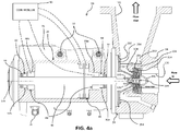
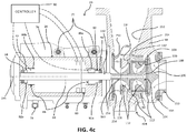
- turbine 24 is an overhung axial turbine and includes a housing 98 having an axial inlet 100 and a radial outlet 102.
- Turbine 24, in one embodiment, is a multi-stage turbine, with the embodiment shown in FIG. 4a having three stages. In other examples discussed more below, turbine 24 may be a single-stage overhung radial turbine as show in FIG. 4b , and a multi-stage overhung radial turbine as shown in FIG. 4c .
- turbine 24 is constructed so that the working fluid is expanded as it is transported through the turbine, with the result that the cold end of the turbine, i.e., the end proximate radial outlet 102, is positioned adjacent generator 26. This arrangement reduces heat transfer from turbine 24 to generator 26.
- Turbine 24 includes a turbine rotor 104 that rotates about rotational axis 106 and a stator 108 that is fixed with respect to housing 98.
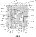
- turbine rotor 104 includes a plurality of individual bladed plates 110 and stator 108 includes a plurality of individual plates 112 positioned in alternating, inter- digitated relationship with the rotor plates, as best seen in FIGS. 5 , 6 and 9 .
- Rotor plates 110 and stator plates 112 are positioned within housing 98 in the cavity 114 formed at the region between inlet 100 and outlet 102. As best illustrated in FIGS.
- stator plates 112 are spaced from portions of turbine rotor 104 positioned between rotor plates 110 so as to form a gap 115 sealed by seals 116 provided on such radially innermost portion of the stator plates.
- a plurality of stator spacer segments 117 one corresponding to each rotor plate 110, is provided in alternating, inter-digitated relationship with radially outer portions of stator plates 112. Each spacer segment 117 is positioned radially outwardly of a corresponding respective rotor plate 110.
- spacer segments 117 are formed as an integral portion of stator plates 112 (spacer segments are not separately labeled in FIGS. 9 and 10 ).
- each spacer segment 117 is sized with respect to its corresponding respective rotor plate 110 so that a gap 118 is provided between a radially outermost portion of the rotor plate and the radially innermost portion of the spacer segment.
- Seals 119 may be provided in gap 118 in certain embodiments of turbine 24.
- each rotor plate 110 includes a first contact surface 130 and a second contact surface 132 that contacts the first contact surface.
- each stator plate 112 includes a first contact surface 134 and a second contact surface 136 that contacts the first contact surface.
- Contact surfaces 130, 132, 134 and 136 are substantially flat and substantially parallel. Further, they are arranged to be substantially perpendicular to rotational axis 106. In one embodiment, contact surfaces 130, 132, 134 and 136 are flat in the range 0.00127mm to 0.508mm (0.00005" to 0.020"), and in certain embodiments in the range 0.00127mm to 0.127mm (0.0005" to 0.005"), as measured with respect to a root mean square version of such surfaces.
- contact surfaces 130 and 132 of rotor plates 110, and contact surfaces 134 and 136 of stator plates 112 deviate from perfectly parallel by an amount in the range 0.00254mm to 0.381mm (0.0001" to 0.015"), and in certain embodiments in the range 0.00127mm to 0.127mm (0.0005" to 0.005").
- Spacer segments 117 when provided, preferably have contact surfaces that are similarly flat and parallel to contact surfaces 130, 132, 134, and 136, as discussed above.
- turbine 24 it may be desirable to circumferentially clock one rotor plate 110 with respect to an adjacent rotor plate, e.g., clocking rotor plate 110a with respect to plate 110b. Similarly, it may be desirable to circumferentially clock one stator plate 112 with respect to an adjacent stator plate, e.g., clocking stator plate 112a with respect to plate 112c. Desired performance specifications for turbine 24 will influence the extent of clocking provided, as those skilled in the art will appreciate.
- a first rotor plate 110 e.g., plate 110a
- a second adjacent rotor plate e.g., plate 110b
- zero to one vane pitch i.e., (0)S to (1)S.
- a first stator plate 112 e.g., plate 112a is clocked with respect to an adjacent stator plate, e.g., plate 112c , zero to one vane pitch, i.e., (0)S to (1)S.
- a first rotor plate 110 e.g., plate 110a
- a second adjacent rotor plate e.g., plate 110b
- a first stator plate 112 e.g., plate 112a
- an adjacent stator plate e.g., plate 112c
- Known turbine flow analytical and experimental methods are used to guide selection of the optimal amount of clocking in this range of 0 to 360 degrees.
- adjacent stator plates 112 are clocked with respect to one another using an alignment system featuring a plurality of circumferentially spaced bores 160 positioned along a peripheral section 162 of a stator plate 112, e.g., stator 112c, only five of which are illustrated in FIG. 7 for convenience of illustration.
- adjacent bores 160 are circumferentially spaced one vane pitch S.
- the alignment system also includes a bore 164 in a peripheral section 166 of spacer segments 117.
- a blind bore 168 may be provided in a peripheral section 170 of a stator plate 112, e.g., stator plate 112a, immediately adjacent the stator plate, e.g., stator plate 112c, in which bores 160 are provided (rotor plate 110b and spacer plate 117 are intervening, of course).
- bores 160, 164 and 168 are spaced a substantially identical radial distance from rotational axis 106, and have a substantially identical diameter.
- the alignment system further includes pin 172, which is sized for receipt, typically using a mild friction fit, in a selected one of bores 160 and in bore 164.
- pin 172 locks stator plate 112c in selected circumferential alignment with adjacent spacer segment 117.
- the selected circumferential clocking between adjacent stator plates, e.g., plates 112a and 112c, is achieved by next locking spacer section 117 to stator plate 112a using pin 174 inserted in bores 164 and 168.
- a similar system for clocking adjacent rotor plates 110 may also be employed, as discussed more below in connection with FIGS. 9 and 10 .
- selection of one of the plurality of bores 160 that receives pin 172 is determined based on the extent of circumferential clocking desired between adjacent stator plates 112.
- the present invention encompasses other approaches to circumferentially clocking adjacent rotor plates 110 and stator plates 112, as those skilled in the art will appreciate.
- rotor plates 110 and stator plates 112 are, in one implementation, spaced so that axial distance 178 between vanes 140 of a rotor plate 110 and vanes 142 of an adjacent stator plate 112 is in the range of two axial chords to 1/4 of 1% of an axial chord, and in certain embodiments 1/3 to 1 chord, as measured with respect to the chord of the immediately upstream one of the rotor or stator plates.
- stage reaction for turbine 24 may be of any conventional level.
- very low stage reaction may be desirable, with common values in one example ranging from -0.1 to 0.3 and often falling in the range of -0.05 to +0.15.
- very low stage reaction cannot be achieved, for example with multi-stage radial inflow turbine 424 illustrated in FIG. 4c , then the second stage may be reversed so that the two radial turbines work back-to-back, leaving the last stage discharge still facing the generator.
- rotor plates 110 and stator plates 112 are positioned in alternating, inter-digitated relationship.
- rotor plates 110 include a plurality of bores 186 (see FIG. 5 ) in radially inner portions of the plates, which bores are sized to receive a fastener, such as bolt stud 188, which extends through the plates and is secured to stub shaft 189 via threaded bores 190 in the stub shaft.
- Generator rotor shaft 93 may include a threaded male end 192 that is received in a threaded bore 194 in stub shaft 189.
- Stator plates 112, and spacer segments 117 if provided may, for example, be secured together in alternating, inter-digitated relationship so as to form a unitary cartridge 198.
- the latter may be releasably secured in cavity 114 ( FIG. 6 ) of housing 98 using known fasteners and other devices.
- cartridge 198 may be secured in cavity 114 by lock ring 200, which is engaged with a snap fit in a correspondingly sized recess 201 in in the cavity.
- rotor plates 110 may be secured together with pins 203 (see FIGS. 9 and 10 ) received in bores 204 (see FIGS. 8 , 9 and 10 ) to ensure no relative rotational movement occurs between rotor plates.
- stator plates 112 and spacers 117 may be secured together with pins 172 (see FIGS. 9 and 10 ), as discussed above, to ensure no relative rotational movement occurs.
- Pins 172 may also penetrate into floor 204 of housing 98 (such penetration not being shown) from the downstream- most spacer 117 or stator plate 112, if desired to assure no relative motion.
- a nose cone 206 may be provided, with one embodiment being threadedly engaged with threaded bore 208 in the furthest upstream stator plate 112 (identified in FIGS. 9 and 10 as S1). Alternatively, machine screws may be used to fasten nose cone 206 to first stator plate 112. With reference to FIGS. 5 , 6 , 9 and 10 , in some implementations it may be desirable to rotationally align and secure together rotor plates 110, stator plates 112, and if provided, spacers 117, using one or more pins 210 and/or one or more bolt studs 212 that extend through the rotor plates, stator plates and spacers.
- Pins 210 may be used for precision rotational alignment of rotor plates 110, stator plates 112 and spacers 117, and if received in these components with a sufficient force fit, may also hold these components together to form a unitary structure, namely unitary cartridge 198.
- Bolt studs 212 in addition to providing some measure of rotational alignment, also draw together the rotor plates, stator plates and spacers to form a unitary structure, namely unitary cartridge 198.
- cartridge 198 By providing separate rotor plates 110 and stator plates 112, and by making such plates relatively flat as discussed above, these plates may be assembled as a cartridge 198 (see FIG. 5 ) that may be positioned in and removed from cavity 114 in housing 98 as a unitary assembly. As discussed more below, the provision of cartridge 198 permits a universal turbine 24 to be readily adapted for its intended application and interchanged for maintenance or new loading requirements.
- seal 220 surrounding stub shaft 189 of turbine 24 proximate the radially innermost portion of backplate 250.
- Seal 220 may be implemented as a labyrinth seal, a brush seal, a close-tolerance ring seal or using other seals known in the art.
- turbine 24 shown in FIGS. 4-6 is designed to permit ready manufacture of versions of the turbine having differently sized rotors 104 and stators 108.
- the turbine can be manufactured on a cost-efficient basis to the specifications of a given application.
- This flexible design is achieved in part by designing and sizing housing 98 of turbine 24 so that the largest-diameter turbine rotor 104 contemplated for the turbine may be received within cavity 114 and through the use of the cartridge design discussed above.
- the desired operating parameters of turbine 24 are determined for the application in which the turbine will be used, then the number and size of plates 110 used in turbine rotor 104, and plates 112 and spacer segments 117 used in stator 108, are determined.
- housing 98 is designed to facilitate such modification.
- One aspect of such design of housing 98 involves providing floor 204 with a thickness sufficient to accommodate turbine rotor 104 and stator 106 having varying radial heights. ⁇ r, as measured between said rotational axis and an outermost portion of said at least one turbine rotor, said axial turbine including a hood having a floor with a first thickness, wherein said first thickness is selected to permit said floor to be machined on the inside to a thickness sufficient to accommodate said at least one turbine rotor with a radial dimension that varies between ⁇ r and 1.4 ⁇ r.
- housing 98 is provided with a configuration that permits easy access to floor 204 by conventional machine tools, e.g., a 5-axis CNC milling machine or a CNC lathe, that can be used to machine the floor so as to create a cavity 114 sized to receive turbine rotor 104 and stator 106 with the desired radial heights.
- machine tools e.g., a 5-axis CNC milling machine or a CNC lathe, that can be used to machine the floor so as to create a cavity 114 sized to receive turbine rotor 104 and stator 106 with the desired radial heights.
- a modifiable housing 98 is to include a backplate 250 having a thickness that may be adjusted so as to selectively vary width l 4, i.e., the distance l 4 between backplate 250 and housing wall 252, and to selectively vary width l 1 , i.e., the exit width.
- width l 4 may be varied so that it ranges from one half to four times the width of diffuser exit l 1.
- Backplate 250 may be an integral portion of housing 98 in some embodiments and a separate element in others, as illustrated in FIG. 4 .
- Backplate 250 preferably includes one or more ports 254 through which vapor in gap 70 may be exhausted and delivered to the exhaust flow path of turbine 24 and ultimately via fluid connection 34 to condenser 36.
- flow splitter 256 may be provided immediately downstream of turbine rotor 104 and stator 106 as another way to tailor the performance of turbine 24.
- an extension plate 258 may be added to nose 260 of floor 204 of housing 98, as best seen in FIG. 6 .
- Housing performance depends on several factors, but alignment of the entry flow at the housing inlet 100 and housing base dimensions are important as taught in the literature.
- a very good flow entry provides for diffuser exhaust flowing up the housing backplate 250, as configured in FIG. 4 .
- the exit width l 1 also controls the performance of the diffuser as it controls the diffuser overall area ratio, which is a first order design parameter; hence a conflict can arise. If l 1 is increased for the diffuser, it will hurt the housing.
- Turbine 24 is depicted in FIG. 4a as a multi-stage axial turbine 24, but turbine-generator system 20 is not so limited.
- turbine-generator system 20 may include a radial turbine 324 having a single stage.
- radial turbine 324 having a single stage.
- the latter includes a single rotor 104 and a single stator 108.
- radial turbine 324 may be implemented as a unitary cartridge 198 that may be releasably secured to generator shaft 93 with a bolt stud 188.
- Turbine 324 may include an inlet flange ring 333, and an outer flow guide 334 attached to housing 98 with known fasteners.
- Nose cone 206 and stator 108 may be releasable secured to housing 98 with a known fastener, such as bolts 337.
- turbine-generator system 20 may include a multi-stage radial turbine 424.
- radial turbine 424 may be implemented as a unitary cartridge 198 that may be releasably secured to generator shaft 93 with a bolt stud 188.
- Turbine 424 may include an inlet flange ring 333, and an outer flow guide 334 attached to housing 98 with known fasteners.
- Nose cone 206 and stators 108, together with intermediate flow guide 441 positioned between the stators, may be releasable secured to housing 98 with a known fastener, such as bolts 337.
- the two stators 108 of turbine 424 and intermediate flow guide 441 may be secured together with bolts 339 or other known fasteners so as to create unitary cartridge 198.
- Intermediate flow guide 441 is functionally analogous to stator spacers 117 in the version of turbine 24 illustrated in FIGS. 5 and 6 .
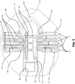
- rotors 104 of a multi-stage radial turbine in a back-to-back arrangement, as illustrated in FIG. 4d with respect to radial turbine 524.
- rotor 104a is positioned so it backs up to rotor 104b, with the rotors being coupled to rotate together.
- Stator 108 is positioned between rotors 104a/104b, and includes bearings 526 for rotatably supporting a portion of rotor 104b that extends through the stator.
- Turbine 524 further includes a front face plate 550 through which gas transfer tubes 552 extend, with the gas transfer tubes terminating at interior plenum 554. Gas flow entering turbine 524 flows into tubes 552, is delivered to interior plenum 554, exits the plenum causing rotor 104a to rotate, flows over stator 108, then drives rotor 104b and finally exits the turbine..
- turbine-generator system 20 may also be implemented using a mixed-flow turbine.
- the latter is very similar in design to radial turbine generators 324 and 424, and so is not separately illustrated.
- the system includes an electric generator having a power output of 5MW or less, said generator having a proximal end, a distal end, a generator rotor and a stator, said generator rotor being disposed for rotational movement within said stator about a rotational axis, said generator also including a first fluid film bearing positioned adjacent said proximal end, and a second fluid film bearing positioned adjacent said distal end, said first and second fluid film bearings surrounding said generator rotor and retaining said generator rotor, during operation, in substantially coaxial alignment with respect to said rotational axis; and a turbine having at least one stator and at least one turbine rotor supported for rotational movement relative to said at least one stator about said rotational axis, said at least one turbine rotor being coupled with said generator rotor so as to rotationally drive said generator rotor, said turbine having a first end attached to said proximal end of said generator, wherein said at least one turbine rotor
- system described in paragraph 48 has an electric generator with a power output of less than 600 KW.
- the turbine of the system described in paragraph 48 may, in one example, include a housing, and the at least one stator may include a plurality of stator plates, and the at least one turbine rotor may include a plurality of turbine rotor plates, further wherein the plurality of stator plates and the plurality of turbine rotor plates together form a unitary cartridge that is releasably mounted in said housing.
- the turbine of the system described in paragraph 48 may be an axial turbine, a radial turbine or a mixed-flow turbine.
- the system described in paragraph 48 may include a hood having a removable backplate with a surface, a hood wall opposite the backplate, and a diffuser passage exit having a width l 1, wherein the backplate surface is spaced a distance l 4 from the hood wall, wherein the distance l 4 ranges between one half and four times the distance l 1.
- the cartridge consists of a plurality of rotor plates, each having a centerline, a first contact surface and a second contact surface contacting said first contact surface, said first and second contact surfaces being substantially parallel and each of said first and second contact surfaces being flat in the range 0.00127mm to 0.508mm (0.00005" to 0.020"), wherein said plurality of rotor plates are positioned proximate one another so that said centerlines of said rotor plates are mutually coaxial; a plurality of stator plates, each having a centerline, a first contact surface and a second contact surface contacting said first surface, said first and second contact surfaces being substantially parallel and each of said first and second contact surfaces being flat in the range 0.00127mm to 0.508mm (0.00005" to 0.020"), wherein said plurality of stator plates are positioned proximate one another so that said centerlines of said stator plates are mutually co-axial; and wherein said plurality of rotor plates are positioned in
- the space in the turbine cartridge described in paragraph 53 has an axial dimension that ranges from 1/3 to 1 of said axial chord of the one of said rotor plate and stator plate immediately upstream of said space.
- said plurality of rotor plates are secured with respect to one another and said plurality of stator plates are secured with respect to one another and positioned relative to said plurality of rotor plates so as to form a unitary cartridge system.
- said unitary cartridge system is designed to be releasably coupled to a turbine housing.
Description
- The present invention generally relates to the field of turbine generator power systems for industrial waste heat recovery and other applications. In particular, the present invention is directed to an overhung axial turbine.
- Concerns about climate change and rising energy costs, and the desire to minimize expenses in various industrial operations, together lead to an increased focus on capturing waste heat developed in such operations. Organic Rankine Cycle ("ORC") turbine generator electrical power systems have been used in industrial waste heat recovery. Unfortunately, known systems for capturing waste heat and converting it to electricity are often too large for the space available in certain industrial operations, are less efficient than desired, require more heat to operate efficiently than is available, are too expensive to manufacture for certain applications, or require more maintenance than is desired. In other applications, such as geothermal energy recovery and certain ocean thermal energy projects, abundant heat is available and an efficient ORC system is a satisfactory means for conversion of such heat to electricity. Even in such other applications, however, known ORC systems tend to be too expensive for some such applications, are less efficient than desired and/or require more maintenance than is desired.
-
WO2011/149916 discloses an apparatus including an electric generator having a stator and a rotor which generates an energy from fluid expansion. DocumentGB 373010A - According to the invention, there is provided an overhung axial turbine according to claim 1.
- It should be understood that the present invention is not limited to the precise arrangements and instrumentalities shown in the drawings, wherein:
-
FIG. 1 is a schematic depiction of an ORC turbine-generator system; -
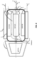
FIG. 2 is a schematic depiction of the turbine and generator of the system shown inFIG. 1 , with interior details of the generator being schematically illustrated; -
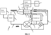
FIG. 3 is similar toFIG. 1 , except that an alternative example of the ORC turbine-generator system is depicted; -
FIG. 4a is a cross-sectional view of a multi-stage axial turbine embodiment of the turbine assembly depicted inFIG. 1 and a partially broken-away view of the generator depicted inFIG. 1 showing, schematically, bearings included in one embodiment of the generator, with the rotor and stator of the generator removed for clarity of illustration; -
FIG. 4b is similar toFIG. 4a , except that a single-stage radial turbine example of the turbine assembly depicted inFIG.1 is shown; -
FIG. 4c is similar toFIG. 4b , except that a multi-stage radial turbine example of the turbine assembly depicted inFIG. 4b is shown; -
FIG. 4d is similar toFIG. 4c , except that the rotors of the multi-stage radial turbine assembly depicted inFIG. 4c are arranged in back-to-back configuration -
Figures 4b-4c disclose non claimed arrangements. -
FIG. 5 is cross-sectional view of one embodiment of a turbine cartridge usable in the turbine shown inFIG. 4a ; -
FIG. 6 is an enlarged cross-sectional view of a portion of the turbine shown inFIG. 4a , illustrating a portion of the hood backplate and the entire turbine cartridge; -
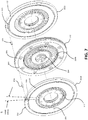
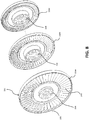
FIG. 7 is a perspective view showing the relative placement of two stator plates and one rotor plate with its stationary spacer plate used in a multi-stage embodiment of the turbine depicted inFIG. 4a ; -
FIG. 8 is a perspective view of three rotor plates used in a multi-stage embodiment of the turbine depicted inFIG. 4a showing the relative placement of the plates; -
FIG. 9 is a cross-sectional side view of a portion of the turbine shown inFIG. 6 illustrating brush seals and other details of the turbine; and -
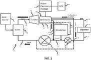
FIG. 10 is similar toFIG. 9 , except that it depicts an alternative embodiment of the turbine. - The present disclosure is directed to a turbine powered electrical generator for use in an Organic Rankine Cycle (ORC), Kalina cycle, or other similar cycles, industrial operations that generates waste heat, or in connection with other heat sources, e.g., a solar system or an ocean thermal system. High-pressure hot gas from a boiler, which is heated by the heat source, enters the turbine housing and is expanded through the turbine to turn the rotor, which turns the generator shaft to generate electricity, as described more below.
- Referring to
FIG. 1 , turbine-generator assembly 20 is intended for use in anORC system 22. For convenience of discussion,system 22 is referred to and described asORC system 22. It is, however, to be appreciated that other thermodynamic processes, such as a Kalina cycle process and bottoming cycle processes, are also encompassed by the present invention. Turbine-generator assembly 20 includes aturbine 24 and agenerator 26 connected to, and driven by, the turbine. Before discussing turbine-generator assembly 20 in more detail, discussion ofORC system 22 is provided. - ORC
system 22 includes aboiler 28 that is connected to aheat source 30, such as waste heat from an industrial process. Boiler 28 provides high-pressure hot vapor viaconnection 32 toturbine 24. As discussed more below, the hot vapor, aka, the working fluid, is expanded inturbine 24, where its temperature drops, and is then exhausted from the turbine and delivered viafluid connection 34 to condenser 36. Incondenser 36, the vapor cooled inturbine 24 is cooled further, typically to a liquid state, and then a first volume of such liquid is delivered viafluid connection 38 topump 40, where the liquid is returned viaconnection 42 toboiler 28. This liquid is then reheated inboiler 28 by heat fromheat source 30 through a heat exchanger or other structure (none shown) in the boiler and then, repeating the cycle, is returned as high-pressure hot vapor viafluid connection 32 toturbine 24. - Turning now to
FIGS. 1 and2 , a second volume of the cooledliquid exiting condenser 36 is, in one example, delivered bypump 50 viafluid connection 52 tovaporizer 54 and from the vaporizer togenerator 26 viafluid connection 58. Fluid frompump 50 is also delivered viafluid connection 56 togenerator 26, inparticular cooling jacket 76, discussed more below. In other examples, it may be desirable to omitpump 50 and instead deliver liquid that is output frompump 40 viafluid connection 57 tofluid connections condenser 36 and delivers the cooling vapor viafluid connection 58 togenerator 26. As illustrated inFIG. 2 ,generator 26 includes afluid gap 70, astator 72 and agenerator rotor 74, with the fluid gap (e.g., gas or atomized liquid) being positioned between the stator and rotor.Generator rotor 74 rotates relative tostator 72 aboutrotational axis 106. - The cooling vapor is introduced into
gap 70, and as the vapor passes throughgap 70 it extracts heat fromstator 72 andgenerator rotor 74, which vapor is then exhausted viafluid connection 34, along with the hot vapor exhausted fromturbine 24, for cooling bycondenser 36. Optionally, as illustrated inFIGS. 1 and3 , vapor exhausted fromgenerator 26 may be delivered viafluid connection 37 directly tocondenser 36 rather than being combined with vapor exhausted fromturbine 24. Turbine 24 has a through flow rate and, in one example, the second volume of the vapor (working fluid) introduced intogap 70 travels through the gap with a flow rate that is no more than 50% of the through flow rate. Typically, although not necessarily,generator 26 is hermetically sealed to ensure working fluid present ingap 70 does not escape except viafluid connection 34, orfluid connection 37, if provided. - Referring now to
FIGS. 1-4 , in oneexample generator 26 is surrounded by a cooling jacket 76 (FIGS. 2 and4 ) for cooling the generator. Cooling liquid pumped bypump 50 togenerator 26 viafluid connection 56 is delivered to coolingjacket 76 via inlets 77 (FIG. 4 ). As the cooling liquid circulates through coolingjacket 76, it extracts heat fromstator 72 and other components ofgenerator 26. After completing its passage through coolingjacket 76, the cooling liquid, now somewhat hotter, is removed fromgenerator 26 viafluid connection 78, after exitingfluid outlet 79 in the cooling jacket, and returned tocondenser 36. - Turning next to
FIGS. 2 and3 , in another example ofORC system 22, atomized cooling liquid, rather than vaporized liquid, is provided togap 70 ingenerator 26. Except as specifically discussed below, the example ofORC system 22 illustrated inFIG. 3 is essentially identical to the example of the system shown inFIG. 1 , and so description of identical elements is not provided in the interest of brevity. Unlike the example ofORC system 22 illustrated inFIG. 1 , no vaporizer is provided in the example illustrated inFIG. 3 . Instead a portion of the cooling liquid delivered viafluid connection 56 togenerator 26 is provided byfluid connection 80 toatomizer 82 positioned proximate to the generator.Atomizer 82 atomizes the cooling liquid, which is then delivered togap 70 ingenerator 26, where the relatively cool atomized liquid extracts heat fromstator 72 andgenerator rotor 74 as it travels through the gap, including through the latent heat of vaporization with respect to portions of the atomized liquid that are vaporized by the heat in the stator and rotor. The atomized liquid is then extracted fromgenerator 26 viafluid connection 34 along with the working fluid exhausted fromturbine 24. InFIGS. 2 and3 ,atomizer 82 is depicted in dotted view to indicate that it is an optional element used in connection with one example of the invention. As discussed above, in one example, the second volume of the atomized liquid (working fluid) introduced intogap 70 travels through the gap with a flow rate that is no more than 50% of the through flow rate ofturbine 24. - In some applications, it may be desirable to provide just cooling of
stator 72 via coolingjacket 76, and not provide vapor or atomized liquid togap 70. In other applications, the reverse may be desired. - Various high molecular weight organic fluids, alone or in combination, may be used as the working fluid in
system 20. These fluids include refrigerants such as, for example, R125, R134a, R152a, R245fa, and R236fa. In other applications fluids other than high molecular weight organic fluids may be used, e.g., water and ammonia. -
System 22 also includes apower electronics package 86 connected togenerator 26.Package 86 converts the variable frequency output power fromgenerator 86 to a frequency and voltage suitable for connection to thegrid 87, e.g. 50 Hz and 400 V, 60 Hz and 480 V or other similar values. - Discussing
generator 26 in more detail, in one example the generator is a direct-drive, permanent magnetic, generator. Such a construction is advantageous because it avoids the need for a gearbox, which in turn results in a smaller andlighter system 20. Various aspects of the invention described herein may, of course, be effectively implemented using a generator having a gearbox mechanically coupled betweenturbine rotor 104 ofturbine 24 andgenerator rotor 74 ofgenerator 26, and a suitable wound rotor that does not include permanent magnets, e.g., a doubly wound, induction-fed rotor. In addition, in certain applications direct-drive synchronous generators may be used asgenerator 26. The rated power output ofgenerator 26 will vary as a function of the intended application. In one example,generator 26 has a rated power output of 5MW. In another example,generator 26 has a rated power output of 50KW, and in yet other example,generator 26 has a rated power output somewhere in between these values, e.g., 200KW, 475KW, 600KW, or 1MW. Rated power outputs forgenerator 26 other than those listed in the examples above are encompassed by the present invention. - To permit high-speed (e.g., on the order of 20,000-25,000 rpm) operation, and to minimize maintenance, it may be desirable in some examples of
generator 26 to supportgenerator rotor 74 for rotational movement using magnetic radial bearings 88 (seeFIG. 4 ). In one example, magneticradial bearing 88a is positioned adjacent an end ofgenerator rotor 74proximate turbine 24 and magnetradial bearing 88b is positioned adjacent an opposite end of the rotor. As discussed more below, this placement ofbearings 88 enables in large part the overhung construction ofturbine 24. Similarly, axial movement ofgenerator rotor 74 may be controlled through the use of magneticaxial thrust bearing 89. Magneticradial bearings 88 and magnetic axial thrust bearing 89 are controlled by acontroller 90 that adjusts power delivered to the bearings as a function of changes in radial and axial position ofgenerator rotor 74, as detected by sensors (not shown) coupled to the controller, all as well known to those of ordinary skill in the art. - In another embodiment of the invention, fluid-film bearings may be used in place of magnetic
radial bearings 88 and thrustbearing 89. For purposes of illustration, the schematic depiction ofmagnetic bearings FIG. 4 should be deemed to include, in the alternative, fluid-film bearings. As is known, fluid-film bearings support the total rotor load on a thin film of fluid, i.e., gas or liquid. - Optionally, in addition to
magnetic bearings radial bearings 92, e.g.,radial bearings rotor shaft 93 ofgenerator rotor 74 surrounding the rotor shaft, typically adjacentmagnetic bearings radial bearings 92support generator rotor 74 and itsshaft 93 in substantially coaxial relation torotational axis 106 whenmagnetic bearings radial bearings 92 provide a rest point forgenerator rotor 74 whenmagnetic bearings 88 are not activated and provide a safe landing for the generator rotor in the event of a sudden electronic or power failure. It may be desirable in some cases to size rolling elementradial bearings 92 to supportgenerator rotor 74 with a relatively loose fit so that during operation whenmagnetic bearings radial bearings 92, even during times of maximum radial deflections ofgenerator rotor 74 due to perturbations in the operation ofmagnetic bearings 88. When fluid-film bearings are used in place of magneticradial bearings 88, rolling elementradial bearings 92 are typically not required, although in some applications it may be desirable to include such radial bearings. - In one example, rolling element
radial bearings 92 are sized to permitrotor shaft 93 to deviate radially from perfect coaxial alignment withrotational axis 106 an amount that is 1.01 to 5 times as great as the maximum radial deviation ofshaft 93 fromrotational axis 106 that may occur when magneticradial bearings 88 are fully activated, including during times of major radial deflection that may occur due to perturbations of the magnetic radial bearings, e.g., from a fluid dynamic instability or a failed control system or a power failure (without backup). In anotherexample, this deviation permitted byradial bearings 92 is about 2 to 3 times as great as the radial deviation ofshaft 93 fromrotational axis 106 that occurs whenmagnetic bearings 88 are activated , again including during major perturbations that occur over time. Rolling elementradial bearings 92 are often referred to as "bumper bearings" or "backup bearings" in the art. - While beneficial for the reasons discussed above, rolling element
radial bearings 92 also present a challenge because the radial clearance of such bearings is much higher than the desired clearances for the conventional seals (not shown in detail) ofturbine 24. Typical rolling elementradial bearings 92 have a radial clearance on the order of 0.00127mm to 0.381mm (0.005 to 0.015 inch). By contrast, desired radial clearances for the seals ofturbine 24 are typically on the order of 0 to 0.0254 (0.000 - 0.001 inch). Asgenerator 26 is assembled, shipped and stored, or during a loss of levitation ofgenerator rotor 74 during operation due to failure ofmagnetic bearings 88, the generator rotor will drop to rolling elementradial bearings 92. A consequence of such "play" ingenerator rotor 74 is that portion ofshaft 93 proximate rolling elementradial bearings 92, along with seals inturbine 24, can be damaged over time. Indeed, in certain applications, as few as 1-10 "bumper" events can cause sufficient damage to components of turbine-generator assembly 20 that disassembly and repair/replacement of such components is required. - A solution to this problem is to add a radial brush seal 94 (
FIG. 4 ) adjacent one or more ofmagnetic bearings 88 and/or rolling elementradial bearings 92, or to substitute a brush seal for the rolling element radial bearings (i.e., the bumper bearings). As used in such context,brush seal 94 is designed to withstand substantial radial forces before deforming. Such deformation is temporary, withbrush seal 94 being constructed so that it springs back quickly to its prior configuration. In other words,brush seal 94 is self-healing. The stiffness of eachbrush seal 94 is selected based upon the weight ofgenerator rotor 74 and turbine rotor 104 (discussed below) coupled with the generator rotor, and the extent of radial movement of therotors generator 26 andturbine 24. In oneexample, the stiffness of brush seals 94 is selected so that the extent of radial deviation ofgenerator rotor 74 from co-axial alignment withrotational axis 106 that occurs when the rotor is supported by just the brush seals is 1 to 5 times greater than the extent of maximum radial deviation ofgenerator rotor 74 from co-axial alignment withrotational axis 106 that occurs whenmagnetic bearings 88 are fully activated and supportinggenerator rotor 74 for rotational movement through the course of normal operation. In another example, such extent of radial deviation is 1.2 to 4 times greater than the extent of radial deviation ofgenerator rotor 74 from co-axial alignment withrotational axis 106 that occurs whenmagnetic bearings 88 are fully activated and supportinggenerator rotor 74 for rotational movement through the course of normal operation. In another implementation,generator rotor 74 is free to move a first radial distance out of co-axial alignment withrotational axis 106 whenmagnetic bearings 88 are not activated and the generator rotor does not move radially more than a second radial distance out of co-axial alignment with rotation axis when supported by brush seals 94. In this implementation, the second radial distance is no more than 0.8 times the first radial distance, and in some implementations ranges from 0.2 to 0.6 times the first radial distance. - Referring now to
FIGS. 2 and4-10 ,turbine 24 will be described in more detail. In the embodiment illustrated inFIG. 4a ,turbine 24 is an overhung axial turbine and includes ahousing 98 having anaxial inlet 100 and aradial outlet 102.Turbine 24, in one embodiment, is a multi-stage turbine, with the embodiment shown inFIG. 4a having three stages. In other examples discussed more below,turbine 24 may be a single-stage overhung radial turbine as show inFIG. 4b , and a multi-stage overhung radial turbine as shown inFIG. 4c . Consistent with this overhung configuration, no radial bearings are included inturbine turbine 24 is constructed so that the working fluid is expanded as it is transported through the turbine, with the result that the cold end of the turbine, i.e., the end proximateradial outlet 102, is positionedadjacent generator 26. This arrangement reduces heat transfer fromturbine 24 togenerator 26. -
Turbine 24 includes aturbine rotor 104 that rotates aboutrotational axis 106 and astator 108 that is fixed with respect tohousing 98. As discussed more below, in one example ofturbine 24 featuring a modular design,turbine rotor 104 includes a plurality of individualbladed plates 110 andstator 108 includes a plurality ofindividual plates 112 positioned in alternating, inter- digitated relationship with the rotor plates, as best seen inFIGS. 5 ,6 and9 .Rotor plates 110 andstator plates 112 are positioned withinhousing 98 in thecavity 114 formed at the region betweeninlet 100 andoutlet 102. As best illustrated inFIGS. 9 and10 , radially innermost portions ofstator plates 112 are spaced from portions ofturbine rotor 104 positioned betweenrotor plates 110 so as to form agap 115 sealed byseals 116 provided on such radially innermost portion of the stator plates. In the portion ofturbine 24 illustrated inFIG. 5 , a plurality ofstator spacer segments 117, one corresponding to eachrotor plate 110, is provided in alternating, inter-digitated relationship with radially outer portions ofstator plates 112. Eachspacer segment 117 is positioned radially outwardly of a correspondingrespective rotor plate 110. In the alternative embodiments ofturbine 24 illustrated inFIGS. 9 and10 ,spacer segments 117 are formed as an integral portion of stator plates 112 (spacer segments are not separately labeled inFIGS. 9 and10 ). In any event, in each of these embodiments, eachspacer segment 117 is sized with respect to its correspondingrespective rotor plate 110 so that agap 118 is provided between a radially outermost portion of the rotor plate and the radially innermost portion of the spacer segment. Seals 119 (seeFIG. 9 ) may be provided ingap 118 in certain embodiments ofturbine 24. - As best illustrated in
FIGS. 9 and10 , eachrotor plate 110 includes afirst contact surface 130 and asecond contact surface 132 that contacts the first contact surface. Similarly, eachstator plate 112 includes afirst contact surface 134 and asecond contact surface 136 that contacts the first contact surface. Contact surfaces 130, 132, 134 and 136 are substantially flat and substantially parallel. Further, they are arranged to be substantially perpendicular torotational axis 106. In one embodiment, contact surfaces 130, 132, 134 and 136 are flat in the range 0.00127mm to 0.508mm (0.00005" to 0.020"), and in certain embodiments in the range 0.00127mm to 0.127mm (0.0005" to 0.005"), as measured with respect to a root mean square version of such surfaces. Further, in one embodiment contact surfaces 130 and 132 ofrotor plates 110, andcontact surfaces stator plates 112, deviate from perfectly parallel by an amount in the range 0.00254mm to 0.381mm (0.0001" to 0.015"), and in certain embodiments in the range 0.00127mm to 0.127mm (0.0005" to 0.005").Spacer segments 117, when provided, preferably have contact surfaces that are similarly flat and parallel to contactsurfaces - Referring now to
FIGS. 7 and8 , in certain implementations ofturbine 24, it may be desirable to circumferentially clock onerotor plate 110 with respect to an adjacent rotor plate, e.g., clockingrotor plate 110a with respect toplate 110b. Similarly, it may be desirable to circumferentially clock onestator plate 112 with respect to an adjacent stator plate, e.g., clockingstator plate 112a with respect toplate 112c. Desired performance specifications forturbine 24 will influence the extent of clocking provided, as those skilled in the art will appreciate. When pairs ofrotor plates 110 being clocked both have an equal number ofvanes 140, in one embodiment afirst rotor plate 110, e.g.,plate 110a, is clocked with respect to a second adjacent rotor plate, e.g.,plate 110b, zero to one vane pitch, i.e., (0)S to (1)S. Similarly, when pairs ofstator plates 112 being clocked both have an equal number ofvanes 142, in one embodiment afirst stator plate 112, e.g.,plate 112a is clocked with respect to an adjacent stator plate, e.g.,plate 112c , zero to one vane pitch, i.e., (0)S to (1)S. When pairs ofrotor plates 110 being clocked both have an unequal number ofvanes 140, in one embodiment afirst rotor plate 110, e.g.,plate 110a, is clocked with respect to a second adjacent rotor plate, e.g.,plate 110b, somewhere in the range of 0 to 360 degrees. Similarly, when pairs ofstator plates 112 being clocked both have an unequal number ofvanes 142, in one embodiment afirst stator plate 112, e.g.,plate 112a is clocked with respect to an adjacent stator plate, e.g.,plate 112c, somewhere in the range of 0 to 360 degrees. Known turbine flow analytical and experimental methods are used to guide selection of the optimal amount of clocking in this range of 0 to 360 degrees. - With continuing reference to
FIGS. 7 and8 , in one embodimentadjacent stator plates 112 are clocked with respect to one another using an alignment system featuring a plurality of circumferentially spacedbores 160 positioned along aperipheral section 162 of astator plate 112, e.g.,stator 112c, only five of which are illustrated inFIG. 7 for convenience of illustration. In one implementation,adjacent bores 160 are circumferentially spaced one vane pitch S. The alignment system also includes abore 164 in aperipheral section 166 ofspacer segments 117. Further, ablind bore 168 may be provided in aperipheral section 170 of astator plate 112, e.g.,stator plate 112a, immediately adjacent the stator plate, e.g.,stator plate 112c, in which bores 160 are provided (rotor plate 110b andspacer plate 117 are intervening, of course). In one embodiment, bores 160, 164 and 168 are spaced a substantially identical radial distance fromrotational axis 106, and have a substantially identical diameter. The alignment system further includespin 172, which is sized for receipt, typically using a mild friction fit, in a selected one ofbores 160 and inbore 164. When so positioned, pin 172locks stator plate 112c in selected circumferential alignment withadjacent spacer segment 117. The selected circumferential clocking between adjacent stator plates, e.g.,plates locking spacer section 117 tostator plate 112a usingpin 174 inserted inbores adjacent rotor plates 110 may also be employed, as discussed more below in connection withFIGS. 9 and10 . As discussed above, selection of one of the plurality ofbores 160 that receivespin 172 is determined based on the extent of circumferential clocking desired betweenadjacent stator plates 112. The present invention encompasses other approaches to circumferentially clockingadjacent rotor plates 110 andstator plates 112, as those skilled in the art will appreciate. - With particular reference to
FIG. 9 ,rotor plates 110 andstator plates 112 are, in one implementation, spaced so thataxial distance 178 betweenvanes 140 of arotor plate 110 andvanes 142 of anadjacent stator plate 112 is in the range of two axial chords to 1/4 of 1% of an axial chord, and in certain embodiments 1/3 to 1 chord, as measured with respect to the chord of the immediately upstream one of the rotor or stator plates. For example,vanes 140 ofrotor plate 110 identified as R3 inFIG. 9 are axially spaceddistance 178a from immediatelyadjacent vanes 142 ofstator plate 112 identified as S3 a chord distance Cx,S3 that is in the range of two axial chords to 1/4 of 1% of an axial chord, and in certain embodiments is spaced 1/3 to 1 chord. Additionally, the stage reaction forturbine 24 may be of any conventional level. When, however, axial thrust levels must be controlled to meet available thrust capability ofgenerator 26, then very low stage reaction may be desirable, with common values in one example ranging from -0.1 to 0.3 and often falling in the range of -0.05 to +0.15. When very low stage reaction cannot be achieved, for example with multi-stageradial inflow turbine 424 illustrated inFIG. 4c , then the second stage may be reversed so that the two radial turbines work back-to-back, leaving the last stage discharge still facing the generator. - Referring to
FIGS. 4-6 ,9 and10 , in connection with the assembly of this embodiment,rotor plates 110 andstator plates 112 are positioned in alternating, inter-digitated relationship. In one embodiment,rotor plates 110 include a plurality of bores 186 (seeFIG. 5 ) in radially inner portions of the plates, which bores are sized to receive a fastener, such asbolt stud 188, which extends through the plates and is secured to stubshaft 189 via threadedbores 190 in the stub shaft.Generator rotor shaft 93 may include a threadedmale end 192 that is received in a threadedbore 194 instub shaft 189. -
Stator plates 112, andspacer segments 117 if provided, may, for example, be secured together in alternating, inter-digitated relationship so as to form aunitary cartridge 198. The latter may be releasably secured in cavity 114 (FIG. 6 ) ofhousing 98 using known fasteners and other devices. In one embodiment,cartridge 198 may be secured incavity 114 bylock ring 200, which is engaged with a snap fit in a correspondinglysized recess 201 in in the cavity. With this construction, whenlock ring 200 is installed,stator plates 112, andsegments 117 when provided, are driven againstshoulder 202 formed incavity 114 inhousing 98, thereby holding the plates and segments securely in place. In certain embodiments ofturbine 24,rotor plates 110 may be secured together with pins 203 (seeFIGS. 9 and10 ) received in bores 204 (seeFIGS. 8 ,9 and10 ) to ensure no relative rotational movement occurs between rotor plates. Similarly, in other embodiments ofturbine 24,stator plates 112 andspacers 117 may be secured together with pins 172 (seeFIGS. 9 and10 ), as discussed above, to ensure no relative rotational movement occurs.Pins 172 may also penetrate intofloor 204 of housing 98 (such penetration not being shown) from the downstream-most spacer 117 orstator plate 112, if desired to assure no relative motion. Anose cone 206 may be provided, with one embodiment being threadedly engaged with threadedbore 208 in the furthest upstream stator plate 112 (identified inFIGS. 9 and10 as S1). Alternatively, machine screws may be used to fastennose cone 206 tofirst stator plate 112. With reference toFIGS. 5 ,6 ,9 and10 , in some implementations it may be desirable to rotationally align and secure togetherrotor plates 110,stator plates 112, and if provided,spacers 117, using one ormore pins 210 and/or one ormore bolt studs 212 that extend through the rotor plates, stator plates and spacers.Pins 210 may be used for precision rotational alignment ofrotor plates 110,stator plates 112 andspacers 117, and if received in these components with a sufficient force fit, may also hold these components together to form a unitary structure, namelyunitary cartridge 198.Bolt studs 212, in addition to providing some measure of rotational alignment, also draw together the rotor plates, stator plates and spacers to form a unitary structure, namelyunitary cartridge 198. - By providing
separate rotor plates 110 andstator plates 112, and by making such plates relatively flat as discussed above, these plates may be assembled as a cartridge 198 (seeFIG. 5 ) that may be positioned in and removed fromcavity 114 inhousing 98 as a unitary assembly. As discussed more below, the provision ofcartridge 198 permits auniversal turbine 24 to be readily adapted for its intended application and interchanged for maintenance or new loading requirements. - In some applications, it will be desirable to more substantially isolate
generator 26 fromturbine 24. To achieve this objective, as best illustrated inFIG. 6 , it may be desirable to include aseal 220 surroundingstub shaft 189 ofturbine 24 proximate the radially innermost portion ofbackplate 250.Seal 220 may be implemented as a labyrinth seal, a brush seal, a close-tolerance ring seal or using other seals known in the art. - The embodiment of
turbine 24 shown inFIGS. 4-6 , is designed to permit ready manufacture of versions of the turbine having differentlysized rotors 104 andstators 108. By providing asingle housing 98 forturbine 24 while permitting construction of turbines with varying operating parameters using that single housing, the turbine can be manufactured on a cost-efficient basis to the specifications of a given application. This flexible design is achieved in part by designing and sizinghousing 98 ofturbine 24 so that the largest-diameter turbine rotor 104 contemplated for the turbine may be received withincavity 114 and through the use of the cartridge design discussed above. In particular, after the desired operating parameters ofturbine 24 are determined for the application in which the turbine will be used, then the number and size ofplates 110 used inturbine rotor 104, andplates 112 andspacer segments 117 used instator 108, are determined. - Consistent with the objective of providing a
turbine 24 that can be readily modified to meeting desired operating parameters,housing 98 is designed to facilitate such modification. One aspect of such design ofhousing 98 involves providingfloor 204 with a thickness sufficient to accommodateturbine rotor 104 andstator 106 having varying radial heights. Δr, as measured between said rotational axis and an outermost portion of said at least one turbine rotor, said axial turbine including a hood having a floor with a first thickness, wherein said first thickness is selected to permit said floor to be machined on the inside to a thickness sufficient to accommodate said at least one turbine rotor with a radial dimension that varies between Δr and 1.4 Δr. Further,housing 98 is provided with a configuration that permits easy access tofloor 204 by conventional machine tools, e.g., a 5-axis CNC milling machine or a CNC lathe, that can be used to machine the floor so as to create acavity 114 sized to receiveturbine rotor 104 andstator 106 with the desired radial heights. - Another aspect of providing a
modifiable housing 98 is to include abackplate 250 having a thickness that may be adjusted so as to selectively vary width l4, i.e., the distance l4 betweenbackplate 250 andhousing wall 252, and to selectively vary width l1 , i.e., the exit width. In this regard, width l4 may be varied so that it ranges from one half to four times the width of diffuser exit l1.Backplate 250 may be an integral portion ofhousing 98 in some embodiments and a separate element in others, as illustrated inFIG. 4 .Backplate 250 preferably includes one ormore ports 254 through which vapor ingap 70 may be exhausted and delivered to the exhaust flow path ofturbine 24 and ultimately viafluid connection 34 tocondenser 36. If desired,flow splitter 256 may be provided immediately downstream ofturbine rotor 104 andstator 106 as another way to tailor the performance ofturbine 24. As another optional feature, anextension plate 258 may be added tonose 260 offloor 204 ofhousing 98, as best seen inFIG. 6 . - Housing performance depends on several factors, but alignment of the entry flow at the
housing inlet 100 and housing base dimensions are important as taught in the literature. A very good flow entry provides for diffuser exhaust flowing up thehousing backplate 250, as configured inFIG. 4 . An essential design variable is to set L4 = l4/l1 to a value of 0.5 to 4, often in the range of 2 to 3, in order to have high performance (maintaining good diffuser Cp). This means that the diffuser exit width (l1) and the hood floor width (14) must be controlled. The exit width l1 also controls the performance of the diffuser as it controls the diffuser overall area ratio, which is a first order design parameter; hence a conflict can arise. If l1 is increased for the diffuser, it will hurt the housing. This is controlled by starting with a generous housing design to cover a wide range of power levels (up to 5MW for certain designs) and then adjusting operating parameters by modifyingbackplate 250 and thenose 260 offloor 204. Another design variable is to introduce diffuser splitter 256 (FIG. 6 ), which gives independent control on l1, thereby permitting a selected change in the diffuser exit value. Further performance tailoring can be achieved by selection of an extension plate 258 (FIG. 6 ) of suitable height and thickness. -
Turbine 24 is depicted inFIG. 4a as a multi-stageaxial turbine 24, but turbine-generator system 20 is not so limited. In this regard, and with reference toFIG. 4b , in an alternative example, turbine-generator system 20 may include aradial turbine 324 having a single stage. Like numbers are used inFIGS. 4a andFIG. 4b to identify like elements, and for brevity, a description of like elements is omitted in connection with the following description ofradial turbine 324. The latter includes asingle rotor 104 and asingle stator 108. Like theaxial turbine 24 depicted inFIG. 4a ,radial turbine 324 may be implemented as aunitary cartridge 198 that may be releasably secured togenerator shaft 93 with abolt stud 188.Turbine 324 may include aninlet flange ring 333, and anouter flow guide 334 attached tohousing 98 with known fasteners.Nose cone 206 andstator 108 may be releasable secured tohousing 98 with a known fastener, such asbolts 337. - Turning next to
FIG. 4c , in an alternateexample, turbine-generator system 20 may include a multi-stageradial turbine 424. Like numbers are used inFIGS. 4a andFIG. 4b to identify like elements, and for brevity, a description of like elements is omitted in connection with the following description ofradial turbine 424. The latter includes tworotors 104 and twostators 108.Radial turbine 424 may be implemented as aunitary cartridge 198 that may be releasably secured togenerator shaft 93 with abolt stud 188.Turbine 424 may include aninlet flange ring 333, and anouter flow guide 334 attached tohousing 98 with known fasteners.Nose cone 206 andstators 108, together withintermediate flow guide 441 positioned between the stators, may be releasable secured tohousing 98 with a known fastener, such asbolts 337. The twostators 108 ofturbine 424 andintermediate flow guide 441 may be secured together withbolts 339 or other known fasteners so as to createunitary cartridge 198.Intermediate flow guide 441 is functionally analogous tostator spacers 117 in the version ofturbine 24 illustrated inFIGS. 5 and6 . - Depending on the desired balancing of thrust in turbine-
generator system 20, it may be desirable to configurerotors 104 of a multi-stage radial turbine in a back-to-back arrangement, as illustrated inFIG. 4d with respect toradial turbine 524. In this regard,rotor 104a is positioned so it backs up torotor 104b, with the rotors being coupled to rotate together.Stator 108 is positioned betweenrotors 104a/104b, and includesbearings 526 for rotatably supporting a portion ofrotor 104b that extends through the stator.Turbine 524 further includes afront face plate 550 through whichgas transfer tubes 552 extend, with the gas transfer tubes terminating atinterior plenum 554. Gasflow entering turbine 524 flows intotubes 552, is delivered tointerior plenum 554, exits theplenum causing rotor 104a to rotate, flows overstator 108, then drivesrotor 104b and finally exits the turbine.. - Although not specifically illustrated, turbine-
generator system 20 may also be implemented using a mixed-flow turbine. The latter is very similar in design toradial turbine generators - By placing
rotor 104 in a reverse orientation so that the low-pressure, cooled working fluid is discharged from the last rotor stage ofturbine 24proximate generator 26, heat transfer to the generator is minimized, thereby prolonging generator life. The low-pressure exhaust ofturbine 24, as a consequence of its reverse orientation, draws the second volume of working fluid out ofgap 70 ingenerator 26 viaports 254 and into the discharge stream ofturbine 24 while balancing thrust forces sufficiently so that the generator thrust bearing 89 can handle the remaining axial load ofturbine 24. Such a design is efficient, compact and thermally efficient. - Also disclosed is a system for conversion of heat energy into electricity. The system includes an electric generator having a power output of 5MW or less, said generator having a proximal end, a distal end, a generator rotor and a stator, said generator rotor being disposed for rotational movement within said stator about a rotational axis, said generator also including a first fluid film bearing positioned adjacent said proximal end, and a second fluid film bearing positioned adjacent said distal end, said first and second fluid film bearings surrounding said generator rotor and retaining said generator rotor, during operation, in substantially coaxial alignment with respect to said rotational axis; and a turbine having at least one stator and at least one turbine rotor supported for rotational movement relative to said at least one stator about said rotational axis, said at least one turbine rotor being coupled with said generator rotor so as to rotationally drive said generator rotor, said turbine having a first end attached to said proximal end of said generator, wherein said at least one turbine rotor has an overhung configuration such that no radial bearings are included in said turbine for radially supporting said at least one turbine rotor for rotational movement, said turbine further including an inlet for receiving a working fluid at a first temperature and an outlet for exhausting said working fluid at a second temperature lower than said first temperature, said outlet being position proximate said first end of said turbine so as to minimize heat transfer to said generator.
- In an alternative example, the system described in paragraph 48 has an electric generator with a power output of less than 600 KW.
- The turbine of the system described in paragraph 48 may, in one example, include a housing, and the at least one stator may include a plurality of stator plates, and the at least one turbine rotor may include a plurality of turbine rotor plates, further wherein the plurality of stator plates and the plurality of turbine rotor plates together form a unitary cartridge that is releasably mounted in said housing.
- The turbine of the system described in paragraph 48 may be an axial turbine, a radial turbine or a mixed-flow turbine.
- The system described in paragraph 48 may include a hood having a removable backplate with a surface, a hood wall opposite the backplate, and a diffuser passage exit having a width l1, wherein the backplate surface is spaced a distance l4 from the hood wall, wherein the distance l4 ranges between one half and four times the distance l1.
- Also disclosed is a multi-stage turbine cartridge. The cartridge consists of a plurality of rotor plates, each having a centerline, a first contact surface and a second contact surface contacting said first contact surface, said first and second contact surfaces being substantially parallel and each of said first and second contact surfaces being flat in the range 0.00127mm to 0.508mm (0.00005" to 0.020"), wherein said plurality of rotor plates are positioned proximate one another so that said centerlines of said rotor plates are mutually coaxial; a plurality of stator plates, each having a centerline, a first contact surface and a second contact surface contacting said first surface, said first and second contact surfaces being substantially parallel and each of said first and second contact surfaces being flat in the range 0.00127mm to 0.508mm (0.00005" to 0.020"), wherein said plurality of stator plates are positioned proximate one another so that said centerlines of said stator plates are mutually co-axial; and wherein said plurality of rotor plates are positioned in alternating relationship with corresponding respective ones of said plurality of stator plates so as to define a multi-stage rotor assembly with an upstream direction, further wherein at least one of said plurality of rotor plates includes a first plurality of vanes with an axial chord and an adjacent one of said plurality of stator plates includes a second plurality of vanes with an axial chord, wherein said first plurality of vanes is axially spaced from said second plurality of vanes to define a space having an axial dimension that is no more than two axial chords to 1/4 of 1% of an axial chord, as measured with respect to the axial chord of the one of said rotor plate and stator plate immediately upstream of said space.
- In one implementation, the space in the turbine cartridge described in paragraph 53 has an axial dimension that ranges from 1/3 to 1 of said axial chord of the one of said rotor plate and stator plate immediately upstream of said space. In another implementation of the turbine cartridge described in paragraph 53, said plurality of rotor plates are secured with respect to one another and said plurality of stator plates are secured with respect to one another and positioned relative to said plurality of rotor plates so as to form a unitary cartridge system. In yet another implementation of the turbine cartridge described in paragraph 53, said unitary cartridge system is designed to be releasably coupled to a turbine housing.
- Exemplary embodiments have been disclosed above and illustrated in the accompanying drawings. It will be understood by those skilled in the art that various changes, omissions and sdditions may be made to that which is specifically disclosed herein without departing from the scope of the present invention defined in the appended claims.
Claims (15)
- An overhung axial turbine (24), comprising:a housing (98) defining a cavity (114); anda unitary cartridge (198) releasably secured in the cavity (114), the unitary cartridge (198) including:a rotor (104) having a rotational axis (106), the rotor (104) including a plurality of bladed rotor plates (110); anda stator (108), including a plurality of bladed stator plates (112) and at least one stator spacer segment (117), the at least one stator spacer segment (117) sized to provide a gap (118) between a radially outermost portion of one of the rotor plates (110) and a radially innermost portion of the at least one spacer segment (117);wherein said rotor plates (110) and stator plates (112) are positioned in an alternating inter-digitated relationship, and said rotor plates (110) and stator plates (112) each have two substantially flat and substantially parallel contact surfaces (130, 132, 134, 136) which are arranged perpendicular to the rotational axis (106).
- The turbine (24) of claim 1, wherein said at least one stator spacer segment (117) is integrally formed as a portion of one of the stator plates (112).
- The turbine (24) of claim 1, wherein said contact surfaces (130,132,134,136) are flat in the range 0.00127mm to 0.508mm (0.00005" to 0.020") as measured with respect to a root mean square version of such surfaces.
- The turbine (24) of claim 1, wherein the turbine (24) further comprises a nose cone (206) releasably secured to one of the plurality of bladed stator plates (112) located at an inlet of the turbine (24).
- The turbine (24) of claim 1, wherein said turbine (24) is a multi-stage axial or mixed-flow turbine.
- The turbine (24) of claim 1, wherein one of said bladed rotor plates (110) has a radial dimension Δr, as measured between the rotational axis (106) and said radially outermost portion of one of said bladed rotor plates (110), said housing including a floor (204) with a first thickness, wherein said first thickness is selected to permit said floor (204) to be machined to a thickness sufficient to accommodate said bladed rotor plates (110) with a radial dimension that varies between Δr and 1.4 Δr.
- The turbine (24) of claim 1, further including a removable backplate (250) with a surface, the housing (98) including a wall (252) opposite said backplate (250), wherein said removable backplate (250) and housing (98) define a diffuser passage exit having a width l1, wherein said backplate surface is spaced a distance l4 from said wall (252), wherein said backplate (250) has a thickness that may be adjusted so as to selectively vary said distance l4 between one half and four times said width l1.
- The turbine (24) of claim 1, wherein the housing (98) includes a hood that forms a turbine outlet (102), the turbine (24) further including a backplate (250), wherein said backplate (250) and a wall (252) of said housing (98) define a diffuser.
- The turbine (24) of claim 8, wherein the backplate (250) is an integral portion of said housing (98).
- The turbine (24) of claim 8, wherein the backplate (250) is a separate element that is removable from said housing (98).
- The turbine (24) of claim 1, wherein the stator (108) is positioned against a shoulder (202) formed in the cavity (114) and secured in place by a lock ring (200) or other fastener.
- The turbine (24) of claim 1, further comprising an alignment system that includes:a plurality of circumferentially spaced bores (160) positioned along a peripheral section (162) of the stator plates (112);a bore (164) in a peripheral section (166) of the at least one stator spacer segment (117); anda pin (172, 174) sized for receipt in the bores (164).
- The turbine (24) of claim 12, wherein adjacent circumferentially spaced bores (164) are circumferentially spaced one vane pitch S.
- The turbine (24) of claim 1, wherein a radially innermost portion of each of the stator plates (117) is spaced from a portion of the rotor (104) so as to form gaps (115) sealed by seals (116) provided on said portions of the stator plates (112).
- The turbine (24) of claim 1, further comprising seals (119) disposed on said radially outermost portions of said rotor plates (110) for forming a seal with said radially innermost portion of a corresponding one of said spacer segments (117).
Applications Claiming Priority (3)
| Application Number | Priority Date | Filing Date | Title |
|---|---|---|---|
| US201261699649P | 2012-09-11 | 2012-09-11 | |
| PCT/US2013/059275 WO2014043242A2 (en) | 2012-09-11 | 2013-09-11 | Overhung turbine and generator system with turbine cartridge |
| EP13773449.7A EP2917505B1 (en) | 2012-09-11 | 2013-09-11 | Overhung turbine and generator system with turbine cartridge |
Related Parent Applications (1)
| Application Number | Title | Priority Date | Filing Date |
|---|---|---|---|
| EP13773449.7A Division EP2917505B1 (en) | 2012-09-11 | 2013-09-11 | Overhung turbine and generator system with turbine cartridge |
Publications (2)
| Publication Number | Publication Date |
|---|---|
| EP3536910A1 EP3536910A1 (en) | 2019-09-11 |
| EP3536910B1 true EP3536910B1 (en) | 2021-06-16 |
Family
ID=49304312
Family Applications (2)
| Application Number | Title | Priority Date | Filing Date |
|---|---|---|---|
| EP13773449.7A Active EP2917505B1 (en) | 2012-09-11 | 2013-09-11 | Overhung turbine and generator system with turbine cartridge |
| EP18213754.7A Active EP3536910B1 (en) | 2012-09-11 | 2013-09-11 | Overhung turbine with unitary cartridge |
Family Applications Before (1)
| Application Number | Title | Priority Date | Filing Date |
|---|---|---|---|
| EP13773449.7A Active EP2917505B1 (en) | 2012-09-11 | 2013-09-11 | Overhung turbine and generator system with turbine cartridge |
Country Status (5)
| Country | Link |
|---|---|
| US (5) | US9083212B2 (en) |
| EP (2) | EP2917505B1 (en) |
| JP (3) | JP2015533981A (en) |
| CN (2) | CN104838093B (en) |
| WO (1) | WO2014043242A2 (en) |
Families Citing this family (35)
| Publication number | Priority date | Publication date | Assignee | Title |
|---|---|---|---|---|
| JP2013169029A (en) * | 2012-02-14 | 2013-08-29 | Kobe Steel Ltd | Power generator |
| US9083212B2 (en) | 2012-09-11 | 2015-07-14 | Concepts Eti, Inc. | Overhung turbine and generator system with turbine cartridge |
| EP2868874A1 (en) * | 2013-11-05 | 2015-05-06 | Siemens Aktiengesellschaft | Steam power plant with a liquid cooled generator |
| US9325224B2 (en) * | 2013-12-28 | 2016-04-26 | Google Inc. | Electrically-isolated and liquid-cooled rotor and stator assemblies |
| CA2974154A1 (en) * | 2015-02-11 | 2016-08-18 | Aqylon | Thermodynamic system |
| FR3032520A1 (en) * | 2015-02-11 | 2016-08-12 | Aqylon | THERMODYNAMIC SYSTEM |
| FR3036154A1 (en) * | 2015-05-13 | 2016-11-18 | Aqylon | TORQUE TRANSMISSION DEVICE FOR A ROTATING MACHINE, ASSEMBLY OF SUCH A DEVICE AND A TURBINE, A COMPRESSOR AND / OR A PUMP, AND A SYSTEM COMPRISING SUCH AN ASSEMBLY |
| US9963981B2 (en) * | 2015-06-10 | 2018-05-08 | General Electric Company | Pitch change mechanism for shrouded fan with low fan pressure ratio |
| KR101704306B1 (en) * | 2015-12-29 | 2017-02-22 | 군산대학교산학협력단 | Steam turbine system for recycling wasted heat using radial turbine |
| CN107060909B (en) * | 2016-12-17 | 2019-10-11 | 山东天瑞重工有限公司 | A kind of turbomachinery with novel thrust bearing |
| JP6751031B2 (en) * | 2017-02-06 | 2020-09-02 | 株式会社神戸製鋼所 | Thermal energy recovery device |
| DE102017208434A1 (en) * | 2017-05-18 | 2018-11-22 | Robert Bosch Gmbh | Waste heat recovery system |
| CN107476833B (en) * | 2017-06-14 | 2019-05-14 | 南京航空航天大学 | The self cooled magnetic suspension turbine expansion generator of zero leakage and System and method for |
| CN107387172B (en) * | 2017-08-17 | 2023-12-12 | 上海大学 | Vertical double-stage permanent magnet gas suspension ORC waste heat generator |
| EP3460206A1 (en) | 2017-09-21 | 2019-03-27 | Siemens Aktiengesellschaft | Method for operating a steam turbine |
| JP6935766B2 (en) * | 2018-02-15 | 2021-09-15 | 日本精工株式会社 | Spindle device |
| US11441487B2 (en) * | 2018-04-27 | 2022-09-13 | Concepts Nrec, Llc | Turbomachine with internal bearing and rotor-spline interface cooling and systems incorporating the same |
| ES2927719T3 (en) * | 2018-06-08 | 2022-11-10 | fludema GmbH | Operation procedure for a turbogroup and for a low-pressure steam turbine installation, and low-pressure steam turbine installation |
| EP3749839A4 (en) * | 2018-06-11 | 2021-11-10 | Smart E, LLC | Compact rankine turbogenerator device for distributed co-generation of heat and electricity |
| US11015846B2 (en) | 2018-12-20 | 2021-05-25 | AG Equipment Company | Heat of compression energy recovery system using a high speed generator converter system |
| CN109742898B (en) * | 2018-12-28 | 2020-11-03 | 西安航天泵业有限公司 | Integrated totally-enclosed low-temperature hydraulic power generation device |
| US11708766B2 (en) | 2019-03-06 | 2023-07-25 | Industrom Power LLC | Intercooled cascade cycle waste heat recovery system |
| EP3935277A4 (en) | 2019-03-06 | 2023-04-05 | Industrom Power, LLC | Compact axial turbine for high density working fluid |
| US11162379B2 (en) * | 2019-03-15 | 2021-11-02 | Hamilton Sundstrand Corporation | Temperature control device for tail cone mounted generator |
| CN110905609B (en) * | 2019-05-28 | 2020-10-09 | 上海慕帆动力科技有限公司 | High-parameter ORC turbine power generation equipment applied to engine waste heat recovery and ORC device |
| US11002146B1 (en) * | 2020-10-26 | 2021-05-11 | Antheon Research, Inc. | Power generation system |
| CN112372261B (en) * | 2020-11-03 | 2022-05-17 | 重庆江增船舶重工有限公司 | Method for adjusting assembly clearance between magnetic suspension bearing, auxiliary bearing and rotor |
| US11591916B2 (en) * | 2021-07-02 | 2023-02-28 | Hamilton Sundstrand Corporation | Radial turbine rotor with complex cooling channels and method of making same |
| EP4148263A1 (en) * | 2021-09-08 | 2023-03-15 | Rolls-Royce plc | An improved gas turbine engine |
| EP4148250A1 (en) | 2021-09-08 | 2023-03-15 | Rolls-Royce plc | An improved gas turbine engine |
| CN113904499A (en) * | 2021-10-18 | 2022-01-07 | 江苏讯智捷能源环保有限公司 | Novel magnetic suspension waste heat turbine generator |
| WO2023096980A1 (en) * | 2021-11-24 | 2023-06-01 | Enviro Power, Inc. | Turbo generator with separable shroud |
| WO2023113720A1 (en) * | 2021-12-16 | 2023-06-22 | Repg Enerji Sistemleri Sanayi Ve Ticaret Anonim Sirketi | An energy generation system |
| TWI781860B (en) | 2021-12-28 | 2022-10-21 | 財團法人工業技術研究院 | Turbo device and circulatory system |
| CN114542187B (en) * | 2022-03-08 | 2024-03-08 | 重庆江增船舶重工有限公司 | Axial-flow outer rotor type magnetic levitation ORC organic working medium expansion generator |
Citations (1)
| Publication number | Priority date | Publication date | Assignee | Title |
|---|---|---|---|---|
| GB373010A (en) * | 1931-07-27 | 1932-05-19 | Asea Ab | Improvements in steam turbines |
Family Cites Families (41)
| Publication number | Priority date | Publication date | Assignee | Title |
|---|---|---|---|---|
| US3024366A (en) * | 1958-06-11 | 1962-03-06 | Yanagimachi Masanosuke | Electric generator system |
| FR1304689A (en) * | 1961-08-04 | 1962-09-28 | Snecma | Advanced Turbomolecular Vacuum Pump |
| US4057371A (en) * | 1974-05-03 | 1977-11-08 | Norwalk-Turbo Inc. | Gas turbine driven high speed centrifugal compressor unit |
| SE395174B (en) * | 1975-08-19 | 1977-08-01 | Stal Laval Turbin Ab | PROCEDURE FOR INSTALLING A TURBO MACHINE AND TOOLS FOR PERFORMING THE PROCEDURE |
| US4098558A (en) * | 1976-08-23 | 1978-07-04 | Worthington Pump, Inc. | Preassembled unit or cartridge for multi-stage barrel type centrifugal pumps |
| US4363216A (en) * | 1980-10-23 | 1982-12-14 | Lucien Bronicki | Lubricating system for organic fluid power plant |
| JPS5795147A (en) * | 1980-12-01 | 1982-06-12 | Hitachi Ltd | Turbo-generator |
| US4362020A (en) * | 1981-02-11 | 1982-12-07 | Mechanical Technology Incorporated | Hermetic turbine generator |
| JPS5838301A (en) * | 1981-08-29 | 1983-03-05 | Shimadzu Corp | Centrifugal impeller device |
| JPS59185802A (en) * | 1983-04-05 | 1984-10-22 | Fuji Electric Co Ltd | Three-flow exhaust turbine |
| JPS62251402A (en) * | 1986-04-25 | 1987-11-02 | Hitachi Ltd | Laminated rotor for multi-stage turbo machine |
| JPH01108301U (en) * | 1988-01-13 | 1989-07-21 | ||
| US5174120A (en) * | 1991-03-08 | 1992-12-29 | Westinghouse Electric Corp. | Turbine exhaust arrangement for improved efficiency |
| DE9215695U1 (en) | 1992-11-18 | 1993-10-14 | Leverkusen Energieversorgung | Natural gas expansion plant |
| DE19518479A1 (en) | 1995-05-19 | 1996-11-21 | Thyssen Aufzuege Gmbh | Power converter |
| JP3323106B2 (en) | 1996-10-16 | 2002-09-09 | 株式会社日立製作所 | Semiconductor power converter |
| DE19951954A1 (en) * | 1999-10-28 | 2001-05-03 | Pfeiffer Vacuum Gmbh | Turbomolecular pump |
| US6608418B2 (en) | 2001-08-24 | 2003-08-19 | Smiths Aerospace, Inc. | Permanent magnet turbo-generator having magnetic bearings |
| EP1473442B1 (en) * | 2003-04-30 | 2014-04-23 | Kabushiki Kaisha Toshiba | Steam turbine, steam turbine plant and method of operating a steam turbine in a steam turbine plant |
| US7056084B2 (en) * | 2003-05-20 | 2006-06-06 | Kabushiki Kaisha Toshiba | Steam turbine |
| ES2299856T3 (en) | 2003-08-27 | 2008-06-01 | Ttl Dynamics Ltd | ENERGY RECOVERY SYSTEM. |
| JP4112468B2 (en) * | 2003-10-02 | 2008-07-02 | 本田技研工業株式会社 | Axis of rotation |
| US7146999B2 (en) | 2005-03-08 | 2006-12-12 | Gregory C. Giese | Modular fluid handling device |
| US7270512B2 (en) * | 2005-08-24 | 2007-09-18 | General Electric Company | Stacked steampath and grooved bucket wheels for steam turbines |
| US7640724B2 (en) | 2006-01-25 | 2010-01-05 | Siemens Energy, Inc. | System and method for improving the heat rate of a turbine |
| US20080001363A1 (en) * | 2006-06-28 | 2008-01-03 | General Electric Company | Brush sealing system and method for rotary machines |
| US7638892B2 (en) * | 2007-04-16 | 2009-12-29 | Calnetix, Inc. | Generating energy from fluid expansion |
| US7841306B2 (en) | 2007-04-16 | 2010-11-30 | Calnetix Power Solutions, Inc. | Recovering heat energy |
| US7726331B1 (en) | 2007-05-23 | 2010-06-01 | Giese Gregory C | Modular fluid handling device II |
| DE102007032933B4 (en) * | 2007-07-14 | 2015-02-19 | Atlas Copco Energas Gmbh | turbomachinery |
| US8092158B2 (en) * | 2007-08-16 | 2012-01-10 | Johnson Controls Technology Company | Method of positioning seals in turbomachinery utilizing electromagnetic bearings |
| JP4929188B2 (en) * | 2008-01-08 | 2012-05-09 | 株式会社東芝 | Geothermal power generation system, geothermal power generation apparatus and geothermal power generation method |
| US8028996B2 (en) * | 2008-04-04 | 2011-10-04 | General Electric Company | System and method for adjusting stiffness of a brush sealing system |
| US20090277400A1 (en) * | 2008-05-06 | 2009-11-12 | Ronald David Conry | Rankine cycle heat recovery methods and devices |
| EP2148103B1 (en) * | 2008-07-21 | 2011-01-26 | Siemens Aktiengesellschaft | Magnetic radial bearing with bias of permanent magnets and magnetic bearing system with such a magnetic radial bearing |
| KR101646631B1 (en) | 2009-03-20 | 2016-08-08 | 빈터투르 가스 앤 디젤 아게 | Large crosshead diesel engine |
| US20100327534A1 (en) * | 2009-06-26 | 2010-12-30 | General Electric Company | Magnetic brush seal system |
| US8739538B2 (en) * | 2010-05-28 | 2014-06-03 | General Electric Company | Generating energy from fluid expansion |
| US8684684B2 (en) * | 2010-08-31 | 2014-04-01 | General Electric Company | Turbine assembly with end-wall-contoured airfoils and preferenttial clocking |
| US9476428B2 (en) | 2011-06-01 | 2016-10-25 | R & D Dynamics Corporation | Ultra high pressure turbomachine for waste heat recovery |
| US9083212B2 (en) | 2012-09-11 | 2015-07-14 | Concepts Eti, Inc. | Overhung turbine and generator system with turbine cartridge |
-
2013
- 2013-07-09 US US13/937,978 patent/US9083212B2/en active Active
- 2013-09-11 WO PCT/US2013/059275 patent/WO2014043242A2/en active Application Filing
- 2013-09-11 JP JP2015531336A patent/JP2015533981A/en active Pending
- 2013-09-11 CN CN201380057879.7A patent/CN104838093B/en active Active
- 2013-09-11 CN CN201710253050.4A patent/CN106988796B/en active Active
- 2013-09-11 EP EP13773449.7A patent/EP2917505B1/en active Active
- 2013-09-11 EP EP18213754.7A patent/EP3536910B1/en active Active
-
2015
- 2015-07-13 US US14/797,639 patent/US20150322811A1/en not_active Abandoned
-
2016
- 2016-08-03 US US15/227,604 patent/US10069378B2/en active Active
-
2018
- 2018-09-03 US US16/120,351 patent/US10715008B2/en active Active
-
2019
- 2019-04-18 JP JP2019079196A patent/JP6856695B2/en active Active
-
2020
- 2020-06-08 US US16/946,138 patent/US11522413B2/en active Active
-
2021
- 2021-03-18 JP JP2021044737A patent/JP7160984B2/en active Active
Patent Citations (1)
| Publication number | Priority date | Publication date | Assignee | Title |
|---|---|---|---|---|
| GB373010A (en) * | 1931-07-27 | 1932-05-19 | Asea Ab | Improvements in steam turbines |
Also Published As
| Publication number | Publication date |
|---|---|
| CN104838093B (en) | 2017-05-10 |
| CN106988796B (en) | 2019-05-17 |
| CN106988796A (en) | 2017-07-28 |
| WO2014043242A2 (en) | 2014-03-20 |
| US20160344258A1 (en) | 2016-11-24 |
| JP6856695B2 (en) | 2021-04-07 |
| US20150322811A1 (en) | 2015-11-12 |
| US20190068027A1 (en) | 2019-02-28 |
| JP2019173755A (en) | 2019-10-10 |
| JP2021095914A (en) | 2021-06-24 |
| US20200303993A1 (en) | 2020-09-24 |
| US11522413B2 (en) | 2022-12-06 |
| CN104838093A (en) | 2015-08-12 |
| EP2917505A2 (en) | 2015-09-16 |
| US10715008B2 (en) | 2020-07-14 |
| JP7160984B2 (en) | 2022-10-25 |
| US10069378B2 (en) | 2018-09-04 |
| US20150037136A1 (en) | 2015-02-05 |
| EP3536910A1 (en) | 2019-09-11 |
| EP2917505B1 (en) | 2018-12-19 |
| JP2015533981A (en) | 2015-11-26 |
| US9083212B2 (en) | 2015-07-14 |
| WO2014043242A3 (en) | 2014-07-24 |
Similar Documents
| Publication | Publication Date | Title |
|---|---|---|
| US11522413B2 (en) | ORC turbine and generator, and method of making a turbine | |
| US8739538B2 (en) | Generating energy from fluid expansion | |
| US8384232B2 (en) | Generating energy from fluid expansion | |
| US8400005B2 (en) | Generating energy from fluid expansion | |
| RU2578075C2 (en) | Device and method of power generation by means of organic rankin cycle | |
| US20180058242A1 (en) | Multi-spool gas turbine arrangement | |
| KR20190032846A (en) | Structure for supporting turbine, turbine and gas turbine using the same | |
| US20180051584A1 (en) | Two-spool gas turbine arrangement | |
| KR102113100B1 (en) | Overhung turbine and generator system with magnetic bearings | |
| JP2017526844A (en) | Turbine and method for expanding a working fluid | |
| JP6929942B2 (en) | Multi-stage axial turbine adapted to operate at low steam temperatures | |
| KR20130092277A (en) | Rotating body and gas turbine having the same | |
| WO2024083762A1 (en) | Pressure compounded radial flow re-entry turbine | |
| JP2004346805A (en) | Method of manufacturing turbine rotor and turbine stator |
Legal Events
| Date | Code | Title | Description |
|---|---|---|---|
| PUAI | Public reference made under article 153(3) epc to a published international application that has entered the european phase |
Free format text: ORIGINAL CODE: 0009012 |
|
| STAA | Information on the status of an ep patent application or granted ep patent |
Free format text: STATUS: REQUEST FOR EXAMINATION WAS MADE |
|
| 17P | Request for examination filed |
Effective date: 20181218 |
|
| AC | Divisional application: reference to earlier application |
Ref document number: 2917505 Country of ref document: EP Kind code of ref document: P |
|
| AK | Designated contracting states |
Kind code of ref document: A1 Designated state(s): AL AT BE BG CH CY CZ DE DK EE ES FI FR GB GR HR HU IE IS IT LI LT LU LV MC MK MT NL NO PL PT RO RS SE SI SK SM TR |
|
| GRAP | Despatch of communication of intention to grant a patent |
Free format text: ORIGINAL CODE: EPIDOSNIGR1 |
|
| STAA | Information on the status of an ep patent application or granted ep patent |
Free format text: STATUS: GRANT OF PATENT IS INTENDED |
|
| INTG | Intention to grant announced |
Effective date: 20210113 |
|
| RIN1 | Information on inventor provided before grant (corrected) |
Inventor name: FAIRMAN, KEVIN Inventor name: GOFER, ALEXANDER Inventor name: BECKER, FREDERICK E. Inventor name: JAPIKSE, DAVID Inventor name: DI BELLA, FRANCIS A. |
|
| RAP1 | Party data changed (applicant data changed or rights of an application transferred) |
Owner name: CONCEPTS NREC, LLC |
|
| GRAS | Grant fee paid |
Free format text: ORIGINAL CODE: EPIDOSNIGR3 |
|
| GRAA | (expected) grant |
Free format text: ORIGINAL CODE: 0009210 |
|
| STAA | Information on the status of an ep patent application or granted ep patent |
Free format text: STATUS: THE PATENT HAS BEEN GRANTED |
|
| AC | Divisional application: reference to earlier application |
Ref document number: 2917505 Country of ref document: EP Kind code of ref document: P |
|
| AK | Designated contracting states |
Kind code of ref document: B1 Designated state(s): AL AT BE BG CH CY CZ DE DK EE ES FI FR GB GR HR HU IE IS IT LI LT LU LV MC MK MT NL NO PL PT RO RS SE SI SK SM TR |
|
| REG | Reference to a national code |
Ref country code: GB Ref legal event code: FG4D |
|
| REG | Reference to a national code |
Ref country code: CH Ref legal event code: EP |
|
| REG | Reference to a national code |
Ref country code: DE Ref legal event code: R096 Ref document number: 602013078015 Country of ref document: DE |
|
| REG | Reference to a national code |
Ref country code: AT Ref legal event code: REF Ref document number: 1402484 Country of ref document: AT Kind code of ref document: T Effective date: 20210715 |
|
| REG | Reference to a national code |
Ref country code: IE Ref legal event code: FG4D |
|
| REG | Reference to a national code |
Ref country code: LT Ref legal event code: MG9D |
|
| PG25 | Lapsed in a contracting state [announced via postgrant information from national office to epo] |
Ref country code: BG Free format text: LAPSE BECAUSE OF FAILURE TO SUBMIT A TRANSLATION OF THE DESCRIPTION OR TO PAY THE FEE WITHIN THE PRESCRIBED TIME-LIMIT Effective date: 20210916 Ref country code: FI Free format text: LAPSE BECAUSE OF FAILURE TO SUBMIT A TRANSLATION OF THE DESCRIPTION OR TO PAY THE FEE WITHIN THE PRESCRIBED TIME-LIMIT Effective date: 20210616 Ref country code: HR Free format text: LAPSE BECAUSE OF FAILURE TO SUBMIT A TRANSLATION OF THE DESCRIPTION OR TO PAY THE FEE WITHIN THE PRESCRIBED TIME-LIMIT Effective date: 20210616 Ref country code: LT Free format text: LAPSE BECAUSE OF FAILURE TO SUBMIT A TRANSLATION OF THE DESCRIPTION OR TO PAY THE FEE WITHIN THE PRESCRIBED TIME-LIMIT Effective date: 20210616 |
|
| PGFP | Annual fee paid to national office [announced via postgrant information from national office to epo] |
Ref country code: FR Payment date: 20210924 Year of fee payment: 9 |
|
| REG | Reference to a national code |
Ref country code: AT Ref legal event code: MK05 Ref document number: 1402484 Country of ref document: AT Kind code of ref document: T Effective date: 20210616 |
|
| REG | Reference to a national code |
Ref country code: NL Ref legal event code: MP Effective date: 20210616 |
|
| PG25 | Lapsed in a contracting state [announced via postgrant information from national office to epo] |
Ref country code: GR Free format text: LAPSE BECAUSE OF FAILURE TO SUBMIT A TRANSLATION OF THE DESCRIPTION OR TO PAY THE FEE WITHIN THE PRESCRIBED TIME-LIMIT Effective date: 20210917 Ref country code: RS Free format text: LAPSE BECAUSE OF FAILURE TO SUBMIT A TRANSLATION OF THE DESCRIPTION OR TO PAY THE FEE WITHIN THE PRESCRIBED TIME-LIMIT Effective date: 20210616 Ref country code: SE Free format text: LAPSE BECAUSE OF FAILURE TO SUBMIT A TRANSLATION OF THE DESCRIPTION OR TO PAY THE FEE WITHIN THE PRESCRIBED TIME-LIMIT Effective date: 20210616 Ref country code: NO Free format text: LAPSE BECAUSE OF FAILURE TO SUBMIT A TRANSLATION OF THE DESCRIPTION OR TO PAY THE FEE WITHIN THE PRESCRIBED TIME-LIMIT Effective date: 20210916 Ref country code: LV Free format text: LAPSE BECAUSE OF FAILURE TO SUBMIT A TRANSLATION OF THE DESCRIPTION OR TO PAY THE FEE WITHIN THE PRESCRIBED TIME-LIMIT Effective date: 20210616 |
|
| PGFP | Annual fee paid to national office [announced via postgrant information from national office to epo] |
Ref country code: GB Payment date: 20210916 Year of fee payment: 9 |
|
| PG25 | Lapsed in a contracting state [announced via postgrant information from national office to epo] |
Ref country code: SM Free format text: LAPSE BECAUSE OF FAILURE TO SUBMIT A TRANSLATION OF THE DESCRIPTION OR TO PAY THE FEE WITHIN THE PRESCRIBED TIME-LIMIT Effective date: 20210616 Ref country code: SK Free format text: LAPSE BECAUSE OF FAILURE TO SUBMIT A TRANSLATION OF THE DESCRIPTION OR TO PAY THE FEE WITHIN THE PRESCRIBED TIME-LIMIT Effective date: 20210616 Ref country code: EE Free format text: LAPSE BECAUSE OF FAILURE TO SUBMIT A TRANSLATION OF THE DESCRIPTION OR TO PAY THE FEE WITHIN THE PRESCRIBED TIME-LIMIT Effective date: 20210616 Ref country code: ES Free format text: LAPSE BECAUSE OF FAILURE TO SUBMIT A TRANSLATION OF THE DESCRIPTION OR TO PAY THE FEE WITHIN THE PRESCRIBED TIME-LIMIT Effective date: 20210616 Ref country code: CZ Free format text: LAPSE BECAUSE OF FAILURE TO SUBMIT A TRANSLATION OF THE DESCRIPTION OR TO PAY THE FEE WITHIN THE PRESCRIBED TIME-LIMIT Effective date: 20210616 Ref country code: AT Free format text: LAPSE BECAUSE OF FAILURE TO SUBMIT A TRANSLATION OF THE DESCRIPTION OR TO PAY THE FEE WITHIN THE PRESCRIBED TIME-LIMIT Effective date: 20210616 Ref country code: PT Free format text: LAPSE BECAUSE OF FAILURE TO SUBMIT A TRANSLATION OF THE DESCRIPTION OR TO PAY THE FEE WITHIN THE PRESCRIBED TIME-LIMIT Effective date: 20211018 Ref country code: NL Free format text: LAPSE BECAUSE OF FAILURE TO SUBMIT A TRANSLATION OF THE DESCRIPTION OR TO PAY THE FEE WITHIN THE PRESCRIBED TIME-LIMIT Effective date: 20210616 Ref country code: RO Free format text: LAPSE BECAUSE OF FAILURE TO SUBMIT A TRANSLATION OF THE DESCRIPTION OR TO PAY THE FEE WITHIN THE PRESCRIBED TIME-LIMIT Effective date: 20210616 |
|
| PG25 | Lapsed in a contracting state [announced via postgrant information from national office to epo] |
Ref country code: PL Free format text: LAPSE BECAUSE OF FAILURE TO SUBMIT A TRANSLATION OF THE DESCRIPTION OR TO PAY THE FEE WITHIN THE PRESCRIBED TIME-LIMIT Effective date: 20210616 |
|
| REG | Reference to a national code |
Ref country code: DE Ref legal event code: R097 Ref document number: 602013078015 Country of ref document: DE |
|
| PLBE | No opposition filed within time limit |
Free format text: ORIGINAL CODE: 0009261 |
|
| STAA | Information on the status of an ep patent application or granted ep patent |
Free format text: STATUS: NO OPPOSITION FILED WITHIN TIME LIMIT |
|
| PG25 | Lapsed in a contracting state [announced via postgrant information from national office to epo] |
Ref country code: DK Free format text: LAPSE BECAUSE OF FAILURE TO SUBMIT A TRANSLATION OF THE DESCRIPTION OR TO PAY THE FEE WITHIN THE PRESCRIBED TIME-LIMIT Effective date: 20210616 |
|
| REG | Reference to a national code |
Ref country code: CH Ref legal event code: PL |
|
| REG | Reference to a national code |
Ref country code: BE Ref legal event code: MM Effective date: 20210930 |
|
| 26N | No opposition filed |
Effective date: 20220317 |
|
| PG25 | Lapsed in a contracting state [announced via postgrant information from national office to epo] |
Ref country code: MC Free format text: LAPSE BECAUSE OF FAILURE TO SUBMIT A TRANSLATION OF THE DESCRIPTION OR TO PAY THE FEE WITHIN THE PRESCRIBED TIME-LIMIT Effective date: 20210616 Ref country code: AL Free format text: LAPSE BECAUSE OF FAILURE TO SUBMIT A TRANSLATION OF THE DESCRIPTION OR TO PAY THE FEE WITHIN THE PRESCRIBED TIME-LIMIT Effective date: 20210616 |
|
| PG25 | Lapsed in a contracting state [announced via postgrant information from national office to epo] |
Ref country code: LU Free format text: LAPSE BECAUSE OF NON-PAYMENT OF DUE FEES Effective date: 20210911 Ref country code: IT Free format text: LAPSE BECAUSE OF FAILURE TO SUBMIT A TRANSLATION OF THE DESCRIPTION OR TO PAY THE FEE WITHIN THE PRESCRIBED TIME-LIMIT Effective date: 20210616 Ref country code: IE Free format text: LAPSE BECAUSE OF NON-PAYMENT OF DUE FEES Effective date: 20210911 Ref country code: BE Free format text: LAPSE BECAUSE OF NON-PAYMENT OF DUE FEES Effective date: 20210930 |
|
| PG25 | Lapsed in a contracting state [announced via postgrant information from national office to epo] |
Ref country code: LI Free format text: LAPSE BECAUSE OF NON-PAYMENT OF DUE FEES Effective date: 20210930 Ref country code: CH Free format text: LAPSE BECAUSE OF NON-PAYMENT OF DUE FEES Effective date: 20210930 |
|
| GBPC | Gb: european patent ceased through non-payment of renewal fee |
Effective date: 20220911 |
|
| PG25 | Lapsed in a contracting state [announced via postgrant information from national office to epo] |
Ref country code: CY Free format text: LAPSE BECAUSE OF FAILURE TO SUBMIT A TRANSLATION OF THE DESCRIPTION OR TO PAY THE FEE WITHIN THE PRESCRIBED TIME-LIMIT Effective date: 20210616 |
|
| P01 | Opt-out of the competence of the unified patent court (upc) registered |
Effective date: 20230525 |
|
| PG25 | Lapsed in a contracting state [announced via postgrant information from national office to epo] |
Ref country code: HU Free format text: LAPSE BECAUSE OF FAILURE TO SUBMIT A TRANSLATION OF THE DESCRIPTION OR TO PAY THE FEE WITHIN THE PRESCRIBED TIME-LIMIT; INVALID AB INITIO Effective date: 20130911 Ref country code: FR Free format text: LAPSE BECAUSE OF NON-PAYMENT OF DUE FEES Effective date: 20220930 |
|
| PG25 | Lapsed in a contracting state [announced via postgrant information from national office to epo] |
Ref country code: GB Free format text: LAPSE BECAUSE OF NON-PAYMENT OF DUE FEES Effective date: 20220911 |
|
| PGFP | Annual fee paid to national office [announced via postgrant information from national office to epo] |
Ref country code: DE Payment date: 20230927 Year of fee payment: 11 |