EP2917307B1 - Oxidative desulfurization process - Google Patents
Oxidative desulfurization process Download PDFInfo
- Publication number
- EP2917307B1 EP2917307B1 EP13798797.0A EP13798797A EP2917307B1 EP 2917307 B1 EP2917307 B1 EP 2917307B1 EP 13798797 A EP13798797 A EP 13798797A EP 2917307 B1 EP2917307 B1 EP 2917307B1
- Authority
- EP
- European Patent Office
- Prior art keywords
- gaseous oxidant
- bar
- zone
- hydrocarbon feedstock
- oxidant
- Prior art date
- Legal status (The legal status is an assumption and is not a legal conclusion. Google has not performed a legal analysis and makes no representation as to the accuracy of the status listed.)
- Not-in-force
Links
- 230000001590 oxidative effect Effects 0.000 title claims description 116
- 238000000034 method Methods 0.000 title claims description 58
- 230000008569 process Effects 0.000 title claims description 44
- 238000006477 desulfuration reaction Methods 0.000 title claims description 25
- 230000023556 desulfurization Effects 0.000 title claims description 25
- 239000007800 oxidant agent Substances 0.000 claims description 89
- 150000002430 hydrocarbons Chemical class 0.000 claims description 63
- 229930195733 hydrocarbon Natural products 0.000 claims description 60
- 239000004215 Carbon black (E152) Substances 0.000 claims description 49
- 238000002156 mixing Methods 0.000 claims description 38
- 238000007254 oxidation reaction Methods 0.000 claims description 33
- 150000002978 peroxides Chemical class 0.000 claims description 30
- IYYZUPMFVPLQIF-UHFFFAOYSA-N dibenzothiophene Chemical compound C1=CC=C2C3=CC=CC=C3SC2=C1 IYYZUPMFVPLQIF-UHFFFAOYSA-N 0.000 claims description 22
- 239000007791 liquid phase Substances 0.000 claims description 21
- 239000000203 mixture Substances 0.000 claims description 19
- 150000002898 organic sulfur compounds Chemical class 0.000 claims description 17
- 239000002243 precursor Substances 0.000 claims description 17
- FCEHBMOGCRZNNI-UHFFFAOYSA-N 1-benzothiophene Chemical compound C1=CC=C2SC=CC2=C1 FCEHBMOGCRZNNI-UHFFFAOYSA-N 0.000 claims description 16
- -1 hetero-aromatic sulfides Chemical class 0.000 claims description 8
- 239000002638 heterogeneous catalyst Substances 0.000 claims description 7
- 239000003085 diluting agent Substances 0.000 claims description 6
- 239000002815 homogeneous catalyst Substances 0.000 claims description 3
- 238000004064 recycling Methods 0.000 claims 2
- 229910052717 sulfur Inorganic materials 0.000 description 59
- 239000011593 sulfur Substances 0.000 description 58
- NINIDFKCEFEMDL-UHFFFAOYSA-N Sulfur Chemical compound [S] NINIDFKCEFEMDL-UHFFFAOYSA-N 0.000 description 57
- 239000007789 gas Substances 0.000 description 54
- 239000003921 oil Substances 0.000 description 33
- QVGXLLKOCUKJST-UHFFFAOYSA-N atomic oxygen Chemical compound [O] QVGXLLKOCUKJST-UHFFFAOYSA-N 0.000 description 28
- 229910052760 oxygen Inorganic materials 0.000 description 28
- 239000001301 oxygen Substances 0.000 description 28
- 150000001875 compounds Chemical class 0.000 description 22
- IJGRMHOSHXDMSA-UHFFFAOYSA-N Atomic nitrogen Chemical compound N#N IJGRMHOSHXDMSA-UHFFFAOYSA-N 0.000 description 20
- 238000006243 chemical reaction Methods 0.000 description 19
- 239000012071 phase Substances 0.000 description 19
- 239000000446 fuel Substances 0.000 description 16
- 239000007788 liquid Substances 0.000 description 16
- 230000003647 oxidation Effects 0.000 description 14
- 239000003054 catalyst Substances 0.000 description 11
- 229910052757 nitrogen Inorganic materials 0.000 description 10
- 238000009835 boiling Methods 0.000 description 9
- 229910052799 carbon Inorganic materials 0.000 description 9
- 239000000047 product Substances 0.000 description 9
- 238000011065 in-situ storage Methods 0.000 description 8
- 238000000926 separation method Methods 0.000 description 8
- 239000000243 solution Substances 0.000 description 8
- 238000010438 heat treatment Methods 0.000 description 7
- 150000003464 sulfur compounds Chemical class 0.000 description 7
- 238000010586 diagram Methods 0.000 description 6
- 239000002283 diesel fuel Substances 0.000 description 6
- 239000001257 hydrogen Substances 0.000 description 6
- 229910052739 hydrogen Inorganic materials 0.000 description 6
- 150000003457 sulfones Chemical class 0.000 description 6
- 150000003462 sulfoxides Chemical class 0.000 description 6
- AKEJUJNQAAGONA-UHFFFAOYSA-N sulfur trioxide Chemical compound O=S(=O)=O AKEJUJNQAAGONA-UHFFFAOYSA-N 0.000 description 6
- 238000004821 distillation Methods 0.000 description 5
- 230000009257 reactivity Effects 0.000 description 5
- 238000010977 unit operation Methods 0.000 description 5
- 238000011144 upstream manufacturing Methods 0.000 description 5
- 125000001931 aliphatic group Chemical group 0.000 description 4
- 125000000217 alkyl group Chemical group 0.000 description 4
- 239000006227 byproduct Substances 0.000 description 4
- 239000010779 crude oil Substances 0.000 description 4
- 238000004519 manufacturing process Methods 0.000 description 4
- 229920006395 saturated elastomer Polymers 0.000 description 4
- QAOWNCQODCNURD-UHFFFAOYSA-N sulfuric acid Substances OS(O)(=O)=O QAOWNCQODCNURD-UHFFFAOYSA-N 0.000 description 4
- UFHFLCQGNIYNRP-UHFFFAOYSA-N Hydrogen Chemical compound [H][H] UFHFLCQGNIYNRP-UHFFFAOYSA-N 0.000 description 3
- OKKJLVBELUTLKV-UHFFFAOYSA-N Methanol Chemical compound OC OKKJLVBELUTLKV-UHFFFAOYSA-N 0.000 description 3
- 125000003118 aryl group Chemical group 0.000 description 3
- 230000008901 benefit Effects 0.000 description 3
- 238000005516 engineering process Methods 0.000 description 3
- 230000007613 environmental effect Effects 0.000 description 3
- 238000000605 extraction Methods 0.000 description 3
- XEEYBQQBJWHFJM-UHFFFAOYSA-N iron Substances [Fe] XEEYBQQBJWHFJM-UHFFFAOYSA-N 0.000 description 3
- 239000000463 material Substances 0.000 description 3
- 229910052750 molybdenum Inorganic materials 0.000 description 3
- 238000009420 retrofitting Methods 0.000 description 3
- 239000007787 solid Substances 0.000 description 3
- 238000001179 sorption measurement Methods 0.000 description 3
- 229930192474 thiophene Natural products 0.000 description 3
- MYMOFIZGZYHOMD-UHFFFAOYSA-N Dioxygen Chemical compound O=O MYMOFIZGZYHOMD-UHFFFAOYSA-N 0.000 description 2
- ZOKXTWBITQBERF-UHFFFAOYSA-N Molybdenum Chemical compound [Mo] ZOKXTWBITQBERF-UHFFFAOYSA-N 0.000 description 2
- PXHVJJICTQNCMI-UHFFFAOYSA-N Nickel Chemical compound [Ni] PXHVJJICTQNCMI-UHFFFAOYSA-N 0.000 description 2
- KDLHZDBZIXYQEI-UHFFFAOYSA-N Palladium Chemical compound [Pd] KDLHZDBZIXYQEI-UHFFFAOYSA-N 0.000 description 2
- YTPLMLYBLZKORZ-UHFFFAOYSA-N Thiophene Chemical compound C=1C=CSC=1 YTPLMLYBLZKORZ-UHFFFAOYSA-N 0.000 description 2
- MCMNRKCIXSYSNV-UHFFFAOYSA-N Zirconium dioxide Chemical compound O=[Zr]=O MCMNRKCIXSYSNV-UHFFFAOYSA-N 0.000 description 2
- 230000004913 activation Effects 0.000 description 2
- 230000033228 biological regulation Effects 0.000 description 2
- 230000003197 catalytic effect Effects 0.000 description 2
- 229910052804 chromium Inorganic materials 0.000 description 2
- 239000011651 chromium Substances 0.000 description 2
- 230000007423 decrease Effects 0.000 description 2
- 229910001882 dioxygen Inorganic materials 0.000 description 2
- 150000002019 disulfides Chemical class 0.000 description 2
- 230000008030 elimination Effects 0.000 description 2
- 238000003379 elimination reaction Methods 0.000 description 2
- 239000002803 fossil fuel Substances 0.000 description 2
- 230000005484 gravity Effects 0.000 description 2
- 239000011874 heated mixture Substances 0.000 description 2
- 125000005842 heteroatom Chemical group 0.000 description 2
- 125000004435 hydrogen atom Chemical group [H]* 0.000 description 2
- 238000002347 injection Methods 0.000 description 2
- 239000007924 injection Substances 0.000 description 2
- 229910052742 iron Inorganic materials 0.000 description 2
- 229910052751 metal Inorganic materials 0.000 description 2
- 239000002184 metal Substances 0.000 description 2
- 239000011733 molybdenum Substances 0.000 description 2
- JKQOBWVOAYFWKG-UHFFFAOYSA-N molybdenum trioxide Chemical compound O=[Mo](=O)=O JKQOBWVOAYFWKG-UHFFFAOYSA-N 0.000 description 2
- XRJUVKFVUBGLMG-UHFFFAOYSA-N naphtho[1,2-e][1]benzothiole Chemical class C1=CC=CC2=C3C(C=CS4)=C4C=CC3=CC=C21 XRJUVKFVUBGLMG-UHFFFAOYSA-N 0.000 description 2
- 125000000962 organic group Chemical group 0.000 description 2
- 150000001451 organic peroxides Chemical class 0.000 description 2
- 239000003208 petroleum Substances 0.000 description 2
- 239000003209 petroleum derivative Substances 0.000 description 2
- BASFCYQUMIYNBI-UHFFFAOYSA-N platinum Chemical compound [Pt] BASFCYQUMIYNBI-UHFFFAOYSA-N 0.000 description 2
- 238000012545 processing Methods 0.000 description 2
- 239000000376 reactant Substances 0.000 description 2
- 238000006467 substitution reaction Methods 0.000 description 2
- 150000003568 thioethers Chemical class 0.000 description 2
- 150000003577 thiophenes Chemical class 0.000 description 2
- WFKWXMTUELFFGS-UHFFFAOYSA-N tungsten Chemical compound [W] WFKWXMTUELFFGS-UHFFFAOYSA-N 0.000 description 2
- 229910052721 tungsten Inorganic materials 0.000 description 2
- 239000010937 tungsten Substances 0.000 description 2
- 229910052720 vanadium Inorganic materials 0.000 description 2
- GPPXJZIENCGNKB-UHFFFAOYSA-N vanadium Chemical compound [V]#[V] GPPXJZIENCGNKB-UHFFFAOYSA-N 0.000 description 2
- DGUACJDPTAAFMP-UHFFFAOYSA-N 1,9-dimethyldibenzo[2,1-b:1',2'-d]thiophene Natural products S1C2=CC=CC(C)=C2C2=C1C=CC=C2C DGUACJDPTAAFMP-UHFFFAOYSA-N 0.000 description 1
- MYAQZIAVOLKEGW-UHFFFAOYSA-N 4,6-dimethyldibenzothiophene Chemical compound S1C2=C(C)C=CC=C2C2=C1C(C)=CC=C2 MYAQZIAVOLKEGW-UHFFFAOYSA-N 0.000 description 1
- OKTJSMMVPCPJKN-UHFFFAOYSA-N Carbon Chemical compound [C] OKTJSMMVPCPJKN-UHFFFAOYSA-N 0.000 description 1
- 229910052684 Cerium Inorganic materials 0.000 description 1
- VYZAMTAEIAYCRO-UHFFFAOYSA-N Chromium Chemical compound [Cr] VYZAMTAEIAYCRO-UHFFFAOYSA-N 0.000 description 1
- RYGMFSIKBFXOCR-UHFFFAOYSA-N Copper Chemical compound [Cu] RYGMFSIKBFXOCR-UHFFFAOYSA-N 0.000 description 1
- RWSOTUBLDIXVET-UHFFFAOYSA-N Dihydrogen sulfide Chemical class S RWSOTUBLDIXVET-UHFFFAOYSA-N 0.000 description 1
- 229910016287 MxOy Inorganic materials 0.000 description 1
- 229910003296 Ni-Mo Inorganic materials 0.000 description 1
- RTAQQCXQSZGOHL-UHFFFAOYSA-N Titanium Chemical compound [Ti] RTAQQCXQSZGOHL-UHFFFAOYSA-N 0.000 description 1
- HCHKCACWOHOZIP-UHFFFAOYSA-N Zinc Chemical compound [Zn] HCHKCACWOHOZIP-UHFFFAOYSA-N 0.000 description 1
- QCWXUUIWCKQGHC-UHFFFAOYSA-N Zirconium Chemical compound [Zr] QCWXUUIWCKQGHC-UHFFFAOYSA-N 0.000 description 1
- QFHYHYSMAHUARD-UHFFFAOYSA-N [S].CO Chemical compound [S].CO QFHYHYSMAHUARD-UHFFFAOYSA-N 0.000 description 1
- 239000008186 active pharmaceutical agent Substances 0.000 description 1
- PNEYBMLMFCGWSK-UHFFFAOYSA-N aluminium oxide Inorganic materials [O-2].[O-2].[O-2].[Al+3].[Al+3] PNEYBMLMFCGWSK-UHFFFAOYSA-N 0.000 description 1
- 238000013459 approach Methods 0.000 description 1
- 150000001491 aromatic compounds Chemical class 0.000 description 1
- 239000002551 biofuel Substances 0.000 description 1
- 238000004517 catalytic hydrocracking Methods 0.000 description 1
- ZMIGMASIKSOYAM-UHFFFAOYSA-N cerium Chemical compound [Ce][Ce][Ce][Ce][Ce][Ce][Ce][Ce][Ce][Ce][Ce][Ce][Ce][Ce][Ce][Ce][Ce][Ce][Ce][Ce][Ce][Ce][Ce][Ce][Ce][Ce][Ce][Ce][Ce][Ce][Ce][Ce][Ce][Ce][Ce][Ce][Ce][Ce] ZMIGMASIKSOYAM-UHFFFAOYSA-N 0.000 description 1
- 238000004587 chromatography analysis Methods 0.000 description 1
- 239000003245 coal Substances 0.000 description 1
- 229910017052 cobalt Inorganic materials 0.000 description 1
- 239000010941 cobalt Substances 0.000 description 1
- GUTLYIVDDKVIGB-UHFFFAOYSA-N cobalt atom Chemical compound [Co] GUTLYIVDDKVIGB-UHFFFAOYSA-N 0.000 description 1
- 229910052802 copper Inorganic materials 0.000 description 1
- 239000010949 copper Substances 0.000 description 1
- 238000005336 cracking Methods 0.000 description 1
- 230000001186 cumulative effect Effects 0.000 description 1
- 238000011161 development Methods 0.000 description 1
- LSXWFXONGKSEMY-UHFFFAOYSA-N di-tert-butyl peroxide Chemical class CC(C)(C)OOC(C)(C)C LSXWFXONGKSEMY-UHFFFAOYSA-N 0.000 description 1
- GNTDGMZSJNCJKK-UHFFFAOYSA-N divanadium pentaoxide Chemical compound O=[V](=O)O[V](=O)=O GNTDGMZSJNCJKK-UHFFFAOYSA-N 0.000 description 1
- 238000004817 gas chromatography Methods 0.000 description 1
- 239000003502 gasoline Substances 0.000 description 1
- 230000036541 health Effects 0.000 description 1
- 150000002390 heteroarenes Chemical class 0.000 description 1
- 150000002431 hydrogen Chemical class 0.000 description 1
- 150000004680 hydrogen peroxides Chemical class 0.000 description 1
- 238000010348 incorporation Methods 0.000 description 1
- 239000003701 inert diluent Substances 0.000 description 1
- 238000009434 installation Methods 0.000 description 1
- 230000010354 integration Effects 0.000 description 1
- 230000003993 interaction Effects 0.000 description 1
- 229910052748 manganese Inorganic materials 0.000 description 1
- 230000007246 mechanism Effects 0.000 description 1
- 150000002739 metals Chemical class 0.000 description 1
- 230000004048 modification Effects 0.000 description 1
- 238000012986 modification Methods 0.000 description 1
- DDTIGTPWGISMKL-UHFFFAOYSA-N molybdenum nickel Chemical compound [Ni].[Mo] DDTIGTPWGISMKL-UHFFFAOYSA-N 0.000 description 1
- 229910000476 molybdenum oxide Inorganic materials 0.000 description 1
- 229910052759 nickel Inorganic materials 0.000 description 1
- 150000002897 organic nitrogen compounds Chemical class 0.000 description 1
- PQQKPALAQIIWST-UHFFFAOYSA-N oxomolybdenum Chemical compound [Mo]=O PQQKPALAQIIWST-UHFFFAOYSA-N 0.000 description 1
- RVTZCBVAJQQJTK-UHFFFAOYSA-N oxygen(2-);zirconium(4+) Chemical compound [O-2].[O-2].[Zr+4] RVTZCBVAJQQJTK-UHFFFAOYSA-N 0.000 description 1
- 229910052763 palladium Inorganic materials 0.000 description 1
- 230000000737 periodic effect Effects 0.000 description 1
- 230000000704 physical effect Effects 0.000 description 1
- 229910052697 platinum Inorganic materials 0.000 description 1
- 238000006116 polymerization reaction Methods 0.000 description 1
- 239000000843 powder Substances 0.000 description 1
- 238000000746 purification Methods 0.000 description 1
- 238000007670 refining Methods 0.000 description 1
- 239000003079 shale oil Substances 0.000 description 1
- 238000007086 side reaction Methods 0.000 description 1
- 239000002002 slurry Substances 0.000 description 1
- 239000011949 solid catalyst Substances 0.000 description 1
- 239000002904 solvent Substances 0.000 description 1
- 239000000126 substance Substances 0.000 description 1
- 125000001424 substituent group Chemical group 0.000 description 1
- 125000004434 sulfur atom Chemical group 0.000 description 1
- 238000012360 testing method Methods 0.000 description 1
- 150000003573 thiols Chemical class 0.000 description 1
- 229910052719 titanium Inorganic materials 0.000 description 1
- 239000010936 titanium Substances 0.000 description 1
- 239000012808 vapor phase Substances 0.000 description 1
- XLYOFNOQVPJJNP-UHFFFAOYSA-N water Substances O XLYOFNOQVPJJNP-UHFFFAOYSA-N 0.000 description 1
- 229910052725 zinc Inorganic materials 0.000 description 1
- 239000011701 zinc Substances 0.000 description 1
- 229910052726 zirconium Inorganic materials 0.000 description 1
- 229910001928 zirconium oxide Inorganic materials 0.000 description 1
Images

Classifications
-
- C—CHEMISTRY; METALLURGY
- C10—PETROLEUM, GAS OR COKE INDUSTRIES; TECHNICAL GASES CONTAINING CARBON MONOXIDE; FUELS; LUBRICANTS; PEAT
- C10G—CRACKING HYDROCARBON OILS; PRODUCTION OF LIQUID HYDROCARBON MIXTURES, e.g. BY DESTRUCTIVE HYDROGENATION, OLIGOMERISATION, POLYMERISATION; RECOVERY OF HYDROCARBON OILS FROM OIL-SHALE, OIL-SAND, OR GASES; REFINING MIXTURES MAINLY CONSISTING OF HYDROCARBONS; REFORMING OF NAPHTHA; MINERAL WAXES
- C10G27/00—Refining of hydrocarbon oils in the absence of hydrogen, by oxidation
- C10G27/04—Refining of hydrocarbon oils in the absence of hydrogen, by oxidation with oxygen or compounds generating oxygen
- C10G27/12—Refining of hydrocarbon oils in the absence of hydrogen, by oxidation with oxygen or compounds generating oxygen with oxygen-generating compounds, e.g. per-compounds, chromic acid, chromates
-
- C—CHEMISTRY; METALLURGY
- C10—PETROLEUM, GAS OR COKE INDUSTRIES; TECHNICAL GASES CONTAINING CARBON MONOXIDE; FUELS; LUBRICANTS; PEAT
- C10G—CRACKING HYDROCARBON OILS; PRODUCTION OF LIQUID HYDROCARBON MIXTURES, e.g. BY DESTRUCTIVE HYDROGENATION, OLIGOMERISATION, POLYMERISATION; RECOVERY OF HYDROCARBON OILS FROM OIL-SHALE, OIL-SAND, OR GASES; REFINING MIXTURES MAINLY CONSISTING OF HYDROCARBONS; REFORMING OF NAPHTHA; MINERAL WAXES
- C10G2300/00—Aspects relating to hydrocarbon processing covered by groups C10G1/00 - C10G99/00
- C10G2300/20—Characteristics of the feedstock or the products
- C10G2300/201—Impurities
- C10G2300/202—Heteroatoms content, i.e. S, N, O, P
Definitions
- This invention relates to oxidative desulfurization of hydrocarbons mixtures.
- the European Union has enacted even more stringent standards, requiring diesel and gasoline fuels sold in 2009 to contain less than 10 ppmw of sulfur.
- Other countries are following in the footsteps of the United States and the European Union and are moving forward with regulations that will require refineries to produce transportation fuels with an ultra-low sulfur level.
- refiners must choose among the processes or crude oils that provide flexibility that ensures future specifications are met with minimum additional capital investment, in many instances by utilizing existing equipment.
- Technologies such as hydrocracking and two-stage hydrotreating offer solutions to refiners for the production of clean transportation fuels. These technologies are available and can be applied as new grassroots production facilities are constructed.
- hydrotreating units installed worldwide producing transportation fuels containing 500-3000 ppmw sulfur. These units were designed for, and are being operated at, relatively milder conditions (i.e., low hydrogen partial pressures of 30 kilograms per square centimeter for straight run gas oils boiling in the range of 180C°-370°C). Retrofitting is typically required to upgrade these existing facilities to meet the more stringent environmental sulfur specifications in transportation fuels mentioned above. However, because of the comparatively more severe operational requirements (i.e., higher temperature and pressure) to obtain clean fuel production, retrofitting can be substantial.
- Retrofitting can include one or more of integration of new reactors, incorporation of gas purification systems to increase the hydrogen partial pressure, reengineering the internal configuration and components of reactors, utilization of more active catalyst compositions, installation of improved reactor components to enhance liquid-solid contact, the increase of reactor volume, and the increase of the feedstock quality.
- Sulfur-containing compounds that are typically present in hydrocarbon fuels include aliphatic molecules such as sulfides, disulfides and mercaptans as well as aromatic molecules such as thiophene, benzothiophene and its long chain alkylated derivatives, and dibenzothiophene and its alkyl derivatives such as 4,6-dimethyl-dibenzothiophene.
- Aromatic sulfur-containing molecules have a higher boiling point than aliphatic sulfur-containing molecules, and are consequently more abundant in higher boiling fractions.
- the light and heavy gas oil fractions have ASTM (American Society for Testing and Materials) D86 90V% point of 319°C and 392°C, respectively. Further, the light gas oil fraction contains less sulfur and nitrogen than the heavy gas oil fraction (0.95 W% sulfur as compared to 1.65 W% sulfur and 42 ppmw nitrogen as compared to 225 ppmw nitrogen).
- middle distillate cut boiling in the range of 170°C - 400°C contains sulfur species including thiols, sulfides, disulfides, thiophenes, benzothiophenes, dibenzothiophenes, and benzonaphthothiophenes, with and without alkyl substituents.
- sulfur species including thiols, sulfides, disulfides, thiophenes, benzothiophenes, dibenzothiophenes, and benzonaphthothiophenes, with and without alkyl substituents.
- the sulfur specification and content of light and heavy gas oils are conventionally analyzed by two methods.
- sulfur species are categorized based on structural groups.
- the structural groups include one group having sulfur-containing compounds boiling at less than 310°C, including dibenzothiophenes and its alkylated isomers, and another group including 1, 2 and 3 methyl-substituted dibenzothiophenes, denoted as C 1 , C 2 and C 3 , respectively.
- the heavy gas oil fraction contains more alkylated di-benzothiophene molecules than the light gas oils.
- the heavy gas oil fraction contains a higher content of heavier sulfur-containing compounds and lower content of lighter sulfur-containing compounds as compared to the light gas oil fraction. For example, it is found that 5370 ppmw of C 3 -dibenzothiophene, and bulkier molecules such as benzonaphthothiophenes, are present in the heavy gas oil fraction, compared to 1104 ppmw in the light gas oil fraction. In contrast, the light gas oil fraction contains a higher content of light sulfur-containing compounds compared to heavy gas oil.
- Light sulfur-containing compounds are structurally less bulky than dibenzothiophenes and boil at less than 310°C. Also, twice as much C 1 and C 2 alkyl-substituted dibenzothiophenes exist in the heavy gas oil fraction as compared to the light gas oil fraction.
- Aliphatic sulfur-containing compounds are more easily desulfurized (labile) using conventional hydrodesulfurization methods.
- certain highly branched aliphatic molecules can hinder the sulfur atom removal and are moderately more difficult to desulfurize (refractory) using conventional hydrodesulfurization methods.
- thiophenes and benzothiophenes are relatively easy to hydrodesulfurize.
- the addition of alkyl groups to the ring compounds increases the difficulty of hydrodesulfurization.
- Dibenzothiophenes resulting from addition of another ring to the benzothiophene family are even more difficult to desulfurize, and the difficulty varies greatly according to their alkyl substitution, with di-beta substitution being the most difficult to desulfurize, thus justifying their "refractory" interpretation.
- These beta substituents hinder exposure of the heteroatom to the active site on the catalyst.
- Relative reactivities of sulfur-containing compounds based on their first order reaction rates at 250°C and 300°C and 40.7 Kg/cm 2 hydrogen partial pressure over Ni-Mo/alumina catalyst, and activation energies, are given in Table 2 ( Steiner P. and Blekkan E.A., "Catalytic Hydrodesulfurization of a Light Gas Oil over a Nimo Catalyst: Kinetics of Selected Sulfur Components," Fuel Processing Technology, 79 (2002) pp. 1-12 ).
- dibenzothiophene is 57 times more reactive than the refractory 4, 6-dimethyldibenzothiphene at 250°C.
- the relative reactivity decreases with increasing operating severity. With a 50°C temperature increase, the relative reactivity of di-benzothiophene compared to 4, 6-dibenzothiophene decreases to 7.3 from 57.7.
- U.S. Patent No. 3,919,402 discloses a method of the removal of sulfur from petroleum oils in which the sulfur in the oils is oxidized in part with an oxide of nitrogen to form gaseous sulfur compounds (e.g., SO 2 , SO 3 ).
- gaseous sulfur compounds e.g., SO 2 , SO 3
- the sulfur containing gas can then be further used by condensing and absorbing the sulfur trioxide in concentrated sulfuric acid. Water is then added to the resulting solution of SO 3 and concentrated sulfuric acid (oleum) to form additional sulfuric acid as a product.
- the remaining sulfur compounds in the oil may be simultaneously oxidized by a suitable oxide of nitrogen to form sulfoxides which can be removed to further reduce the sulfur content by mixing the oxidized oil with a selective solvent, such as methanol, which is immiscible in the oil and in which the oxidized sulfur compounds will dissolve. Separation of the oil from the methanol-sulfur oxidized compound solution can be accomplished in a gravity separator.
- the oxidizing gas is regenerated by the addition of oxygen in the feed gas or in the make-up gas and recirculated to oxidize further feeds of petroleum oils.
- pretreatment steps may be carried out before oxidizing the oil to reduce polymerization and other side reactions such as cracking.
- sulfur-containing hydrocarbons are converted under very mild conditions to compounds containing sulfur and oxygen, such as sulfoxides or sulfones for example, which have different chemical and physical properties which make it possible to remove the sulfur-bearing compounds from the balance of the original hydrocarbon stream.
- Techniques for the removal of oxidized sulfur compounds can include extraction, distillation and adsorption.
- Oxidation of heteroatom containing fossil fuel fractions is well known art.
- the oxidation reactions are either carried-out with the use of liquid peroxides such as hydrogen peroxides, t-butyl-peroxides or other organic peroxides or gaseous oxidants such as air or oxygen or oxides of nitrogen.
- Liquid phase oxidation reactions can be single-phase (homogeneous catalysts) or two-phase liquid phase systems (heterogeneous catalysts).
- the gas phase oxidation reactions are reported to take place in three phase reactors where gas (oxidant) liquid (reactants) and solid (catalyst) phases are present. Gas phase systems require comparatively larger reactors and the use of recycle gas compressors.
- Another oxidative desulfurization process provided herein comprises:
- At least a substantial portion of gaseous oxidant required for oxidative desulfurization reactions is dissolved in the feedstock upstream of the oxidative desulfurization reactor in an oxygen mixing zone and in further embodiments all gaseous oxidant is dissolved in the feedstream.
- At least a substantial portion of gaseous oxidant used to generate a peroxide oxidant is dissolved in the feedstream upstream of one or more reactors for in-situ peroxide generation and oxidative desulfurization reactions, and in further embodiments all required gaseous oxidant for in-situ peroxide generation is dissolved in the feedstream.
- organosulfur compounds contained in a feed are selectively converted to corresponding sulfoxides and/or sulfones.
- the organosulfur compounds are very non-polar molecules compared to their oxidation products sulfones. Accordingly, by selectively oxidizing hetero-aromatic sulfides such as benzothiophenes and dibenzothiophenes typically contained in refinery streams, a higher polarity characteristic is imparted to these hetero-aromatic compounds.
- the increase of polarity in the sulfur compounds facilitates removal of these compounds, for instance by known or future developed methods such as extraction and/or adsorption.
- the organic nitrogen compounds are oxidized and separated by the same or similar mechanism.
- the gaseous oxidant is mixed with a generally liquid phase feedstock (and in certain embodiment peroxide precursors) in a mixing zone under conditions effective to dissolve the gaseous oxidant in the liquid feedstock.
- the gaseous oxidant dissolved in the hydrocarbon feedstock prior to charging to the reactor permits substantially liquid phase operation.
- These liquid phase oxidation reactions can be substantially single-phase in embodiments in which homogeneous catalysts are employed, or substantially two-phase (solid-liquid) in embodiments in which heterogeneous catalysts are employed.
- the feedstock is heated to a target reaction zone temperature.
- the feedstock can be contacted with an oxygen-containing stream prior to, during, and/or after heating.
- the oxidation process using a gaseous oxidant-enhanced feed begins with a preheating step upstream of the mixing zone to elevate the temperature of the gaseous oxidant and/or hydrocarbon feedstream.
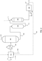
- FIG. 1 An oxidative desulfurization system that can be used in one embodiment of the invention is shown in FIG. 1 .
- This system generally includes a mixing zone 10, a heating zone 20, a flashing zone 30, an oxidation reaction 50 and an oxidation by-product separation zone 60.
- a feedstock 1 containing undesirable hetero-aromatic sulfides such as benzothiophene and dibenzothiophene and a gaseous oxidant stream 2 are intimately mixed in a mixing zone 10 so as to dissolve at least a portion of the gaseous oxidant in the feedstock, of which a substantial portion is in liquid phase.
- the mixture is heated in heating zone 20, e.g., one or more furnaces, to the reaction temperature, and the heated mixture is passed to the flashing zone 30, e.g., one or more flash drum vessels.
- the feedstock and gaseous oxidant can also be separately heated (not shown), in conjunction with heating zone 20 or as a substitute thereto, e.g., in one or more feed/effluent heat exchangers, for instance, to recover heat from the effluent of the oxidation reaction zone.
- the oxidant-enhanced feedstream 4 containing saturated gaseous oxidant is transferred from the flashing zone 30 as a bottoms stream and is passed to the oxidation reaction zone 50.
- Excess gas 3 which can include excess oxidant gas and light components of the feedstock, is flashed off in flashing zone 30. All or a portion of stream 3 can optionally (as denoted by dashed lines in FIG. 1 ) be recycled to mixing zone 10 for mixing with the feedstock.
- Reactor effluents 5, oxidized products, from oxidation reaction zone 50 are passed to the separation zone 60 to separate an oxidation by-product stream 6 containing sulfoxides and/or sulfones and to recover a desulfurized hydrocarbon stream 7.
- the separation zone 60 to separate an oxidation by-product stream 6 containing sulfoxides and/or sulfones and to recover a desulfurized hydrocarbon stream 7.
- additional feedstock 11 can be introduced to the oxidative reaction zone 50.
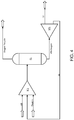
- FIG. 2 An oxidative desulfurization system that can be used in another embodiment of the invention is shown in FIG. 2 .
- This system generally includes a mixing zone 110, a heating zone 120, a flashing zone 130, an in-situ peroxide generation zone 140, an oxidation reaction zone 150 and an oxidation by-product separation zone 160.
- a feedstock 101 containing undesirable hetero-aromatic sulfides such as benzothiophenes and dibenzothiophenes, a stream 112 containing peroxide precursor compounds and a gaseous oxidant stream 102 are intimately mixed in a mixing zone 110 so as to dissolve at least a portion of the gaseous oxidant in the feedstock and peroxide precursor, of which a substantial portion is in liquid phase.
- the mixture is heated in heating zone 120, e.g., one or more furnaces, to the reaction temperature, and the heated mixture is passed to the flashing zone 130.
- the feedstock stream 102, the stream 112 containing peroxide precursor compounds and the gaseous oxidant 102 can also be separately heated (not shown), in conjunction with heating zone 120 or as a substitute thereto, e.g., in one or more feed/effluent heat exchangers, for instance, to recover heat from the effluent of the oxidation reaction zone.
- the oxidant-enhanced feedstream 104 containing saturated gaseous oxidant and peroxide precursors is transferred from the flashing zone 130 as a bottoms stream and is passed to the in-situ peroxide generation zone 140.
- Excess gas 103 which can include excess oxidant gas and light components of the feedstock, is flashed off in flashing zone 130. All or a portion of stream 103 can optionally (as denoted by dashed lines in FIG. 2 ) be recycled to mixing zone 110 for mixing with the feedstock and peroxide precursor.
- An effluents stream 114 containing peroxides generated in-situ within zone 140 is passed to oxidation reaction zone 150.
- Reactor effluents 105, oxidized products, from oxidation reaction zone 150 are passed to the separation zone 160 to separate an oxidation by-product stream 106 containing sulfoxides and/or sulfones and to recover a desulfurized hydrocarbon stream 107.
- a portion 109 of the desulfurized hydrocarbon effluent 107 is recycled back to the reactor as a diluent stream.
- additional feedstock 111 can be introduced to the oxidative reaction zone 150.
- the in-situ generated organic peroxides are of the general formula R'-OO-R, wherein R represents an organic group containing one aromatic, multi-ring aromatics or naphtheno-aromatics substituted with one or several alkyl groups that have exposed tertiary hydrogen readily susceptible to oxidation, and R' is preferably hydrogen.
- the mixing zone upstream of the reactor in the systems of FIGs. 1 and 2 receives gaseous oxidant, fresh feedstock and, optionally, recycled product that has passed through a reactor.
- the feed is saturated with gaseous oxidant under predetermined conditions of pressure, temperature and molar ratio to dissolve at least a substantial portion of the requisite gaseous oxidant into the feedstock to produce a combined feed/dissolved gaseous oxidant stream as the reactor influent.
- residence time of gas and liquid components downstream of the mixing zone including piping, heater and flash vessel, can promote further interaction between the gas a liquid to dissolve gas in liquid feedstock.
- Gas phase oxidant is minimized and eliminated by dissolving at least a substantial portion of the requisite gaseous oxidant in the hydrocarbon feedstock, and flashing the feedstock under predetermined conditions upstream of the reactor to produce a substantially single phase of liquid hydrocarbon feedstock containing dissolved gaseous oxidant as influent to the reactor.
- the gaseous oxidant is at or above the saturation level at the selected temperature and pressure.
- the specified elevated pressure conditions can be maintained throughout the series of unit operations from the mixing zone through the reaction zone to dissolve and maintain the gas saturated in liquid phase. Flashed gases from the flashing zone can be maintained under the requisite pressure or compressed prior to recycle to the mixing zone. Recycled hydrocarbons (streams 9, 109 ) and additional hydrocarbon feeds (streams 11, 111 ) also can be introduced to the mixing zone at the operating pressure of the mixing zone.
- the gaseous oxidant can comprise molecular oxygen O 2 , mixtures containing O 2 such as air, or other gaseous sources of oxygen suitable as reactant in oxidative desulfurization reactions.
- oxygen depleted air can be used as the gaseous oxidant, i.e., the concentration of oxygen can be less than about 21 vol. %.
- the oxygen-containing stream generally has an oxygen content of at least 0.01 vol. %.
- the gases can be supplied from air and optionally in combination with inert diluents such as nitrogen. Other gaseous oxidants can also be used such as oxides of nitrogen.
- the mixing zone in the herein processes can be a suitable apparatus that achieves the necessary intimate mixing of the substantially liquid feedstock and gas so that sufficient gaseous oxidant is dissolved in the hydrocarbon feedstock.
- the mixing zone can include a combined inlet for the gaseous oxidant and the feedstock.
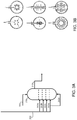
- Effective unit operations include one or more gas-liquid distributor vessels, which apparatuses can include spargers, injection nozzles, or other devices that impart sufficient velocity to inject the gaseous oxidant into the liquid hydrocarbon with turbulent mixing and thereby promote gas saturation into the feed. Suitable apparatus are described with respect to FIGs. 3A and 3B herein.
- a column is used as a gas distributor vessel 270, in which gaseous oxidant 202 is injected at plural locations 202a, 202b, 202c, 202d and 202e.
- Gaseous oxidant is injected thru distributors into the column for adequate mixing to effectively dissolve gaseous oxidant in the feedstock.
- suitable injection nozzles can be provided proximate several plates (locations 202a-202d ) and also at the bottom of the column (location 202e ).
- the feedstock 201 (or combination of feedstock and peroxide precursor, as in the embodiment of FIG. 2 ) can be fed from the bottom or top of the column.
- the effluent 272 is the oxidant-enhanced feedstock (or combination of feedstock and peroxide precursor as in the embodiment of FIG. 2 ).
- gas distributors can include tubular injectors fitted with nozzles and/or jets that are configured to uniformly distribute gaseous oxidant into the flowing hydrocarbon feedstock in a column or vessel in order to achieve a saturation state in the mixing zone.
- the hydrocarbon stream that is subjected to oxidative desulfurization can be derived from naturally occurring fossil fuels such as crude oil, bitumens, biofuel, shale oils, coal liquids, intermediate refinery products or their distillation fractions such as naphtha, gas oil, vacuum gas oil or vacuum residue or combination thereof.
- a suitable feedstock can be any hydrocarbon mixture having boiling points ranging from about 36°C to about 2000°C, although one of ordinary skill in the art will appreciated that certain other hydrocarbon streams can benefit from the practice of the system and method of the present invention.
- a functionally effective amount of gaseous oxidant can be dissolved in the hydrocarbon feedstock (or combination of feedstock and peroxide precursor, as in the embodiment of FIG. 2 ).
- the amount of gaseous oxidant dissolved in the feedstock depends on various factors, including the operating conditions of the mixing zone and the flashing zone, and the boiling point of the feed.
- the operating conditions for the mixing zone in processes described herein includes a pressure in the range of from about 1-100 bar, in certain embodiments from about 1-50 bar, and in further embodiments from about 1-30 bar; a temperature in the range of from about 20°C - 400°C, in certain embodiments from about 20°C - 300°C, and in further embodiments from about 20°C - 200°C; a residence time of from about 0.1 - 30 minutes, in certain embodiments from about 0.1 - 15 minutes, and in further embodiments from about 0.1 - 5 minutes; and an oxidant (O 2 ) to sulfur molar ratio of from about 1:1 - 100:1, in certain embodiments from about 1:1 - 30:1, and in further embodiments from about 1:1 - 5:1.
- the oxidative desulfurization reaction zone can be a suitable liquid-solid reaction zone known to those skilled in the art.
- the reaction zone can include one or more reactors, such as fixed-bed reactors, ebullated bed reactors, slurry bed reactors, moving bed reactors, continuous stirred tank reactor, and/or tubular reactors.
- a fixed bed reactor can also comprise a plurality of catalyst beds.
- the oxidation catalyst can be selected from one or more heterogeneous catalysts having metals from Group VB to Group VIIIB of the Periodic Table, including those selected from of Mn, Co, Fe, Cr and Mo.
- Suitable catalyst materials comprise at least one oxide of general formula M x O y as defined above, and element M is preferably selected from the group that consists of titanium, zirconium, vanadium, chromium, molybdenum and tungsten. Molybdenum oxide MoO 3 , vanadium oxide V 2 O 5 and zirconium oxide ZrO 2 , taken either separately or in a mixture, can be useful.
- the catalyst material can be provided in the form of powder, balls or extrudates.
- Certain embodiments described herein for instance using a heterogeneous catalyst system enable a range of applications for the present process.
- the herein described process can be carried out on skid mounted units, e.g., at terminals, pipelines, garages, forecourts, or on board fuel cell containing vehicles where sulfur sensitive hydrocarbon reformers and fuel cells are employed.
- the catalyst can be a suitable homogeneous oxidative desulfurization catalyst, which is mixed with the feedstock, such as oxides and/or organo metal complexes of copper, zinc, cerium, cobalt, tungsten, nickel, vanadium, molybdenum, platinum, palladium, iron and mixtures thereof.
- suitable homogeneous oxidative desulfurization catalyst such as oxides and/or organo metal complexes of copper, zinc, cerium, cobalt, tungsten, nickel, vanadium, molybdenum, platinum, palladium, iron and mixtures thereof.
- the operating conditions in the oxidation reaction zone in the processes described herein includes a pressure in the range of from about 1-100 bar, in certain embodiments from about 1-50 bar, and in further embodiments from about 1-30 bar; a temperature in the range of from about 20°C - 400°C, in certain embodiments from about 20°C - 300°C, and in further embodiments from about 20°C - 200°C; a residence time of from about 5 - 180 minutes, in certain embodiments from about 15 - 90 minutes, and in further embodiments from about 15 - 30 minutes; and an oxidant (O 2 ) to sulfur molar ratio of from about 1:1 - 100:1, in certain embodiments from about 1:1 - 30:1, and in further embodiments from about 1:1 - 5:1.
- Operating conditions for the flash vessel in processes described herein includes a pressure in the range of from about 1-100 bar, in certain embodiments from about 1-50 bar, and in further embodiments from about 1-30 bar; a temperature in the range of from about 20°C - 400°C, in certain embodiments from about 20°C - 150°C, and in further embodiments from about 20°C - 200°C; a residence time of from about 5 - 180 minutes, in certain embodiments from about 15 - 90 minutes, and in further embodiments from about 30 - 30 minutes; and an oxidant to sulfur molar ratio of from about 1:1 - 100:1, in certain embodiments from about 1:1 - 30:1, and in further embodiments from about 1:1 - 5:1.
- Operating conditions for the in-situ peroxide generation vessel in the process described herein with respect to FIG. 2 includes a pressure in the range of from about 1-100 bar, in certain embodiments from about 1-50 bar, and in further embodiments from about 1-30 bar; a temperature in the range of from about 20°C - 300°C, in certain embodiments from about 20°C - 150°C, and in further embodiments from about 35°C - 60°C; a residence time of from about 5 - 180 minutes, in certain embodiments from about 15 - 90 minutes, and in further embodiments from about 30 - 60 minutes; and an oxidant to sulfur molar ratio of from about 1:1 - 100:1, in certain embodiments from about 1:1 - 30:1, and in further embodiments from about 1:1 - 4:1.
- the product separation zone for removal of sulfoxides and sulfones can be a suitable unit operation or series of unit operations known for this purpose, e.g., one or more extraction and/or adsorption unit operations.
- oxygen and liquid hydrocarbons are contacted in a vessel at relatively high pressure and then the gases are flashed off in a flash drum, whereby the oxygen containing liquid is sent to a suitable reactor for oxidative desulfurization, with an important aspect being the elimination or minimization of the gas phase.
- a substantially two-phase system is provided, which comprises a solid catalyst phase and a liquid phase in the form of the hydrocarbon and the dissolved oxygen in liquid.
- Gas solubility is a function of hydrocarbon type, pressure and temperature. Hydrocarbons have certain capacity to absorb or dissolve the gaseous oxidant. To increase the concentration of the dissolved gaseous oxidant, the oxidation reactor effluents or desulfurized hydrocarbons after the separation steps can be recycled back to the reactor as a diluent.
- gaseous oxygen oxygen, air, oxides of nitrogen
- the oil /oxygen solution and in certain embodiments, diluents, e.g., in the form of desulfurized hydrocarbons from the product separation zone_ can then be fed to a suitable reactor within which the oil and oxygen react. No additional oxidant in gas phase is required and accordingly oxygen recirculation is avoided.
- conventionally large reactors can be replaced by much smaller or simpler reactors.
- gas phase oxygen recycle compressors can be avoided.
- Oxygen in Hydrocarbon Solution Oxygen solubility of a diesel oil with density of 0.8346 Kg/lt and sulfur content of 500 ppmw was calculated using PROII simulation software licensed by Invensys System Inc. A flow diagram is shown in FIG. 4 .
- the distillation data for the diesel oil is given in Table 3.
- Table 3 ASTM D86 Distillation W% Off Temperature, °C IBP 182 5% 198 10% 209 30% 236 50% 265 70% 295 90% 333 95% 341 EBP 352
- Table 4 shows the solubility of oxygen (mol%) in diesel oil as a function of temperature and pressure: Table 4 - Solubility of Oxygen in Diesel Oil Mol% of oxygen in Diesel oil Temperature Pressure, bar 100 °C 200 °C 300 °C 350 °C 1 0.002 0.002 NA NA 10 0.017 0.018 NA NA 20 0.034 0.037 0.043 NA 30 0.050 0.055 0.065 NA 40 0.066 0.072 0.087 0.097 50 0.081 0.090 0.108 0.122 80 0.124 0.138 0.169 0.192 100 0.150 0.168 0.207 0.236 150 0.210 0.238 0.292 0.334 200 0.263 0.298 0.366 0.418 NA-all in vapor phase.
- Table 5 shows molar fractions and rate of different streams in the exemplary process.
Landscapes
- Chemical & Material Sciences (AREA)
- Oil, Petroleum & Natural Gas (AREA)
- Engineering & Computer Science (AREA)
- Chemical Kinetics & Catalysis (AREA)
- General Chemical & Material Sciences (AREA)
- Organic Chemistry (AREA)
- Production Of Liquid Hydrocarbon Mixture For Refining Petroleum (AREA)
- Hydrogen, Water And Hydrids (AREA)
Applications Claiming Priority (2)
| Application Number | Priority Date | Filing Date | Title |
|---|---|---|---|
| US201261724672P | 2012-11-09 | 2012-11-09 | |
| PCT/US2013/069353 WO2014074958A1 (en) | 2012-11-09 | 2013-11-09 | Oxidative desulfurization process and system using gaseous oxidant-enhanced feed |
Publications (2)
| Publication Number | Publication Date |
|---|---|
| EP2917307A1 EP2917307A1 (en) | 2015-09-16 |
| EP2917307B1 true EP2917307B1 (en) | 2019-01-09 |
Family
ID=49681138
Family Applications (1)
| Application Number | Title | Priority Date | Filing Date |
|---|---|---|---|
| EP13798797.0A Not-in-force EP2917307B1 (en) | 2012-11-09 | 2013-11-09 | Oxidative desulfurization process |
Country Status (8)
| Country | Link |
|---|---|
| US (1) | US9719029B2 (enExample) |
| EP (1) | EP2917307B1 (enExample) |
| JP (1) | JP6144352B2 (enExample) |
| KR (1) | KR102187212B1 (enExample) |
| CN (1) | CN104919025B (enExample) |
| SA (1) | SA515360389B1 (enExample) |
| SG (1) | SG11201503610PA (enExample) |
| WO (1) | WO2014074958A1 (enExample) |
Families Citing this family (9)
| Publication number | Priority date | Publication date | Assignee | Title |
|---|---|---|---|---|
| EP3551731A1 (en) * | 2017-01-25 | 2019-10-16 | Saudi Arabian Oil Company | Oxidative desulfurization of oil fractions and sulfone management using an fcc |
| KR20190116466A (ko) * | 2017-02-20 | 2019-10-14 | 사우디 아라비안 오일 컴퍼니 | 오일 분획의 산화적 탈황 및 fcc를 사용한 술폰 관리 |
| JP2020509113A (ja) * | 2017-02-20 | 2020-03-26 | サウジ アラビアン オイル カンパニー | コーカーを用いた脱硫及びスルホン除去 |
| JP2020511580A (ja) * | 2017-03-21 | 2020-04-16 | サウジ アラビアン オイル カンパニー | 溶剤脱れきを使用した酸化脱硫およびスルホン廃棄の処理 |
| CN108003920B (zh) * | 2017-07-18 | 2020-12-04 | 华南理工大学 | 一种用负载型金属氧化物双功能催化吸附脱硫剂的燃料氧化脱硫方法 |
| CN107803192A (zh) * | 2017-07-18 | 2018-03-16 | 华南理工大学 | 一种燃料氧化脱硫双功能催化吸附剂清洁再生工艺 |
| US10703998B2 (en) * | 2018-10-22 | 2020-07-07 | Saudi Arabian Oil Company | Catalytic demetallization and gas phase oxidative desulfurization of residual oil |
| US11292970B2 (en) * | 2019-11-05 | 2022-04-05 | Saudi Arabian Oil Company | Hydrocracking process and system including separation of heavy poly nuclear aromatics from recycle by oxidation |
| US11965135B1 (en) | 2023-04-12 | 2024-04-23 | Saudi Arabian Oil Company | Methods for reactivity based hydroprocessing |
Family Cites Families (29)
| Publication number | Priority date | Publication date | Assignee | Title |
|---|---|---|---|---|
| US2504429A (en) | 1946-04-18 | 1950-04-18 | Phillips Petroleum Co | Recovery of hydrocarbons from natural gas |
| US2749284A (en) | 1950-11-15 | 1956-06-05 | British Petroleum Co | Treatment of sulphur-containing mineral oils with kerosene peroxides |
| BE548193A (enExample) * | 1953-03-12 | |||
| BE583880A (enExample) * | 1958-10-24 | |||
| BE625074A (enExample) | 1961-11-24 | |||
| US3767563A (en) | 1971-12-23 | 1973-10-23 | Texaco Inc | Adsorption-desorption process for removing an unwanted component from a reaction charge mixture |
| US3847800A (en) * | 1973-08-06 | 1974-11-12 | Kvb Eng Inc | Method for removing sulfur and nitrogen in petroleum oils |
| US3919402A (en) * | 1973-08-06 | 1975-11-11 | Kvb Inc | Petroleum oil desulfurization process |
| US4830733A (en) | 1987-10-05 | 1989-05-16 | Uop | Integrated process for the removal of sulfur compounds from fluid streams |
| US4875997A (en) * | 1988-11-17 | 1989-10-24 | Montana Refining Company | Process for treating hydrocarbons containing mercaptans |
| US5753102A (en) | 1994-11-11 | 1998-05-19 | Izumi Funakoshi | Process for recovering organic sulfur compounds from fuel oil |
| US5730860A (en) | 1995-08-14 | 1998-03-24 | The Pritchard Corporation | Process for desulfurizing gasoline and hydrocarbon feedstocks |
| US5910440A (en) | 1996-04-12 | 1999-06-08 | Exxon Research And Engineering Company | Method for the removal of organic sulfur from carbonaceous materials |
| US5824207A (en) | 1996-04-30 | 1998-10-20 | Novetek Octane Enhancement, Ltd. | Method and apparatus for oxidizing an organic liquid |
| FR2764610B1 (fr) | 1997-06-12 | 1999-09-17 | Centre Nat Rech Scient | Procede de separation de composes benzothiopheniques d'un melange d'hydrocarbures les contenant, et melange d'hydrocarbures obtenu par ce procede |
| US7291257B2 (en) | 1997-06-24 | 2007-11-06 | Process Dynamics, Inc. | Two phase hydroprocessing |
| US6087544A (en) | 1998-05-07 | 2000-07-11 | Exxon Research And Engineering Co. | Process for the production of high lubricity low sulfur distillate fuels |
| WO2000000430A2 (en) * | 1998-06-29 | 2000-01-06 | California Institute Of Technology | Molecular sieve cit-6 |
| US6277271B1 (en) | 1998-07-15 | 2001-08-21 | Uop Llc | Process for the desulfurization of a hydrocarbonaceoous oil |
| US6171478B1 (en) | 1998-07-15 | 2001-01-09 | Uop Llc | Process for the desulfurization of a hydrocarbonaceous oil |
| US6402940B1 (en) | 2000-09-01 | 2002-06-11 | Unipure Corporation | Process for removing low amounts of organic sulfur from hydrocarbon fuels |
| US20030094400A1 (en) | 2001-08-10 | 2003-05-22 | Levy Robert Edward | Hydrodesulfurization of oxidized sulfur compounds in liquid hydrocarbons |
| US7279253B2 (en) * | 2003-09-12 | 2007-10-09 | Canon Kabushiki Kaisha | Near-field light generating structure, near-field exposure mask, and near-field generating method |
| US7276152B2 (en) * | 2004-11-23 | 2007-10-02 | Cpc Corporation, Taiwan | Oxidative desulfurization and denitrogenation of petroleum oils |
| EP1841838A1 (en) | 2004-12-29 | 2007-10-10 | BP Corporation North America Inc. | Oxidative desulfurization process |
| US7297253B1 (en) * | 2005-07-19 | 2007-11-20 | Uop Llc | Process for producing hydroperoxides |
| US7731837B2 (en) * | 2006-09-08 | 2010-06-08 | The Penn State Research Foundation | Oxidatively regenerable adsorbents for sulfur removal |
| US8658027B2 (en) | 2010-03-29 | 2014-02-25 | Saudi Arabian Oil Company | Integrated hydrotreating and oxidative desulfurization process |
| WO2012082851A1 (en) * | 2010-12-15 | 2012-06-21 | Saudi Arabian Oil Company | Desulfurization of hydrocarbon feed using gaseous oxidant |
-
2013
- 2013-11-09 CN CN201380066824.2A patent/CN104919025B/zh not_active Expired - Fee Related
- 2013-11-09 EP EP13798797.0A patent/EP2917307B1/en not_active Not-in-force
- 2013-11-09 JP JP2015541969A patent/JP6144352B2/ja not_active Expired - Fee Related
- 2013-11-09 WO PCT/US2013/069353 patent/WO2014074958A1/en not_active Ceased
- 2013-11-09 SG SG11201503610PA patent/SG11201503610PA/en unknown
- 2013-11-09 KR KR1020157015212A patent/KR102187212B1/ko not_active Expired - Fee Related
- 2013-11-11 US US14/076,329 patent/US9719029B2/en active Active
-
2015
- 2015-05-05 SA SA515360389A patent/SA515360389B1/ar unknown
Non-Patent Citations (1)
| Title |
|---|
| None * |
Also Published As
| Publication number | Publication date |
|---|---|
| KR102187212B1 (ko) | 2020-12-04 |
| CN104919025B (zh) | 2017-07-28 |
| US20140131255A1 (en) | 2014-05-15 |
| SA515360389B1 (ar) | 2018-03-18 |
| JP6144352B2 (ja) | 2017-06-07 |
| SG11201503610PA (en) | 2015-06-29 |
| CN104919025A (zh) | 2015-09-16 |
| US9719029B2 (en) | 2017-08-01 |
| WO2014074958A1 (en) | 2014-05-15 |
| KR20150105946A (ko) | 2015-09-18 |
| EP2917307A1 (en) | 2015-09-16 |
| JP2015533927A (ja) | 2015-11-26 |
Similar Documents
| Publication | Publication Date | Title |
|---|---|---|
| EP2917307B1 (en) | Oxidative desulfurization process | |
| US9464241B2 (en) | Hydrotreating unit with integrated oxidative desulfurization | |
| EP2651860B1 (en) | Desulfurization of hydrocarbon feed using gaseous oxidant | |
| CN103781882B (zh) | 用于原位有机过氧化物生产和氧化性杂原子转化的集成系统和方法 | |
| US10369546B2 (en) | Process for oxidative desulfurization with integrated sulfone decomposition | |
| CN103827264B (zh) | 流化催化裂化工艺中的氧化脱硫 | |
| US9296960B2 (en) | Targeted desulfurization process and apparatus integrating oxidative desulfurization and hydrodesulfurization to produce diesel fuel having an ultra-low level of organosulfur compounds | |
| WO2012050692A1 (en) | Integrated deasphalting and oxidative removal of heteroatom hydrocarbon compounds from liquid hydrocarbon feedstocks | |
| US20110220550A1 (en) | Mild hydrodesulfurization integrating targeted oxidative desulfurization to produce diesel fuel having an ultra-low level of organosulfur compounds | |
| SA515360202B1 (ar) | عملية لتقليل محتوى الكبريت من هيدروكربونات تتضمن كبريت مؤكسد | |
| Isufaj | Extending Catalytic Oxidative Desulfurization to All Types of Fuels Via Oxidative Desulfurization-Steam Assisted (ODESSA) Process | |
| EP3870677A1 (en) | Integrated process for solvent deasphalting and gas phase oxidative desulfurization of residual oil |
Legal Events
| Date | Code | Title | Description |
|---|---|---|---|
| PUAI | Public reference made under article 153(3) epc to a published international application that has entered the european phase |
Free format text: ORIGINAL CODE: 0009012 |
|
| 17P | Request for examination filed |
Effective date: 20150605 |
|
| AK | Designated contracting states |
Kind code of ref document: A1 Designated state(s): AL AT BE BG CH CY CZ DE DK EE ES FI FR GB GR HR HU IE IS IT LI LT LU LV MC MK MT NL NO PL PT RO RS SE SI SK SM TR |
|
| AX | Request for extension of the european patent |
Extension state: BA ME |
|
| RIN1 | Information on inventor provided before grant (corrected) |
Inventor name: KOSEOGLU, OMER, REFA Inventor name: BOURANE, ABDENNOUR |
|
| DAX | Request for extension of the european patent (deleted) | ||
| STAA | Information on the status of an ep patent application or granted ep patent |
Free format text: STATUS: EXAMINATION IS IN PROGRESS |
|
| 17Q | First examination report despatched |
Effective date: 20171207 |
|
| GRAP | Despatch of communication of intention to grant a patent |
Free format text: ORIGINAL CODE: EPIDOSNIGR1 |
|
| STAA | Information on the status of an ep patent application or granted ep patent |
Free format text: STATUS: GRANT OF PATENT IS INTENDED |
|
| INTG | Intention to grant announced |
Effective date: 20180831 |
|
| GRAS | Grant fee paid |
Free format text: ORIGINAL CODE: EPIDOSNIGR3 |
|
| GRAA | (expected) grant |
Free format text: ORIGINAL CODE: 0009210 |
|
| STAA | Information on the status of an ep patent application or granted ep patent |
Free format text: STATUS: THE PATENT HAS BEEN GRANTED |
|
| AK | Designated contracting states |
Kind code of ref document: B1 Designated state(s): AL AT BE BG CH CY CZ DE DK EE ES FI FR GB GR HR HU IE IS IT LI LT LU LV MC MK MT NL NO PL PT RO RS SE SI SK SM TR |
|
| REG | Reference to a national code |
Ref country code: GB Ref legal event code: FG4D |
|
| REG | Reference to a national code |
Ref country code: CH Ref legal event code: EP Ref country code: AT Ref legal event code: REF Ref document number: 1087271 Country of ref document: AT Kind code of ref document: T Effective date: 20190115 |
|
| REG | Reference to a national code |
Ref country code: DE Ref legal event code: R096 Ref document number: 602013049631 Country of ref document: DE |
|
| REG | Reference to a national code |
Ref country code: IE Ref legal event code: FG4D |
|
| REG | Reference to a national code |
Ref country code: NL Ref legal event code: FP |
|
| REG | Reference to a national code |
Ref country code: LT Ref legal event code: MG4D |
|
| REG | Reference to a national code |
Ref country code: NO Ref legal event code: T2 Effective date: 20190109 |
|
| REG | Reference to a national code |
Ref country code: AT Ref legal event code: MK05 Ref document number: 1087271 Country of ref document: AT Kind code of ref document: T Effective date: 20190109 |
|
| PG25 | Lapsed in a contracting state [announced via postgrant information from national office to epo] |
Ref country code: ES Free format text: LAPSE BECAUSE OF FAILURE TO SUBMIT A TRANSLATION OF THE DESCRIPTION OR TO PAY THE FEE WITHIN THE PRESCRIBED TIME-LIMIT Effective date: 20190109 Ref country code: SE Free format text: LAPSE BECAUSE OF FAILURE TO SUBMIT A TRANSLATION OF THE DESCRIPTION OR TO PAY THE FEE WITHIN THE PRESCRIBED TIME-LIMIT Effective date: 20190109 Ref country code: PT Free format text: LAPSE BECAUSE OF FAILURE TO SUBMIT A TRANSLATION OF THE DESCRIPTION OR TO PAY THE FEE WITHIN THE PRESCRIBED TIME-LIMIT Effective date: 20190509 Ref country code: LT Free format text: LAPSE BECAUSE OF FAILURE TO SUBMIT A TRANSLATION OF THE DESCRIPTION OR TO PAY THE FEE WITHIN THE PRESCRIBED TIME-LIMIT Effective date: 20190109 Ref country code: PL Free format text: LAPSE BECAUSE OF FAILURE TO SUBMIT A TRANSLATION OF THE DESCRIPTION OR TO PAY THE FEE WITHIN THE PRESCRIBED TIME-LIMIT Effective date: 20190109 Ref country code: FI Free format text: LAPSE BECAUSE OF FAILURE TO SUBMIT A TRANSLATION OF THE DESCRIPTION OR TO PAY THE FEE WITHIN THE PRESCRIBED TIME-LIMIT Effective date: 20190109 |
|
| PG25 | Lapsed in a contracting state [announced via postgrant information from national office to epo] |
Ref country code: BG Free format text: LAPSE BECAUSE OF FAILURE TO SUBMIT A TRANSLATION OF THE DESCRIPTION OR TO PAY THE FEE WITHIN THE PRESCRIBED TIME-LIMIT Effective date: 20190409 Ref country code: IS Free format text: LAPSE BECAUSE OF FAILURE TO SUBMIT A TRANSLATION OF THE DESCRIPTION OR TO PAY THE FEE WITHIN THE PRESCRIBED TIME-LIMIT Effective date: 20190509 Ref country code: RS Free format text: LAPSE BECAUSE OF FAILURE TO SUBMIT A TRANSLATION OF THE DESCRIPTION OR TO PAY THE FEE WITHIN THE PRESCRIBED TIME-LIMIT Effective date: 20190109 Ref country code: GR Free format text: LAPSE BECAUSE OF FAILURE TO SUBMIT A TRANSLATION OF THE DESCRIPTION OR TO PAY THE FEE WITHIN THE PRESCRIBED TIME-LIMIT Effective date: 20190410 Ref country code: LV Free format text: LAPSE BECAUSE OF FAILURE TO SUBMIT A TRANSLATION OF THE DESCRIPTION OR TO PAY THE FEE WITHIN THE PRESCRIBED TIME-LIMIT Effective date: 20190109 Ref country code: HR Free format text: LAPSE BECAUSE OF FAILURE TO SUBMIT A TRANSLATION OF THE DESCRIPTION OR TO PAY THE FEE WITHIN THE PRESCRIBED TIME-LIMIT Effective date: 20190109 |
|
| REG | Reference to a national code |
Ref country code: DE Ref legal event code: R097 Ref document number: 602013049631 Country of ref document: DE |
|
| PG25 | Lapsed in a contracting state [announced via postgrant information from national office to epo] |
Ref country code: RO Free format text: LAPSE BECAUSE OF FAILURE TO SUBMIT A TRANSLATION OF THE DESCRIPTION OR TO PAY THE FEE WITHIN THE PRESCRIBED TIME-LIMIT Effective date: 20190109 Ref country code: CZ Free format text: LAPSE BECAUSE OF FAILURE TO SUBMIT A TRANSLATION OF THE DESCRIPTION OR TO PAY THE FEE WITHIN THE PRESCRIBED TIME-LIMIT Effective date: 20190109 Ref country code: AL Free format text: LAPSE BECAUSE OF FAILURE TO SUBMIT A TRANSLATION OF THE DESCRIPTION OR TO PAY THE FEE WITHIN THE PRESCRIBED TIME-LIMIT Effective date: 20190109 Ref country code: SK Free format text: LAPSE BECAUSE OF FAILURE TO SUBMIT A TRANSLATION OF THE DESCRIPTION OR TO PAY THE FEE WITHIN THE PRESCRIBED TIME-LIMIT Effective date: 20190109 Ref country code: AT Free format text: LAPSE BECAUSE OF FAILURE TO SUBMIT A TRANSLATION OF THE DESCRIPTION OR TO PAY THE FEE WITHIN THE PRESCRIBED TIME-LIMIT Effective date: 20190109 Ref country code: DK Free format text: LAPSE BECAUSE OF FAILURE TO SUBMIT A TRANSLATION OF THE DESCRIPTION OR TO PAY THE FEE WITHIN THE PRESCRIBED TIME-LIMIT Effective date: 20190109 Ref country code: EE Free format text: LAPSE BECAUSE OF FAILURE TO SUBMIT A TRANSLATION OF THE DESCRIPTION OR TO PAY THE FEE WITHIN THE PRESCRIBED TIME-LIMIT Effective date: 20190109 |
|
| PLBE | No opposition filed within time limit |
Free format text: ORIGINAL CODE: 0009261 |
|
| STAA | Information on the status of an ep patent application or granted ep patent |
Free format text: STATUS: NO OPPOSITION FILED WITHIN TIME LIMIT |
|
| PG25 | Lapsed in a contracting state [announced via postgrant information from national office to epo] |
Ref country code: SM Free format text: LAPSE BECAUSE OF FAILURE TO SUBMIT A TRANSLATION OF THE DESCRIPTION OR TO PAY THE FEE WITHIN THE PRESCRIBED TIME-LIMIT Effective date: 20190109 |
|
| 26N | No opposition filed |
Effective date: 20191010 |
|
| PG25 | Lapsed in a contracting state [announced via postgrant information from national office to epo] |
Ref country code: SI Free format text: LAPSE BECAUSE OF FAILURE TO SUBMIT A TRANSLATION OF THE DESCRIPTION OR TO PAY THE FEE WITHIN THE PRESCRIBED TIME-LIMIT Effective date: 20190109 |
|
| PG25 | Lapsed in a contracting state [announced via postgrant information from national office to epo] |
Ref country code: TR Free format text: LAPSE BECAUSE OF FAILURE TO SUBMIT A TRANSLATION OF THE DESCRIPTION OR TO PAY THE FEE WITHIN THE PRESCRIBED TIME-LIMIT Effective date: 20190109 |
|
| REG | Reference to a national code |
Ref country code: CH Ref legal event code: PL |
|
| PG25 | Lapsed in a contracting state [announced via postgrant information from national office to epo] |
Ref country code: MC Free format text: LAPSE BECAUSE OF FAILURE TO SUBMIT A TRANSLATION OF THE DESCRIPTION OR TO PAY THE FEE WITHIN THE PRESCRIBED TIME-LIMIT Effective date: 20190109 Ref country code: CH Free format text: LAPSE BECAUSE OF NON-PAYMENT OF DUE FEES Effective date: 20191130 Ref country code: LI Free format text: LAPSE BECAUSE OF NON-PAYMENT OF DUE FEES Effective date: 20191130 Ref country code: LU Free format text: LAPSE BECAUSE OF NON-PAYMENT OF DUE FEES Effective date: 20191109 |
|
| PGFP | Annual fee paid to national office [announced via postgrant information from national office to epo] |
Ref country code: FR Payment date: 20200427 Year of fee payment: 7 Ref country code: NL Payment date: 20200426 Year of fee payment: 7 Ref country code: DE Payment date: 20200429 Year of fee payment: 7 Ref country code: NO Payment date: 20200429 Year of fee payment: 7 |
|
| REG | Reference to a national code |
Ref country code: BE Ref legal event code: MM Effective date: 20191130 |
|
| PGFP | Annual fee paid to national office [announced via postgrant information from national office to epo] |
Ref country code: GB Payment date: 20200427 Year of fee payment: 7 Ref country code: IT Payment date: 20200508 Year of fee payment: 7 |
|
| PG25 | Lapsed in a contracting state [announced via postgrant information from national office to epo] |
Ref country code: IE Free format text: LAPSE BECAUSE OF NON-PAYMENT OF DUE FEES Effective date: 20191109 |
|
| PG25 | Lapsed in a contracting state [announced via postgrant information from national office to epo] |
Ref country code: BE Free format text: LAPSE BECAUSE OF NON-PAYMENT OF DUE FEES Effective date: 20191130 |
|
| PG25 | Lapsed in a contracting state [announced via postgrant information from national office to epo] |
Ref country code: CY Free format text: LAPSE BECAUSE OF FAILURE TO SUBMIT A TRANSLATION OF THE DESCRIPTION OR TO PAY THE FEE WITHIN THE PRESCRIBED TIME-LIMIT Effective date: 20190109 |
|
| REG | Reference to a national code |
Ref country code: DE Ref legal event code: R119 Ref document number: 602013049631 Country of ref document: DE |
|
| REG | Reference to a national code |
Ref country code: NO Ref legal event code: MMEP |
|
| REG | Reference to a national code |
Ref country code: NL Ref legal event code: MM Effective date: 20201201 |
|
| GBPC | Gb: european patent ceased through non-payment of renewal fee |
Effective date: 20201109 |
|
| PG25 | Lapsed in a contracting state [announced via postgrant information from national office to epo] |
Ref country code: NO Free format text: LAPSE BECAUSE OF NON-PAYMENT OF DUE FEES Effective date: 20201130 Ref country code: MT Free format text: LAPSE BECAUSE OF FAILURE TO SUBMIT A TRANSLATION OF THE DESCRIPTION OR TO PAY THE FEE WITHIN THE PRESCRIBED TIME-LIMIT Effective date: 20190109 Ref country code: HU Free format text: LAPSE BECAUSE OF FAILURE TO SUBMIT A TRANSLATION OF THE DESCRIPTION OR TO PAY THE FEE WITHIN THE PRESCRIBED TIME-LIMIT; INVALID AB INITIO Effective date: 20131109 |
|
| PG25 | Lapsed in a contracting state [announced via postgrant information from national office to epo] |
Ref country code: NL Free format text: LAPSE BECAUSE OF NON-PAYMENT OF DUE FEES Effective date: 20201201 |
|
| PG25 | Lapsed in a contracting state [announced via postgrant information from national office to epo] |
Ref country code: IT Free format text: LAPSE BECAUSE OF NON-PAYMENT OF DUE FEES Effective date: 20201109 Ref country code: FR Free format text: LAPSE BECAUSE OF NON-PAYMENT OF DUE FEES Effective date: 20201130 |
|
| PG25 | Lapsed in a contracting state [announced via postgrant information from national office to epo] |
Ref country code: GB Free format text: LAPSE BECAUSE OF NON-PAYMENT OF DUE FEES Effective date: 20201109 Ref country code: DE Free format text: LAPSE BECAUSE OF NON-PAYMENT OF DUE FEES Effective date: 20210601 |
|
| PG25 | Lapsed in a contracting state [announced via postgrant information from national office to epo] |
Ref country code: MK Free format text: LAPSE BECAUSE OF FAILURE TO SUBMIT A TRANSLATION OF THE DESCRIPTION OR TO PAY THE FEE WITHIN THE PRESCRIBED TIME-LIMIT Effective date: 20190109 |