EP2916521B1 - Dispositif de communication, procédé de commande de sortie de données de transmission, et leur programme - Google Patents
Dispositif de communication, procédé de commande de sortie de données de transmission, et leur programme Download PDFInfo
- Publication number
- EP2916521B1 EP2916521B1 EP13850413.9A EP13850413A EP2916521B1 EP 2916521 B1 EP2916521 B1 EP 2916521B1 EP 13850413 A EP13850413 A EP 13850413A EP 2916521 B1 EP2916521 B1 EP 2916521B1
- Authority
- EP
- European Patent Office
- Prior art keywords
- transmission rate
- transmission
- rate control
- control mode
- unit
- Prior art date
- Legal status (The legal status is an assumption and is not a legal conclusion. Google has not performed a legal analysis and makes no representation as to the accuracy of the status listed.)
- Not-in-force
Links
Images


Classifications
-
- H—ELECTRICITY
- H04—ELECTRIC COMMUNICATION TECHNIQUE
- H04L—TRANSMISSION OF DIGITAL INFORMATION, e.g. TELEGRAPHIC COMMUNICATION
- H04L47/00—Traffic control in data switching networks
- H04L47/10—Flow control; Congestion control
- H04L47/32—Flow control; Congestion control by discarding or delaying data units, e.g. packets or frames
-
- H—ELECTRICITY
- H04—ELECTRIC COMMUNICATION TECHNIQUE
- H04L—TRANSMISSION OF DIGITAL INFORMATION, e.g. TELEGRAPHIC COMMUNICATION
- H04L47/00—Traffic control in data switching networks
- H04L47/10—Flow control; Congestion control
- H04L47/22—Traffic shaping
-
- H—ELECTRICITY
- H04—ELECTRIC COMMUNICATION TECHNIQUE
- H04L—TRANSMISSION OF DIGITAL INFORMATION, e.g. TELEGRAPHIC COMMUNICATION
- H04L47/00—Traffic control in data switching networks
- H04L47/10—Flow control; Congestion control
- H04L47/12—Avoiding congestion; Recovering from congestion
-
- H—ELECTRICITY
- H04—ELECTRIC COMMUNICATION TECHNIQUE
- H04L—TRANSMISSION OF DIGITAL INFORMATION, e.g. TELEGRAPHIC COMMUNICATION
- H04L47/00—Traffic control in data switching networks
- H04L47/10—Flow control; Congestion control
- H04L47/25—Flow control; Congestion control with rate being modified by the source upon detecting a change of network conditions
-
- H—ELECTRICITY
- H04—ELECTRIC COMMUNICATION TECHNIQUE
- H04L—TRANSMISSION OF DIGITAL INFORMATION, e.g. TELEGRAPHIC COMMUNICATION
- H04L69/00—Network arrangements, protocols or services independent of the application payload and not provided for in the other groups of this subclass
- H04L69/16—Implementation or adaptation of Internet protocol [IP], of transmission control protocol [TCP] or of user datagram protocol [UDP]
- H04L69/163—In-band adaptation of TCP data exchange; In-band control procedures
-
- H—ELECTRICITY
- H04—ELECTRIC COMMUNICATION TECHNIQUE
- H04L—TRANSMISSION OF DIGITAL INFORMATION, e.g. TELEGRAPHIC COMMUNICATION
- H04L47/00—Traffic control in data switching networks
- H04L47/10—Flow control; Congestion control
- H04L47/19—Flow control; Congestion control at layers above the network layer
- H04L47/193—Flow control; Congestion control at layers above the network layer at the transport layer, e.g. TCP related
-
- H—ELECTRICITY
- H04—ELECTRIC COMMUNICATION TECHNIQUE
- H04L—TRANSMISSION OF DIGITAL INFORMATION, e.g. TELEGRAPHIC COMMUNICATION
- H04L47/00—Traffic control in data switching networks
- H04L47/10—Flow control; Congestion control
- H04L47/27—Evaluation or update of window size, e.g. using information derived from acknowledged [ACK] packets
-
- H—ELECTRICITY
- H04—ELECTRIC COMMUNICATION TECHNIQUE
- H04L—TRANSMISSION OF DIGITAL INFORMATION, e.g. TELEGRAPHIC COMMUNICATION
- H04L47/00—Traffic control in data switching networks
- H04L47/10—Flow control; Congestion control
- H04L47/28—Flow control; Congestion control in relation to timing considerations
-
- H—ELECTRICITY
- H04—ELECTRIC COMMUNICATION TECHNIQUE
- H04W—WIRELESS COMMUNICATION NETWORKS
- H04W8/00—Network data management
- H04W8/02—Processing of mobility data, e.g. registration information at HLR [Home Location Register] or VLR [Visitor Location Register]; Transfer of mobility data, e.g. between HLR, VLR or external networks
- H04W8/04—Registration at HLR or HSS [Home Subscriber Server]
Definitions
- the present invention relates to a communication device or the like for performing a communication session via a network and, in particular, relates to a communication device, a transmission data output control method, and a program for same which use a communication protocol having a congestion control function such as TCP (Transmission Control Protocol).
- TCP Transmission Control Protocol
- TCP Transmission Control Protocol
- a data receive side notifies a receive buffer size (RWIN, Receive Window) to a data transmission side.
- the data transmission side may transmit an amount of data of the receive buffer size (RWIN) without waiting for an acknowledgement (ACK) of the receive side.
- TCP which is the above communication protocol includes a congestion control function for appropriately adjusting a congestion window (CWND, Congestion Window) according to a congestion condition of a network.
- the congestion control function of the TCP includes a function which always checks a communication state and configures to increase a transmission band by increasing the congestion window when congestion does not exist in the network and to decrease the transmission band by decreasing the congestion window when congestion exists in the network.
- TCP-Reno As an example of TCP versions employing such a congestion control function, there is TCP-Reno (NPL 1).
- NPL 1 TCP-Reno
- TCP-Reno when an occurrence of a packet discard is detected in a congestion avoidance operation, it is determined that the network is in a congestion state and the congestion window is reduced to a half of the current one and, thereby, the transmission band is decreased.
- TCP-Reno has a problem that an originally-expected throughput cannot be obtained subsequently until the window size is increased to a sufficient size since it once halves the size of the congestion window when a packet discard occurs.
- TCP-Reno does not transmit next data until ACK is returned as an acknowledgement after transmitting an amount of data of the window size
- TCP throughput is unnecessarily decreased when RTT (Round Trip Time) as a transmission data response time becomes large.
- an automatic repeat request (ARQ: Automatic Repeat Request) for automatically retransmitting in the wireless link layer between the mobile terminal and the base station may be used.
- ARQ Automatic Repeat Request
- an increase of RTT not caused by congestion in response to a time required for the automatic repeat request occurs and at the same time the TCP throughput is unnecessarily decreased.
- a technology described in PTL 1 has been known as a related technology which provides some information from the network to the terminal whether or not the packet discards are caused by congestion when the packet discards occur (a first related technology).
- PTL 1 in which the first related technology is described discloses a technology in which, when a packet discard due to an error of the line occurs, ELN (Explicit Loss Notification) information is transmitted from a receive terminal to a transmission terminal and the transmission terminal does not unnecessarily decrease the congestion window when the packet discard is not due to congestion.
- ELN Exlicit Loss Notification
- a technology described in PTL 2 has been known as a related technology which performs a congestion determination using information a TCP transmission terminal has and takes a corresponding measure instead of immediately determining that the packet discard occurrence described above is a congestion occurrence (a second related technology).
- PTL 2 in which the second related technology is described discloses a technology in which the congestion window is not decreased even when a packet discard is detected, by first measuring RTT of the line and determining that there is no congestion when the RTT is equal to or less than a certain value.
- PTL 3 discloses a technology in which a communication device for performing a communication session based on a congestion window estimates a utilization rate of a bottleneck line from RTT in the communication session, determines an increment of the congestion window in a congestion avoidance operation based on the estimated line utilization rate, and determines a size of the congestion window to be applied based on said increment when the congestion window is increased.
- PTL 4 in which a fourth related technology is described, discloses a technology in which a retransmission packet is transmitted to more reliably reach to a receiver by properly controlling a transmission rate.
- PTL 5 in which a fifth related technology is described, discloses a transmission technology which realizes an effective rate control in consideration of characteristics of a wireless environment by performing a rate control based on network information in the wireless environment.
- NPL 1 W. Stevens, "TCP Slow Start, Congestion Avoidance, Fast Retransmit, and Fast Recovery Algorithms," IETF RFC2001, http://www.ietf.org/rfc/rfc2001.txt, January 1997. [Searched August 30, 2012 ].
- a transmission rate control method is also disclosed in the patent publication EP1708438A1 .
- a problem of the first related technology described above is that its installation is difficult since it is necessary to provide in a network a mechanism to notify a state of a wireless line and a cause of a packet discard to a terminal.
- a problem of the second related technology is that congestion determination based on RTT as the response time described above is uncertain. Since a range of values RTT can take depends on a buffer capacity of a router, it is difficult to uniquely determine the optimal RTT threshold value used for the congestion determination.
- the congestion window may be determined as a congestion occurrence in spite of being actually minor congestion and as a result, the throughput is decreased by unnecessary reduction control of the congestion window.
- the buffer capacity is relatively large, it may be determined that congestion has not occurred yet for a state to be determined as a congestion occurrence, where, a problem occurs that a congestion window to be reduced is not reduced and as a result, congestion cannot be avoided.
- the congestion window could be appropriately controlled, the TCP throughput is unnecessarily decreased due to an increase of RTT not caused by congestion.
- a problem of the third related technology is uncertainty of the estimation of the bottleneck line utilization rate based on RTT.
- the increment of the congestion window in the congestion avoidance operation is determined based on the estimated line utilization rate, the estimated value may include an error since it is not a method of reliably obtaining the line utilization rate.
- the throughput is decreased due to an unnecessary reduction control of the congestion window or, conversely, the congestion window to be reduced is not reduced, which, as a result, causes a problem that congestion cannot be avoided.
- a rate of decrease and a rate of increase of a packet communication rate are determined according to a rate of increase and a rate of decrease of RTT in the fourth related technology, there is a disadvantage that a transceiver circuit capable of always and quickly responding to a wide range of fluctuation of RTT has to be provided and there is a disadvantage that the device becomes large.
- the fifth related technology discloses that a rate control is performed in consideration of network information obtained at relay nodes, there is no specific disclosure about contents of the rate control, in particular, about modes. Furthermore, there is no any specific disclosure about technical contents related to the congestion avoidance operation other than avoidance of packet loss.
- the present invention has been made in view of the above problems and an object thereof is to provide a communication device, a transmission data output control method, and a program thereof which are capable of improving a throughput during a congestion avoidance operation in a communication session in consideration of a congestion state of a network.
- the communication device comprises: a transmission data output unit for outputting a predetermined amount of communication data toward a communication destination via a network; and a transmission rate control unit for controlling a data amount continuously transmittable to the network by drive-controlling the transmission data output unit, wherein the transmission rate control unit comprises a transmission rate control function for controlling so as to keep continuously transmitting the transmission data in a range not exceeding an upper limit value of a specified transmission rate determined in advance, the transmission rate control unit is provided with a transmission rate control mode specifying unit for specifying a transmission rate control mode based on congestion information of the network and a transmission rate calculation unit for determining .
- an upper limit value of a transmission rate according to the specified transmission rate control mode and the transmission rate control unit comprises a function of controlling an output operation of the transmission data output unit based on respective output information of the transmission rate control mode specifying unit and the transmission rate calculation unit, characterized in that the transmission rate control mode specifying unit comprises a function of specifying the transmission rate control mode to any one of a rate surge mode for rapidly increasing the transmission rate, a rate adjustment mode for gradually increasing the transmission rate, and a rate suppression mode for suppressing the transmission rate based on congestion information of the network.
- the transmission data output control method for a communication device comprising: a transmission data output unit for outputting a predetermined amount of communication data toward a communication destination via a network; and a transmission rate control unit for controlling a data amount continuously transmittable to the network by drive-controlling the transmission data output unit, wherein a transmission rate control mode specifying unit provided in advance specifies a transmission rate control mode required for transmitting the data based on congestion information obtained from the network, a transmission rate calculation unit provided in advance determines an upper limit value of a transmission rate according to the specified transmission rate control mode, and the transmission rate control unit drive-controls the transmission data output unit so as to keep continuously transmitting the transmission data in a range not exceeding the determined upper limit value of the specified transmission rate.
- the transmission data output control program for a communication device comprising: a transmission data output unit for outputting a predetermined amount of communication data toward a communication destination via a network; and a transmission rate control unit for controlling a data amount continuously transmittable to the network by drive-controlling the transmission data output unit, wherein a computer is caused to realize functions provided, the functions comprising: a rate control mode specifying function for specifying a transmission rate control mode based on congestion information of the network; a transmission rate upper limit value determination function for determining an upper limit value of a transmission rate according to the specified transmission rate control mode; and an output unit drive-control function for drive-controlling the transmission data output unit so as to keep continuously transmitting the transmission data in a range not exceeding the determined upper limit value of the specified transmission rate.
- the present invention is configured as described above and accordingly a communication device, a transmission data output control method, and a program thereof can be provided which are capable of transmitting data at a transmission rate suitable for a situation at the current time even if a communication line is, for example, a bottleneck line, thereby avoiding congestion, while a band of the bottleneck line being effectively utilized, even in a communication environment in which random packet discards and packet error recovery delays occur, and improving a throughput during a congestion avoidance operation in a communication session.
- a communication device 1 includes a transmission data output unit 11 for outputting a predetermined amount of communication data toward a counterpart communication device 2 which is a communication destination via a network 10 and a transmission rate control unit 18 for controlling a data amount continuously transmittable to the network 10 by drive-controlling the transmission data output unit 11.
- the transmission rate control unit 18 described above includes a transmission rate control function 18A for controlling so as to keep continuously transmitting the transmission data in a range not exceeding an upper limit value of a specified transmission rate determined in advance.
- a reference numeral 12 denotes a network interface unit for transmitting to and receiving from the network 10 described above.
- a reference numeral 13 denotes a data receive unit for receiving transmission information from the counterpart communication device 2 via the network 10 and a reference numeral 19 denotes a data transmission unit for transmitting predetermined transmission data to the counterpart communication device 2 via the network 10.
- the transmission data output unit 11 is operated by being drive-controlled by the transmission data output unit 11 and outputs a predetermined amount of communication data toward the counterpart communication device 2 which is a communication destination via the network 10.
- the transmission data output unit 11 is controlled so as to keep continuously transmitting the transmission data within a framework of the predetermined specific transmission rate as described above and in a range not exceeding its upper limit value.
- a communication line is, for example, a bottleneck line, and thereby to avoid congestion, while a band of the bottleneck line being effectively utilized, even in a communication environment in which random packet discards and packet error recovery delays occur.
- the communication device 1 includes: a network interface unit 12 for transmitting and receiving predetermined data to and from the counterpart communication device 2 via the network 10; a data receive unit 13 for receiving transmission data transmitted from the counterpart communication device 2; an RTT calculation unit 14 for calculating RTT (Round Trip Time) as a transmission data response time as required; and a receive rate calculation unit 15 for calculating a receive rate of a receive side.
- a network interface unit 12 for transmitting and receiving predetermined data to and from the counterpart communication device 2 via the network 10
- a data receive unit 13 for receiving transmission data transmitted from the counterpart communication device 2
- an RTT calculation unit 14 for calculating RTT (Round Trip Time) as a transmission data response time as required
- a receive rate calculation unit 15 for calculating a receive rate of a receive side.
- the communication device 1 includes: a transmission rate control mode specifying unit 16 for specifying a transmission rate control mode using a value (congestion information of a network) of RTT calculated by the RTT calculation unit 14 described above as a reference; a transmission rate calculation unit 17 for determining an upper limit value of a transmission rate according to the specified transmission rate control mode; a transmission rate control unit 18 for controlling an output operation of the transmission data output unit 11 provided in advance; and a data transmission unit 19 for outputting, toward the other side communication unit 2 described above, transmission data outputted from the transmission data output unit 11 by being controlled by the transmission rate control unit 18.
- a transmission rate control mode specifying unit 16 for specifying a transmission rate control mode using a value (congestion information of a network) of RTT calculated by the RTT calculation unit 14 described above as a reference
- a transmission rate calculation unit 17 for determining an upper limit value of a transmission rate according to the specified transmission rate control mode
- a transmission rate control unit 18 for controlling an output operation of the transmission data output unit 11 provided in advance
- the transmission rate control unit 18 is provided with the transmission rate control mode specifying unit 16 and the transmission rate calculation unit 17 described above and it is configured such that the transmission rate control unit 18 controls an output operation of the transmission data output unit 11 based on respective output information of the transmission rate control mode specifying unit 16 and the transmission rate calculation unit 17.
- the network interface unit 12 includes a function that, when a packet is received from the network 10, the packet is transmitted to the data receive unit 13. Furthermore, it includes a function that, when a packet for transmission is received from the data transmission unit 19, the packet is transmitted to the network 10.
- the data receive unit 13 described above includes a function that, when a packet is received from the network interface unit 12, the packet is transmitted to each of the RTT calculation unit 14 and the receive rate calculation unit 15.
- the RTT calculation unit 14 includes a function of calculating RTT as a transmission data response time by analyzing the packet received from the data receive unit 13. For example, RTT can be calculated in a similar way as for TCP.
- RTT may be set to "(the current time) - (Timestamp Echo)" upon receiving ACK which is a positive response signal.
- RTT may be set to "(the current time) - (time when the packet responded by ACK has been transmitted)" upon receiving ACK.
- the receive rate calculation unit 15 includes a function of calculating a receive rate of a receive side by analyzing a packet received from the data receive unit 13.
- acknowledgement numbers described in i-th ACK received at a time t_i and i+k-th ACK received at a time t_i+k are set respectively to RcvBytes_i and RcvBytes_i+k.
- a parameter k is an arbitrary natural number which is set in advance.
- the receive rate may be a moving average of values of RcvRate in the past in order to remove errors.
- the transmission rate control mode specifying unit 16 includes a function of specifying as any one of the following control modes using a value of RTT calculated by the RTT calculation unit 14 as a reference.
- three modes of a rate surge mode, a rate adjustment mode, and a rate suppression mode are set in advance as the transmission rate control modes.
- the rate surge mode is a mode in which the transmission rate is rapidly increased assuming that the bottleneck line band is not fully utilized.
- the rate adjustment mode is a mode in which the transmission rate is gradually increased assuming the bottleneck line band is almost fully utilized.
- the rate suppression mode is a mode in which the transmission rate is suppressed assuming that the bottleneck line band is exceeded in transmission.
- the transmission rate control mode specifying unit 16 sets the minimum RTT to RTT_min and the maximum RTT to RTT_max and specifies the transmission rate control mode to the rate surge mode when the communication line is "RTT ⁇ RTT_min".
- the transmission rate control mode specifying unit 16 includes a function of specifying said transmission rate control mode to the rate surge mode for rapidly increasing the transmission rate when the signal propagation time RTT at the current time becomes equal to or less than the minimum value (RTT_min) of signal propagation times in the past.
- the transmission rate control mode specifying unit 16 specifies the transmission rate control mode to the rate adjustment mode when the communication line is "RTT_min ⁇ RTT ⁇ RTT_max".
- the transmission rate control mode specifying unit 16 includes a function of specifying said transmission rate control mode to the rate adjustment mode for gradually increasing the transmission rate when the signal propagation time RTT at the current time is greater than the minimum value (RTT_min) and less than the maximum value (RTT_max) of signal propagation times in the past.
- the transmission rate control mode specifying unit 16 specifies the transmission rate control mode to the rate suppression mode when the communication line is "RTT_max ⁇ RTT".
- the transmission rate control mode specifying unit 16 includes a function of specifying the transmission rate control mode to the rate suppression mode for suppressing the transmission rate when the signal propagation time RTT at the current time is equal to or greater than the maximum value (RTT_max) of signal propagation times in the past.
- RTT_min and RTT_max are determined, for example, as follows.
- RTT_min is a value suggesting that congestion has not occurred at that time and is set to the minimum RTT among RTT values in the past.
- RTT_max is a value suggesting that congestion has occurred at that time and is set to an RTT value immediately before detection of a packet discard, an RTT value immediately before detection of continuous packets, or an average value of RTT values in the vicinity thereof.
- the transmission rate control mode specifying unit 16 described above includes a control mode specifying function for specifying respectively to the rate surge mode, the rate adjustment mode, and the rate suppression mode, which are the transmission rate control modes described above, corresponding to each case that the signal propagation time (communication time) in the network 10 is short, normal, or long.
- the transmission rate calculation unit 17 described above includes a function for determining the upper limit value of the transmission rate according to the transmission rate control mode specified by the transmission rate control mode specifying unit 16.
- the transmission rate control mode is the rate surge mode
- R_u is a unit rate determined in advance.
- the transmission rate control mode is the rate adjustment mode
- the parameter n is an arbitrary natural number set in advance.
- the parameter ⁇ is a real number in a range of 0 ⁇ 1 set in advance.
- the transmission rate control mode is the rate suppression mode
- RcvRate is a receive rate of a receive side calculated by the receive rate calculation unit 15.
- the transmission rate control unit 18 described above includes a function of transmitting data with R_lim as the upper limit which is the upper limit value of the transmission rate calculated by the transmission rate calculation unit 17. At that time, a flow control based on a congestion window (CWND, Congestion Window) of TCP is not performed and data continues to be transmitted at the maximum transmission rate with R_lim as the upper limit as long as a receive buffer size (RWIN, Receive Window) of the receive side does not become zero.
- CWND congestion window
- RWIN Receive Window
- the transmission rate control unit 18 includes a maximum rate transmission control function 18A of continuing a transmission control of data at the maximum transmission rate in a range not exceeding the transmission rate upper limit value as long as a free space of a buffer size of a receive buffer 13A in the data receive unit 13 provided in advance does not become zero.
- the data transmission unit 19 described above transmits packets with a timing specified by the transmission rate control unit 18.
- the transmission rate control mode specifying unit 16 specifies a transmission rate control mode required for transmitting the data based on congestion information obtained from the network 10 described above (a transmission rate control mode specifying step).
- the transmission rate calculation unit 15 provided in advance determines an upper limit value of a transmission rate according to a transmission rate control mode specified by the transmission rate control mode specifying unit 16 (a transmission rate upper limit value determination step).
- said transmission rate control unit 18 is configured to drive-control said transmission data output unit 11 such that the transmission data continues to be continuously transmitted in a range not exceeding the upper limit value of the specific transmission rate determined by the transmission rate calculation unit 15 (a data output control step).
- the object described above is achieved by configuring the operational procedures in the present exemplary embodiment as described above and executing the operational procedures in sequence.
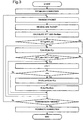
- the communication device 1 (hereinafter, referred to as a "transmission terminal") of the transmission side establishes a TCP connection between its own device 1 which is the transmission terminal and the counterpart communication device 2 (hereinafter, referred to as a "receive terminal") which is the receive side via the Internet 10 ( Fig. 3 : step S101) and starts transmission of transmission data ( Fig. 3 : step S102).
- an acknowledgement packet (an ACK packet) is returned from the receive terminal 2 in response to a packet transmitted from the transmission terminal 1
- the data receive unit 13 receives it ( Fig. 3 : step S103).
- the RTT calculation unit 14 obtains RTT received using the received ACK packet and, at the same time, the receive rate calculation unit 15 calculates a data receive rate RcvRate of the receive terminal 2 ( Fig. 3 : step S104).
- a congestion state i.e. network information to specify a transmission rate control mode required for data transmission
- a congestion state i.e. network information to specify a transmission rate control mode required for data transmission
- the transmission rate control mode specifying unit 16 determines that the transmission rate control mode is the transmission rate surge mode ( Fig. 2 : 105/ YES).
- said transmission rate control mode specifying unit 16 specifies said transmission rate control mode as the rate surge mode for rapidly increasing said transmission rate.
- the transmission rate control mode specifying unit 16 determines the transmission rate control mode to be the rate adjustment mode ( Fig. 2 : 107/YES).
- the transmission rate control mode specifying unit 16 specifies said transmission rate control mode to the rate adjustment mode for gradually increasing said transmission rate.
- the transmission rate control mode specifying unit 16 determines the transmission rate control mode to be the rate suppression mode when RTT_max ⁇ RTT ( Fig. 2 : 107/NO).
- said transmission rate control mode specifying unit 16 specifies said transmission rate control mode to the rate suppression mode for suppressing said transmission rate.
- the transmission terminal 1 repeats the means described above until data to be transmitted has run out ( Fig. 2 : 112) and finally disconnects the TCP connection to terminate the communication ( Fig. 2 : 113).
- the transmission rate control unit 18 does not perform a flow control based on the congestion window (CWND, Congestion Window) of TCP and continues to transmit data at the maximum transmission rate with R_lim as the upper limit as long as the buffer size (RWIN, Receive Window) of the receive buffer 13A in the data receive unit 13 of the receive side does not become zero.
- said transmission rate control unit 16 is configured to continue a transmission control of said data at the maximum transmission rate in a range not exceeding the upper limit value of said transmission rate as long as a free space of the buffer size of the receive buffer 13A in the data receive unit 13 provided in advance does not become zero.
- the transmission is interrupted until the receive buffer size of a value greater than zero is notified from the receive side to the transmission side ( Fig. 2 : 102).
- each operation step (a content execution step) described above, it may be configured such that the execution content is programmed so as to cause a computer provided in said communication device 1 in advance to implement it.
- the program may be recorded in a non-temporary storage medium, for example, a DVD, a CD, a flash memory or the like. In that case, the present program is retrieved from the storage medium by the computer to be executed.
- the transmission rate is not unnecessarily decreased even when a packet discard not caused by a congestion occurrence is detected, by measuring RTT and determining a transmission rate using the RTT as a reference.
- the transmission rate is not unnecessarily decreased even when an increase of RTT not caused by a congestion occurrence due to an automatic retransmission control of a wireless link layer or the like is generated.
- the rate adjustment mode in addition to the rate surge mode and the rate suppression mode as the transmission rate control modes, even if an error exists in estimating the RTT reference values (RTT_min and RTT_max), its effects can be made small.
- the throughput can be relatively easily improved since a mechanism for notifying special information from a network to a communication device is not required.
- the communication device 1 is configured and functions as described above and, therefore, data can be transmitted at a transmission rate suitable for a situation at the current time even when the communication line is, for example, a bottleneck line based on a utilization rate of the bottleneck line estimated using RTT (Round Trip Time) which is a transmission data response time and, accordingly, congestion can be avoided, while a band of the bottleneck line being effectively utilized, even in a communication environment in which random packet discards and packet error recovery delays may occur.
- RTT Random Trip Time
- the present invention may be applied, for example, to a relay device for relaying a session between the communication device 1 and the communication device 2 connected via a network.
- the relay device is to relay a communication session between the two terminals by once terminating a communication session with the communication device 1 of one side and then establishing a new communication session with the communication device 2 of the other side in the communication session between the two communication devices.
- a communication protocol suitable for implementing the present invention is TCP as described in the above exemplary embodiment, it is not limited to the TCP but may be of other communication protocol as long as it performs a congestion control.
- a communication device comprising: a transmission data output unit for outputting a predetermined amount of communication data toward a communication destination via a network; and a transmission rate control unit for controlling a data amount continuously transmittable to the network by drive-controlling the transmission data output unit,
- the transmission rate control unit comprises a transmission rate control function for controlling so as to keep continuously transmitting the transmission data in a range not exceeding an upper limit value of a specific transmission rate determined in advance.
- the transmission rate control unit is provided with a transmission rate control mode specifying unit for specifying a transmission rate control mode based on congestion information of the network and a transmission rate calculation unit for determining an upper limit value of a transmission rate according to the specified transmission rate control mode and the transmission rate control unit comprises a function of controlling an output operation of the transmission data output unit based on respective output information of the transmission rate control mode specifying unit and the transmission rate calculation unit.
- the transmission rate control mode specifying unit comprises a function of specifying the transmission rate control mode to any one of a rate surge mode for rapidly increasing the transmission rate, a rate adjustment mode for gradually increasing the transmission rate, and a rate suppression mode for suppressing the transmission rate based on congestion information of the network.
- the transmission rate control mode specifying unit comprises a control mode specifying function of specifying the transmission rate control mode depending on a signal propagation time in the network is short, normal, or long.
- the transmission rate control mode specifying unit comprises a function of specifying the transmission rate control mode to a rate surge mode for rapidly increasing the transmission rate when a signal propagation time at the current time becomes equal to or less than a minimum value of signal propagation times in the past.
- the transmission rate control mode specifying unit comprises a function of specifying the transmission rate control mode to a rate adjustment mode for gradually increasing the transmission rate when a signal propagation time at the current time becomes greater than a minimum value and less than a maximum value of signal propagation times in the past.
- the transmission rate control mode specifying unit comprises a function of specifying the transmission rate control mode to a rate suppression mode for suppressing the transmission rate when a signal propagation time at the current time becomes equal to or greater than a maximum value of signal propagation times in the past.
- the transmission rate control unit comprises a maximum rate transmission control function of continuing a transmission control of data at a maximum transmission rate in a range not exceeding a transmission rate upper limit value as long as a free space of a receive buffer size of a data receive unit provided in advance does not become zero.
- a transmission data output control method for a communication device comprising: a transmission data output unit for outputting a predetermined amount of communication data toward a communication destination via a network; and a transmission rate control unit for controlling a data amount continuously transmittable to the network by drive-controlling the transmission data output unit, wherein a transmission rate control mode specifying unit provided in advance specifies a transmission rate control mode required for transmitting the data based on congestion information obtained from the network, a transmission rate calculation unit provided in advance determines an upper limit value of a transmission rate according to the specified transmission rate control mode, and the transmission rate control unit drive-controls the transmission data output unit so as to keep continuously transmitting the transmission data in a range not exceeding the determined upper limit value of the transmission rate.
- the transmission rate control mode specifying unit specifies the transmission rate control mode to a rate surge mode for rapidly increasing the transmission rate when a signal propagation time in the network at the current time becomes equal to or less than a minimum value of signal propagation times in the past.
- the transmission rate control mode specifying unit specifies the transmission rate control mode to a rate adjustment mode for gradually increasing the transmission rate when a signal propagation time in the network at the current time becomes greater than a minimum value and less than a maximum value of signal propagation times in the past.
- the transmission rate control mode specifying unit specifies the transmission rate control mode to a rate suppression mode for suppressing the transmission rate when a signal propagation time in the network at the current time becomes equal to or greater than a maximum value of signal propagation times in the past.
- the transmission data control unit is configured to continue a transmission control of the data at a maximum transmission rate in a range not exceeding an upper limit value of the transmission rate as long as a free space of a receive buffer size of a data receive unit provided in advance does not become zero.
- a transmission data output control program for a communication device comprising: a transmission data output unit for outputting a predetermined amount of communication data toward a communication destination via a network; and a transmission rate control unit for controlling a data amount continuously transmittable to the network by drive-controlling the transmission data output unit, wherein a computer is caused to realize functions provided, the functions comprising:
- the transmission data output control program according to Supplementary Note 14, wherein the rate control mode specifying function for specifying the transmission rate control mode is configured to comprise a function for specifying the transmission rate control mode to a rate surge mode for rapidly increasing the transmission rate when a signal propagation time in the network at the current time becomes equal to or less than a minimum value of signal propagation times in the past and the computer is caused to realize the specifying process function.
- the rate control mode specifying function for specifying the transmission rate control mode is configured to comprise a function for specifying the transmission rate control mode to a rate adjustment mode for gradually increasing the transmission rate when a signal propagation time in the network at the current time becomes greater than a minimum value and less than a maximum value of signal propagation times in the past and the computer is caused to realize the specifying process function.
- the transmission data output control program wherein the rate control mode specifying function for specifying the transmission rate control mode is configured to comprise a function for specifying the transmission rate control mode to a rate suppression mode for suppressing the transmission rate when a signal propagation time in the network at the current time becomes equal to or greater than a maximum value of signal propagation times in the past and the computer is caused to realize the specifying process function.
- the output unit drive-control function for drive-controlling the transmission data output unit is configured to comprise a function for continuing a transmission control of the transmission data at a maximum transmission rate in a range not exceeding an upper limit value of a transmission rate as long as a free space of a receive buffer size of a data receive unit provided in advance does not become zero and the computer is caused to realize the control function.
- the present invention may be applied to a communication terminal, a communication relay device, a communication server device, respective systems relating to a wired communication and a wireless communication, and the like.
Claims (8)
- Dispositif de communication, comprenant : une unité de sortie de données de transmission (11) destinée à émettre une quantité définie de données de communication vers une destination de communication par l'intermédiaire d'un réseau (10) ; et une unité de commande de débit de transmission (18) destinée à commander une quantité de données transmissible en continu vers le réseau par contrôle de pilotage de l'unité de sortie de données de transmission (11),
où l'unité de commande de débit de transmission (18) comprend une fonction de commande de débit de transmission destinée à maintenir une transmission continue des données de transmission dans une plage ne dépassant pas une valeur limite supérieure d'un débit de transmission spécifique préalablement déterminé,
l'unité de commande de débit de transmission (18) est pourvue d'une unité de spécification du mode de commande de débit de transmission (16) destinée à spécifier un mode de commande de débit de transmission sur la base d'une information de congestion du réseau (18), et d'une unité de calcul de débit de transmission (17) destinée à déterminer une valeur limite supérieure d'un débit de transmission en fonction du mode de commande de débit de transmission spécifié, et
où l'unité de commande de débit de transmission (18) comprend une fonction de commande d'une opération de sortie de l'unité de sortie de données de transmission (11) sur la base d'une information de sortie respective de l'unité de spécification du mode de commande de débit de transmission (16) et de l'unité de calcul de débit de transmission (17),
caractérisé en ce que l'unité de spécification du mode de commande de débit de transmission (16) comprend une fonction de spécification du mode de commande de débit de transmission en un mode d'augmentation de débit pour une élévation rapide du débit de transmission, ou un mode d'ajustement de débit pour une élévation progressive du débit de transmission, ou un mode de suppression de débit pour un arrêt du débit de transmission sur la base de l'information de congestion du réseau (10). - Dispositif de communication selon la revendication 1, où
l'unité de spécification du mode de commande de débit de transmission (16) comprend une fonction de spécification de mode de commande, spécifiant le mode de commande de débit de transmission selon qu'une durée de propagation de signal dans le réseau (10) est brève, normale ou longue. - Dispositif de communication selon la revendication 1, où
l'unité de spécification du mode de commande de débit de transmission (16) comprend la fonction de spécification du mode de commande de débit de transmission en mode d'augmentation de débit pour une élévation rapide du débit de transmission quand une durée de propagation de signal au moment actuel devient égale ou inférieure à une valeur minimale de durée de propagation de signal passée. - Dispositif de communication selon la revendication 1, où
l'unité de spécification du mode de commande de débit de transmission (16) comprend la fonction de spécification du mode de commande de débit de transmission en mode d'ajustement de débit pour une élévation progressive du débit de transmission quand une durée de propagation de signal au moment actuel devient supérieure à une valeur minimale et inférieure à une valeur maximale de durée de propagation de signal passée. - Dispositif de communication selon la revendication 1, où
l'unité de spécification du mode de commande de débit de transmission (16) comprend la fonction de spécification du mode de commande de débit de transmission en mode de suppression de débit pour un arrêt du débit de transmission quand une durée de propagation de signal au moment actuel devient égale ou supérieure à une valeur maximale de durée de propagation de signal passée. - Dispositif de communication selon la revendication 1, où
l'unité de commande de débit de transmission (18) comprend une fonction de commande de transmission à débit maximum poursuivant une commande de transmission de données à débit de transmission maximum dans une plage ne dépassant pas une valeur limite supérieure de débit de transmission tant que la taille d'espace libre d'un tampon de réception d'une unité de réception de données préalablement prévue ne devient pas égale à zéro. - Procédé de commande de sortie de données de transmission pour un dispositif de communication comprenant : une unité de sortie de données de transmission (11) destinée à émettre une quantité définie de données de communication vers une destination de communication par l'intermédiaire d'un réseau (10) ; et une unité de commande de débit de transmission (18) destinée à commander une quantité de données transmissible en continu vers le réseau par contrôle de pilotage de l'unité de sortie de données de transmission (11), où
une unité de spécification du mode de commande de débit de transmission (16) préalablement prévue spécifie un mode de commande de débit de transmission exigé pour la transmission des données sur la base d'une information de congestion obtenue du réseau (10) en un mode d'augmentation de débit pour une élévation rapide du débit de transmission, ou un mode d'ajustement de débit pour une élévation progressive du débit de transmission, ou un mode de suppression de débit pour un arrêt du débit de transmission sur la base de l'information de congestion du réseau (10),
une unité de calcul de débit de transmission (17) préalablement prévue détermine une valeur limite supérieure d'un débit de transmission en fonction du mode de commande de débit de transmission spécifié, et
où l'unité de commande de débit de transmission (18) commande le pilotage de l'unité de sortie de données de transmission (11) de manière à maintenir une transmission continue des données de transmission dans une plage ne dépassant pas la valeur limite supérieure déterminée pour le débit de transmission spécifié. - Programme de commande de sortie de données de transmission pour un dispositif de communication comprenant : une unité de sortie de données de transmission (11) destinée à émettre une quantité définie de données de communication vers une destination de communication par l'intermédiaire d'un réseau (10) ; et une unité de commande de débit de transmission (18) destinée à commander une quantité de données transmissible en continu vers le réseau par contrôle de pilotage de l'unité de sortie de données de transmission (11), où
un ordinateur est entraîné à exécuter des fonctions prévues, lesdites fonctions comprenant :une fonction de spécification de mode de commande de débit destinée à spécifier un mode de commande de débit de transmission exigé pour une transmission de données sur la base d'une information de congestion du réseau (10), en un mode d'augmentation de débit pour une élévation rapide du débit de transmission, ou un mode d'ajustement de débit pour une élévation progressive du débit de transmission, ou un mode de suppression de débit pour un arrêt du débit de transmission sur la base de l'information de congestion du réseau (10) ;une fonction de détermination de valeur limite supérieure de débit de transmission destinée à déterminer une valeur limite supérieure d'un débit de transmission en fonction du mode de commande de débit de transmission spécifié ; etune fonction de commande de pilotage d'unité de sortie destinée à commander le pilotage de l'unité de sortie de données de transmission de manière à maintenir une transmission continue des données de transmission dans une plage ne dépassant pas la valeur limite supérieure déterminée pour le débit de transmission spécifié.
Applications Claiming Priority (2)
| Application Number | Priority Date | Filing Date | Title |
|---|---|---|---|
| JP2012243363 | 2012-11-05 | ||
| PCT/JP2013/079785 WO2014069642A1 (fr) | 2012-11-05 | 2013-11-01 | Dispositif de communication, procédé de commande de sortie de données de transmission, et leur programme |
Publications (3)
| Publication Number | Publication Date |
|---|---|
| EP2916521A1 EP2916521A1 (fr) | 2015-09-09 |
| EP2916521A4 EP2916521A4 (fr) | 2016-06-29 |
| EP2916521B1 true EP2916521B1 (fr) | 2018-02-21 |
Family
ID=50627534
Family Applications (1)
| Application Number | Title | Priority Date | Filing Date |
|---|---|---|---|
| EP13850413.9A Not-in-force EP2916521B1 (fr) | 2012-11-05 | 2013-11-01 | Dispositif de communication, procédé de commande de sortie de données de transmission, et leur programme |
Country Status (4)
| Country | Link |
|---|---|
| US (1) | US9674101B2 (fr) |
| EP (1) | EP2916521B1 (fr) |
| JP (1) | JPWO2014069642A1 (fr) |
| WO (1) | WO2014069642A1 (fr) |
Families Citing this family (10)
| Publication number | Priority date | Publication date | Assignee | Title |
|---|---|---|---|---|
| US9992120B2 (en) * | 2015-10-21 | 2018-06-05 | Citrix Systems, Inc. | System and method for rate-based packet transmission over a network |
| JP6698183B2 (ja) * | 2016-07-01 | 2020-05-27 | テレフオンアクチーボラゲット エルエム エリクソン(パブル) | ラウンドトリップタイムスキュー制御の方法および装置 |
| CN115589617A (zh) * | 2016-11-03 | 2023-01-10 | 松下电器(美国)知识产权公司 | 无线通信装置和方法 |
| US10567300B2 (en) * | 2017-11-22 | 2020-02-18 | Cisco Technology, Inc. | Layer 3 fair rate congestion control notification |
| JP7043808B2 (ja) | 2017-11-30 | 2022-03-30 | 富士通株式会社 | 通信装置、通信システム、および通信速度制御方法 |
| CN108494698B (zh) * | 2017-12-13 | 2022-02-25 | 天地伟业技术有限公司 | 一种基于传输速率的拥塞控制方法 |
| KR102139378B1 (ko) * | 2018-11-20 | 2020-07-29 | 울산과학기술원 | 혼잡 제어 방법 및 장치 |
| US11296988B2 (en) | 2019-11-14 | 2022-04-05 | Mellanox Technologies, Ltd. | Programmable congestion control communication scheme |
| US11218413B2 (en) * | 2019-11-14 | 2022-01-04 | Mellanox Technologies, Ltd. | Congestion control management method derived from packets at a network adapter |
| EP3952254A1 (fr) * | 2020-08-06 | 2022-02-09 | Mellanox Technologies, Ltd. | Schéma de communication programmable pour la régulation d'encombrement |
Family Cites Families (16)
| Publication number | Priority date | Publication date | Assignee | Title |
|---|---|---|---|---|
| JP4101993B2 (ja) | 1999-12-03 | 2008-06-18 | 三菱電機株式会社 | 有線無線混在網データ配信装置及び有線無線混在網データ配信方法 |
| US20020075895A1 (en) * | 2000-10-27 | 2002-06-20 | Takao Yamaguchi | Transmission rate controller and transmission rate control method |
| JP4351418B2 (ja) | 2002-04-26 | 2009-10-28 | 株式会社エヌ・ティ・ティ・ドコモ | マルチメディアストリーミング送出レート制御方法および装置 |
| JP3665309B2 (ja) | 2002-08-19 | 2005-06-29 | 株式会社国際電気通信基礎技術研究所 | 通信システム、通信装置及び通信方法 |
| KR100526187B1 (ko) | 2003-10-18 | 2005-11-03 | 삼성전자주식회사 | 모바일 애드 혹 네트워크 환경에서 최적의 전송율을 찾기위한 조절 방법 |
| JP4362761B2 (ja) | 2003-10-29 | 2009-11-11 | ソニー株式会社 | 送信装置および方法、記録媒体、並びにプログラム |
| US8125910B2 (en) * | 2004-06-25 | 2012-02-28 | Nec Corporation | Communication system |
| JP4147534B2 (ja) | 2005-02-03 | 2008-09-10 | 日本電気株式会社 | 通信装置および通信方法 |
| JP4643330B2 (ja) * | 2005-03-28 | 2011-03-02 | ソニー株式会社 | 通信処理装置、データ通信システム、および通信処理方法、並びにコンピュータ・プログラム |
| JP4407700B2 (ja) | 2007-02-02 | 2010-02-03 | 日本電気株式会社 | 通信端末、通信システム、輻輳制御方法、及び輻輳制御用プログラム |
| CN104883322B (zh) | 2009-01-16 | 2019-07-12 | 主线网络控股有限公司 | 经由网络通过计算机传输数据而同时避免阻塞的方法及连接至网络的计算系统 |
| JP5652388B2 (ja) * | 2009-03-06 | 2015-01-14 | 日本電気株式会社 | 通信レート制御方法、送信装置および通信システム |
| JP5375416B2 (ja) | 2009-08-03 | 2013-12-25 | 日本電気株式会社 | ストリーム配信装置、ストリーム配信システム、ストリーム配信方法およびストリーム配信プログラム |
| CN102656866B (zh) * | 2009-12-14 | 2015-03-11 | 日本电气株式会社 | 通信设备和通信控制方法 |
| US9444688B2 (en) * | 2011-10-04 | 2016-09-13 | North Carolina State University | Receiver-based methods, systems, and computer readable media for controlling TCP sender behavior in mobile communications networks with large buffer sizes |
| US8923270B2 (en) * | 2011-10-04 | 2014-12-30 | The Chinese University Of Hong Kong | Method for link buffer size and queue length estimation for bandwidth-varying mobile data networks |
-
2013
- 2013-11-01 EP EP13850413.9A patent/EP2916521B1/fr not_active Not-in-force
- 2013-11-01 JP JP2014544614A patent/JPWO2014069642A1/ja active Pending
- 2013-11-01 US US14/440,003 patent/US9674101B2/en not_active Expired - Fee Related
- 2013-11-01 WO PCT/JP2013/079785 patent/WO2014069642A1/fr active Application Filing
Non-Patent Citations (1)
| Title |
|---|
| None * |
Also Published As
| Publication number | Publication date |
|---|---|
| EP2916521A1 (fr) | 2015-09-09 |
| US9674101B2 (en) | 2017-06-06 |
| EP2916521A4 (fr) | 2016-06-29 |
| WO2014069642A1 (fr) | 2014-05-08 |
| JPWO2014069642A1 (ja) | 2016-09-08 |
| US20150304226A1 (en) | 2015-10-22 |
Similar Documents
| Publication | Publication Date | Title |
|---|---|---|
| EP2916521B1 (fr) | Dispositif de communication, procédé de commande de sortie de données de transmission, et leur programme | |
| JP4147534B2 (ja) | 通信装置および通信方法 | |
| JP4708978B2 (ja) | 高スループットを実現する通信システム、通信端末、セッション中継装置、及び通信プロトコル | |
| US9641650B2 (en) | TCP proxy server | |
| CN105264843B (zh) | 在通信设备中管理待发送的确认数据包 | |
| JP5625748B2 (ja) | 通信装置、通信システム、プログラム及び通信方法 | |
| JP5867188B2 (ja) | 情報処理装置、輻輳制御方法および輻輳制御プログラム | |
| EP2938032B1 (fr) | Dispositif de transmission de données, procédé de transmission de données, et programme associé | |
| US9515939B2 (en) | Apparatus and method for controlling a window size of packet transmission based on a free space of buffer | |
| KR101741003B1 (ko) | 중복된 애크를 이용한 통신 방법 | |
| US8279756B2 (en) | Communication terminal, communication control method, and communication control program | |
| CN108432287A (zh) | 一种数据传输方法及网络侧设备 | |
| JP2008053888A (ja) | 通信装置、プログラム、情報記憶媒体および通信制御方法 | |
| JP6217424B2 (ja) | 制御装置及び制御方法 | |
| JP6011813B2 (ja) | 通信装置およびその通信制御方法 | |
| JP5748615B2 (ja) | 通信装置 | |
| WO2019146563A1 (fr) | Dispositif de communication, système de communication, procédé de communication, et programme | |
| KR100915996B1 (ko) | 대역폭변화에 따른 적응형 전송 제어 프로토콜을 이용한데이터 패킷 전송 방법 및 그를 위한 송신측 단말장치 | |
| WO2013011638A1 (fr) | Dispositif de communication et son procédé de commande de communication | |
| WO2016147650A1 (fr) | Appareil d'émission et procédé de commande associé, système de communication, et support d'enregistrement pour stocker un programme de commande de communication | |
| JP2017158047A (ja) | 中継装置、中継方法及び中継プログラム |
Legal Events
| Date | Code | Title | Description |
|---|---|---|---|
| PUAI | Public reference made under article 153(3) epc to a published international application that has entered the european phase |
Free format text: ORIGINAL CODE: 0009012 |
|
| 17P | Request for examination filed |
Effective date: 20150523 |
|
| AK | Designated contracting states |
Kind code of ref document: A1 Designated state(s): AL AT BE BG CH CY CZ DE DK EE ES FI FR GB GR HR HU IE IS IT LI LT LU LV MC MK MT NL NO PL PT RO RS SE SI SK SM TR |
|
| AX | Request for extension of the european patent |
Extension state: BA ME |
|
| DAX | Request for extension of the european patent (deleted) | ||
| RA4 | Supplementary search report drawn up and despatched (corrected) |
Effective date: 20160601 |
|
| RIC1 | Information provided on ipc code assigned before grant |
Ipc: H04W 28/10 20090101ALI20160525BHEP Ipc: H04L 29/08 20060101AFI20160525BHEP Ipc: H04L 12/825 20130101ALI20160525BHEP Ipc: H04W 80/06 20090101ALI20160525BHEP Ipc: H04L 12/841 20130101ALI20160525BHEP |
|
| GRAP | Despatch of communication of intention to grant a patent |
Free format text: ORIGINAL CODE: EPIDOSNIGR1 |
|
| RIC1 | Information provided on ipc code assigned before grant |
Ipc: H04W 80/06 20090101ALI20170523BHEP Ipc: H04W 28/10 20090101ALI20170523BHEP Ipc: H04L 29/08 20060101AFI20170523BHEP Ipc: H04L 12/825 20130101ALI20170523BHEP Ipc: H04L 12/841 20130101ALI20170523BHEP |
|
| INTG | Intention to grant announced |
Effective date: 20170622 |
|
| GRAS | Grant fee paid |
Free format text: ORIGINAL CODE: EPIDOSNIGR3 |
|
| GRAJ | Information related to disapproval of communication of intention to grant by the applicant or resumption of examination proceedings by the epo deleted |
Free format text: ORIGINAL CODE: EPIDOSDIGR1 |
|
| GRAL | Information related to payment of fee for publishing/printing deleted |
Free format text: ORIGINAL CODE: EPIDOSDIGR3 |
|
| INTC | Intention to grant announced (deleted) | ||
| GRAP | Despatch of communication of intention to grant a patent |
Free format text: ORIGINAL CODE: EPIDOSNIGR1 |
|
| INTG | Intention to grant announced |
Effective date: 20171130 |
|
| GRAA | (expected) grant |
Free format text: ORIGINAL CODE: 0009210 |
|
| AK | Designated contracting states |
Kind code of ref document: B1 Designated state(s): AL AT BE BG CH CY CZ DE DK EE ES FI FR GB GR HR HU IE IS IT LI LT LU LV MC MK MT NL NO PL PT RO RS SE SI SK SM TR |
|
| REG | Reference to a national code |
Ref country code: GB Ref legal event code: FG4D |
|
| REG | Reference to a national code |
Ref country code: CH Ref legal event code: EP |
|
| REG | Reference to a national code |
Ref country code: AT Ref legal event code: REF Ref document number: 972904 Country of ref document: AT Kind code of ref document: T Effective date: 20180315 |
|
| REG | Reference to a national code |
Ref country code: IE Ref legal event code: FG4D |
|
| REG | Reference to a national code |
Ref country code: DE Ref legal event code: R096 Ref document number: 602013033511 Country of ref document: DE |
|
| REG | Reference to a national code |
Ref country code: NL Ref legal event code: MP Effective date: 20180221 |
|
| REG | Reference to a national code |
Ref country code: LT Ref legal event code: MG4D |
|
| REG | Reference to a national code |
Ref country code: AT Ref legal event code: MK05 Ref document number: 972904 Country of ref document: AT Kind code of ref document: T Effective date: 20180221 |
|
| PG25 | Lapsed in a contracting state [announced via postgrant information from national office to epo] |
Ref country code: NO Free format text: LAPSE BECAUSE OF FAILURE TO SUBMIT A TRANSLATION OF THE DESCRIPTION OR TO PAY THE FEE WITHIN THE PRESCRIBED TIME-LIMIT Effective date: 20180521 Ref country code: FI Free format text: LAPSE BECAUSE OF FAILURE TO SUBMIT A TRANSLATION OF THE DESCRIPTION OR TO PAY THE FEE WITHIN THE PRESCRIBED TIME-LIMIT Effective date: 20180221 Ref country code: NL Free format text: LAPSE BECAUSE OF FAILURE TO SUBMIT A TRANSLATION OF THE DESCRIPTION OR TO PAY THE FEE WITHIN THE PRESCRIBED TIME-LIMIT Effective date: 20180221 Ref country code: CY Free format text: LAPSE BECAUSE OF FAILURE TO SUBMIT A TRANSLATION OF THE DESCRIPTION OR TO PAY THE FEE WITHIN THE PRESCRIBED TIME-LIMIT Effective date: 20180221 Ref country code: LT Free format text: LAPSE BECAUSE OF FAILURE TO SUBMIT A TRANSLATION OF THE DESCRIPTION OR TO PAY THE FEE WITHIN THE PRESCRIBED TIME-LIMIT Effective date: 20180221 Ref country code: HR Free format text: LAPSE BECAUSE OF FAILURE TO SUBMIT A TRANSLATION OF THE DESCRIPTION OR TO PAY THE FEE WITHIN THE PRESCRIBED TIME-LIMIT Effective date: 20180221 Ref country code: ES Free format text: LAPSE BECAUSE OF FAILURE TO SUBMIT A TRANSLATION OF THE DESCRIPTION OR TO PAY THE FEE WITHIN THE PRESCRIBED TIME-LIMIT Effective date: 20180221 |
|
| PG25 | Lapsed in a contracting state [announced via postgrant information from national office to epo] |
Ref country code: BG Free format text: LAPSE BECAUSE OF FAILURE TO SUBMIT A TRANSLATION OF THE DESCRIPTION OR TO PAY THE FEE WITHIN THE PRESCRIBED TIME-LIMIT Effective date: 20180521 Ref country code: GR Free format text: LAPSE BECAUSE OF FAILURE TO SUBMIT A TRANSLATION OF THE DESCRIPTION OR TO PAY THE FEE WITHIN THE PRESCRIBED TIME-LIMIT Effective date: 20180522 Ref country code: RS Free format text: LAPSE BECAUSE OF FAILURE TO SUBMIT A TRANSLATION OF THE DESCRIPTION OR TO PAY THE FEE WITHIN THE PRESCRIBED TIME-LIMIT Effective date: 20180221 Ref country code: AT Free format text: LAPSE BECAUSE OF FAILURE TO SUBMIT A TRANSLATION OF THE DESCRIPTION OR TO PAY THE FEE WITHIN THE PRESCRIBED TIME-LIMIT Effective date: 20180221 Ref country code: SE Free format text: LAPSE BECAUSE OF FAILURE TO SUBMIT A TRANSLATION OF THE DESCRIPTION OR TO PAY THE FEE WITHIN THE PRESCRIBED TIME-LIMIT Effective date: 20180221 Ref country code: LV Free format text: LAPSE BECAUSE OF FAILURE TO SUBMIT A TRANSLATION OF THE DESCRIPTION OR TO PAY THE FEE WITHIN THE PRESCRIBED TIME-LIMIT Effective date: 20180221 |
|
| PG25 | Lapsed in a contracting state [announced via postgrant information from national office to epo] |
Ref country code: EE Free format text: LAPSE BECAUSE OF FAILURE TO SUBMIT A TRANSLATION OF THE DESCRIPTION OR TO PAY THE FEE WITHIN THE PRESCRIBED TIME-LIMIT Effective date: 20180221 Ref country code: PL Free format text: LAPSE BECAUSE OF FAILURE TO SUBMIT A TRANSLATION OF THE DESCRIPTION OR TO PAY THE FEE WITHIN THE PRESCRIBED TIME-LIMIT Effective date: 20180221 Ref country code: RO Free format text: LAPSE BECAUSE OF FAILURE TO SUBMIT A TRANSLATION OF THE DESCRIPTION OR TO PAY THE FEE WITHIN THE PRESCRIBED TIME-LIMIT Effective date: 20180221 Ref country code: IT Free format text: LAPSE BECAUSE OF FAILURE TO SUBMIT A TRANSLATION OF THE DESCRIPTION OR TO PAY THE FEE WITHIN THE PRESCRIBED TIME-LIMIT Effective date: 20180221 Ref country code: AL Free format text: LAPSE BECAUSE OF FAILURE TO SUBMIT A TRANSLATION OF THE DESCRIPTION OR TO PAY THE FEE WITHIN THE PRESCRIBED TIME-LIMIT Effective date: 20180221 |
|
| REG | Reference to a national code |
Ref country code: DE Ref legal event code: R097 Ref document number: 602013033511 Country of ref document: DE |
|
| PG25 | Lapsed in a contracting state [announced via postgrant information from national office to epo] |
Ref country code: DK Free format text: LAPSE BECAUSE OF FAILURE TO SUBMIT A TRANSLATION OF THE DESCRIPTION OR TO PAY THE FEE WITHIN THE PRESCRIBED TIME-LIMIT Effective date: 20180221 Ref country code: SK Free format text: LAPSE BECAUSE OF FAILURE TO SUBMIT A TRANSLATION OF THE DESCRIPTION OR TO PAY THE FEE WITHIN THE PRESCRIBED TIME-LIMIT Effective date: 20180221 Ref country code: SM Free format text: LAPSE BECAUSE OF FAILURE TO SUBMIT A TRANSLATION OF THE DESCRIPTION OR TO PAY THE FEE WITHIN THE PRESCRIBED TIME-LIMIT Effective date: 20180221 Ref country code: CZ Free format text: LAPSE BECAUSE OF FAILURE TO SUBMIT A TRANSLATION OF THE DESCRIPTION OR TO PAY THE FEE WITHIN THE PRESCRIBED TIME-LIMIT Effective date: 20180221 |
|
| PLBE | No opposition filed within time limit |
Free format text: ORIGINAL CODE: 0009261 |
|
| STAA | Information on the status of an ep patent application or granted ep patent |
Free format text: STATUS: NO OPPOSITION FILED WITHIN TIME LIMIT |
|
| 26N | No opposition filed |
Effective date: 20181122 |
|
| PG25 | Lapsed in a contracting state [announced via postgrant information from national office to epo] |
Ref country code: SI Free format text: LAPSE BECAUSE OF FAILURE TO SUBMIT A TRANSLATION OF THE DESCRIPTION OR TO PAY THE FEE WITHIN THE PRESCRIBED TIME-LIMIT Effective date: 20180221 |
|
| REG | Reference to a national code |
Ref country code: CH Ref legal event code: PL |
|
| GBPC | Gb: european patent ceased through non-payment of renewal fee |
Effective date: 20181101 |
|
| PG25 | Lapsed in a contracting state [announced via postgrant information from national office to epo] |
Ref country code: LU Free format text: LAPSE BECAUSE OF NON-PAYMENT OF DUE FEES Effective date: 20181101 Ref country code: MC Free format text: LAPSE BECAUSE OF FAILURE TO SUBMIT A TRANSLATION OF THE DESCRIPTION OR TO PAY THE FEE WITHIN THE PRESCRIBED TIME-LIMIT Effective date: 20180221 |
|
| REG | Reference to a national code |
Ref country code: BE Ref legal event code: MM Effective date: 20181130 |
|
| REG | Reference to a national code |
Ref country code: IE Ref legal event code: MM4A |
|
| PG25 | Lapsed in a contracting state [announced via postgrant information from national office to epo] |
Ref country code: CH Free format text: LAPSE BECAUSE OF NON-PAYMENT OF DUE FEES Effective date: 20181130 Ref country code: LI Free format text: LAPSE BECAUSE OF NON-PAYMENT OF DUE FEES Effective date: 20181130 |
|
| PG25 | Lapsed in a contracting state [announced via postgrant information from national office to epo] |
Ref country code: IE Free format text: LAPSE BECAUSE OF NON-PAYMENT OF DUE FEES Effective date: 20181101 Ref country code: FR Free format text: LAPSE BECAUSE OF NON-PAYMENT OF DUE FEES Effective date: 20181130 |
|
| PG25 | Lapsed in a contracting state [announced via postgrant information from national office to epo] |
Ref country code: BE Free format text: LAPSE BECAUSE OF NON-PAYMENT OF DUE FEES Effective date: 20181130 |
|
| PG25 | Lapsed in a contracting state [announced via postgrant information from national office to epo] |
Ref country code: GB Free format text: LAPSE BECAUSE OF NON-PAYMENT OF DUE FEES Effective date: 20181101 |
|
| PG25 | Lapsed in a contracting state [announced via postgrant information from national office to epo] |
Ref country code: MT Free format text: LAPSE BECAUSE OF NON-PAYMENT OF DUE FEES Effective date: 20181101 |
|
| PGFP | Annual fee paid to national office [announced via postgrant information from national office to epo] |
Ref country code: DE Payment date: 20191022 Year of fee payment: 7 |
|
| PG25 | Lapsed in a contracting state [announced via postgrant information from national office to epo] |
Ref country code: TR Free format text: LAPSE BECAUSE OF FAILURE TO SUBMIT A TRANSLATION OF THE DESCRIPTION OR TO PAY THE FEE WITHIN THE PRESCRIBED TIME-LIMIT Effective date: 20180221 |
|
| PG25 | Lapsed in a contracting state [announced via postgrant information from national office to epo] |
Ref country code: PT Free format text: LAPSE BECAUSE OF FAILURE TO SUBMIT A TRANSLATION OF THE DESCRIPTION OR TO PAY THE FEE WITHIN THE PRESCRIBED TIME-LIMIT Effective date: 20180221 |
|
| PG25 | Lapsed in a contracting state [announced via postgrant information from national office to epo] |
Ref country code: MK Free format text: LAPSE BECAUSE OF NON-PAYMENT OF DUE FEES Effective date: 20180221 Ref country code: HU Free format text: LAPSE BECAUSE OF FAILURE TO SUBMIT A TRANSLATION OF THE DESCRIPTION OR TO PAY THE FEE WITHIN THE PRESCRIBED TIME-LIMIT; INVALID AB INITIO Effective date: 20131101 |
|
| PG25 | Lapsed in a contracting state [announced via postgrant information from national office to epo] |
Ref country code: IS Free format text: LAPSE BECAUSE OF FAILURE TO SUBMIT A TRANSLATION OF THE DESCRIPTION OR TO PAY THE FEE WITHIN THE PRESCRIBED TIME-LIMIT Effective date: 20180621 |
|
| REG | Reference to a national code |
Ref country code: DE Ref legal event code: R119 Ref document number: 602013033511 Country of ref document: DE |
|
| PG25 | Lapsed in a contracting state [announced via postgrant information from national office to epo] |
Ref country code: DE Free format text: LAPSE BECAUSE OF NON-PAYMENT OF DUE FEES Effective date: 20210601 |