EP2916521B1 - Communication device, transmission data output control method, and program for same - Google Patents
Communication device, transmission data output control method, and program for same Download PDFInfo
- Publication number
- EP2916521B1 EP2916521B1 EP13850413.9A EP13850413A EP2916521B1 EP 2916521 B1 EP2916521 B1 EP 2916521B1 EP 13850413 A EP13850413 A EP 13850413A EP 2916521 B1 EP2916521 B1 EP 2916521B1
- Authority
- EP
- European Patent Office
- Prior art keywords
- transmission rate
- transmission
- rate control
- control mode
- unit
- Prior art date
- Legal status (The legal status is an assumption and is not a legal conclusion. Google has not performed a legal analysis and makes no representation as to the accuracy of the status listed.)
- Not-in-force
Links
Images


Classifications
-
- H—ELECTRICITY
- H04—ELECTRIC COMMUNICATION TECHNIQUE
- H04L—TRANSMISSION OF DIGITAL INFORMATION, e.g. TELEGRAPHIC COMMUNICATION
- H04L47/00—Traffic control in data switching networks
- H04L47/10—Flow control; Congestion control
- H04L47/32—Flow control; Congestion control by discarding or delaying data units, e.g. packets or frames
-
- H—ELECTRICITY
- H04—ELECTRIC COMMUNICATION TECHNIQUE
- H04L—TRANSMISSION OF DIGITAL INFORMATION, e.g. TELEGRAPHIC COMMUNICATION
- H04L47/00—Traffic control in data switching networks
- H04L47/10—Flow control; Congestion control
- H04L47/22—Traffic shaping
-
- H—ELECTRICITY
- H04—ELECTRIC COMMUNICATION TECHNIQUE
- H04L—TRANSMISSION OF DIGITAL INFORMATION, e.g. TELEGRAPHIC COMMUNICATION
- H04L47/00—Traffic control in data switching networks
- H04L47/10—Flow control; Congestion control
- H04L47/12—Avoiding congestion; Recovering from congestion
-
- H—ELECTRICITY
- H04—ELECTRIC COMMUNICATION TECHNIQUE
- H04L—TRANSMISSION OF DIGITAL INFORMATION, e.g. TELEGRAPHIC COMMUNICATION
- H04L47/00—Traffic control in data switching networks
- H04L47/10—Flow control; Congestion control
- H04L47/25—Flow control; Congestion control with rate being modified by the source upon detecting a change of network conditions
-
- H—ELECTRICITY
- H04—ELECTRIC COMMUNICATION TECHNIQUE
- H04L—TRANSMISSION OF DIGITAL INFORMATION, e.g. TELEGRAPHIC COMMUNICATION
- H04L69/00—Network arrangements, protocols or services independent of the application payload and not provided for in the other groups of this subclass
- H04L69/16—Implementation or adaptation of Internet protocol [IP], of transmission control protocol [TCP] or of user datagram protocol [UDP]
- H04L69/163—In-band adaptation of TCP data exchange; In-band control procedures
-
- H—ELECTRICITY
- H04—ELECTRIC COMMUNICATION TECHNIQUE
- H04L—TRANSMISSION OF DIGITAL INFORMATION, e.g. TELEGRAPHIC COMMUNICATION
- H04L47/00—Traffic control in data switching networks
- H04L47/10—Flow control; Congestion control
- H04L47/19—Flow control; Congestion control at layers above the network layer
- H04L47/193—Flow control; Congestion control at layers above the network layer at the transport layer, e.g. TCP related
-
- H—ELECTRICITY
- H04—ELECTRIC COMMUNICATION TECHNIQUE
- H04L—TRANSMISSION OF DIGITAL INFORMATION, e.g. TELEGRAPHIC COMMUNICATION
- H04L47/00—Traffic control in data switching networks
- H04L47/10—Flow control; Congestion control
- H04L47/27—Evaluation or update of window size, e.g. using information derived from acknowledged [ACK] packets
-
- H—ELECTRICITY
- H04—ELECTRIC COMMUNICATION TECHNIQUE
- H04L—TRANSMISSION OF DIGITAL INFORMATION, e.g. TELEGRAPHIC COMMUNICATION
- H04L47/00—Traffic control in data switching networks
- H04L47/10—Flow control; Congestion control
- H04L47/28—Flow control; Congestion control in relation to timing considerations
-
- H—ELECTRICITY
- H04—ELECTRIC COMMUNICATION TECHNIQUE
- H04W—WIRELESS COMMUNICATION NETWORKS
- H04W8/00—Network data management
- H04W8/02—Processing of mobility data, e.g. registration information at HLR [Home Location Register] or VLR [Visitor Location Register]; Transfer of mobility data, e.g. between HLR, VLR or external networks
- H04W8/04—Registration at HLR or HSS [Home Subscriber Server]
Description
- The present invention relates to a communication device or the like for performing a communication session via a network and, in particular, relates to a communication device, a transmission data output control method, and a program for same which use a communication protocol having a congestion control function such as TCP (Transmission Control Protocol).
- Currently, in communication using TCP (Transmission Control Protocol) which is widely used as a communication protocol for safely and accurately transmitting a large amount of data via the Internet, a window control is used in order to perform efficient data transfer.
- In the window control, first of all, a data receive side notifies a receive buffer size (RWIN, Receive Window) to a data transmission side. The data transmission side may transmit an amount of data of the receive buffer size (RWIN) without waiting for an acknowledgement (ACK) of the receive side.
- In this case, when RWIN is too small compared to a line speed, a throughput is decreased due to deterioration of data transfer efficiency. Furthermore, when RWIN is too large compared to the line speed, the throughput is decreased since it takes time for retransmission processing due to data loss.
- TCP which is the above communication protocol includes a congestion control function for appropriately adjusting a congestion window (CWND, Congestion Window) according to a congestion condition of a network. The congestion control function of the TCP includes a function which always checks a communication state and configures to increase a transmission band by increasing the congestion window when congestion does not exist in the network and to decrease the transmission band by decreasing the congestion window when congestion exists in the network.
- As an example of TCP versions employing such a congestion control function, there is TCP-Reno (NPL 1). In the TCP-Reno, when an occurrence of a packet discard is detected in a congestion avoidance operation, it is determined that the network is in a congestion state and the congestion window is reduced to a half of the current one and, thereby, the transmission band is decreased.
- On the other hand, when an occurrence of a packet discard is not detected, it is determined that the network is not in the congestion state and the transmission band is slowly increased by linearly increasing the congestion window by 1 MMS (Maximum Segment Size).
- Incidentally, TCP-Reno has a problem that an originally-expected throughput cannot be obtained subsequently until the window size is increased to a sufficient size since it once halves the size of the congestion window when a packet discard occurs.
- This is a serious problem especially for wireless lines or the like in which a packet discard may occur due to causes other than congestion. In other words, despite a packet discard not caused by congestion, the TCP throughput is unnecessarily decreased.
- Furthermore, since TCP-Reno does not transmit next data until ACK is returned as an acknowledgement after transmitting an amount of data of the window size, the TCP throughput is unnecessarily decreased when RTT (Round Trip Time) as a transmission data response time becomes large.
- For example, in wireless lines to which communication methods such as WiMAX (Worldwide Interoperability for Microwave Access), HSPA (High Speed Packet Access), LTE (Long Term Evolution) are applied, errors may occur in a wireless link layer between a mobile terminal and a base station. Thus, when a packet discard occurs due to a cause other than congestion, the TCP throughput is unnecessarily decreased.
- On the other hand, as a technical method for recovering the errors, an automatic repeat request (ARQ: Automatic Repeat Request) for automatically retransmitting in the wireless link layer between the mobile terminal and the base station may be used. In this case, although it is possible to prevent a packet discard, an increase of RTT not caused by congestion in response to a time required for the automatic repeat request occurs and at the same time the TCP throughput is unnecessarily decreased.
- A technology described in
PTL 1 has been known as a related technology which provides some information from the network to the terminal whether or not the packet discards are caused by congestion when the packet discards occur (a first related technology). - In other words,
PTL 1 in which the first related technology is described discloses a technology in which, when a packet discard due to an error of the line occurs, ELN (Explicit Loss Notification) information is transmitted from a receive terminal to a transmission terminal and the transmission terminal does not unnecessarily decrease the congestion window when the packet discard is not due to congestion. - In addition, a technology described in
PTL 2 has been known as a related technology which performs a congestion determination using information a TCP transmission terminal has and takes a corresponding measure instead of immediately determining that the packet discard occurrence described above is a congestion occurrence (a second related technology). - In other words,
PTL 2 in which the second related technology is described discloses a technology in which the congestion window is not decreased even when a packet discard is detected, by first measuring RTT of the line and determining that there is no congestion when the RTT is equal to or less than a certain value. - Furthermore, as a third related technology, for example, PTL 3 discloses a technology in which a communication device for performing a communication session based on a congestion window estimates a utilization rate of a bottleneck line from RTT in the communication session, determines an increment of the congestion window in a congestion avoidance operation based on the estimated line utilization rate, and determines a size of the congestion window to be applied based on said increment when the congestion window is increased.
- In addition, PTL 4, in which a fourth related technology is described, discloses a technology in which a retransmission packet is transmitted to more reliably reach to a receiver by properly controlling a transmission rate.
- Furthermore, PTL 5, in which a fifth related technology is described, discloses a transmission technology which realizes an effective rate control in consideration of characteristics of a wireless environment by performing a rate control based on network information in the wireless environment.
-
- PTL 1: Japanese Laid-open Patent Publication No.
2004-080413 2001-160824 - PTL 3: Japanese Laid-open Patent Publication No.
2006-217234 - PTL 4: Japanese Laid-open Patent Publication No.
2005-136548 - PTL 5 Japanese Laid-open Patent Publication No.
2003-318979 - NPL 1: W. Stevens, "TCP Slow Start, Congestion Avoidance, Fast Retransmit, and Fast Recovery Algorithms," IETF RFC2001, http://www.ietf.org/rfc/rfc2001.txt, January 1997. [Searched August 30, 2012]. A transmission rate control method is also disclosed in the patent publication
EP1708438A1 . - A problem of the first related technology described above is that its installation is difficult since it is necessary to provide in a network a mechanism to notify a state of a wireless line and a cause of a packet discard to a terminal.
- In particular, when a terminal connected to a wireless line and unspecified number of terminals not connected to the wireless line performs communication, it is not easy to install said mechanisms to all of the unspecified number of terminals of the latter. Furthermore, it is difficult to apply similar mechanisms to wired lines.
- A problem of the second related technology is that congestion determination based on RTT as the response time described above is uncertain. Since a range of values RTT can take depends on a buffer capacity of a router, it is difficult to uniquely determine the optimal RTT threshold value used for the congestion determination.
- In other words, since the larger the buffer capacity of the router is, the larger the range of values RTT can take becomes, it is easily determined as a congestion occurrence when a line of a router with a relatively small buffer capacity is used rather than a line of a router with a relatively large buffer capacity even if one RTT threshold value is set in a terminal.
- Then, it may be determined as a congestion occurrence in spite of being actually minor congestion and as a result, the throughput is decreased by unnecessary reduction control of the congestion window. Conversely, when the buffer capacity is relatively large, it may be determined that congestion has not occurred yet for a state to be determined as a congestion occurrence, where, a problem occurs that a congestion window to be reduced is not reduced and as a result, congestion cannot be avoided. Furthermore, even if the congestion window could be appropriately controlled, the TCP throughput is unnecessarily decreased due to an increase of RTT not caused by congestion.
- Furthermore, a problem of the third related technology is uncertainty of the estimation of the bottleneck line utilization rate based on RTT. Although the increment of the congestion window in the congestion avoidance operation is determined based on the estimated line utilization rate, the estimated value may include an error since it is not a method of reliably obtaining the line utilization rate. As a result, the throughput is decreased due to an unnecessary reduction control of the congestion window or, conversely, the congestion window to be reduced is not reduced, which, as a result, causes a problem that congestion cannot be avoided.
- In addition, since a rate of decrease and a rate of increase of a packet communication rate are determined according to a rate of increase and a rate of decrease of RTT in the fourth related technology, there is a disadvantage that a transceiver circuit capable of always and quickly responding to a wide range of fluctuation of RTT has to be provided and there is a disadvantage that the device becomes large.
- In addition, while the fifth related technology discloses that a rate control is performed in consideration of network information obtained at relay nodes, there is no specific disclosure about contents of the rate control, in particular, about modes. Furthermore, there is no any specific disclosure about technical contents related to the congestion avoidance operation other than avoidance of packet loss.
- The present invention has been made in view of the above problems and an object thereof is to provide a communication device, a transmission data output control method, and a program thereof which are capable of improving a throughput during a congestion avoidance operation in a communication session in consideration of a congestion state of a network.
- In order to achieve the object described above, the communication device according to the present invention comprises: a transmission data output unit for outputting a predetermined amount of communication data toward a communication destination via a network; and a transmission rate control unit for controlling a data amount continuously transmittable to the network by drive-controlling the transmission data output unit, wherein the transmission rate control unit comprises a transmission rate control function for controlling so as to keep continuously transmitting the transmission data in a range not exceeding an upper limit value of a specified transmission rate determined in advance, the transmission rate control unit is provided with a transmission rate control mode specifying unit for specifying a transmission rate control mode based on congestion information of the network and a transmission rate calculation unit for determining . an upper limit value of a transmission rate according to the specified transmission rate control mode and the transmission rate control unit comprises a function of controlling an output operation of the transmission data output unit based on respective output information of the transmission rate control mode specifying unit and the transmission rate calculation unit, characterized in that the transmission rate control mode specifying unit comprises a function of specifying the transmission rate control mode to any one of a rate surge mode for rapidly increasing the transmission rate, a rate adjustment mode for gradually increasing the transmission rate, and a rate suppression mode for suppressing the transmission rate based on congestion information of the network.
- In order to achieve the object described above, according to the present invention, in the transmission data output control method for a communication device comprising: a transmission data output unit for outputting a predetermined amount of communication data toward a communication destination via a network; and a transmission rate control unit for controlling a data amount continuously transmittable to the network by drive-controlling the transmission data output unit, wherein
a transmission rate control mode specifying unit provided in advance specifies a transmission rate control mode required for transmitting the data based on congestion information obtained from the network,
a transmission rate calculation unit provided in advance determines an upper limit value of a transmission rate according to the specified transmission rate control mode, and
the transmission rate control unit drive-controls the transmission data output unit so as to keep continuously transmitting the transmission data in a range not exceeding the determined upper limit value of the specified transmission rate. - In order to achieve the object described above, according to the present invention, in the transmission data output control program for a communication device comprising: a transmission data output unit for outputting a predetermined amount of communication data toward a communication destination via a network; and a transmission rate control unit for controlling a data amount continuously transmittable to the network by drive-controlling the transmission data output unit, wherein
a computer is caused to realize functions provided, the functions comprising: a rate control mode specifying function for specifying a transmission rate control mode based on congestion information of the network; a transmission rate upper limit value determination function for determining an upper limit value of a transmission rate according to the specified transmission rate control mode; and an output unit drive-control function for drive-controlling the transmission data output unit so as to keep continuously transmitting the transmission data in a range not exceeding the determined upper limit value of the specified transmission rate. - The present invention is configured as described above and accordingly a communication device, a transmission data output control method, and a program thereof can be provided which are capable of transmitting data at a transmission rate suitable for a situation at the current time even if a communication line is, for example, a bottleneck line, thereby avoiding congestion, while a band of the bottleneck line being effectively utilized, even in a communication environment in which random packet discards and packet error recovery delays occur, and improving a throughput during a congestion avoidance operation in a communication session.
-
- [
Fig. 1] Fig. 1 is a block diagram illustrating a basic configuration of a communication device according to an exemplary embodiment of the present invention. - [
Fig. 2] Fig. 2 is a block diagram illustrating an entire configuration of the communication device according to the exemplary embodiment of the present invention. - [
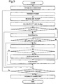
Fig. 3] Fig. 3 is a flowchart illustrating an operational procedure of the communication device according to the exemplary embodiment of the present invention. - In the following, exemplary embodiments of the present invention will be described with reference to the drawings.
- First, basic contents of a communication device according to the present invention will be described based on
Fig. 1 . - In
Fig. 1 , acommunication device 1 includes a transmissiondata output unit 11 for outputting a predetermined amount of communication data toward acounterpart communication device 2 which is a communication destination via anetwork 10 and a transmissionrate control unit 18 for controlling a data amount continuously transmittable to thenetwork 10 by drive-controlling the transmissiondata output unit 11. - In addition, the transmission
rate control unit 18 described above includes a transmissionrate control function 18A for controlling so as to keep continuously transmitting the transmission data in a range not exceeding an upper limit value of a specified transmission rate determined in advance. - Here, a
reference numeral 12 denotes a network interface unit for transmitting to and receiving from thenetwork 10 described above. Further, areference numeral 13 denotes a data receive unit for receiving transmission information from thecounterpart communication device 2 via thenetwork 10 and areference numeral 19 denotes a data transmission unit for transmitting predetermined transmission data to thecounterpart communication device 2 via thenetwork 10. - Then, in an actual data transmission, the transmission
data output unit 11 is operated by being drive-controlled by the transmissiondata output unit 11 and outputs a predetermined amount of communication data toward thecounterpart communication device 2 which is a communication destination via thenetwork 10. In this case, the transmissiondata output unit 11 is controlled so as to keep continuously transmitting the transmission data within a framework of the predetermined specific transmission rate as described above and in a range not exceeding its upper limit value. - Therefore, according to the present exemplary embodiment, it is possible to transmit data at a transmission rate suitable for a situation at the current time even if a communication line is, for example, a bottleneck line, and thereby to avoid congestion, while a band of the bottleneck line being effectively utilized, even in a communication environment in which random packet discards and packet error recovery delays occur.
- Hereinafter, the present exemplary embodiment will be described in more detail based on
Fig. 2 andFig. 3 including the basic contents ofFig. 1 described above. - In
Fig. 2 , thecommunication device 1 according to the present exemplary embodiment includes: anetwork interface unit 12 for transmitting and receiving predetermined data to and from thecounterpart communication device 2 via thenetwork 10; a data receiveunit 13 for receiving transmission data transmitted from thecounterpart communication device 2; anRTT calculation unit 14 for calculating RTT (Round Trip Time) as a transmission data response time as required; and a receiverate calculation unit 15 for calculating a receive rate of a receive side. - Furthermore, the
communication device 1 includes: a transmission rate controlmode specifying unit 16 for specifying a transmission rate control mode using a value (congestion information of a network) of RTT calculated by theRTT calculation unit 14 described above as a reference; a transmissionrate calculation unit 17 for determining an upper limit value of a transmission rate according to the specified transmission rate control mode; a transmissionrate control unit 18 for controlling an output operation of the transmissiondata output unit 11 provided in advance; and adata transmission unit 19 for outputting, toward the otherside communication unit 2 described above, transmission data outputted from the transmissiondata output unit 11 by being controlled by the transmissionrate control unit 18. - Here, the transmission
rate control unit 18 is provided with the transmission rate controlmode specifying unit 16 and the transmissionrate calculation unit 17 described above and it is configured such that the transmissionrate control unit 18 controls an output operation of the transmissiondata output unit 11 based on respective output information of the transmission rate controlmode specifying unit 16 and the transmissionrate calculation unit 17. - The
network interface unit 12 includes a function that, when a packet is received from thenetwork 10, the packet is transmitted to the data receiveunit 13. Furthermore, it includes a function that, when a packet for transmission is received from thedata transmission unit 19, the packet is transmitted to thenetwork 10. - The data receive
unit 13 described above includes a function that, when a packet is received from thenetwork interface unit 12, the packet is transmitted to each of theRTT calculation unit 14 and the receiverate calculation unit 15. - Further, the
RTT calculation unit 14 includes a function of calculating RTT as a transmission data response time by analyzing the packet received from the data receiveunit 13. For example, RTT can be calculated in a similar way as for TCP. - In other words, when Timestamp Option is available, RTT may be set to "(the current time) - (Timestamp Echo)" upon receiving ACK which is a positive response signal.
- On the other hand, when Timestamp Option is not available, RTT may be set to "(the current time) - (time when the packet responded by ACK has been transmitted)" upon receiving ACK.
- The receive
rate calculation unit 15 includes a function of calculating a receive rate of a receive side by analyzing a packet received from the data receiveunit 13. - For example, acknowledgement numbers described in i-th ACK received at a time t_i and i+k-th ACK received at a time t_i+k are set respectively to RcvBytes_i and RcvBytes_i+k.
- At this time, a receive rate RcvRate of the receive side during time t_i to time t_i+k may be approximately set to RcvRate = (RcvBytes_i+k-RcvBytes_i) / (t_i+k-t_i).
- Where, a parameter k is an arbitrary natural number which is set in advance. Further, the receive rate may be a moving average of values of RcvRate in the past in order to remove errors.
- The transmission rate control
mode specifying unit 16 includes a function of specifying as any one of the following control modes using a value of RTT calculated by theRTT calculation unit 14 as a reference. Here, in the present exemplary embodiment, three modes of a rate surge mode, a rate adjustment mode, and a rate suppression mode are set in advance as the transmission rate control modes. - Here, the rate surge mode is a mode in which the transmission rate is rapidly increased assuming that the bottleneck line band is not fully utilized.
- Besides, the rate adjustment mode is a mode in which the transmission rate is gradually increased assuming the bottleneck line band is almost fully utilized.
- Further, the rate suppression mode is a mode in which the transmission rate is suppressed assuming that the bottleneck line band is exceeded in transmission.
- Then, the transmission rate control
mode specifying unit 16 sets the minimum RTT to RTT_min and the maximum RTT to RTT_max and specifies the transmission rate control mode to the rate surge mode when the communication line is "RTT ≤ RTT_min". - In other words, the transmission rate control
mode specifying unit 16 includes a function of specifying said transmission rate control mode to the rate surge mode for rapidly increasing the transmission rate when the signal propagation time RTT at the current time becomes equal to or less than the minimum value (RTT_min) of signal propagation times in the past. - Furthermore, the transmission rate control
mode specifying unit 16 specifies the transmission rate control mode to the rate adjustment mode when the communication line is "RTT_min < RTT < RTT_max". - In other words, the transmission rate control
mode specifying unit 16 includes a function of specifying said transmission rate control mode to the rate adjustment mode for gradually increasing the transmission rate when the signal propagation time RTT at the current time is greater than the minimum value (RTT_min) and less than the maximum value (RTT_max) of signal propagation times in the past. - In addition, the transmission rate control
mode specifying unit 16 specifies the transmission rate control mode to the rate suppression mode when the communication line is "RTT_max ≤ RTT". - In other words, the transmission rate control
mode specifying unit 16 includes a function of specifying the transmission rate control mode to the rate suppression mode for suppressing the transmission rate when the signal propagation time RTT at the current time is equal to or greater than the maximum value (RTT_max) of signal propagation times in the past. - Here, RTT_min and RTT_max are determined, for example, as follows. RTT_min is a value suggesting that congestion has not occurred at that time and is set to the minimum RTT among RTT values in the past.
- And, RTT_max is a value suggesting that congestion has occurred at that time and is set to an RTT value immediately before detection of a packet discard, an RTT value immediately before detection of continuous packets, or an average value of RTT values in the vicinity thereof.
- Thus, in the present exemplary embodiment, the transmission rate control
mode specifying unit 16 described above includes a control mode specifying function for specifying respectively to the rate surge mode, the rate adjustment mode, and the rate suppression mode, which are the transmission rate control modes described above, corresponding to each case that the signal propagation time (communication time) in thenetwork 10 is short, normal, or long. - Further, the transmission
rate calculation unit 17 described above includes a function for determining the upper limit value of the transmission rate according to the transmission rate control mode specified by the transmission rate controlmode specifying unit 16. - When the transmission rate control mode is the rate surge mode, the upper limit value of the transmission rate is calculated according to "R_lim=R_lim+R_u". Where, R_u is a unit rate determined in advance.
- Further, when the transmission rate control mode is the rate adjustment mode, the upper limit value of the transmission rate is calculated according to "R_lim=R_lim+R_u" every time the rate adjustment mode consecutively continues by n times. In cases other than that, it is calculated according to "R_lim=R_lim".
- Where, the parameter n is an arbitrary natural number set in advance. In addition, for example, when a band upper limit value B_max of a specification of the bottleneck line is known, it may be calculated according to "R_lim=(1-α)×R_lim+α×B_max". Where, the parameter α is a real number in a range of 0<α<1 set in advance.
- Furthermore, when the transmission rate control mode is the rate suppression mode, the upper limit value of the transmission rate is calculated according to "R_lim=RcvRate". Where, RcvRate is a receive rate of a receive side calculated by the receive
rate calculation unit 15. - Further, the transmission
rate control unit 18 described above includes a function of transmitting data with R_lim as the upper limit which is the upper limit value of the transmission rate calculated by the transmissionrate calculation unit 17. At that time, a flow control based on a congestion window (CWND, Congestion Window) of TCP is not performed and data continues to be transmitted at the maximum transmission rate with R_lim as the upper limit as long as a receive buffer size (RWIN, Receive Window) of the receive side does not become zero. - In other words, the transmission
rate control unit 18 includes a maximum ratetransmission control function 18A of continuing a transmission control of data at the maximum transmission rate in a range not exceeding the transmission rate upper limit value as long as a free space of a buffer size of a receivebuffer 13A in the data receiveunit 13 provided in advance does not become zero. - When it is notified that the receive buffer size of the data receive
unit 13 in the receive side by ACK which is a positive response signal is zero, it means that a free space in the receivebuffer 13A of the receive side has run out. In this case, transmission is interrupted until a receive buffer size of a value greater than zero is notified from the receive side to the transmission side. - Then, the
data transmission unit 19 described above transmits packets with a timing specified by the transmissionrate control unit 18. - Next, an operational procedure of the communication device according to the exemplary embodiment described above will be described based on a flowchart of
Fig. 3 . - First, a main portion of the operational procedure leading to data transmission of the
communication device 1 in the exemplary embodiment described above will be described. - First, in the communication device described above including the transmission
data output unit 11 for outputting a predetermined amount of communication data toward the communication destination via thenetwork 10 and the transmissionrate control unit 18 for controlling a data amount continuously transmittable to thenetwork 10 by drive-controlling the transmissiondata output unit 11, the transmission rate controlmode specifying unit 16 provided in advance, specifies a transmission rate control mode required for transmitting the data based on congestion information obtained from thenetwork 10 described above (a transmission rate control mode specifying step). - Next, the transmission
rate calculation unit 15 provided in advance determines an upper limit value of a transmission rate according to a transmission rate control mode specified by the transmission rate control mode specifying unit 16 (a transmission rate upper limit value determination step). - Subsequently, said transmission
rate control unit 18 is configured to drive-control said transmissiondata output unit 11 such that the transmission data continues to be continuously transmitted in a range not exceeding the upper limit value of the specific transmission rate determined by the transmission rate calculation unit 15 (a data output control step). - Then, the object described above is achieved by configuring the operational procedures in the present exemplary embodiment as described above and executing the operational procedures in sequence.
- Hereinafter, these will be described in more detail.
- First, the communication device 1 (hereinafter, referred to as a "transmission terminal") of the transmission side establishes a TCP connection between its
own device 1 which is the transmission terminal and the counterpart communication device 2 (hereinafter, referred to as a "receive terminal") which is the receive side via the Internet 10 (Fig. 3 : step S101) and starts transmission of transmission data (Fig. 3 : step S102). - When an acknowledgement packet (an ACK packet) is returned from the receive
terminal 2 in response to a packet transmitted from thetransmission terminal 1, the data receiveunit 13 receives it (Fig. 3 : step S103). TheRTT calculation unit 14 obtains RTT received using the received ACK packet and, at the same time, the receiverate calculation unit 15 calculates a data receive rate RcvRate of the receive terminal 2 (Fig. 3 : step S104). - Thereby, a congestion state (i.e. network information to specify a transmission rate control mode required for data transmission) of the
network 10 at the current time is first detected by a value of the signal propagation time RTT. - Next, when RTT ≤ RTT_min, the transmission rate control
mode specifying unit 16 determines that the transmission rate control mode is the transmission rate surge mode (Fig. 2 : 105/ YES). - In other words, in a step of specifying the transmission rate control mode described above, when the signal propagation time RTT in the
network 10 at the current time becomes equal to or less than the minimum value (RTT_min) of signal propagation times in the past, said transmission rate controlmode specifying unit 16 specifies said transmission rate control mode as the rate surge mode for rapidly increasing said transmission rate. - In response to this result, the transmission
rate calculation unit 17 calculates the upper limit value of the transmission rate according to R_lim = R_lim+R_u (Fig. 2 : 106). - On the other hand, when RTT_min<RTT<RTT_max, the transmission rate control
mode specifying unit 16 determines the transmission rate control mode to be the rate adjustment mode (Fig. 2 : 107/YES). In other words, in a step of specifying said transmission rate control mode, when the signal propagation time RTT in saidnetwork 10 at the current time is greater than the minimum value (RTT_min) and less than the maximum value (RTT_max) of signal propagation times in the past, said transmission rate controlmode specifying unit 16 specifies said transmission rate control mode to the rate adjustment mode for gradually increasing said transmission rate. - Then, in response to this result, the transmission
rate calculation unit 17 sets X=X+1 (Fig. 2 : 108), sets X=0 when X=n (Fig. 2 : 109/YES), and sets the upper limit value of the transmission rate to R_lim = R_lim+R_u (Fig. 2 : 110). - In addition, the transmission rate control
mode specifying unit 16 determines the transmission rate control mode to be the rate suppression mode when RTT_max ≤ RTT (Fig. 2 : 107/NO). The upper limit value of the transmission rate is set to R_lim = RcvRate (Fig. 2 : 111). - In other words, in a step of specifying said transmission rate control mode, when the signal propagation time RTT in said
network 10 at the current time becomes equal to or greater than the maximum value (RTT_max) of signal propagation times in the past, said transmission rate controlmode specifying unit 16 specifies said transmission rate control mode to the rate suppression mode for suppressing said transmission rate. - Then, the
transmission terminal 1 repeats the means described above until data to be transmitted has run out (Fig. 2 : 112) and finally disconnects the TCP connection to terminate the communication (Fig. 2 : 113). - On the other hand, the transmission
rate control unit 18 does not perform a flow control based on the congestion window (CWND, Congestion Window) of TCP and continues to transmit data at the maximum transmission rate with R_lim as the upper limit as long as the buffer size (RWIN, Receive Window) of the receivebuffer 13A in the data receiveunit 13 of the receive side does not become zero. - In other words, in a step of drive-controlling the transmission
data output unit 11 described above, said transmissionrate control unit 16 is configured to continue a transmission control of said data at the maximum transmission rate in a range not exceeding the upper limit value of said transmission rate as long as a free space of the buffer size of the receivebuffer 13A in the data receiveunit 13 provided in advance does not become zero. - On the other hand, when it is notified by ACK that the receive buffer size of the receive side is zero, it means that a free space in the receive
buffer 13A of the receive side has run out. In that case, the transmission is interrupted until the receive buffer size of a value greater than zero is notified from the receive side to the transmission side (Fig. 2 : 102). - Here, in each operation step (a content execution step) described above, it may be configured such that the execution content is programmed so as to cause a computer provided in said
communication device 1 in advance to implement it. The program may be recorded in a non-temporary storage medium, for example, a DVD, a CD, a flash memory or the like. In that case, the present program is retrieved from the storage medium by the computer to be executed. - As described above, according to the present exemplary embodiment, the transmission rate is not unnecessarily decreased even when a packet discard not caused by a congestion occurrence is detected, by measuring RTT and determining a transmission rate using the RTT as a reference.
- In addition, by not performing a flow control based on the congestion window of TCP and continuing to transmit data at the maximum transmission rate with R_lim as the upper limit as long as the receive buffer size (RWIN, Receive Window) of the receive side does not become zero, the transmission rate is not unnecessarily decreased even when an increase of RTT not caused by a congestion occurrence due to an automatic retransmission control of a wireless link layer or the like is generated.
- Furthermore, by providing the rate adjustment mode in addition to the rate surge mode and the rate suppression mode as the transmission rate control modes, even if an error exists in estimating the RTT reference values (RTT_min and RTT_max), its effects can be made small. In addition, the throughput can be relatively easily improved since a mechanism for notifying special information from a network to a communication device is not required.
- As described above, the
communication device 1 according to the present exemplary embodiment is configured and functions as described above and, therefore, data can be transmitted at a transmission rate suitable for a situation at the current time even when the communication line is, for example, a bottleneck line based on a utilization rate of the bottleneck line estimated using RTT (Round Trip Time) which is a transmission data response time and, accordingly, congestion can be avoided, while a band of the bottleneck line being effectively utilized, even in a communication environment in which random packet discards and packet error recovery delays may occur. - With regards to an applicable scope of the present invention, the present invention may be applied, for example, to a relay device for relaying a session between the
communication device 1 and thecommunication device 2 connected via a network. The relay device is to relay a communication session between the two terminals by once terminating a communication session with thecommunication device 1 of one side and then establishing a new communication session with thecommunication device 2 of the other side in the communication session between the two communication devices. - Although a communication protocol suitable for implementing the present invention is TCP as described in the above exemplary embodiment, it is not limited to the TCP but may be of other communication protocol as long as it performs a congestion control.
- Now, with regards to the exemplary embodiment described above, summarized main points of new technical contents are as follows.
- Note that although, in the following, the technical contents of the above exemplary embodiment may be summarized as
Supplementary Note 1 toSupplementary Note 18 as follows, the present invention is not necessarily limited thereto. - A communication device comprising: a transmission data output unit for outputting a predetermined amount of communication data toward a communication destination via a network; and a transmission rate control unit for controlling a data amount continuously transmittable to the network by drive-controlling the transmission data output unit,
- wherein the transmission rate control unit comprises a transmission rate control function for controlling so as to keep continuously transmitting the transmission data in a range not exceeding an upper limit value of a specific transmission rate determined in advance.
- The communication device according to
Supplementary Note 1, wherein - the transmission rate control unit is provided with a transmission rate control mode specifying unit for specifying a transmission rate control mode based on congestion information of the network and a transmission rate calculation unit for determining an upper limit value of a transmission rate according to the specified transmission rate control mode and
the transmission rate control unit comprises a function of controlling an output operation of the transmission data output unit based on respective output information of the transmission rate control mode specifying unit and the transmission rate calculation unit. - The communication device according to
Supplementary Note 2, wherein
the transmission rate control mode specifying unit comprises a function of specifying the transmission rate control mode to any one of a rate surge mode for rapidly increasing the transmission rate, a rate adjustment mode for gradually increasing the transmission rate, and a rate suppression mode for suppressing the transmission rate based on congestion information of the network. - The communication device according to Supplementary Note 3, wherein
the transmission rate control mode specifying unit comprises a control mode specifying function of specifying the transmission rate control mode depending on a signal propagation time in the network is short, normal, or long. - The communication device according to
Supplementary Note 2, wherein
the transmission rate control mode specifying unit comprises a function of specifying the transmission rate control mode to a rate surge mode for rapidly increasing the transmission rate when a signal propagation time at the current time becomes equal to or less than a minimum value of signal propagation times in the past. - The communication device according to
Supplementary Note 2, wherein
the transmission rate control mode specifying unit comprises a function of specifying the transmission rate control mode to a rate adjustment mode for gradually increasing the transmission rate when a signal propagation time at the current time becomes greater than a minimum value and less than a maximum value of signal propagation times in the past. - The communication device according to
Supplementary Note 2, wherein
the transmission rate control mode specifying unit comprises a function of specifying the transmission rate control mode to a rate suppression mode for suppressing the transmission rate when a signal propagation time at the current time becomes equal to or greater than a maximum value of signal propagation times in the past. - The communication device according to
Supplementary Note 1, wherein
the transmission rate control unit comprises a maximum rate transmission control function of continuing a transmission control of data at a maximum transmission rate in a range not exceeding a transmission rate upper limit value as long as a free space of a receive buffer size of a data receive unit provided in advance does not become zero. - A transmission data output control method for
a communication device comprising: a transmission data output unit for outputting a predetermined amount of communication data toward a communication destination via a network; and a transmission rate control unit for controlling a data amount continuously transmittable to the network by drive-controlling the transmission data output unit, wherein
a transmission rate control mode specifying unit provided in advance specifies a transmission rate control mode required for transmitting the data based on congestion information obtained from the network,
a transmission rate calculation unit provided in advance determines an upper limit value of a transmission rate according to the specified transmission rate control mode, and
the transmission rate control unit drive-controls the transmission data output unit so as to keep continuously transmitting the transmission data in a range not exceeding the determined upper limit value of the transmission rate. - The transmission data output control method according to Supplementary Note 9, wherein
in a step of specifying the transmission rate control mode, the transmission rate control mode specifying unit specifies the transmission rate control mode to a rate surge mode for rapidly increasing the transmission rate when a signal propagation time in the network at the current time becomes equal to or less than a minimum value of signal propagation times in the past. - The transmission data output control method according to Supplementary Note 9, wherein
in a step of specifying the transmission rate control mode, the transmission rate control mode specifying unit specifies the transmission rate control mode to a rate adjustment mode for gradually increasing the transmission rate when a signal propagation time in the network at the current time becomes greater than a minimum value and less than a maximum value of signal propagation times in the past. - The transmission data output control method according to Supplementary Note 9, wherein
in a step of specifying the transmission rate control mode, the transmission rate control mode specifying unit specifies the transmission rate control mode to a rate suppression mode for suppressing the transmission rate when a signal propagation time in the network at the current time becomes equal to or greater than a maximum value of signal propagation times in the past. - The transmission data output control method according to Supplementary Note 9, wherein
in a step of drive-controlling the transmission data output unit, the transmission data control unit is configured to continue a transmission control of the data at a maximum transmission rate in a range not exceeding an upper limit value of the transmission rate as long as a free space of a receive buffer size of a data receive unit provided in advance does not become zero. - (Supplementary Note 14) (Program Invention/ Corresponding to Supplementary Note 9)
- A transmission data output control program for
a communication device comprising: a transmission data output unit for outputting a predetermined amount of communication data toward a communication destination via a network; and a transmission rate control unit for controlling a data amount continuously transmittable to the network by drive-controlling the transmission data output unit, wherein
a computer is caused to realize functions provided, the functions comprising: - a rate control mode specifying function for specifying a transmission rate control mode required for transmitting the data based on congestion information of the network;
- a transmission rate upper limit value determination function for determining an upper limit value of a transmission rate according to the specified transmission rate control mode; and
- an output unit drive-control function for drive-controlling the transmission data output unit so as to keep continuously transmitting the transmission data in a range not exceeding the determined upper limit value of the specified transmission rate.
- The transmission data output control program according to
Supplementary Note 14, wherein
the rate control mode specifying function for specifying the transmission rate control mode is configured to comprise a function for specifying the transmission rate control mode to a rate surge mode for rapidly increasing the transmission rate when a signal propagation time in the network at the current time becomes equal to or less than a minimum value of signal propagation times in the past and
the computer is caused to realize the specifying process function. - The transmission data output control program according to
Supplementary Note 14, wherein
the rate control mode specifying function for specifying the transmission rate control mode is configured to comprise a function for specifying the transmission rate control mode to a rate adjustment mode for gradually increasing the transmission rate when a signal propagation time in the network at the current time becomes greater than a minimum value and less than a maximum value of signal propagation times in the past and
the computer is caused to realize the specifying process function. - The transmission data output control program, wherein
the rate control mode specifying function for specifying the transmission rate control mode is configured to comprise a function for specifying the transmission rate control mode to a rate suppression mode for suppressing the transmission rate when a signal propagation time in the network at the current time becomes equal to or greater than a maximum value of signal propagation times in the past and
the computer is caused to realize the specifying process function. - The transmission data output control program according to
Supplementary Note 14, wherein
the output unit drive-control function for drive-controlling the transmission data output unit is configured to comprise a function for continuing a transmission control of the transmission data at a maximum transmission rate in a range not exceeding an upper limit value of a transmission rate as long as a free space of a receive buffer size of a data receive unit provided in advance does not become zero and
the computer is caused to realize the control function. - This application is based upon and claims the benefit of priority from Japanese patent application No.
2012-243363, filed on November 5, 2012 - The present invention may be applied to a communication terminal, a communication relay device, a communication server device, respective systems relating to a wired communication and a wireless communication, and the like.
-
- 1
- communication device
- 2
- counterpart communication device
- 10
- network
- 11
- transmission data output unit
- 12
- network interface unit
- 13
- data receive unit
- 13A
- receive buffer
- 14
- RTT calculation unit
- 15
- receive rate calculation unit
- 16
- transmission rate control mode specifying unit
- 17
- transmission rate calculation unit
- 18
- transmission rate control unit
- 18A
- maximum rate transmission control function
- 19
- data transmission unit
Claims (8)
- A communication device comprising: a transmission data output unit (11) for outputting a predetermined amount of communication data toward a communication destination via a network (10); and a transmission rate control unit (18) for controlling a data amount continuously transmittable to the network by drive-controlling the transmission data output unit (11),
wherein the transmission rate control unit (18) comprises a transmission rate control function for controlling so as to keep continuously transmitting the transmission data in a range not exceeding an upper limit value of a specific transmission rate determined in advance,
the transmission rate control unit (18) is provided with a transmission rate control mode specifying unit (16) for specifying a transmission rate control mode based on congestion information of the network (18) and a transmission rate calculation unit (17) for determining an upper limit value of a transmission rate according to the specified transmission rate control mode and
the transmission rate control unit (18) comprises a function of controlling an output operation of the transmission data output unit (11) based on respective output information of the transmission rate control mode specifying unit (16) and the transmission rate calculation unit (17),
characterized in that the transmission rate control mode specifying unit (16) comprises a function of specifying the transmission rate control mode to any one of a rate surge mode for rapidly increasing the transmission rate, a rate adjustment mode for gradually increasing the transmission rate, and a rate suppression mode for suppressing the transmission rate based on congestion information of the network (10). - The communication device according to claim 1, wherein
the transmission rate control mode specifying unit (16) comprises a control mode specifying function of specifying the transmission rate control mode depending on a signal propagation time in the network (10) is short, normal, or long. - The communication device according to claim 1, wherein
the transmission rate control mode specifying unit (16) comprises the function of specifying the transmission rate control mode to the rate surge mode for rapidly increasing the transmission rate when a signal propagation time at the current time becomes equal to or less than a minimum value of signal propagation times in the past. - The communication device according to claim 1, wherein
the transmission rate control mode specifying unit (16) comprises the function of specifying the transmission rate control mode to the rate adjustment mode for gradually increasing the transmission rate when a signal propagation time at the current time becomes greater than a minimum value and less than a maximum value of signal propagation times in the past. - The communication device according to claim 1, wherein
the transmission rate control mode specifying unit (16) comprises the function of specifying the transmission rate control mode to the rate suppression mode for suppressing the transmission rate when a signal propagation time at the current time becomes equal to or greater than a maximum value of signal propagation times in the past. - The communication device according to claim 1, wherein
the transmission rate control unit (18) comprises a maximum rate transmission control function of continuing a transmission control of data at a maximum transmission rate in a range not exceeding a transmission rate upper limit value as long as a free space of a receive buffer size of a data receive unit provided in advance does not become zero. - A transmission data output control method for
a communication device comprising: a transmission data output unit (11) for outputting a predetermined amount of communication data toward a communication destination via a network (10); and a transmission rate control unit (18) for controlling a data amount continuously transmittable to the network by drive-controlling the transmission data output unit (11), wherein
a transmission rate control mode specifying unit (16) provided in advance specifies a transmission rate control mode required for transmitting the data based on congestion information obtained from the network (10) to any one of a rate surge mode for rapidly increasing the transmission rate, a rate adjustment mode for gradually increasing the transmission rate, and a rate suppression mode for suppressing the transmission rate based on congestion information of the network (10),
a transmission rate calculation unit (17) provided in advance determines an upper limit value of a transmission rate according to the specified transmission rate control mode, and
the transmission rate control unit (18) drive-controls the transmission data output unit (11) so as to keep continuously transmitting the transmission data in a range not exceeding the determined upper limit value of the specified transmission rate. - A transmission data output control program for a communication device comprising: a transmission data output unit (11) for outputting a predetermined amount of communication data toward a communication destination via a network (10); and a transmission rate control unit (18) for controlling a data amount continuously transmittable to the network (10) by drive-controlling the transmission data output unit (11), wherein
a computer is caused to realize functions provided, the functions comprising:a rate control mode specifying function for specifying a transmission rate control mode required for data transmission based on congestion information of the network (10) to any one of a rate surge mode for rapidly increasing the transmission rate, a rate adjustment mode for gradually increasing the transmission rate, and a rate suppression mode for suppressing the transmission rate based on congestion information of the network (10);a transmission rate upper limit value determination function for determining an upper limit value of a transmission rate according to the specified transmission rate control mode; andan output unit drive-control function for drive-controlling the transmission data output unit so as to keep continuously transmitting the transmission data in a range not exceeding the determined upper limit value of the specified transmission rate.
Applications Claiming Priority (2)
| Application Number | Priority Date | Filing Date | Title |
|---|---|---|---|
| JP2012243363 | 2012-11-05 | ||
| PCT/JP2013/079785 WO2014069642A1 (en) | 2012-11-05 | 2013-11-01 | Communication device, transmission data output control method, and program for same |
Publications (3)
| Publication Number | Publication Date |
|---|---|
| EP2916521A1 EP2916521A1 (en) | 2015-09-09 |
| EP2916521A4 EP2916521A4 (en) | 2016-06-29 |
| EP2916521B1 true EP2916521B1 (en) | 2018-02-21 |
Family
ID=50627534
Family Applications (1)
| Application Number | Title | Priority Date | Filing Date |
|---|---|---|---|
| EP13850413.9A Not-in-force EP2916521B1 (en) | 2012-11-05 | 2013-11-01 | Communication device, transmission data output control method, and program for same |
Country Status (4)
| Country | Link |
|---|---|
| US (1) | US9674101B2 (en) |
| EP (1) | EP2916521B1 (en) |
| JP (1) | JPWO2014069642A1 (en) |
| WO (1) | WO2014069642A1 (en) |
Families Citing this family (9)
| Publication number | Priority date | Publication date | Assignee | Title |
|---|---|---|---|---|
| US9992120B2 (en) * | 2015-10-21 | 2018-06-05 | Citrix Systems, Inc. | System and method for rate-based packet transmission over a network |
| MX2018013846A (en) * | 2016-07-01 | 2019-03-21 | Ericsson Telefon Ab L M | Round trip time skew control methods and arrangements. |
| JP6983883B2 (en) * | 2016-11-03 | 2021-12-17 | パナソニック インテレクチュアル プロパティ コーポレーション オブ アメリカPanasonic Intellectual Property Corporation of America | Wireless communication methods, devices, and systems |
| US10567300B2 (en) * | 2017-11-22 | 2020-02-18 | Cisco Technology, Inc. | Layer 3 fair rate congestion control notification |
| JP7043808B2 (en) | 2017-11-30 | 2022-03-30 | 富士通株式会社 | Communication equipment, communication system, and communication speed control method |
| CN108494698B (en) * | 2017-12-13 | 2022-02-25 | 天地伟业技术有限公司 | Congestion control method based on transmission rate |
| US11296988B2 (en) | 2019-11-14 | 2022-04-05 | Mellanox Technologies, Ltd. | Programmable congestion control communication scheme |
| US11218413B2 (en) * | 2019-11-14 | 2022-01-04 | Mellanox Technologies, Ltd. | Congestion control management method derived from packets at a network adapter |
| CN114070794A (en) * | 2020-08-06 | 2022-02-18 | 迈络思科技有限公司 | Programmable congestion control communication scheme |
Family Cites Families (16)
| Publication number | Priority date | Publication date | Assignee | Title |
|---|---|---|---|---|
| JP4101993B2 (en) | 1999-12-03 | 2008-06-18 | 三菱電機株式会社 | Wired and wireless mixed network data distribution apparatus and wired and wireless mixed network data distribution method |
| US20020075895A1 (en) * | 2000-10-27 | 2002-06-20 | Takao Yamaguchi | Transmission rate controller and transmission rate control method |
| JP4351418B2 (en) | 2002-04-26 | 2009-10-28 | 株式会社エヌ・ティ・ティ・ドコモ | Multimedia streaming transmission rate control method and apparatus |
| JP3665309B2 (en) | 2002-08-19 | 2005-06-29 | 株式会社国際電気通信基礎技術研究所 | COMMUNICATION SYSTEM, COMMUNICATION DEVICE, AND COMMUNICATION METHOD |
| KR100526187B1 (en) * | 2003-10-18 | 2005-11-03 | 삼성전자주식회사 | Method of obtaining the optimum rate control in mobile ad hoc network circumstance |
| JP4362761B2 (en) | 2003-10-29 | 2009-11-11 | ソニー株式会社 | Transmission device and method, recording medium, and program |
| US8125910B2 (en) * | 2004-06-25 | 2012-02-28 | Nec Corporation | Communication system |
| JP4147534B2 (en) | 2005-02-03 | 2008-09-10 | 日本電気株式会社 | Communication apparatus and communication method |
| JP4643330B2 (en) * | 2005-03-28 | 2011-03-02 | ソニー株式会社 | COMMUNICATION PROCESSING DEVICE, DATA COMMUNICATION SYSTEM, COMMUNICATION PROCESSING METHOD, AND COMPUTER PROGRAM |
| JP4407700B2 (en) * | 2007-02-02 | 2010-02-03 | 日本電気株式会社 | Communication terminal, communication system, congestion control method, and congestion control program |
| JP2012515491A (en) * | 2009-01-16 | 2012-07-05 | メインライン ネット ホールディングス リミテッド | Maximize bandwidth utilization in networks with packet loss and high latency using transmission control protocols |
| JP5652388B2 (en) * | 2009-03-06 | 2015-01-14 | 日本電気株式会社 | COMMUNICATION RATE CONTROL METHOD, TRANSMITTER, AND COMMUNICATION SYSTEM |
| JP5375416B2 (en) * | 2009-08-03 | 2013-12-25 | 日本電気株式会社 | Stream delivery apparatus, stream delivery system, stream delivery method, and stream delivery program |
| WO2011074681A1 (en) * | 2009-12-14 | 2011-06-23 | 日本電気株式会社 | Communication apparatus and communication control method |
| US9444688B2 (en) * | 2011-10-04 | 2016-09-13 | North Carolina State University | Receiver-based methods, systems, and computer readable media for controlling TCP sender behavior in mobile communications networks with large buffer sizes |
| US8923270B2 (en) * | 2011-10-04 | 2014-12-30 | The Chinese University Of Hong Kong | Method for link buffer size and queue length estimation for bandwidth-varying mobile data networks |
-
2013
- 2013-11-01 EP EP13850413.9A patent/EP2916521B1/en not_active Not-in-force
- 2013-11-01 WO PCT/JP2013/079785 patent/WO2014069642A1/en active Application Filing
- 2013-11-01 JP JP2014544614A patent/JPWO2014069642A1/en active Pending
- 2013-11-01 US US14/440,003 patent/US9674101B2/en not_active Expired - Fee Related
Non-Patent Citations (1)
| Title |
|---|
| None * |
Also Published As
| Publication number | Publication date |
|---|---|
| JPWO2014069642A1 (en) | 2016-09-08 |
| EP2916521A1 (en) | 2015-09-09 |
| EP2916521A4 (en) | 2016-06-29 |
| US9674101B2 (en) | 2017-06-06 |
| WO2014069642A1 (en) | 2014-05-08 |
| US20150304226A1 (en) | 2015-10-22 |
Similar Documents
| Publication | Publication Date | Title |
|---|---|---|
| EP2916521B1 (en) | Communication device, transmission data output control method, and program for same | |
| JP4147534B2 (en) | Communication apparatus and communication method | |
| JP4708978B2 (en) | Communication system, communication terminal, session relay device, and communication protocol realizing high throughput | |
| US9641650B2 (en) | TCP proxy server | |
| CN105264843B (en) | Managing pending acknowledgement packets in a communication device | |
| JP5625748B2 (en) | COMMUNICATION DEVICE, COMMUNICATION SYSTEM, PROGRAM, AND COMMUNICATION METHOD | |
| JP5867188B2 (en) | Information processing apparatus, congestion control method, and congestion control program | |
| EP2938032B1 (en) | Data transmission device, data transmission method, and program therefor | |
| US9515939B2 (en) | Apparatus and method for controlling a window size of packet transmission based on a free space of buffer | |
| KR101741003B1 (en) | Method for communication using duplicated ack | |
| US8279756B2 (en) | Communication terminal, communication control method, and communication control program | |
| CN108432287A (en) | A kind of data transmission method and network side equipment | |
| JP2008053888A (en) | Communication equipment, program, information storage medium and communication control method | |
| JP6217424B2 (en) | Control apparatus and control method | |
| JP6011813B2 (en) | COMMUNICATION DEVICE AND ITS COMMUNICATION CONTROL METHOD | |
| JP5748615B2 (en) | Communication device | |
| WO2019146563A1 (en) | Communication device, communication system, communication method, and program | |
| KR100915996B1 (en) | Method and Terminal for Controlling Transmission according Bandwidth Change | |
| WO2013011638A1 (en) | Communication device and communication control method thereof | |
| WO2016147650A1 (en) | Transmitting apparatus and control method therefor, communication system, and recording medium storing communication control program | |
| JP2017158047A (en) | Relay device, relay method and relay program |
Legal Events
| Date | Code | Title | Description |
|---|---|---|---|
| PUAI | Public reference made under article 153(3) epc to a published international application that has entered the european phase |
Free format text: ORIGINAL CODE: 0009012 |
|
| 17P | Request for examination filed |
Effective date: 20150523 |
|
| AK | Designated contracting states |
Kind code of ref document: A1 Designated state(s): AL AT BE BG CH CY CZ DE DK EE ES FI FR GB GR HR HU IE IS IT LI LT LU LV MC MK MT NL NO PL PT RO RS SE SI SK SM TR |
|
| AX | Request for extension of the european patent |
Extension state: BA ME |
|
| DAX | Request for extension of the european patent (deleted) | ||
| RA4 | Supplementary search report drawn up and despatched (corrected) |
Effective date: 20160601 |
|
| RIC1 | Information provided on ipc code assigned before grant |
Ipc: H04W 28/10 20090101ALI20160525BHEP Ipc: H04L 29/08 20060101AFI20160525BHEP Ipc: H04L 12/825 20130101ALI20160525BHEP Ipc: H04W 80/06 20090101ALI20160525BHEP Ipc: H04L 12/841 20130101ALI20160525BHEP |
|
| GRAP | Despatch of communication of intention to grant a patent |
Free format text: ORIGINAL CODE: EPIDOSNIGR1 |
|
| RIC1 | Information provided on ipc code assigned before grant |
Ipc: H04W 80/06 20090101ALI20170523BHEP Ipc: H04W 28/10 20090101ALI20170523BHEP Ipc: H04L 29/08 20060101AFI20170523BHEP Ipc: H04L 12/825 20130101ALI20170523BHEP Ipc: H04L 12/841 20130101ALI20170523BHEP |
|
| INTG | Intention to grant announced |
Effective date: 20170622 |
|
| GRAS | Grant fee paid |
Free format text: ORIGINAL CODE: EPIDOSNIGR3 |
|
| GRAJ | Information related to disapproval of communication of intention to grant by the applicant or resumption of examination proceedings by the epo deleted |
Free format text: ORIGINAL CODE: EPIDOSDIGR1 |
|
| GRAL | Information related to payment of fee for publishing/printing deleted |
Free format text: ORIGINAL CODE: EPIDOSDIGR3 |
|
| INTC | Intention to grant announced (deleted) | ||
| GRAP | Despatch of communication of intention to grant a patent |
Free format text: ORIGINAL CODE: EPIDOSNIGR1 |
|
| INTG | Intention to grant announced |
Effective date: 20171130 |
|
| GRAA | (expected) grant |
Free format text: ORIGINAL CODE: 0009210 |
|
| AK | Designated contracting states |
Kind code of ref document: B1 Designated state(s): AL AT BE BG CH CY CZ DE DK EE ES FI FR GB GR HR HU IE IS IT LI LT LU LV MC MK MT NL NO PL PT RO RS SE SI SK SM TR |
|
| REG | Reference to a national code |
Ref country code: GB Ref legal event code: FG4D |
|
| REG | Reference to a national code |
Ref country code: CH Ref legal event code: EP |
|
| REG | Reference to a national code |
Ref country code: AT Ref legal event code: REF Ref document number: 972904 Country of ref document: AT Kind code of ref document: T Effective date: 20180315 |
|
| REG | Reference to a national code |
Ref country code: IE Ref legal event code: FG4D |
|
| REG | Reference to a national code |
Ref country code: DE Ref legal event code: R096 Ref document number: 602013033511 Country of ref document: DE |
|
| REG | Reference to a national code |
Ref country code: NL Ref legal event code: MP Effective date: 20180221 |
|
| REG | Reference to a national code |
Ref country code: LT Ref legal event code: MG4D |
|
| REG | Reference to a national code |
Ref country code: AT Ref legal event code: MK05 Ref document number: 972904 Country of ref document: AT Kind code of ref document: T Effective date: 20180221 |
|
| PG25 | Lapsed in a contracting state [announced via postgrant information from national office to epo] |
Ref country code: NO Free format text: LAPSE BECAUSE OF FAILURE TO SUBMIT A TRANSLATION OF THE DESCRIPTION OR TO PAY THE FEE WITHIN THE PRESCRIBED TIME-LIMIT Effective date: 20180521 Ref country code: FI Free format text: LAPSE BECAUSE OF FAILURE TO SUBMIT A TRANSLATION OF THE DESCRIPTION OR TO PAY THE FEE WITHIN THE PRESCRIBED TIME-LIMIT Effective date: 20180221 Ref country code: NL Free format text: LAPSE BECAUSE OF FAILURE TO SUBMIT A TRANSLATION OF THE DESCRIPTION OR TO PAY THE FEE WITHIN THE PRESCRIBED TIME-LIMIT Effective date: 20180221 Ref country code: CY Free format text: LAPSE BECAUSE OF FAILURE TO SUBMIT A TRANSLATION OF THE DESCRIPTION OR TO PAY THE FEE WITHIN THE PRESCRIBED TIME-LIMIT Effective date: 20180221 Ref country code: LT Free format text: LAPSE BECAUSE OF FAILURE TO SUBMIT A TRANSLATION OF THE DESCRIPTION OR TO PAY THE FEE WITHIN THE PRESCRIBED TIME-LIMIT Effective date: 20180221 Ref country code: HR Free format text: LAPSE BECAUSE OF FAILURE TO SUBMIT A TRANSLATION OF THE DESCRIPTION OR TO PAY THE FEE WITHIN THE PRESCRIBED TIME-LIMIT Effective date: 20180221 Ref country code: ES Free format text: LAPSE BECAUSE OF FAILURE TO SUBMIT A TRANSLATION OF THE DESCRIPTION OR TO PAY THE FEE WITHIN THE PRESCRIBED TIME-LIMIT Effective date: 20180221 |
|
| PG25 | Lapsed in a contracting state [announced via postgrant information from national office to epo] |
Ref country code: BG Free format text: LAPSE BECAUSE OF FAILURE TO SUBMIT A TRANSLATION OF THE DESCRIPTION OR TO PAY THE FEE WITHIN THE PRESCRIBED TIME-LIMIT Effective date: 20180521 Ref country code: GR Free format text: LAPSE BECAUSE OF FAILURE TO SUBMIT A TRANSLATION OF THE DESCRIPTION OR TO PAY THE FEE WITHIN THE PRESCRIBED TIME-LIMIT Effective date: 20180522 Ref country code: RS Free format text: LAPSE BECAUSE OF FAILURE TO SUBMIT A TRANSLATION OF THE DESCRIPTION OR TO PAY THE FEE WITHIN THE PRESCRIBED TIME-LIMIT Effective date: 20180221 Ref country code: AT Free format text: LAPSE BECAUSE OF FAILURE TO SUBMIT A TRANSLATION OF THE DESCRIPTION OR TO PAY THE FEE WITHIN THE PRESCRIBED TIME-LIMIT Effective date: 20180221 Ref country code: SE Free format text: LAPSE BECAUSE OF FAILURE TO SUBMIT A TRANSLATION OF THE DESCRIPTION OR TO PAY THE FEE WITHIN THE PRESCRIBED TIME-LIMIT Effective date: 20180221 Ref country code: LV Free format text: LAPSE BECAUSE OF FAILURE TO SUBMIT A TRANSLATION OF THE DESCRIPTION OR TO PAY THE FEE WITHIN THE PRESCRIBED TIME-LIMIT Effective date: 20180221 |
|
| PG25 | Lapsed in a contracting state [announced via postgrant information from national office to epo] |
Ref country code: EE Free format text: LAPSE BECAUSE OF FAILURE TO SUBMIT A TRANSLATION OF THE DESCRIPTION OR TO PAY THE FEE WITHIN THE PRESCRIBED TIME-LIMIT Effective date: 20180221 Ref country code: PL Free format text: LAPSE BECAUSE OF FAILURE TO SUBMIT A TRANSLATION OF THE DESCRIPTION OR TO PAY THE FEE WITHIN THE PRESCRIBED TIME-LIMIT Effective date: 20180221 Ref country code: RO Free format text: LAPSE BECAUSE OF FAILURE TO SUBMIT A TRANSLATION OF THE DESCRIPTION OR TO PAY THE FEE WITHIN THE PRESCRIBED TIME-LIMIT Effective date: 20180221 Ref country code: IT Free format text: LAPSE BECAUSE OF FAILURE TO SUBMIT A TRANSLATION OF THE DESCRIPTION OR TO PAY THE FEE WITHIN THE PRESCRIBED TIME-LIMIT Effective date: 20180221 Ref country code: AL Free format text: LAPSE BECAUSE OF FAILURE TO SUBMIT A TRANSLATION OF THE DESCRIPTION OR TO PAY THE FEE WITHIN THE PRESCRIBED TIME-LIMIT Effective date: 20180221 |
|
| REG | Reference to a national code |
Ref country code: DE Ref legal event code: R097 Ref document number: 602013033511 Country of ref document: DE |
|
| PG25 | Lapsed in a contracting state [announced via postgrant information from national office to epo] |
Ref country code: DK Free format text: LAPSE BECAUSE OF FAILURE TO SUBMIT A TRANSLATION OF THE DESCRIPTION OR TO PAY THE FEE WITHIN THE PRESCRIBED TIME-LIMIT Effective date: 20180221 Ref country code: SK Free format text: LAPSE BECAUSE OF FAILURE TO SUBMIT A TRANSLATION OF THE DESCRIPTION OR TO PAY THE FEE WITHIN THE PRESCRIBED TIME-LIMIT Effective date: 20180221 Ref country code: SM Free format text: LAPSE BECAUSE OF FAILURE TO SUBMIT A TRANSLATION OF THE DESCRIPTION OR TO PAY THE FEE WITHIN THE PRESCRIBED TIME-LIMIT Effective date: 20180221 Ref country code: CZ Free format text: LAPSE BECAUSE OF FAILURE TO SUBMIT A TRANSLATION OF THE DESCRIPTION OR TO PAY THE FEE WITHIN THE PRESCRIBED TIME-LIMIT Effective date: 20180221 |
|
| PLBE | No opposition filed within time limit |
Free format text: ORIGINAL CODE: 0009261 |
|
| STAA | Information on the status of an ep patent application or granted ep patent |
Free format text: STATUS: NO OPPOSITION FILED WITHIN TIME LIMIT |
|
| 26N | No opposition filed |
Effective date: 20181122 |
|
| PG25 | Lapsed in a contracting state [announced via postgrant information from national office to epo] |
Ref country code: SI Free format text: LAPSE BECAUSE OF FAILURE TO SUBMIT A TRANSLATION OF THE DESCRIPTION OR TO PAY THE FEE WITHIN THE PRESCRIBED TIME-LIMIT Effective date: 20180221 |
|
| REG | Reference to a national code |
Ref country code: CH Ref legal event code: PL |
|
| GBPC | Gb: european patent ceased through non-payment of renewal fee |
Effective date: 20181101 |
|
| PG25 | Lapsed in a contracting state [announced via postgrant information from national office to epo] |
Ref country code: LU Free format text: LAPSE BECAUSE OF NON-PAYMENT OF DUE FEES Effective date: 20181101 Ref country code: MC Free format text: LAPSE BECAUSE OF FAILURE TO SUBMIT A TRANSLATION OF THE DESCRIPTION OR TO PAY THE FEE WITHIN THE PRESCRIBED TIME-LIMIT Effective date: 20180221 |
|
| REG | Reference to a national code |
Ref country code: BE Ref legal event code: MM Effective date: 20181130 |
|
| REG | Reference to a national code |
Ref country code: IE Ref legal event code: MM4A |
|
| PG25 | Lapsed in a contracting state [announced via postgrant information from national office to epo] |
Ref country code: CH Free format text: LAPSE BECAUSE OF NON-PAYMENT OF DUE FEES Effective date: 20181130 Ref country code: LI Free format text: LAPSE BECAUSE OF NON-PAYMENT OF DUE FEES Effective date: 20181130 |
|
| PG25 | Lapsed in a contracting state [announced via postgrant information from national office to epo] |
Ref country code: IE Free format text: LAPSE BECAUSE OF NON-PAYMENT OF DUE FEES Effective date: 20181101 Ref country code: FR Free format text: LAPSE BECAUSE OF NON-PAYMENT OF DUE FEES Effective date: 20181130 |
|
| PG25 | Lapsed in a contracting state [announced via postgrant information from national office to epo] |
Ref country code: BE Free format text: LAPSE BECAUSE OF NON-PAYMENT OF DUE FEES Effective date: 20181130 |
|
| PG25 | Lapsed in a contracting state [announced via postgrant information from national office to epo] |
Ref country code: GB Free format text: LAPSE BECAUSE OF NON-PAYMENT OF DUE FEES Effective date: 20181101 |
|
| PG25 | Lapsed in a contracting state [announced via postgrant information from national office to epo] |
Ref country code: MT Free format text: LAPSE BECAUSE OF NON-PAYMENT OF DUE FEES Effective date: 20181101 |
|
| PGFP | Annual fee paid to national office [announced via postgrant information from national office to epo] |
Ref country code: DE Payment date: 20191022 Year of fee payment: 7 |
|
| PG25 | Lapsed in a contracting state [announced via postgrant information from national office to epo] |
Ref country code: TR Free format text: LAPSE BECAUSE OF FAILURE TO SUBMIT A TRANSLATION OF THE DESCRIPTION OR TO PAY THE FEE WITHIN THE PRESCRIBED TIME-LIMIT Effective date: 20180221 |
|
| PG25 | Lapsed in a contracting state [announced via postgrant information from national office to epo] |
Ref country code: PT Free format text: LAPSE BECAUSE OF FAILURE TO SUBMIT A TRANSLATION OF THE DESCRIPTION OR TO PAY THE FEE WITHIN THE PRESCRIBED TIME-LIMIT Effective date: 20180221 |
|
| PG25 | Lapsed in a contracting state [announced via postgrant information from national office to epo] |
Ref country code: MK Free format text: LAPSE BECAUSE OF NON-PAYMENT OF DUE FEES Effective date: 20180221 Ref country code: HU Free format text: LAPSE BECAUSE OF FAILURE TO SUBMIT A TRANSLATION OF THE DESCRIPTION OR TO PAY THE FEE WITHIN THE PRESCRIBED TIME-LIMIT; INVALID AB INITIO Effective date: 20131101 |
|
| PG25 | Lapsed in a contracting state [announced via postgrant information from national office to epo] |
Ref country code: IS Free format text: LAPSE BECAUSE OF FAILURE TO SUBMIT A TRANSLATION OF THE DESCRIPTION OR TO PAY THE FEE WITHIN THE PRESCRIBED TIME-LIMIT Effective date: 20180621 |
|
| REG | Reference to a national code |
Ref country code: DE Ref legal event code: R119 Ref document number: 602013033511 Country of ref document: DE |
|
| PG25 | Lapsed in a contracting state [announced via postgrant information from national office to epo] |
Ref country code: DE Free format text: LAPSE BECAUSE OF NON-PAYMENT OF DUE FEES Effective date: 20210601 |