EP2915696A1 - Entfernbarer Universalgurtaufroller für Fahrzeug - Google Patents
Entfernbarer Universalgurtaufroller für Fahrzeug Download PDFInfo
- Publication number
- EP2915696A1 EP2915696A1 EP15154352.7A EP15154352A EP2915696A1 EP 2915696 A1 EP2915696 A1 EP 2915696A1 EP 15154352 A EP15154352 A EP 15154352A EP 2915696 A1 EP2915696 A1 EP 2915696A1
- Authority
- EP
- European Patent Office
- Prior art keywords
- support
- jaw
- strap
- bolt
- vehicle
- Prior art date
- Legal status (The legal status is an assumption and is not a legal conclusion. Google has not performed a legal analysis and makes no representation as to the accuracy of the status listed.)
- Granted
Links
- 238000006073 displacement reaction Methods 0.000 claims abstract description 4
- 230000001681 protective effect Effects 0.000 claims description 6
- 239000000463 material Substances 0.000 description 5
- 230000015556 catabolic process Effects 0.000 description 3
- 238000006731 degradation reaction Methods 0.000 description 3
- 244000245420 ail Species 0.000 description 2
- 239000000835 fiber Substances 0.000 description 2
- 239000004753 textile Substances 0.000 description 2
- 206010001488 Aggression Diseases 0.000 description 1
- 241001415961 Gaviidae Species 0.000 description 1
- 239000004677 Nylon Substances 0.000 description 1
- 239000004952 Polyamide Substances 0.000 description 1
- 241000612118 Samolus valerandi Species 0.000 description 1
- 240000008042 Zea mays Species 0.000 description 1
- 230000006978 adaptation Effects 0.000 description 1
- 230000016571 aggressive behavior Effects 0.000 description 1
- 239000000470 constituent Substances 0.000 description 1
- 238000010586 diagram Methods 0.000 description 1
- 238000005553 drilling Methods 0.000 description 1
- 239000004744 fabric Substances 0.000 description 1
- 229920002457 flexible plastic Polymers 0.000 description 1
- 238000003780 insertion Methods 0.000 description 1
- 230000037431 insertion Effects 0.000 description 1
- 239000002184 metal Substances 0.000 description 1
- 239000004745 nonwoven fabric Substances 0.000 description 1
- 229920001778 nylon Polymers 0.000 description 1
- 239000004033 plastic Substances 0.000 description 1
- 229920003023 plastic Polymers 0.000 description 1
- 229920002647 polyamide Polymers 0.000 description 1
- 229920000728 polyester Polymers 0.000 description 1
- 239000005060 rubber Substances 0.000 description 1
- 229910001220 stainless steel Inorganic materials 0.000 description 1
- 239000010935 stainless steel Substances 0.000 description 1
- 229920001169 thermoplastic Polymers 0.000 description 1
- 239000004416 thermosoftening plastic Substances 0.000 description 1
Images


Classifications
-
- B—PERFORMING OPERATIONS; TRANSPORTING
- B60—VEHICLES IN GENERAL
- B60P—VEHICLES ADAPTED FOR LOAD TRANSPORTATION OR TO TRANSPORT, TO CARRY, OR TO COMPRISE SPECIAL LOADS OR OBJECTS
- B60P7/00—Securing or covering of load on vehicles
- B60P7/06—Securing of load
- B60P7/08—Securing to the vehicle floor or sides
- B60P7/0823—Straps; Tighteners
- B60P7/083—Tensioning by repetetive movement of an actuating member
-
- B—PERFORMING OPERATIONS; TRANSPORTING
- B60—VEHICLES IN GENERAL
- B60P—VEHICLES ADAPTED FOR LOAD TRANSPORTATION OR TO TRANSPORT, TO CARRY, OR TO COMPRISE SPECIAL LOADS OR OBJECTS
- B60P7/00—Securing or covering of load on vehicles
- B60P7/06—Securing of load
- B60P7/08—Securing to the vehicle floor or sides
- B60P7/0823—Straps; Tighteners
Definitions
- the present invention relates to a device for attaching objects to chassis structures, and relates more particularly to a device for securing objects placed outside a vehicle during transport.
- the present invention relates to a removable lashing device and adaptable according to the dimensions of the support to which it is attached.
- roof rack which is a structure, usually metal, consisting of an intercrossing of bars fixed to the vehicle, and forming a loading platform on which the loads are attached, for example, using tensioners, straps or bungees.
- the longitudinal bar consists of two bars connected by transverse tubes (see Figure 1A ) or consists of a single larger piece with no cross tubes (see Figure 1B ).
- longitudinal bars may vary depending on the design and / or manufacturer of the roof rack.
- the longitudinal bars may have a round, square, rectangular or oval section.
- the patent US 6,322,279 proposes a fixing device which is adjustable.
- This device makes it possible to attach accessories, such as a bicycle, skis, or a transport gallery, to a frame, such as the roof rack of a car. It comprises an upper part with a notch to accommodate the accessory and a lower part provided with a strap for fixing the device to the roof bar.
- This device is adjustable for roof bars of circular, oval and rectangular shape thanks to a cavity located in the lower part of the device. This However, the fit is limited to the dimensions and shapes of the cavity that can accommodate rectangular or round bars with fixed dimension recesses.
- This device also has the disadvantage that it does not allow the attachment of any type of load but only accessories that can slip into the grooved portion.
- the patent US 4,900,203 proposes a load securing system on a pick-up type vehicle, which itself can accommodate all shapes and sizes of the frame amounts used to support the load.
- the system has a strap to surround the load and is fastened to the posts with bolts.
- the main disadvantages of this system are that its fixation requires drilling in the amount, that is to say in other words, to damage the support, and that once set up, it is no longer possible to move it.
- the invention aims to provide a load securing device on a vehicle that is adaptable to different dimensions of the support.
- the invention also aims to provide a load securing device that can be fixed on the support without damaging it.
- the invention also aims to provide a load securing device that allows the fixing of any type of loads.
- the invention aims to provide a load securing device which, depending on the size of the object to be transported, can be positioned at the best place in use.
- the Figure 1A is a perspective view of a roof rack whose longitudinal bars consist of two bars interconnected by tubes.
- the Figure 1B is a perspective view of another model of roof rack whose longitudinal bars consist of a single piece wider and not having tubes.
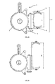
- the Figure 2A is a side view of the securing device according to the invention in which the adjustable jaw is in minimum extension.
- the Figure 2B is a profile view of the same securing device in which the adjustable jaw is in maximum extension.
- the figure 3A refers to a view from above of the securing device.
- the figure 3B represents a sectional view according to section AA of the figure 3A .
- the figure 4 is a front view of the securing device.
- the figure 5 refers to a side view of the securing device.
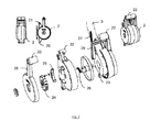
- the figure 6 is an exploded view, in perspective, of the various constituent parts of the securement device according to the invention.
- the figure 7 illustrates the details of the mini-winch (the adjustable jaw is not shown).
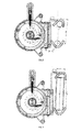
- the figure 8 is a profile view of the device of the invention in broken lines the internal mechanism.
- the device is attached to a roof rack comprising two bars of circular section while the figure 9 illustrates the attachment to a roof rack comprising a large bar of rectangular section.
- the figure 10 relates to a perspective view of the device of the invention presented to the figure 8 and stowed to a roof rack comprising two bars of circular section.
- the figure 11 relates to a perspective view of the device of the invention secured to the protective mesh of a pick-up cabin.
- the invention relates to a device for securing a load on a vehicle.
- the generic term charge refers to any object of any shape and weight.
- the vehicles may be motor vehicles, for example, vans, trucks, or passenger cars and station wagons. Vehicles may also be non-motorized vehicles, such as trailers.
- the securement device is intended to be fixed to a support located on the vehicle.
- the support is an amount of a van roof rack, an amount of a car rack or the protective mesh used on utility vehicles such as pick-ups or trailers.
- the support is preferably vertical and of dimension, and more precisely, of sufficient height to allow the fixation of the securing device.
- said device is adaptable to different support dimensions comprising two support points spaced vertically at least 50 mm. This excludes small section amounts such as for example, recent motor vehicles with two longitudinal bars less than 20 mm thick.
- the presence of two support points separated by a minimum space allows a stable attachment of the device to the amount and thus prevents its tilting.
- the two points of support are for example the two parallel bars constituting the longitudinal bar of the roof rack.
- the two points of support are the opposite sides of the single longitudinal bar.
- Such a securing device has the function of keeping the objects on the support during transport and to avoid both their loss and their degradation due to uncontrolled movements of these objects relative to the support.
- the securing device is removable, that is to say that it can be easily removed from the support between each use, as opposed to devices bolted or integrated support.
- the securing device 1 as presented to the Figure 2A and 2B comprises a mini-winch 2, also called strap winder, and an adjustable jaw 4 which is integral thereto.
- the adjustable jaw 4 comprises a first element 5 and a second element 6, the assembly of which constitutes a clamp for fixing the device of the invention to the support.
- the first element 5 is movably mounted and the second element 6 is fixed.
- the first element of the jaw 5 can slide vertically to adapt the width L of the jaw to the size of the support to which it is attached.
- a threaded element 8 such as a threaded rod provided with a head or bolt, coupled to this element 5 (see FIG. Figures 2A, 2B , 3B and 6 ).
- FIGs 2A and the Figure 2B are side views of the lashing device 1 where the adjustable jaw 4 is in minimum extension ( Figure 2A ) or in maximum extension ( Figure 2B ).
- the distance between the two bearing points is 50 mm, and preferably 90 mm, whereas it is 200 mm in maximum extension, the minimum opening of the jaws being limited by the minimum dimensions of the box of the strap reel.
- the maximum opening is limited by the dimensions of the second element of the jaw.
- the second member of the jaw 6 is screwed to the mini-winch housing 2 and the first member of the jaw 5 is inserted between the housing and the second member 6.
- the figure 6 shows the details of the mounting parts of the securing device 1.
- the first element 5 of the jaw fits into a space delimited by a high bearing 9 and a
- the bearings 9,10 thus delimit the stroke of the movable element 5 and are secured to the mini-winch housing 2 by their insertion into grooves 30 of the housing.
- the movable member 5 is in the form of an S-shaped section comprising a vertical central portion terminated by two wings of opposite orientation 11, 12, the lower flange 12 abutting against the high bearing 9 when the jaw is in position. maximum extension while in minimum extension, it stops against the bottom bearing 10.
- the high bearing 9 is provided with a groove 31 in which the vertical part of the movable element 5 can slide.
- the upper flange 11 is fixed by means of a fastener 19 to a deformable seal 18 of flexible material, for example of the rubber type.
- This seal allows an adaptation of the element 5 to the exact dimension of the support which is pressed against it. It is the same for the second element of the jaw 6 which has deformable seals 18 attached to the support shoes 17.
- the first element 5 of the jaw comprises a single contact surface for holding the support while the second element 6 of the jaw has two separate contact surfaces to ensure a stable support through the triangulated system.
- the upper wing 11 preferably comprises fins 16 adapted to guide the strap during the securing of the object to be transported.
- the movable member 5 is threadably coupled to a bolt 8.
- the element 5 is provided in the lower flange 12 with a threaded hole 7 in which the bolt 8 is screwed or unscrewed. via the wheel 15 causes the vertical movement of the element 5, thus allowing to adjust its height to the size of the support to which it must be fixed.
- the bearings 9, 10 have an unthreaded hole and a diameter greater than the diameter of the body of the bolt 8 so that by turning the knob 15, the movable member 5 of the jaw is raised (or lowered) since it is screw (or unscrew) through bolt 8.
- the body of the bolt 8 is therefore positioned in three aligned holes, those of bearings (9,10) unthreaded and the threaded of the lower flange of the movable member 5 of the jaw.
- the mini-winch 2 is provided with a strap (not visible on the figure 6 but visible on Figures 10-11 ) one end of which is attached to the mini winch.
- the other end preferably includes a hook that can either attach to a latch bar 20 after surrounding the object to be transported, or attach to any lashing point of the support.
- the strap forms a strip of flexible material that can cover an object by marrying its external morphology or be wrapped around the object.
- woven or knitted textiles non-woven fabrics or strips of flexible plastic material.
- the fibers of textiles can be indifferently natural or artificial. Straps made of nylon or polyester fabric gave good results.
- the mini-winch 2 also comprises a handle 22 and a bar 21 serving as a guide for the strap 3.
- the mini-winch is made of plastic material such as polyamide loaded with fibers.
- plastic material such as polyamide loaded with fibers.
- PET marketed by Dupont de Nemours under the trademark RYNITE ® also gave good results.
- the figure 7 illustrates the details of the mini-winch 2 in an exploded diagram. It distinguishes the strap 3 which wraps around the drum 23.
- a gear system 24 ratchet 25 prevents the relaxation of the strap which can be tensioned by maneuvering the handle 22 formed by the ends of the two outer flanges and the Inner flange of the mini-winch housing 2.
- a spring 26 maintains a torsional moment force on the gear wheel with respect to the drum 23 and another spring 27 holds the pawl 25 in contact with a tooth of the toothed wheel 24.
- the spring 27 slides in a chamber formed by a groove in the inside of the handle 28 supporting the handle 22 of the outer flange of the mini-winch housing 2 and another groove 29 located in an inverted U-shaped piece slidable on the handle 28.
- the barrel e 21 serving as a guide for the strap 3 is integral with the housing and can rotate freely.
- the pawl 25 and the toothed wheel 24 are made of stainless steel.
- the device is attached to an amount of the roof rack comprising two bars of circular section.
- One end of the strap 3 is wound on the mini-winch 2 while the other end is fixed by means of a hook to the amount of the gallery located on the other side of the object to be transported.
- the object is covered by the strap 3.
- the figure 11 illustrates the attachment of the device to the protective mesh of the cabin of a pick-up.
- One end of the strap 3 is wound on the mini-winch 2 while the other end is fixed by means of a hook to an amount of the lattice.
- the object is surrounded by the strap 3.
- the width or section of the roof bar does not exceed 35 mm in order to allow optimal grip of the jaw.
Landscapes
- Engineering & Computer Science (AREA)
- Transportation (AREA)
- Mechanical Engineering (AREA)
- Fittings On The Vehicle Exterior For Carrying Loads, And Devices For Holding Or Mounting Articles (AREA)
Applications Claiming Priority (1)
| Application Number | Priority Date | Filing Date | Title |
|---|---|---|---|
| BE2014/0090A BE1022245B1 (fr) | 2014-02-10 | 2014-02-10 | Enrouleur de sangle universel et amovible pour vehicule |
Publications (2)
| Publication Number | Publication Date |
|---|---|
| EP2915696A1 true EP2915696A1 (de) | 2015-09-09 |
| EP2915696B1 EP2915696B1 (de) | 2016-12-14 |
Family
ID=50588519
Family Applications (1)
| Application Number | Title | Priority Date | Filing Date |
|---|---|---|---|
| EP15154352.7A Active EP2915696B1 (de) | 2014-02-10 | 2015-02-09 | Entfernbarer Universalgurtaufroller für Fahrzeug |
Country Status (4)
| Country | Link |
|---|---|
| EP (1) | EP2915696B1 (de) |
| BE (1) | BE1022245B1 (de) |
| DK (1) | DK2915696T3 (de) |
| ES (1) | ES2619174T3 (de) |
Cited By (1)
| Publication number | Priority date | Publication date | Assignee | Title |
|---|---|---|---|---|
| US10857930B1 (en) | 2019-10-02 | 2020-12-08 | Avraham Y. Levi | Load hold-down device with retractable strap |
Families Citing this family (1)
| Publication number | Priority date | Publication date | Assignee | Title |
|---|---|---|---|---|
| CN107878583B (zh) * | 2017-11-24 | 2023-06-30 | 开封大学 | 一种新型载物车 |
Citations (5)
| Publication number | Priority date | Publication date | Assignee | Title |
|---|---|---|---|---|
| US4900203A (en) | 1988-09-22 | 1990-02-13 | Pope Ronald W | Load-tie-down system and winch assembly |
| US5993127A (en) * | 1998-06-25 | 1999-11-30 | Shinn; Shawn M. | Load holding strap wrapper |
| US6322279B1 (en) | 1997-11-04 | 2001-11-27 | Sports Carriers, Inc. | Adjustable attachment device |
| US20040173707A1 (en) * | 2002-12-13 | 2004-09-09 | Tom Loudamy | Tie-down rewind tool |
| DE202010006966U1 (de) * | 2010-05-19 | 2010-08-05 | Berl, Andreas | Ladungsbeförderungsmittel, insbesondere Anhänger |
Family Cites Families (2)
| Publication number | Priority date | Publication date | Assignee | Title |
|---|---|---|---|---|
| US6939095B1 (en) * | 2004-02-12 | 2005-09-06 | Richard C. Hugg | Selectively removable tie-down anchor |
| TWM358085U (en) * | 2009-01-22 | 2009-06-01 | San-Lang Ding | Auxiliary rope-tying clamp structure of hand puller |
-
2014
- 2014-02-10 BE BE2014/0090A patent/BE1022245B1/fr not_active IP Right Cessation
-
2015
- 2015-02-09 EP EP15154352.7A patent/EP2915696B1/de active Active
- 2015-02-09 ES ES15154352.7T patent/ES2619174T3/es active Active
- 2015-02-09 DK DK15154352.7T patent/DK2915696T3/en active
Patent Citations (5)
| Publication number | Priority date | Publication date | Assignee | Title |
|---|---|---|---|---|
| US4900203A (en) | 1988-09-22 | 1990-02-13 | Pope Ronald W | Load-tie-down system and winch assembly |
| US6322279B1 (en) | 1997-11-04 | 2001-11-27 | Sports Carriers, Inc. | Adjustable attachment device |
| US5993127A (en) * | 1998-06-25 | 1999-11-30 | Shinn; Shawn M. | Load holding strap wrapper |
| US20040173707A1 (en) * | 2002-12-13 | 2004-09-09 | Tom Loudamy | Tie-down rewind tool |
| DE202010006966U1 (de) * | 2010-05-19 | 2010-08-05 | Berl, Andreas | Ladungsbeförderungsmittel, insbesondere Anhänger |
Cited By (1)
| Publication number | Priority date | Publication date | Assignee | Title |
|---|---|---|---|---|
| US10857930B1 (en) | 2019-10-02 | 2020-12-08 | Avraham Y. Levi | Load hold-down device with retractable strap |
Also Published As
| Publication number | Publication date |
|---|---|
| BE1022245B1 (fr) | 2016-03-04 |
| EP2915696B1 (de) | 2016-12-14 |
| DK2915696T3 (en) | 2017-03-27 |
| ES2619174T3 (es) | 2017-06-23 |
Similar Documents
| Publication | Publication Date | Title |
|---|---|---|
| FR2963294A1 (fr) | Dispositif de maintien d'accessoire avec des moyens de reglage, et ensemble associe. | |
| EP2915696B1 (de) | Entfernbarer Universalgurtaufroller für Fahrzeug | |
| FR2897027A1 (fr) | Dispositif d'arrimage d'un transpalette sur le plateau d'un camion | |
| FR2990168A1 (fr) | Siege, notamment pour vehicule automobile | |
| EP2885163A1 (de) | Dachträger | |
| EP2085266B1 (de) | Innerer Dachgepäckträger | |
| WO2015078965A1 (fr) | Agencement d'une zone de chargement a l'interieur d'un vehicule automobile | |
| FR2467115A1 (fr) | Dispositif d'arrimage d'objets divers, notamment sacs et valises dans un coffre de vehicule | |
| FR2886243A1 (fr) | Dispositif de maintien de sacs dans un vehicule automobile et vehicule correspondant | |
| EP3835133B1 (de) | Vorrichtung zum platzieren eines objektes auf einem fahrzeugdach | |
| EP3030460B1 (de) | Abdeckanordnung für einen laderaum eines kraftfahrzeugs | |
| FR2989338A1 (fr) | Dispositif de retenue laterale d'un objet transporte sur des barres de support transversales montees sur un vehicule | |
| WO2013171430A1 (fr) | Dispositif de transport muni d'un crochet d'attelage | |
| FR2988347A1 (fr) | Systeme de maintien de bagages par sangle et bride. | |
| EP2803534B1 (de) | Dachträgerelement | |
| EP1544031A2 (de) | Spannvorrichtung für Gurte | |
| FR2959461A1 (fr) | Tablette arriere de vehicule automobile | |
| FR3127163A1 (fr) | Carrosserie de véhicule routier de transport de marchandises munie d’un système de retenue d’au moins une porte arrière | |
| FR3070638B1 (fr) | Dispositif d’arrimage d’un siege amovible a un plancher de vehicule automobile. | |
| FR2864010A1 (fr) | Dispositif adaptable a une remorque pour charger et transporter un vehicule a 2 roues | |
| FR3083201A1 (fr) | Dispositif de fixation d'une roue de secours d'un vehicule automobile. | |
| FR3082470A1 (fr) | Systeme d'arrimage d'un chariot elevateur a l'interieur d'une carrosserie de vehicule routier de transport de marchandises | |
| FR3079186A1 (fr) | Dispositif de guidage de la sangle a performances de securite ameliorees | |
| FR3086255A1 (fr) | Procede de fixation d’un bouclier arriere de vehicule sur une traverse arriere | |
| EP1686009A2 (de) | Traggerüst für ein Fahrrad oder zum Schleppen eines Motorrades |
Legal Events
| Date | Code | Title | Description |
|---|---|---|---|
| PUAI | Public reference made under article 153(3) epc to a published international application that has entered the european phase |
Free format text: ORIGINAL CODE: 0009012 |
|
| AK | Designated contracting states |
Kind code of ref document: A1 Designated state(s): AL AT BE BG CH CY CZ DE DK EE ES FI FR GB GR HR HU IE IS IT LI LT LU LV MC MK MT NL NO PL PT RO RS SE SI SK SM TR |
|
| AX | Request for extension of the european patent |
Extension state: BA ME |
|
| 17P | Request for examination filed |
Effective date: 20160302 |
|
| RBV | Designated contracting states (corrected) |
Designated state(s): AL AT BE BG CH CY CZ DE DK EE ES FI FR GB GR HR HU IE IS IT LI LT LU LV MC MK MT NL NO PL PT RO RS SE SI SK SM TR |
|
| GRAP | Despatch of communication of intention to grant a patent |
Free format text: ORIGINAL CODE: EPIDOSNIGR1 |
|
| INTG | Intention to grant announced |
Effective date: 20160712 |
|
| GRAS | Grant fee paid |
Free format text: ORIGINAL CODE: EPIDOSNIGR3 |
|
| GRAA | (expected) grant |
Free format text: ORIGINAL CODE: 0009210 |
|
| AK | Designated contracting states |
Kind code of ref document: B1 Designated state(s): AL AT BE BG CH CY CZ DE DK EE ES FI FR GB GR HR HU IE IS IT LI LT LU LV MC MK MT NL NO PL PT RO RS SE SI SK SM TR |
|
| REG | Reference to a national code |
Ref country code: GB Ref legal event code: FG4D Free format text: NOT ENGLISH |
|
| REG | Reference to a national code |
Ref country code: CH Ref legal event code: EP |
|
| REG | Reference to a national code |
Ref country code: IE Ref legal event code: FG4D Free format text: LANGUAGE OF EP DOCUMENT: FRENCH |
|
| REG | Reference to a national code |
Ref country code: AT Ref legal event code: REF Ref document number: 853250 Country of ref document: AT Kind code of ref document: T Effective date: 20170115 |
|
| REG | Reference to a national code |
Ref country code: DE Ref legal event code: R096 Ref document number: 602015000952 Country of ref document: DE |
|
| REG | Reference to a national code |
Ref country code: FR Ref legal event code: PLFP Year of fee payment: 3 |
|
| PG25 | Lapsed in a contracting state [announced via postgrant information from national office to epo] |
Ref country code: LV Free format text: LAPSE BECAUSE OF FAILURE TO SUBMIT A TRANSLATION OF THE DESCRIPTION OR TO PAY THE FEE WITHIN THE PRESCRIBED TIME-LIMIT Effective date: 20161214 |
|
| REG | Reference to a national code |
Ref country code: NL Ref legal event code: FP |
|
| REG | Reference to a national code |
Ref country code: DK Ref legal event code: T3 Effective date: 20170321 |
|
| REG | Reference to a national code |
Ref country code: SE Ref legal event code: TRGR |
|
| REG | Reference to a national code |
Ref country code: LT Ref legal event code: MG4D |
|
| PG25 | Lapsed in a contracting state [announced via postgrant information from national office to epo] |
Ref country code: GR Free format text: LAPSE BECAUSE OF FAILURE TO SUBMIT A TRANSLATION OF THE DESCRIPTION OR TO PAY THE FEE WITHIN THE PRESCRIBED TIME-LIMIT Effective date: 20170315 Ref country code: LT Free format text: LAPSE BECAUSE OF FAILURE TO SUBMIT A TRANSLATION OF THE DESCRIPTION OR TO PAY THE FEE WITHIN THE PRESCRIBED TIME-LIMIT Effective date: 20161214 Ref country code: NO Free format text: LAPSE BECAUSE OF FAILURE TO SUBMIT A TRANSLATION OF THE DESCRIPTION OR TO PAY THE FEE WITHIN THE PRESCRIBED TIME-LIMIT Effective date: 20170314 |
|
| REG | Reference to a national code |
Ref country code: AT Ref legal event code: MK05 Ref document number: 853250 Country of ref document: AT Kind code of ref document: T Effective date: 20161214 |
|
| PG25 | Lapsed in a contracting state [announced via postgrant information from national office to epo] |
Ref country code: FI Free format text: LAPSE BECAUSE OF FAILURE TO SUBMIT A TRANSLATION OF THE DESCRIPTION OR TO PAY THE FEE WITHIN THE PRESCRIBED TIME-LIMIT Effective date: 20161214 Ref country code: HR Free format text: LAPSE BECAUSE OF FAILURE TO SUBMIT A TRANSLATION OF THE DESCRIPTION OR TO PAY THE FEE WITHIN THE PRESCRIBED TIME-LIMIT Effective date: 20161214 Ref country code: RS Free format text: LAPSE BECAUSE OF FAILURE TO SUBMIT A TRANSLATION OF THE DESCRIPTION OR TO PAY THE FEE WITHIN THE PRESCRIBED TIME-LIMIT Effective date: 20161214 |
|
| REG | Reference to a national code |
Ref country code: ES Ref legal event code: FG2A Ref document number: 2619174 Country of ref document: ES Kind code of ref document: T3 Effective date: 20170623 |
|
| PG25 | Lapsed in a contracting state [announced via postgrant information from national office to epo] |
Ref country code: RO Free format text: LAPSE BECAUSE OF FAILURE TO SUBMIT A TRANSLATION OF THE DESCRIPTION OR TO PAY THE FEE WITHIN THE PRESCRIBED TIME-LIMIT Effective date: 20161214 Ref country code: EE Free format text: LAPSE BECAUSE OF FAILURE TO SUBMIT A TRANSLATION OF THE DESCRIPTION OR TO PAY THE FEE WITHIN THE PRESCRIBED TIME-LIMIT Effective date: 20161214 Ref country code: IS Free format text: LAPSE BECAUSE OF FAILURE TO SUBMIT A TRANSLATION OF THE DESCRIPTION OR TO PAY THE FEE WITHIN THE PRESCRIBED TIME-LIMIT Effective date: 20170414 Ref country code: SK Free format text: LAPSE BECAUSE OF FAILURE TO SUBMIT A TRANSLATION OF THE DESCRIPTION OR TO PAY THE FEE WITHIN THE PRESCRIBED TIME-LIMIT Effective date: 20161214 Ref country code: CZ Free format text: LAPSE BECAUSE OF FAILURE TO SUBMIT A TRANSLATION OF THE DESCRIPTION OR TO PAY THE FEE WITHIN THE PRESCRIBED TIME-LIMIT Effective date: 20161214 |
|
| PG25 | Lapsed in a contracting state [announced via postgrant information from national office to epo] |
Ref country code: SM Free format text: LAPSE BECAUSE OF FAILURE TO SUBMIT A TRANSLATION OF THE DESCRIPTION OR TO PAY THE FEE WITHIN THE PRESCRIBED TIME-LIMIT Effective date: 20161214 Ref country code: AT Free format text: LAPSE BECAUSE OF FAILURE TO SUBMIT A TRANSLATION OF THE DESCRIPTION OR TO PAY THE FEE WITHIN THE PRESCRIBED TIME-LIMIT Effective date: 20161214 Ref country code: BG Free format text: LAPSE BECAUSE OF FAILURE TO SUBMIT A TRANSLATION OF THE DESCRIPTION OR TO PAY THE FEE WITHIN THE PRESCRIBED TIME-LIMIT Effective date: 20170314 Ref country code: PT Free format text: LAPSE BECAUSE OF FAILURE TO SUBMIT A TRANSLATION OF THE DESCRIPTION OR TO PAY THE FEE WITHIN THE PRESCRIBED TIME-LIMIT Effective date: 20170414 Ref country code: PL Free format text: LAPSE BECAUSE OF FAILURE TO SUBMIT A TRANSLATION OF THE DESCRIPTION OR TO PAY THE FEE WITHIN THE PRESCRIBED TIME-LIMIT Effective date: 20161214 |
|
| REG | Reference to a national code |
Ref country code: DE Ref legal event code: R097 Ref document number: 602015000952 Country of ref document: DE |
|
| PG25 | Lapsed in a contracting state [announced via postgrant information from national office to epo] |
Ref country code: MC Free format text: LAPSE BECAUSE OF FAILURE TO SUBMIT A TRANSLATION OF THE DESCRIPTION OR TO PAY THE FEE WITHIN THE PRESCRIBED TIME-LIMIT Effective date: 20161214 |
|
| PLBE | No opposition filed within time limit |
Free format text: ORIGINAL CODE: 0009261 |
|
| STAA | Information on the status of an ep patent application or granted ep patent |
Free format text: STATUS: NO OPPOSITION FILED WITHIN TIME LIMIT |
|
| 26N | No opposition filed |
Effective date: 20170915 |
|
| REG | Reference to a national code |
Ref country code: IE Ref legal event code: MM4A |
|
| PG25 | Lapsed in a contracting state [announced via postgrant information from national office to epo] |
Ref country code: LU Free format text: LAPSE BECAUSE OF NON-PAYMENT OF DUE FEES Effective date: 20170209 |
|
| PG25 | Lapsed in a contracting state [announced via postgrant information from national office to epo] |
Ref country code: IE Free format text: LAPSE BECAUSE OF NON-PAYMENT OF DUE FEES Effective date: 20170209 Ref country code: SI Free format text: LAPSE BECAUSE OF FAILURE TO SUBMIT A TRANSLATION OF THE DESCRIPTION OR TO PAY THE FEE WITHIN THE PRESCRIBED TIME-LIMIT Effective date: 20161214 |
|
| REG | Reference to a national code |
Ref country code: FR Ref legal event code: PLFP Year of fee payment: 4 |
|
| PGFP | Annual fee paid to national office [announced via postgrant information from national office to epo] |
Ref country code: IT Payment date: 20180228 Year of fee payment: 4 |
|
| PGFP | Annual fee paid to national office [announced via postgrant information from national office to epo] |
Ref country code: ES Payment date: 20180413 Year of fee payment: 4 |
|
| PG25 | Lapsed in a contracting state [announced via postgrant information from national office to epo] |
Ref country code: MT Free format text: LAPSE BECAUSE OF FAILURE TO SUBMIT A TRANSLATION OF THE DESCRIPTION OR TO PAY THE FEE WITHIN THE PRESCRIBED TIME-LIMIT Effective date: 20161214 |
|
| PG25 | Lapsed in a contracting state [announced via postgrant information from national office to epo] |
Ref country code: HU Free format text: LAPSE BECAUSE OF FAILURE TO SUBMIT A TRANSLATION OF THE DESCRIPTION OR TO PAY THE FEE WITHIN THE PRESCRIBED TIME-LIMIT; INVALID AB INITIO Effective date: 20150209 |
|
| PG25 | Lapsed in a contracting state [announced via postgrant information from national office to epo] |
Ref country code: CY Free format text: LAPSE BECAUSE OF FAILURE TO SUBMIT A TRANSLATION OF THE DESCRIPTION OR TO PAY THE FEE WITHIN THE PRESCRIBED TIME-LIMIT Effective date: 20161214 |
|
| PG25 | Lapsed in a contracting state [announced via postgrant information from national office to epo] |
Ref country code: MK Free format text: LAPSE BECAUSE OF FAILURE TO SUBMIT A TRANSLATION OF THE DESCRIPTION OR TO PAY THE FEE WITHIN THE PRESCRIBED TIME-LIMIT Effective date: 20161214 |
|
| PG25 | Lapsed in a contracting state [announced via postgrant information from national office to epo] |
Ref country code: IT Free format text: LAPSE BECAUSE OF NON-PAYMENT OF DUE FEES Effective date: 20190209 |
|
| REG | Reference to a national code |
Ref country code: ES Ref legal event code: FD2A Effective date: 20200327 |
|
| PG25 | Lapsed in a contracting state [announced via postgrant information from national office to epo] |
Ref country code: TR Free format text: LAPSE BECAUSE OF FAILURE TO SUBMIT A TRANSLATION OF THE DESCRIPTION OR TO PAY THE FEE WITHIN THE PRESCRIBED TIME-LIMIT Effective date: 20161214 |
|
| PG25 | Lapsed in a contracting state [announced via postgrant information from national office to epo] |
Ref country code: ES Free format text: LAPSE BECAUSE OF NON-PAYMENT OF DUE FEES Effective date: 20190210 |
|
| PG25 | Lapsed in a contracting state [announced via postgrant information from national office to epo] |
Ref country code: AL Free format text: LAPSE BECAUSE OF FAILURE TO SUBMIT A TRANSLATION OF THE DESCRIPTION OR TO PAY THE FEE WITHIN THE PRESCRIBED TIME-LIMIT Effective date: 20161214 |
|
| PGFP | Annual fee paid to national office [announced via postgrant information from national office to epo] |
Ref country code: GB Payment date: 20220225 Year of fee payment: 8 Ref country code: DK Payment date: 20220225 Year of fee payment: 8 |
|
| PGFP | Annual fee paid to national office [announced via postgrant information from national office to epo] |
Ref country code: SE Payment date: 20220225 Year of fee payment: 8 |
|
| P01 | Opt-out of the competence of the unified patent court (upc) registered |
Effective date: 20230517 |
|
| REG | Reference to a national code |
Ref country code: DK Ref legal event code: EBP Effective date: 20230228 |
|
| REG | Reference to a national code |
Ref country code: SE Ref legal event code: EUG |
|
| GBPC | Gb: european patent ceased through non-payment of renewal fee |
Effective date: 20230209 |
|
| PG25 | Lapsed in a contracting state [announced via postgrant information from national office to epo] |
Ref country code: SE Free format text: LAPSE BECAUSE OF NON-PAYMENT OF DUE FEES Effective date: 20230210 |
|
| PG25 | Lapsed in a contracting state [announced via postgrant information from national office to epo] |
Ref country code: GB Free format text: LAPSE BECAUSE OF NON-PAYMENT OF DUE FEES Effective date: 20230209 |
|
| PG25 | Lapsed in a contracting state [announced via postgrant information from national office to epo] |
Ref country code: GB Free format text: LAPSE BECAUSE OF NON-PAYMENT OF DUE FEES Effective date: 20230209 Ref country code: DK Free format text: LAPSE BECAUSE OF NON-PAYMENT OF DUE FEES Effective date: 20230228 |
|
| PGFP | Annual fee paid to national office [announced via postgrant information from national office to epo] |
Ref country code: NL Payment date: 20240226 Year of fee payment: 10 |
|
| PGFP | Annual fee paid to national office [announced via postgrant information from national office to epo] |
Ref country code: DE Payment date: 20240228 Year of fee payment: 10 Ref country code: CH Payment date: 20240301 Year of fee payment: 10 |
|
| PGFP | Annual fee paid to national office [announced via postgrant information from national office to epo] |
Ref country code: FR Payment date: 20240226 Year of fee payment: 10 Ref country code: BE Payment date: 20240227 Year of fee payment: 10 |