EP2915218B1 - Steckverbinder mit isolierteil - Google Patents
Steckverbinder mit isolierteil Download PDFInfo
- Publication number
- EP2915218B1 EP2915218B1 EP13753584.5A EP13753584A EP2915218B1 EP 2915218 B1 EP2915218 B1 EP 2915218B1 EP 13753584 A EP13753584 A EP 13753584A EP 2915218 B1 EP2915218 B1 EP 2915218B1
- Authority
- EP
- European Patent Office
- Prior art keywords
- insulating part
- cover
- connector
- outer conductor
- opening
- Prior art date
- Legal status (The legal status is an assumption and is not a legal conclusion. Google has not performed a legal analysis and makes no representation as to the accuracy of the status listed.)
- Active
Links
- 239000004020 conductor Substances 0.000 claims description 87
- 230000037431 insertion Effects 0.000 claims description 4
- 238000003780 insertion Methods 0.000 claims description 4
- 230000000295 complement effect Effects 0.000 description 5
- 230000013011 mating Effects 0.000 description 4
- 230000007704 transition Effects 0.000 description 3
- 238000005452 bending Methods 0.000 description 2
- 238000002347 injection Methods 0.000 description 2
- 239000007924 injection Substances 0.000 description 2
- 230000015572 biosynthetic process Effects 0.000 description 1
- 238000002788 crimping Methods 0.000 description 1
- 230000001419 dependent effect Effects 0.000 description 1
- 238000006073 displacement reaction Methods 0.000 description 1
- 238000005553 drilling Methods 0.000 description 1
- 239000012777 electrically insulating material Substances 0.000 description 1
- 238000003754 machining Methods 0.000 description 1
- 238000004519 manufacturing process Methods 0.000 description 1
- 239000007787 solid Substances 0.000 description 1
Images
Classifications
-
- H—ELECTRICITY
- H01—ELECTRIC ELEMENTS
- H01R—ELECTRICALLY-CONDUCTIVE CONNECTIONS; STRUCTURAL ASSOCIATIONS OF A PLURALITY OF MUTUALLY-INSULATED ELECTRICAL CONNECTING ELEMENTS; COUPLING DEVICES; CURRENT COLLECTORS
- H01R13/00—Details of coupling devices of the kinds covered by groups H01R12/70 or H01R24/00 - H01R33/00
- H01R13/44—Means for preventing access to live contacts
- H01R13/447—Shutter or cover plate
-
- H—ELECTRICITY
- H01—ELECTRIC ELEMENTS
- H01R—ELECTRICALLY-CONDUCTIVE CONNECTIONS; STRUCTURAL ASSOCIATIONS OF A PLURALITY OF MUTUALLY-INSULATED ELECTRICAL CONNECTING ELEMENTS; COUPLING DEVICES; CURRENT COLLECTORS
- H01R13/00—Details of coupling devices of the kinds covered by groups H01R12/70 or H01R24/00 - H01R33/00
- H01R13/46—Bases; Cases
- H01R13/502—Bases; Cases composed of different pieces
-
- H—ELECTRICITY
- H01—ELECTRIC ELEMENTS
- H01R—ELECTRICALLY-CONDUCTIVE CONNECTIONS; STRUCTURAL ASSOCIATIONS OF A PLURALITY OF MUTUALLY-INSULATED ELECTRICAL CONNECTING ELEMENTS; COUPLING DEVICES; CURRENT COLLECTORS
- H01R13/00—Details of coupling devices of the kinds covered by groups H01R12/70 or H01R24/00 - H01R33/00
- H01R13/46—Bases; Cases
- H01R13/516—Means for holding or embracing insulating body, e.g. casing, hoods
-
- H—ELECTRICITY
- H01—ELECTRIC ELEMENTS
- H01R—ELECTRICALLY-CONDUCTIVE CONNECTIONS; STRUCTURAL ASSOCIATIONS OF A PLURALITY OF MUTUALLY-INSULATED ELECTRICAL CONNECTING ELEMENTS; COUPLING DEVICES; CURRENT COLLECTORS
- H01R13/00—Details of coupling devices of the kinds covered by groups H01R12/70 or H01R24/00 - H01R33/00
- H01R13/648—Protective earth or shield arrangements on coupling devices, e.g. anti-static shielding
Definitions
- the invention relates to a connector with an insulating part, which forms one or more holes for receiving a corresponding number of inner conductors. Through the insulating part, the inner conductors are kept electrically isolated within an outer conductor of the connector.
- the insulating part of the connector has a star-shaped cross section and forms a total of four holes in a square arrangement, which are provided for receiving in each case an inner conductor.
- the inner conductors are introduced via a respective radial slot in the associated bore and fixed therein positive and non-positive.
- the insulating part formed from an electrically insulating material ensures permanent positioning of the inner conductors at a distance to an outer conductor which completely surrounds the insulating part, air acting as a dielectric in the radial slots.
- the connector has an end which is provided for connection to a complementary connector. The other end is intended for connection to a cable.
- the corresponding cable-side ends of the inner conductors have two tabs, which form a crimp connection with the corresponding inner conductors of the cable be bent over. It may happen that not all individual wires of the inner conductor between the tabs are clamped and thus extend into the radial slots of the insulating part. This can lead to a short circuit when these individual wires contact the outer conductor of the connector.
- DE 10 2010 039314 A1 shows a connector according to the preamble of claim 1.
- the present invention seeks to provide a connector in which the described risk of short circuit is avoided by a contact between the inner conductor and outer conductor.
- An insulating part for a connector comprises a base body with (at least) one bore (not limited to machining by drilling, for example) for receiving (at least) an inner conductor of the connector and with (at least) one in the radial direction (with respect to a longitudinal axis of the bore ) opening into the bore through which the inner conductor can be introduced into the bore, and is inventively by a connected to the body cover, which releases the opening in a first position and conceals the opening in a second position, characterized.
- a corresponding connector according to the invention comprises (At least) an inventive insulating member, (at least) an inner conductor and (at least) an outer conductor.
- the cover is integrally connected to the main body.
- an insulating part may e.g. be made easily and inexpensively in the form of an injection molded from (electrically insulating) plastic.
- the insulating part is made such that the cover is in the first position after production.
- For the movement of the cover in the second position can then be provided at least local deformation of the cover.
- This local deformation can also be assisted in that the cover or the transition from the cover into the base body along a predetermined deformation line is weakened.
- a film hinge can be formed along this deformation line.
- the movement of the cover from the first to the second position preferably takes place about a pivot axis (this may in particular correspond to the deformation line), which runs in the direction of the longitudinal axis of the bore. It is understood by “in the direction” that the pivot axis with the longitudinal axis forms an angle of less than 90 ° and preferably less than 45 °. Particularly preferably, the pivot axis is parallel or coaxial with the longitudinal axis of the bore. This makes it possible inter alia to form the opening into the bore opening as a longitudinal opening, which also preferably extends parallel to the longitudinal axis of the bore. The longitudinal opening then makes it possible to introduce the inner conductor during assembly of the connector over its entire length simultaneously from the side and in particular via a parallel displacement in the bore.
- the cover during assembly of the Connector ie when the insulating is introduced into the outer conductor, automatically in the second position in which it covers the opening, is brought.
- the outer conductor may have a mounting opening, through which the insulating part can be introduced into this, wherein the arrangement of the mounting opening and the cover is such that the cover is moved by the introduction of the insulating part in the outer conductor in the second position.
- the introduction of the insulating part in the outer conductor preferably from the side (relative to a longitudinal axis of the connector in the region of the cover) take place.
- the outer conductor of the connector according to the invention for example, (at least) in that region in which it receives the cover of the insulating part, have a U-shaped cross-section.
- Such a cross-sectional shape of the outer conductor may i.a. be advantageously combined with an insulating part having at least two, preferably four parallel bores (for a corresponding number of inner conductors), wherein the opening into the holes openings extend to two sides of the body and the two sides of the body in each case one Cover is assigned.
- the two sides of the base body may preferably be formed mirror-symmetrically, so that a double-E-shaped cross-section (ie with a central longitudinal web and three these preferably perpendicular crossing transverse webs, one of which centrally and two end sides of the longitudinal web are arranged) of the main body of the Isoliertils can result.
- the two covers (which may preferably be arranged at the free ends of an outer crosspiece in a double-E-shaped cross-sectional shape) can then by contact with the outer legs of the cross-sectionally U-shaped outer conductor when plugging into the outer conductor in the respective second Position to be moved.
- the connector according to the invention may have a plug-side end and a cable-side end, the connection of the longitudinal direction and thus defining the longitudinal axis of the connector.
- the mounting opening of the outer conductor is arranged such that the insulating part can be introduced by a movement in the direction of alignment of the longitudinal axis at the plug-side end in the outer conductor.
- This allows an embodiment of the connector, in which the outer conductor is formed completely closed in the region of the plug-side end. This may be particularly advantageous if the outer conductor is provided in this area as a socket-shaped plug-in element of a plug connection formed with a complementary mating connector (or the outer conductor thereof).
- a lateral introduction of the cover (s) having portion of the insulating part in the there preferably U-shaped outer conductor may be provided when the cover (en) is provided in the region of the cable end, where these due to the connection of the / the inner conductor (s) with (one) regularly consisting of individual wires inner conductor (s) of a cable by eg Crimping is / are particularly advantageous.
- the forced movement of the cover (s) from the first to the second position can be achieved by arranging the pivot axis (s) of the cover (s) obliquely with respect to the direction of movement of the insulating member when inserted into the outer conductor. are and / or these on (a) correspondingly inclined edge (s) or surface (s) of the outer conductor slides / -n.
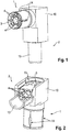
- the connector shown in the drawings is designed as an angle connector. This comprises a plug-side end as part of a plug-side portion 1, which is designed to form a plug connection with a complementary mating connector (not shown). Furthermore, the connector still comprises a cable-side end as part of a cable-side portion 2, which is provided for connecting a cable (not shown).
- the plug-side section 1 and the cable-side section 2 are at a 90 ° angle to each other. Accordingly, the plug-side end of the cable-side end connecting longitudinal axis of the connector also angled by 90 °.
- the connector comprises an integrally formed insulating part. This is formed as an injection molded part of an electrically insulating plastic.
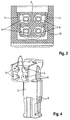
- a base body 3 of the insulating part has an angled course following the course of the connector and forms a plurality of (four in total) holes 4, which are more or less closed and interrupted in the region of the bend (the holes can thus also be spaced apart from one another Partial holes exist) - extend over the entire length of the insulating part.
- the holes 4 have in cross section a square arrangement within the base body 3. This corresponds to the usual arrangement of the four inner conductors used in HSD connectors.
- An inventive connector may be provided in particular as a HSD connector.
- the bores 4 are formed closed by more than 180 ° and in each case pass radially into a slot-shaped opening 5.
- a corresponding embodiment of the holes 4 can be found in a part of the plug-side section 1 of the insulating part. Completely closed, the holes 4 are only in the region of the plug-side end of the insulating part.
- the inner conductors 6 are held positively in the holes 4 by a kind of snap connection is formed between these and holding portions 7 of the holes in the plug-side portion 1 of the insulating part.
- the width of the respective slot-shaped opening 5 at the transition into the holding section 7 of the individual holes 4 is slightly smaller than the diameter of the associated portion of the respective inner conductor 6.
- the individual inner conductors 6 are formed as stamped bending components of an electrically conductive, metallic sheet.
- the inner conductors 6 are bent over in such a way that they have a (nearly) have closed (circular in cross-section) tubular shape.
- these can advantageously serve as a socket-shaped plug-in elements of the connector, can be plugged into the pin-shaped plug-in elements of inner conductors of a complementary mating connector.
- the inner conductor 6 are formed in the form of simple tabs. As a result, these can be bent well into a bend following the curved course.
- the inner conductors 6 form two successively arranged (almost) closed tubular sections 8, 9.
- first tubular portion 8 of each inner conductor 6 has a possible circular cross section and thereby ensures a largely backlash-free fit of the inner conductor 6 in the corresponding portion of the associated bore 4 of the insulating part.
- formation of a snap connection according to the holding portion 7 of the plug-side portion 1 of the insulating part can be formed here as well.
- the second tubular portion 9 forming tabs of the respective inner conductor 6, however, are more curved. As a result, they can be bent further in a simple manner in order to produce a crimp connection with the inner conductors of a cable (not shown) consisting of individual wires.
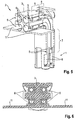
- FIGS. 5 and 6 show the covers 11 in a first position in which they do not obscure the slot-shaped openings 5.
- the insulating part is made with the covers 11 in this position.
- the covers When mounting the connector, the covers, however, in the in the Fig. 2 to 4 shown second position, which is accompanied by a local deformation of the covers 11 along deformation lines extending in the transitions of the covers 11 to the base body 3 parallel to the longitudinal axis of the connector in this area.
- This deformation can be elastic and / or plastic type.
- the slot-shaped openings 5 are covered by the covers 11, whereby a contact of not detected by the crimps strands with the outer conductor 10 is avoided.
- the inner conductor 6 are first introduced into the holes 4 of the insulating part and then inserted this unit in the outer conductor 10. This insertion takes place in the direction of the longitudinal axis of the connector in the plug-side section 1.
- the side opposite the plug-side end of the outer conductor 10 is provided with a corresponding mounting hole 12. Due to the bending of the connector, the introduction of the unit of insulating part and inner conductors 6 in the cable-side section 2 takes place from the side.
- the covers 11, which are still in the first position abut against the end faces of the outer legs of the outer conductor 10 provided with a U-shaped cross section in this section and are thereby forced into the second position.
- the covering of the slot-shaped openings 5 in the corresponding section of the insulating part thus takes place automatically by its introduction into the outer conductor 10. An additional assembly effort is not associated with it.
- this has a double-E-shaped cross-section, ie this is formed by a central longitudinal web and three transverse webs, one of the longitudinal web centered and the other two cross at the end.
- the covers 11 are connected at one end to one of the outer transverse webs. The pivoting of the covers takes place around almost 90 °. After pivoting, the covers 11 bear on the middle and the other of the outer transverse webs.
- the mounting opening 12 of the outer conductor is still closed by a suitable cover (not shown).
- This cover also includes the second half of a tubular fitting 13 of the outer conductor 10, which is intended to externally enclose an outer conductor of the cable, whereby the electrical connection is made with the outer conductor of the connector.
- the connector 13 improves the stability of the connection between the cable and connector.
- the formed of an electrically conductive material outer conductor 10 is formed as a socket-shaped plug-in element into which a corresponding plug-in element of the complementary mating connector can be inserted.
- Longitudinal slots 14 allow a good radial elasticity.
- a housing of the connector forming outer conductor as provided in the present embodiment, of course, a arranged in a preferably electrically insulating housing outer conductor can be used.
Applications Claiming Priority (2)
| Application Number | Priority Date | Filing Date | Title |
|---|---|---|---|
| DE202012010451U DE202012010451U1 (de) | 2012-10-30 | 2012-10-30 | Steckverbinder mit Isolierteil |
| PCT/EP2013/002568 WO2014067595A1 (de) | 2012-10-30 | 2013-08-22 | Steckverbinder mit isolierteil |
Publications (2)
| Publication Number | Publication Date |
|---|---|
| EP2915218A1 EP2915218A1 (de) | 2015-09-09 |
| EP2915218B1 true EP2915218B1 (de) | 2016-11-09 |
Family
ID=47625454
Family Applications (1)
| Application Number | Title | Priority Date | Filing Date |
|---|---|---|---|
| EP13753584.5A Active EP2915218B1 (de) | 2012-10-30 | 2013-08-22 | Steckverbinder mit isolierteil |
Country Status (9)
| Country | Link |
|---|---|
| US (1) | US9362656B2 (ko) |
| EP (1) | EP2915218B1 (ko) |
| JP (1) | JP6034976B2 (ko) |
| KR (1) | KR101900377B1 (ko) |
| CN (1) | CN104769784B (ko) |
| CA (1) | CA2887690A1 (ko) |
| DE (1) | DE202012010451U1 (ko) |
| TW (1) | TWM472976U (ko) |
| WO (1) | WO2014067595A1 (ko) |
Cited By (1)
| Publication number | Priority date | Publication date | Assignee | Title |
|---|---|---|---|---|
| KR20170088772A (ko) * | 2016-01-25 | 2017-08-02 | 래이디올 에스.에이.에스. | 앵글드 다중 접촉부 커넥터 및 이의 조립 방법 |
Families Citing this family (5)
| Publication number | Priority date | Publication date | Assignee | Title |
|---|---|---|---|---|
| DE202013006067U1 (de) * | 2013-07-05 | 2013-08-12 | Rosenberger Hochfrequenztechnik Gmbh & Co. Kg | Steckverbinder |
| NL2012812B1 (en) * | 2014-05-14 | 2016-02-29 | Amphenol East Asia Electronic Tech (Shenzhen) Co Ltd | High-speed data connector. |
| DE102015105088B4 (de) * | 2015-04-01 | 2018-10-11 | Mitsumi Electronics Europe GmbH | Hochfrequenz-Winkelstecker |
| DE102015004486B3 (de) * | 2015-04-07 | 2016-06-30 | Rosenberger Hochfrequenztechnik Gmbh & Co. Kg | Verfahren zum Herstellen eines Steckverbinders und Steckverbinder |
| DE102015118306B3 (de) | 2015-10-27 | 2016-10-20 | Harting Electric Gmbh & Co. Kg | Isolierkörper für einen Steckverbinder |
Family Cites Families (17)
| Publication number | Priority date | Publication date | Assignee | Title |
|---|---|---|---|---|
| JP3161569B2 (ja) * | 1994-01-12 | 2001-04-25 | 富士写真フイルム株式会社 | 塗布方法 |
| JP3761667B2 (ja) | 1997-03-06 | 2006-03-29 | 矢崎総業株式会社 | コネクタ及びコネクタの組付方法 |
| CN1774835B (zh) * | 2003-03-14 | 2013-06-12 | 莫莱克斯公司 | 具有底座形状的基本传输通道链路组 |
| CN2682688Y (zh) * | 2004-02-18 | 2005-03-02 | 重庆鸿雁通信器材厂 | 三通端接射频同轴连接器 |
| DE502005003877D1 (de) | 2004-12-13 | 2008-06-05 | Rosenberger Hochfrequenztech | Isolierteil für hf-steckverbinder, insbesondere fakra-steckverbinder |
| US7175455B2 (en) * | 2005-04-15 | 2007-02-13 | Adc Telecommunications, Inc. | High density coaxial switching jack |
| JP2007134057A (ja) * | 2005-11-08 | 2007-05-31 | Yazaki Corp | 防水コネクタ |
| US7572133B2 (en) * | 2005-11-14 | 2009-08-11 | Cooper Technologies Company | Separable loadbreak connector and system |
| DE102006016882B4 (de) | 2006-04-04 | 2008-01-31 | ITT Manufacturing Enterprises, Inc., Wilmington | Steckverbinder |
| FR2921522A1 (fr) | 2007-09-20 | 2009-03-27 | Souriau Soc Par Actions Simpli | Connecteur pour cables ethernet et kit pour connecteur |
| JP5119940B2 (ja) * | 2008-01-17 | 2013-01-16 | 住友電装株式会社 | コネクタ |
| JP2009272155A (ja) | 2008-05-08 | 2009-11-19 | Honda Tsushin Kogyo Co Ltd | 電気コネクタ |
| US7736191B1 (en) * | 2008-05-27 | 2010-06-15 | Jerzy Roman Sochor | Implantable connector with protected contacts |
| US7828604B1 (en) * | 2009-05-27 | 2010-11-09 | Cheng Uei Precision Industry Co., Ltd. | Connector assembly |
| US7901251B1 (en) * | 2009-11-13 | 2011-03-08 | Cheng Uei Precision Industry Co., Ltd. | Audio connector |
| DE102010039314B4 (de) | 2010-08-13 | 2019-10-10 | Te Connectivity Germany Gmbh | Elektrischer Steckverbinder |
| US8439691B1 (en) * | 2011-12-21 | 2013-05-14 | Cheng Uei Precision Industry Co., Ltd. | Electrical connector for realizing a high signal transmission rate |
-
2012
- 2012-10-30 DE DE202012010451U patent/DE202012010451U1/de not_active Expired - Lifetime
-
2013
- 2013-08-22 WO PCT/EP2013/002568 patent/WO2014067595A1/de active Application Filing
- 2013-08-22 EP EP13753584.5A patent/EP2915218B1/de active Active
- 2013-08-22 CN CN201380057214.6A patent/CN104769784B/zh active Active
- 2013-08-22 US US14/439,314 patent/US9362656B2/en active Active
- 2013-08-22 JP JP2015538309A patent/JP6034976B2/ja not_active Expired - Fee Related
- 2013-08-22 KR KR1020157012422A patent/KR101900377B1/ko active IP Right Grant
- 2013-08-22 CA CA 2887690 patent/CA2887690A1/en not_active Abandoned
- 2013-09-17 TW TW102217478U patent/TWM472976U/zh not_active IP Right Cessation
Cited By (2)
| Publication number | Priority date | Publication date | Assignee | Title |
|---|---|---|---|---|
| KR20170088772A (ko) * | 2016-01-25 | 2017-08-02 | 래이디올 에스.에이.에스. | 앵글드 다중 접촉부 커넥터 및 이의 조립 방법 |
| US10601165B2 (en) | 2016-01-25 | 2020-03-24 | Raydiall | Angled multi-contact connector and assembly method thereof |
Also Published As
| Publication number | Publication date |
|---|---|
| KR101900377B1 (ko) | 2018-09-20 |
| WO2014067595A1 (de) | 2014-05-08 |
| KR20150065893A (ko) | 2015-06-15 |
| CN104769784B (zh) | 2016-12-28 |
| JP2015536537A (ja) | 2015-12-21 |
| CA2887690A1 (en) | 2014-05-08 |
| CN104769784A (zh) | 2015-07-08 |
| TWM472976U (zh) | 2014-02-21 |
| US20150303606A1 (en) | 2015-10-22 |
| JP6034976B2 (ja) | 2016-11-30 |
| EP2915218A1 (de) | 2015-09-09 |
| US9362656B2 (en) | 2016-06-07 |
| DE202012010451U1 (de) | 2013-01-02 |
Similar Documents
| Publication | Publication Date | Title |
|---|---|---|
| EP3020101B1 (de) | Steckverbinder | |
| EP2915218B1 (de) | Steckverbinder mit isolierteil | |
| EP1236248B1 (de) | Verbindungskabel mit elektrischer steckverbindung sowie kabelmanager | |
| DE102013107807B3 (de) | Elektrische Steckverbindung | |
| EP2026417B1 (de) | Elektrischer Steckverbinder mit hermaphroditischen Kontaktelementen | |
| WO2014023386A1 (de) | Steckverbinder | |
| EP2797175B1 (de) | Stecker für ein mehrere Adern aufweisendes Daten- und/oder Telekommunikations-Kabel | |
| WO2014023383A1 (de) | Steckverbinder | |
| EP3625858A1 (de) | Steckverbinder mit schneidklemmkontakt | |
| EP2606538B1 (de) | Steckverbinder | |
| EP2061119A2 (de) | Kontaktelement und Verfahren zur Herstellung eines Kontaktelementes | |
| EP3196981A1 (de) | Querverbinder für reihenklemmen | |
| EP2243198B1 (de) | Koaxialwinkelsteckverbinder | |
| EP2453526A1 (de) | Verbindungsvorrichtung und Verfahren zur Herstellung einer elektrisch leitenden Verbindung | |
| EP3714513A1 (de) | Elektrischer verbinder und damit ausgestattete elektrische leitungsanordnung | |
| EP1587172B1 (de) | Steckbuchse zum elektrisch leitenden Verbinden mit einem Steckstift, insbesondere Flachsteckstift | |
| WO1998043321A1 (de) | Steckerbuchse mit in der form eines hyperboloids angeordneten kontaktbereichen | |
| EP1020954B1 (de) | Elektrische Anschlussklemme | |
| EP2551963B1 (de) | Elektrisches Anschlusselement | |
| DE102005054590A1 (de) | Elektrischer Steckverbinder | |
| EP1939987B1 (de) | Kontaktvorrichtung | |
| DE10227235A1 (de) | Leiteranschluss | |
| DE202010008456U1 (de) | Steckverbindung | |
| DE102012105901A1 (de) | Zugentlastungseinheit für einen elektrischen Steckverbinder und Gerätegehäuse | |
| EP2192658B1 (de) | Verbindungseinrichtung |
Legal Events
| Date | Code | Title | Description |
|---|---|---|---|
| PUAI | Public reference made under article 153(3) epc to a published international application that has entered the european phase |
Free format text: ORIGINAL CODE: 0009012 |
|
| 17P | Request for examination filed |
Effective date: 20150528 |
|
| AK | Designated contracting states |
Kind code of ref document: A1 Designated state(s): AL AT BE BG CH CY CZ DE DK EE ES FI FR GB GR HR HU IE IS IT LI LT LU LV MC MK MT NL NO PL PT RO RS SE SI SK SM TR |
|
| AX | Request for extension of the european patent |
Extension state: BA ME |
|
| RIN1 | Information on inventor provided before grant (corrected) |
Inventor name: SINGHAMMER, MARTIN Inventor name: BREDBECK, TILL Inventor name: ZEBHAUSER, MARTIN Inventor name: MUELLER, MICHAEL |
|
| DAX | Request for extension of the european patent (deleted) | ||
| REG | Reference to a national code |
Ref country code: DE Ref legal event code: R079 Ref document number: 502013005312 Country of ref document: DE Free format text: PREVIOUS MAIN CLASS: H01R0013502000 Ipc: H01R0013447000 |
|
| RIC1 | Information provided on ipc code assigned before grant |
Ipc: H01R 13/502 20060101ALI20160426BHEP Ipc: H01R 13/447 20060101AFI20160426BHEP Ipc: H01R 13/648 20060101ALI20160426BHEP Ipc: H01R 13/516 20060101ALI20160426BHEP |
|
| GRAP | Despatch of communication of intention to grant a patent |
Free format text: ORIGINAL CODE: EPIDOSNIGR1 |
|
| INTG | Intention to grant announced |
Effective date: 20160607 |
|
| GRAS | Grant fee paid |
Free format text: ORIGINAL CODE: EPIDOSNIGR3 |
|
| GRAA | (expected) grant |
Free format text: ORIGINAL CODE: 0009210 |
|
| AK | Designated contracting states |
Kind code of ref document: B1 Designated state(s): AL AT BE BG CH CY CZ DE DK EE ES FI FR GB GR HR HU IE IS IT LI LT LU LV MC MK MT NL NO PL PT RO RS SE SI SK SM TR |
|
| REG | Reference to a national code |
Ref country code: GB Ref legal event code: FG4D Free format text: NOT ENGLISH |
|
| REG | Reference to a national code |
Ref country code: AT Ref legal event code: REF Ref document number: 844683 Country of ref document: AT Kind code of ref document: T Effective date: 20161115 Ref country code: CH Ref legal event code: EP |
|
| REG | Reference to a national code |
Ref country code: DE Ref legal event code: R082 Ref document number: 502013005312 Country of ref document: DE Representative=s name: ZEITLER VOLPERT KANDLBINDER PATENTANWAELTE PAR, DE Ref country code: DE Ref legal event code: R082 Ref document number: 502013005312 Country of ref document: DE Representative=s name: ZEITLER VOLPERT KANDLBINDER PATENT- UND RECHTS, DE |
|
| REG | Reference to a national code |
Ref country code: IE Ref legal event code: FG4D Free format text: LANGUAGE OF EP DOCUMENT: GERMAN |
|
| REG | Reference to a national code |
Ref country code: DE Ref legal event code: R096 Ref document number: 502013005312 Country of ref document: DE |
|
| PG25 | Lapsed in a contracting state [announced via postgrant information from national office to epo] |
Ref country code: LV Free format text: LAPSE BECAUSE OF FAILURE TO SUBMIT A TRANSLATION OF THE DESCRIPTION OR TO PAY THE FEE WITHIN THE PRESCRIBED TIME-LIMIT Effective date: 20161109 |
|
| REG | Reference to a national code |
Ref country code: SE Ref legal event code: TRGR |
|
| REG | Reference to a national code |
Ref country code: LT Ref legal event code: MG4D |
|
| REG | Reference to a national code |
Ref country code: NL Ref legal event code: MP Effective date: 20161109 |
|
| PG25 | Lapsed in a contracting state [announced via postgrant information from national office to epo] |
Ref country code: NL Free format text: LAPSE BECAUSE OF FAILURE TO SUBMIT A TRANSLATION OF THE DESCRIPTION OR TO PAY THE FEE WITHIN THE PRESCRIBED TIME-LIMIT Effective date: 20161109 Ref country code: NO Free format text: LAPSE BECAUSE OF FAILURE TO SUBMIT A TRANSLATION OF THE DESCRIPTION OR TO PAY THE FEE WITHIN THE PRESCRIBED TIME-LIMIT Effective date: 20170209 Ref country code: GR Free format text: LAPSE BECAUSE OF FAILURE TO SUBMIT A TRANSLATION OF THE DESCRIPTION OR TO PAY THE FEE WITHIN THE PRESCRIBED TIME-LIMIT Effective date: 20170210 Ref country code: LT Free format text: LAPSE BECAUSE OF FAILURE TO SUBMIT A TRANSLATION OF THE DESCRIPTION OR TO PAY THE FEE WITHIN THE PRESCRIBED TIME-LIMIT Effective date: 20161109 |
|
| PG25 | Lapsed in a contracting state [announced via postgrant information from national office to epo] |
Ref country code: IS Free format text: LAPSE BECAUSE OF FAILURE TO SUBMIT A TRANSLATION OF THE DESCRIPTION OR TO PAY THE FEE WITHIN THE PRESCRIBED TIME-LIMIT Effective date: 20170309 Ref country code: PT Free format text: LAPSE BECAUSE OF FAILURE TO SUBMIT A TRANSLATION OF THE DESCRIPTION OR TO PAY THE FEE WITHIN THE PRESCRIBED TIME-LIMIT Effective date: 20170309 Ref country code: RS Free format text: LAPSE BECAUSE OF FAILURE TO SUBMIT A TRANSLATION OF THE DESCRIPTION OR TO PAY THE FEE WITHIN THE PRESCRIBED TIME-LIMIT Effective date: 20161109 Ref country code: ES Free format text: LAPSE BECAUSE OF FAILURE TO SUBMIT A TRANSLATION OF THE DESCRIPTION OR TO PAY THE FEE WITHIN THE PRESCRIBED TIME-LIMIT Effective date: 20161109 Ref country code: PL Free format text: LAPSE BECAUSE OF FAILURE TO SUBMIT A TRANSLATION OF THE DESCRIPTION OR TO PAY THE FEE WITHIN THE PRESCRIBED TIME-LIMIT Effective date: 20161109 Ref country code: FI Free format text: LAPSE BECAUSE OF FAILURE TO SUBMIT A TRANSLATION OF THE DESCRIPTION OR TO PAY THE FEE WITHIN THE PRESCRIBED TIME-LIMIT Effective date: 20161109 Ref country code: HR Free format text: LAPSE BECAUSE OF FAILURE TO SUBMIT A TRANSLATION OF THE DESCRIPTION OR TO PAY THE FEE WITHIN THE PRESCRIBED TIME-LIMIT Effective date: 20161109 |
|
| PG25 | Lapsed in a contracting state [announced via postgrant information from national office to epo] |
Ref country code: EE Free format text: LAPSE BECAUSE OF FAILURE TO SUBMIT A TRANSLATION OF THE DESCRIPTION OR TO PAY THE FEE WITHIN THE PRESCRIBED TIME-LIMIT Effective date: 20161109 Ref country code: CZ Free format text: LAPSE BECAUSE OF FAILURE TO SUBMIT A TRANSLATION OF THE DESCRIPTION OR TO PAY THE FEE WITHIN THE PRESCRIBED TIME-LIMIT Effective date: 20161109 Ref country code: RO Free format text: LAPSE BECAUSE OF FAILURE TO SUBMIT A TRANSLATION OF THE DESCRIPTION OR TO PAY THE FEE WITHIN THE PRESCRIBED TIME-LIMIT Effective date: 20161109 Ref country code: SK Free format text: LAPSE BECAUSE OF FAILURE TO SUBMIT A TRANSLATION OF THE DESCRIPTION OR TO PAY THE FEE WITHIN THE PRESCRIBED TIME-LIMIT Effective date: 20161109 Ref country code: DK Free format text: LAPSE BECAUSE OF FAILURE TO SUBMIT A TRANSLATION OF THE DESCRIPTION OR TO PAY THE FEE WITHIN THE PRESCRIBED TIME-LIMIT Effective date: 20161109 |
|
| REG | Reference to a national code |
Ref country code: DE Ref legal event code: R097 Ref document number: 502013005312 Country of ref document: DE |
|
| REG | Reference to a national code |
Ref country code: FR Ref legal event code: PLFP Year of fee payment: 5 |
|
| PG25 | Lapsed in a contracting state [announced via postgrant information from national office to epo] |
Ref country code: SM Free format text: LAPSE BECAUSE OF FAILURE TO SUBMIT A TRANSLATION OF THE DESCRIPTION OR TO PAY THE FEE WITHIN THE PRESCRIBED TIME-LIMIT Effective date: 20161109 Ref country code: BG Free format text: LAPSE BECAUSE OF FAILURE TO SUBMIT A TRANSLATION OF THE DESCRIPTION OR TO PAY THE FEE WITHIN THE PRESCRIBED TIME-LIMIT Effective date: 20170209 |
|
| PLBE | No opposition filed within time limit |
Free format text: ORIGINAL CODE: 0009261 |
|
| STAA | Information on the status of an ep patent application or granted ep patent |
Free format text: STATUS: NO OPPOSITION FILED WITHIN TIME LIMIT |
|
| 26N | No opposition filed |
Effective date: 20170810 |
|
| PG25 | Lapsed in a contracting state [announced via postgrant information from national office to epo] |
Ref country code: SI Free format text: LAPSE BECAUSE OF FAILURE TO SUBMIT A TRANSLATION OF THE DESCRIPTION OR TO PAY THE FEE WITHIN THE PRESCRIBED TIME-LIMIT Effective date: 20161109 |
|
| REG | Reference to a national code |
Ref country code: CH Ref legal event code: PL |
|
| PG25 | Lapsed in a contracting state [announced via postgrant information from national office to epo] |
Ref country code: MC Free format text: LAPSE BECAUSE OF FAILURE TO SUBMIT A TRANSLATION OF THE DESCRIPTION OR TO PAY THE FEE WITHIN THE PRESCRIBED TIME-LIMIT Effective date: 20161109 |
|
| PG25 | Lapsed in a contracting state [announced via postgrant information from national office to epo] |
Ref country code: CH Free format text: LAPSE BECAUSE OF NON-PAYMENT OF DUE FEES Effective date: 20170831 Ref country code: LI Free format text: LAPSE BECAUSE OF NON-PAYMENT OF DUE FEES Effective date: 20170831 |
|
| REG | Reference to a national code |
Ref country code: IE Ref legal event code: MM4A |
|
| REG | Reference to a national code |
Ref country code: BE Ref legal event code: MM Effective date: 20170831 |
|
| PG25 | Lapsed in a contracting state [announced via postgrant information from national office to epo] |
Ref country code: LU Free format text: LAPSE BECAUSE OF NON-PAYMENT OF DUE FEES Effective date: 20170822 |
|
| PG25 | Lapsed in a contracting state [announced via postgrant information from national office to epo] |
Ref country code: IE Free format text: LAPSE BECAUSE OF NON-PAYMENT OF DUE FEES Effective date: 20170822 |
|
| REG | Reference to a national code |
Ref country code: FR Ref legal event code: PLFP Year of fee payment: 6 |
|
| PG25 | Lapsed in a contracting state [announced via postgrant information from national office to epo] |
Ref country code: BE Free format text: LAPSE BECAUSE OF NON-PAYMENT OF DUE FEES Effective date: 20170831 |
|
| PG25 | Lapsed in a contracting state [announced via postgrant information from national office to epo] |
Ref country code: MT Free format text: LAPSE BECAUSE OF FAILURE TO SUBMIT A TRANSLATION OF THE DESCRIPTION OR TO PAY THE FEE WITHIN THE PRESCRIBED TIME-LIMIT Effective date: 20161109 |
|
| PG25 | Lapsed in a contracting state [announced via postgrant information from national office to epo] |
Ref country code: HU Free format text: LAPSE BECAUSE OF FAILURE TO SUBMIT A TRANSLATION OF THE DESCRIPTION OR TO PAY THE FEE WITHIN THE PRESCRIBED TIME-LIMIT; INVALID AB INITIO Effective date: 20130822 |
|
| REG | Reference to a national code |
Ref country code: AT Ref legal event code: MM01 Ref document number: 844683 Country of ref document: AT Kind code of ref document: T Effective date: 20180822 |
|
| PG25 | Lapsed in a contracting state [announced via postgrant information from national office to epo] |
Ref country code: CY Free format text: LAPSE BECAUSE OF FAILURE TO SUBMIT A TRANSLATION OF THE DESCRIPTION OR TO PAY THE FEE WITHIN THE PRESCRIBED TIME-LIMIT Effective date: 20161109 |
|
| PG25 | Lapsed in a contracting state [announced via postgrant information from national office to epo] |
Ref country code: MK Free format text: LAPSE BECAUSE OF FAILURE TO SUBMIT A TRANSLATION OF THE DESCRIPTION OR TO PAY THE FEE WITHIN THE PRESCRIBED TIME-LIMIT Effective date: 20161109 |
|
| PG25 | Lapsed in a contracting state [announced via postgrant information from national office to epo] |
Ref country code: AT Free format text: LAPSE BECAUSE OF NON-PAYMENT OF DUE FEES Effective date: 20180822 |
|
| PG25 | Lapsed in a contracting state [announced via postgrant information from national office to epo] |
Ref country code: TR Free format text: LAPSE BECAUSE OF FAILURE TO SUBMIT A TRANSLATION OF THE DESCRIPTION OR TO PAY THE FEE WITHIN THE PRESCRIBED TIME-LIMIT Effective date: 20161109 |
|
| PG25 | Lapsed in a contracting state [announced via postgrant information from national office to epo] |
Ref country code: AL Free format text: LAPSE BECAUSE OF FAILURE TO SUBMIT A TRANSLATION OF THE DESCRIPTION OR TO PAY THE FEE WITHIN THE PRESCRIBED TIME-LIMIT Effective date: 20161109 |
|
| P01 | Opt-out of the competence of the unified patent court (upc) registered |
Effective date: 20230525 |
|
| PGFP | Annual fee paid to national office [announced via postgrant information from national office to epo] |
Ref country code: IT Payment date: 20230822 Year of fee payment: 11 Ref country code: GB Payment date: 20230822 Year of fee payment: 11 |
|
| REG | Reference to a national code |
Ref country code: DE Ref legal event code: R082 Ref document number: 502013005312 Country of ref document: DE Representative=s name: KANDLBINDER, MARKUS, DIPL.-PHYS., DE |
|
| PGFP | Annual fee paid to national office [announced via postgrant information from national office to epo] |
Ref country code: SE Payment date: 20230823 Year of fee payment: 11 Ref country code: FR Payment date: 20230824 Year of fee payment: 11 Ref country code: DE Payment date: 20230828 Year of fee payment: 11 |