EP2914568B1 - Butadienextraktionsverfahren - Google Patents
Butadienextraktionsverfahren Download PDFInfo
- Publication number
- EP2914568B1 EP2914568B1 EP13850380.0A EP13850380A EP2914568B1 EP 2914568 B1 EP2914568 B1 EP 2914568B1 EP 13850380 A EP13850380 A EP 13850380A EP 2914568 B1 EP2914568 B1 EP 2914568B1
- Authority
- EP
- European Patent Office
- Prior art keywords
- degasser
- fraction
- butadiene
- rectifier
- acetylenes
- Prior art date
- Legal status (The legal status is an assumption and is not a legal conclusion. Google has not performed a legal analysis and makes no representation as to the accuracy of the status listed.)
- Active
Links
Images


Classifications
-
- B—PERFORMING OPERATIONS; TRANSPORTING
- B01—PHYSICAL OR CHEMICAL PROCESSES OR APPARATUS IN GENERAL
- B01D—SEPARATION
- B01D3/00—Distillation or related exchange processes in which liquids are contacted with gaseous media, e.g. stripping
- B01D3/34—Distillation or related exchange processes in which liquids are contacted with gaseous media, e.g. stripping with one or more auxiliary substances
- B01D3/40—Extractive distillation
-
- C—CHEMISTRY; METALLURGY
- C07—ORGANIC CHEMISTRY
- C07C—ACYCLIC OR CARBOCYCLIC COMPOUNDS
- C07C7/00—Purification; Separation; Use of additives
- C07C7/04—Purification; Separation; Use of additives by distillation
- C07C7/05—Purification; Separation; Use of additives by distillation with the aid of auxiliary compounds
- C07C7/08—Purification; Separation; Use of additives by distillation with the aid of auxiliary compounds by extractive distillation
-
- B—PERFORMING OPERATIONS; TRANSPORTING
- B01—PHYSICAL OR CHEMICAL PROCESSES OR APPARATUS IN GENERAL
- B01D—SEPARATION
- B01D19/00—Degasification of liquids
- B01D19/0068—General arrangements, e.g. flowsheets
-
- B—PERFORMING OPERATIONS; TRANSPORTING
- B01—PHYSICAL OR CHEMICAL PROCESSES OR APPARATUS IN GENERAL
- B01D—SEPARATION
- B01D3/00—Distillation or related exchange processes in which liquids are contacted with gaseous media, e.g. stripping
- B01D3/14—Fractional distillation or use of a fractionation or rectification column
- B01D3/143—Fractional distillation or use of a fractionation or rectification column by two or more of a fractionation, separation or rectification step
-
- C—CHEMISTRY; METALLURGY
- C07—ORGANIC CHEMISTRY
- C07C—ACYCLIC OR CARBOCYCLIC COMPOUNDS
- C07C11/00—Aliphatic unsaturated hydrocarbons
- C07C11/12—Alkadienes
- C07C11/16—Alkadienes with four carbon atoms
- C07C11/167—1, 3-Butadiene
Definitions
- Embodiments disclosed here relate to recovery of butadiene from a mixed hydrocarbon stream. More specifically, embodiments disclosed herein relate to an improved butadiene extraction process wherein the degasser operates at an intermediate pressure.
- Butadiene is an important base chemical and is used, for example, to prepare synthetic rubbers (butadiene homopolymers, styrene-butadiene-rubber or nitrile rubber) or for preparing thermoplastic terpolymers (acrylonitrile-butadiene-styrene copolymers). Butadiene is also converted to sulfolane, chloroprene and 1,4-hexamethylenediamine (via 1,4-dichlorobutene and adiponitrile). Dimerization of butadiene also allows vinylcyclohexene to be generated, which can be dehydrogenated to form styrene.
- Butadiene can be prepared from saturated hydrocarbons by refining process or by thermal cracking (steam cracking) processes, in which case naphtha is typically used as the raw material.
- naphtha is typically used as the raw material.
- a mixture of methane, ethane, ethene, acetylene, propane, propene, propyne, allene, butenes, butadiene, butynes, methylallene, C 4 and higher hydrocarbons are obtained.
- the separation is carried out by extractive distillation, i.e. a distillation with addition of an extractant which has a higher boiling point than the mixture to be separated and which increases the differences in the relative volatilities of the components to be separated.
- extractive distillation i.e. a distillation with addition of an extractant which has a higher boiling point than the mixture to be separated and which increases the differences in the relative volatilities of the components to be separated.
- suitable extractants allows a crude 1,3-butadiene fraction to be obtained from the C 4 cut mentioned by means of extractive distillation, and said fraction is subsequently further purified in purifying distillation columns.
- the butadiene recovery processes typically use 3- or 4-column extractive distillation systems to separate a mixed C 4 stream into product fractions, including a lights / butane / butenes stream (Raffinate-1 product), a crude butadiene product, which may be sent to a conventional distillation system for further purification, and C 3 acetylenes (propyne) and C 4 acetylenes streams, which may be sent to a selective hydrogenation unit, for example.
- crude 1,3-butadiene refers to a hydrocarbon mixture which has been obtained from a C 4 cut from which at least 90% by weight of the sum of butanes and butenes, preferably at least 98% by weight of the sum of butanes and butenes, more preferably at least 99% by weight of the sum of butanes and butenes, and simultaneously at least 90% by weight of the C 4 acetylenes, preferably at least 96% by weight of the C 4 acetylenes, more preferably at least 99% by weight of the C 4 acetylenes, has been removed.
- Crude 1,3-butadiene contains the 1,3-butadiene product of value frequently in a proportion of at least 80% by weight, preferably 90% by weight, more preferably more than 95% by weight, remainder impurities.
- pure 1,3-butadiene refers to a hydrocarbon mixture which contains the 1,3-butadiene product of value in a proportion of at least 98% by weight, preferably of at least 99.5% by weight, more preferably in the range between 99.7 and 99.9% by weight, remainder impurities.
- Typical processes to recover butadiene from mixed C 4 streams include extractive distillation processes, which may incorporate use of selective solvents.
- extractive distillation processes are found, for example, in U.S. Patent Nos. 7,692,053 , 7,393,992 , 7,482,500 , 7,226,527 , 4,310,388 , and 7,132,038 , among others.
- the degasser may be operated at an overhead pressure of 413 (kPa 4.21 kg/cm 2 ) gage, slightly above the extractive distillation system (including the main washer, rectifier and afterwasher) pressure. Consequently, the degasser operates at correspondingly higher temperatures: about 148°C at the top of the degasser and about 193°C at the bottom of the degasser.
- the degasser in the conventional design may be operated at an overhead pressure of only 69 kPa (0.7 kg/cm 2 ) gage, and at much lower temperatures: about 105°C at the top of the degasser and about 149°C at the bottom of the degasser.
- US 8 252 150 B1 describes 1,3 butadiene recovered from a C 4 fraction containing butadienes, butenes, butanes, and acetylenes that is generated from a steam cracker by extractive distillation operating with no reflux or greatly reduced reflux conditions.
- WO2005/037396 A1 describes a process of 1,3-butadiene recovery from C 4 -hydrocarbon mixtures by means of extractive distillation with a selective solvent.
- butadiene extraction processes may be operated at an intermediate pressure using a liquid ring type compressor.
- a liquid ring compressor among other process options presented herein, may advantageously reduce capital and operating costs, similar to the compressorless option, while mitigating the risks associated with the higher operating temperatures and pressures associated with the compressorless option.
- the embodiments of the processes disclosed herein encompass the best features of the conventional design (low pressure, with a compressor) with the advantages of the compressorless design (low capital and operating cost), as well as other advantages unique to the systems disclosed herein.
- embodiments disclosed herein relate to a process for recovering 1,3-butadiene from a C 4 fraction.
- the process may include: feeding a hydrocarbon fraction containing butanes, butenes, 1,2-butadiene, 1,3-butadiene, C 4 acetylenes, C 3 acetylenes, and C 5+ hydrocarbons to an extractive distillation system; contacting the hydrocarbon fraction with a solvent in the extractive distillation system to selectively dissolve a portion of the hydrocarbon fraction; recovering a vapor fraction comprising a first portion of the butanes and the butenes from the extractive distillation system; recovering an enriched solvent fraction comprising the 1,3-butadiene, the 1,2-butadiene, C 4 acetylenes, C 3 acetylenes, C 5+ hydrocarbons, and a second portion of the butanes and the butenes; feeding the enriched solvent fraction to a rectifier to at least partially degas the enriched solvent; recovering a second portion
- inventions disclosed herein relate to a system for recovering 1,3-butadiene from a C 4 fraction.
- the system may include: a flow conduit for feeding a hydrocarbon fraction containing butanes, butenes, 1,2-butadiene, 1,3-butadiene, C 4 acetylenes, C 3 acetylenes, and C 5+ hydrocarbons to an extractive distillation system; the extractive distillation system for contacting the hydrocarbon fraction with a solvent in the extractive distillation system to selectively dissolve a portion of the hydrocarbon fraction; a flow conduit for recovering a vapor fraction comprising a first portion of the butanes and the butenes from the extractive distillation system; a flow conduit for recovering an enriched solvent fraction comprising the 1,3-butadiene, the 1,2-butadiene, C 4 acetylenes, C 3 acetylenes, C 5+ hydrocarbons, and a second portion of the butanes and the butenes; a flow conduit for
- Embodiments disclosed here relate to recovering butadiene from mixed C 4 hydrocarbon streams. More specifically, embodiments disclosed herein relate to improving the operations and economics of butadiene extraction processes via use of intermediate pressures and a liquid ring type compressor.
- the C 4 fraction to be used as starting mixture in the present processes is a mixture of hydrocarbons having predominantly four carbon atoms per molecule.
- C 4 fractions are obtained, for example, in the preparation of ethylene and/or propylene by thermal or catalytic cracking of a petroleum fraction, such as liquefied petroleum gas, light naphtha or gas oil.
- C 4 fractions may also be obtained by the catalytic dehydrogenation (oxidative and/or non-oxidative dehydrogenation) of n-butane and/or n-butene.
- the resulting C 4 fractions generally include butanes, n-butene, isobutene, 1,3-butadiene and small amounts of C 3 and C 5 hydrocarbons, including methylacetylene, as well as butynes, in particular 1-butyne (ethylacetylene) and butenyne (vinylacetylene).
- the 1,3-butadiene content is generally from 5 to 80% by weight.
- a cracker or a CATADIENE unit may contain 15 to 17% butadiene, by weight.
- Other mixed C 4 feed streams may contain greater or lesser amounts of butadiene.
- vinylacetylene When present in the mixed feed stream, vinylacetylene may be selectively hydrogenated to the desired 1,3-butadiene product prior to feed of the mixed C 4 stream to the butadiene extraction unit.
- the mixed C 4 hydrocarbon stream may be provided, for example, by at least one of cracking, oxidatively dehydrogenating, and non-oxidatively dehydrogenating a C 4 hydrocarbon stream comprising butane in one or more dehydrogenation reactors to produce a product gas stream comprising butane, butene, and butadiene.
- the above-described hydrocarbon fraction containing butanes, butenes, 1,2-butadiene, 1,3-butadiene, C 4 acetylenes, C 3 acetylenes, and C 5+ hydrocarbons, is fed to a butadiene extraction unit for separation and recovery of the various hydrocarbons, including one or more lights / butanes / butenes fractions (commonly referred to as a Raffinate-1 product), a 1,3-butadiene fraction, a C 3 acetylenes (propyne) fraction, a C 4 acetylenes fraction, which may include a portion of the 1,2-butadiene, and a heavies fraction, which may include a portion of the 1,2-butadiene and the C 5+ hydrocarbons.
- a butadiene extraction unit for separation and recovery of the various hydrocarbons, including one or more lights / butanes / butenes fractions (commonly referred to as a
- dimers of butadiene may be formed upstream of the butadiene extraction unit or during processing of the hydrocarbon fraction within the butadiene extraction unit.
- the vinylcyclohexene components may be recovered with the heavies fraction, or may be recovered as a separate fraction containing vinylcyclohexene.
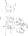
- a mixed hydrocarbon feed 2 including hydrocarbons such as butanes, butenes, 1,2-butadiene, 1,3-butadiene, methyl acetylene, vinyl acetylene, and C 5+ hydrocarbons, may be fed to a feed vaporization system (not shown) to vaporize the mixed hydrocarbon feed. The vaporized feed is then fed to main wash column 44.
- hydrocarbons such as butanes, butenes, 1,2-butadiene, 1,3-butadiene, methyl acetylene, vinyl acetylene, and C 5+ hydrocarbons
- main wash column 44 the vaporized feed is contacted with a solvent, and the butanes and butenes are separated from the more soluble 1,3-butadiene, 1,2-butadiene, methyl acetylene, vinyl acetylene, and C 5+ hydrocarbons.
- Solvents useful in the process as illustrated in Figure 1 may include butyrolactone, nitriles such as acetonitrile, propionitrile, methoxypropionitrile, ketones such as acetone, furfural, N-alkyl-substituted lower aliphatic amides such as dimethylformamide, diethylformamide, dimethylacetamide, diethylacetamide, N-formylmorpholine, N-alkyl-substituted cyclic amides (lactams) such as N-alkylpyrrolidones, especially N-methylpyrrolidone (NMP).
- alkyl-substituted lower aliphatic amides or N-alkyl-substituted cyclic amides, dimethylformamide, acetonitrile, furfural or NMP are used.
- NMP may be in aqueous solution, with from 0 to about 20 weight % water, or with from 7 to 10 weight % water, or with 8 to 8.5 weight % water in other embodiments.
- the butanes and butenes are recovered from main wash column 44 as an overheads fraction 8 (Raffinate 1).
- the enriched solvent, including the dissolved hydrocarbons, is recovered from main wash column 44 as a bottoms fraction 46.
- Bottoms fraction 46 is then fed to rectifier 48 to at least partially degas the enriched solvent.
- Any dissolved butanes and butenes, as well as other light components may be recovered from rectifier 48 as an overheads fraction 50, which may recycled for re-processing in main wash column 44.
- Methyl acetylene and butadienes, including both 1,2-butadiene and 1,3-butadiene, and C 5+ hydrocarbons may be recovered from rectifier 48 as a side draw 52, and a degassed solvent, which may contain various C 4 components including 1,2-butadiene, 1-butyne, and vinyl acetylene, may be recovered from rectifier 48 as a bottoms fraction 54.
- Bottoms fraction 54 may be fed to a degasser 56, for separation of the solvent, entrained C 4 components, and a C 4 acetylene fraction, which may also include 1,2-butadiene.
- the C 4 vapors may be recovered from degasser and cooling column 56 as an overheads fraction 58, which may be compressed via liquid ring compressor 60.
- Liquid ring compressor 60 serves two functions: compression of the degasser overhead fraction and cooling of the compressed gas before recycle to the rectifier 48. Following compression, a portion of the compressed gases may be recycled to rectifier 48.
- the compressed degasser overhead fraction may be recovered via flow line 88 and fed to a separator 90 to separate any condensed gases. The vapor fraction recovered from separator 90 may then be recycled via flow line 92 to rectifier 48.
- the condensate fraction may be recovered from separator 90 via flow line 94, at least a portion of which may be cooled via heat exchanger 96 and recycled to liquid ring compressor 60.
- a vinyl acetylene fraction may be withdrawn from degasser 56 as a side draw fraction 62, washed with water fed via line 64 in acetylene washer 66, and recovered as vinyl acetylene fraction 12.
- the degassed solvent may be recovered from degasser 56 as a bottoms fraction 68 for recycle and feed to main wash column 44 and afterwash column 70, where the hydrocarbons in the side draw fraction 52 may be separated from the solvent.
- Solvent may be recovered from afterwash column 70 as a bottoms fraction 72 and recycled to rectifier 48, and a crude butadiene product stream may be recovered from afterwash column 70 as an overheads fraction 74.
- the crude butadiene product leaves the extractive distillation section and is then fed to a methyl acetylene distillation column 76, where methyl acetylene is recovered as an overheads fraction 10.
- the bottoms fraction 78 contains the 1,3-butadiene, 1,2-butadiene, and heavier hydrocarbons, and is fed to butadiene fractionator 80.
- 1,3-Butadiene having a purity of greater than 99.6% is recovered from butadiene column 80 as an overheads fraction 6, and the 1,2-butadiene and heavies are recovered as a bottoms fraction 14.
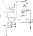
- the bottoms fraction recovered from the rectifier 48 via flow stream 54 may be heated via indirect heat exchange prior to feed to the degasser 56, such as via heat exchanger 98.
- the heating of the rectifier bottoms may vaporize a portion of the remaining dissolved gasses, such as 1,2-butadiene or C 4 acetylenes.
- the heated bottoms Prior to feeding of the heated rectifier bottoms to the degasser, the heated bottoms may be fed to a degasser feed drum 16 to phase separate the vaporized portion from the liquid portion of the effluent recovered from heater 98.
- a liquid phase may then be recovered from feed drum 16 and fed via flow line 18 to degasser 56 and processed as described above with respect to Figure 1 .
- the vapor phase recovered from feed drum 16 via flow line 40 may then be combined with the compressed vapor fraction of flow line 92 for recycle to rectifier 48.
- Degasser feed drum 16 may operate at a pressure slightly above the rectifier 48 bottoms pressure, allowing the vapor phase recovered from feed drum 16 to flow freely back to rectifier 48 without the need for vapor recompression. Some of the heat input added via exchanger 98 is thus returned to rectifier 48 in the form of the flashed vapors.
- the recycle of gas from drum 16 to rectifier 48 at a slightly elevated temperature may thus add heat to rectifier 48, and may result in additional pre-degassing in the bottom section of rectifier 48, contributing to an overall lower degassing requirement in degasser 56.
- Degasser feed drum 16 may be a separate vessel, or as illustrated, may be integral with the degasser 56, forming a single vessel structure. Integrating the feed drum and the degasser into a single vessel may reduce capital costs. By locating feed drum 16 above or on top of degasser 56, the liquid phase in the feed drum may easily flow into the top of the degasser without the need for additional pumps. Part of the heat input from exchanger 98 thus also flows to degasser 56 in the form of sensible heat contained in the un-flashed liquid fed to degasser 56 via flow line 18.
- exchanger 98 and phase separation in drum 16 may provide for two stages of flashing, in feed drum 16 and degasser 56, where feed drum 16 may be operated at a pressure greater than that of degasser 56.
- Use of the two stage separations may result in more efficient C4 degassing, improving separations of the C4 hydrocarbons from the solvent.
- dissolved gases degassed in feed drum 16 and recovered via flow line 40 are at a higher pressure level, and do not require recompression for recycle to rectifier 48.
- Degasser 56 may be operated at a pressure lower than rectifier 56, but only the gases recovered via flow line 58 require recompression. As a result, liquid ring compressor 60 may be sized to account for the reduced vapor flow and reduced compression requirements, resulting in lower capital and operating expenses.
- a ratio of the vapor flow rate of the compressed degasser overheads (stream 92) to the vapor flow rate of the vapor phase recovered from degasser feed drum 16 (stream 40) may be in the range from about 0.1:1 to about 1:1; in the range from about 0.2:1 to about 0.8:1 in other embodiments; and from about 0.25:1 to about 0.5:1 in yet other embodiments.
- the bottoms fraction recovered from the rectifier 48 via flow stream 54 may be heated via indirect heat exchange prior to feed to the degasser 56, such as via heat exchangers 4, 98, to vaporize a portion of the remaining dissolved gasses, such as 1,2-butadiene or C 4 acetylenes.
- Heat exchanger 4 may be used to recover heat from the bottoms fraction 68 recovered from degasser 56.
- Heat exchanger 98 may then be used further heat the rectifier bottoms before processing of the partially vaporized rectifier bottoms in degasser feed drum 16 and processed as described above with respect to Figure 2 .
- FIG. 4 a simplified flow diagram for a process for recovering 1,3-butadiene according to embodiments disclosed herein is illustrated, where like numerals represent like parts.
- the liquid portion recovered from degasser feed drum 16 via flow line 18 is heated via indirect heat exchange in heat exchanger 30 to provide addition heat to the degasser feed, which is then processed as described above.
- the rectifier bottoms may be heated via indirect heat exchange using exchangers 4, 98.
- exchanger 98 may use a heat exchange medium, such as water, steam, or a synthetic organic heat transfer fluid, such as DOWTHERM or others as may be known to those in the art. It may also be desirable to suppress vaporization in the heat exchangers and associated piping, favoring vaporization in feed drum 16 or degasser 56 to minimize or prevent fouling. Thus, in some embodiments, heat exchangers 4, 98 may be suppressed vaporization heaters.
- Degasser feed drum 16 may be operated at a pressure in the range from 343 kPa gage to 539 kPa gage (from 3.5 kg/cm 2 gage to 5.5 kg/cm 2 gage) in some embodiments; in the range from 392 kPa gage to 490 kPa gage (from 4 kg/cm 2 gage to 5 kg/cm 2 gage) in other embodiments; and from 417 kPa gage to 466 kPa gage (from 4.25 kg/cm 2 gage to 4.75 kg/cm 2 gage) in yet other embodiments, such as 441 kPa gage 4.5 kg/cm 2 gage).
- Degasser feed drum 16 may be operated at a temperature in the range from 110°C to 150°C in some embodiments; in the range from 120°C to 140°C in other embodiments; and in the range from 125°C to 135°C in yet other embodiments, such as 130°C.
- Degasser 56 may be operated at a pressure in the range from 147 kPa gage to 343 kPa gage (from 1.5 kg/cm 2 gage to 3.5 kg/cm 2 gage) in some embodiments; in the range from 196 kPa gage to 294 kPa gage (from 2 kg/cm 2 gage to 3 kg/cm 2 gage) in other embodiments; and from 221 kPa gage to 270 kPa gage (from 2.25 kg/cm 2 gage to 2.75 kg/cm 2 gage) in yet other embodiments, such as in the range from 226 kPa gage to 245 kPa gage (from 2.3 kg/cm 2 gage to 2.5 kg/cm 2 gage).
- Degasser 56 may be operated at an overhead temperature in the range from 100°C to 150°C in some embodiments; in the range from 110°C to 140°C in other embodiments; and in the range from 120°C to 130°C in yet other embodiments, such as 125°C.
- Degasser 56 may be operated at a bottoms temperature in the range from 150°C to 200°C in some embodiments; in the range from 160°C to 190°C in other embodiments; and in the range from 170°C to 180°C in yet other embodiments, such as 175°C.
- Rectifier 48 may be operated at a pressure in the range from 294 kPa gage to 490 kPa gage (from 3 kg/cm 2 gage to 5 kg/cm 2 gage) in some embodiments; in the range from 343 kPa gage to 441 kPa gage (from 3.5 kg/cm 2 gage to 4.5 kg/cm 2 gage) in other embodiments; and from 392 kPa gage to 441 kPa gage (from 4 kg/cm 2 gage to 4.5 kg/cm 2 gage) in yet other embodiments, such as in the range from 402 kPa gage to 412 kPa gage (from 4.1 kg/cm 2 gage to 4.2 kg/cm 2 gage).
- Rectifier 48 may be operated at an overhead temperature in the range from 40°C to 90°C in some embodiments; in the range from 50°C to 80°C in other embodiments; and in the range from 60°C to 70°C in yet other embodiments, such as in the range from 63 to 68°C. Rectifier 48 may be operated at a bottoms temperature in the range from 60°C to 120°C in some embodiments; in the range from 70°C to 110°C in other embodiments; and in the range from 75°C to 100°C in yet other embodiments, such as in the range from 80°C to 95°C.
- Heat may be supplied to the rectifier via indirect heat exchange in a reboiler using a heating medium having a temperature of less than 130°C.
- the heating medium used to heat the rectifier reboiler may have an operating temperature in the range from 80°C to 130°C in some embodiments; in the range from 90°C to 125°C in other embodiments; and in the range from 100°C to 120°C in yet other embodiments.
- the heat exchange medium used in the rectifier reboiler may be controlled such that the process-side temperature increase across the reboiler is in the range from 5°C to 15°C; and in the range from 8°C to 12°C in other embodiments, such as a delta of 10°C.
- the two-stage degassing provided for in the degasser feed drum 16 and the degasser 56, as well as heat introduced to rectifier 56 via vapor streams 40, 92 may allow the rectifier reboiler to operate at a low percent vaporization.
- the rectifier reboiler may operate having a percent vaporization across the reboiler in the range from 3 wt.% to 9 wt.%; in the range from 4 wt.% to 8 wt.% in other embodiments; and in the range from 5 wt.% to 7 wt.% in yet other embodiments, such as in the range from 6 wt.% to 6.5 wt%.
- the combination of low percent vaporization and low temperatures may significantly reduce fouling in the rectifier reboiler. Additionally, the low percent vaporization and reduced fouling may permit the rectifier reboiler to be a conventional type heat exchanger, including single-pass heat exchangers, as opposed to a suppressed vaporization type exchanger.
- a process for recovering butadiene according to embodiments disclosed herein, similar to that illustrated in Figure 3 , is compared to a conventional process for recovering butadiene (using a screw type or centrifugal compressor as well as a cooling column) and a compressorless process (also including a cooling column) for recovering butadiene, using the following conditions.
- the degasser is operated at an overhead pressure of 413 kPa gage (4.21 kg/cm 2 gage), slightly above the extractive distillation system (main washer, rectifier and afterwasher) pressure. Consequently, the degasser operates at correspondingly higher temperatures: 148°C at top and 193°C at bottom.
- the degasser operates at an overhead pressure of only 69 kPa gage (0.7 kg/cm 2 gage), and at much lower temperatures: 105°C at top and 149°C at bottom.
- the embodiment as illustrated in Figure 3 uses a once-through, co-current rectifier reboiler that uses partially cooled degasser bottoms (lean solvent) on the shell side. Partial vaporization (degassing) occurs in the reboiler tubes, and the vapor/liquid mixture is heated to 90°C. The partially degassed rich solvent at 90°C is then pumped by a degasser feed pump to subsequent exchangers where it is further heated in suppressed vaporization type exchangers. The degasser feed pump provides sufficient discharge pressure to ensure that no vaporization (degassing) occurs in any of the exchangers.
- the first exchanger is the tube side of the degasser feed/effluent exchanger, where the rich solvent is heated up to approximately 138°C on the tube side.
- the degasser feed/effluent exchanger is a two shell exchanger because of the large temperature cross that occurs in this exchanger.
- Degasser bottoms (lean solvent) at 175°C are used as the heating medium on the shell side of the exchanger.
- the lean solvent is cooled to 120°C in the degasser feed/effluent exchanger before being sent to the shell side of the rectifier reboiler and subsequently to the butadiene column reboiler, feed vaporizer, and solvent cooler.
- Heated rich solvent from the degasser feed/effluent exchanger is then sent to the degasser feed heater where the rich solvent is further heated against low pressure steam (150°C) to a temperature of approximately 138°C. Rich solvent at its final temperature is then flashed across a control valve into the degasser feed drum, which sits on top of the degasser. The feed drum rides off of the rectifier bottoms pressure, and the flashed gas flows freely back to the rectifier where it enters below the bottom bed. Un-flashed liquid from the degasser feed drum then flows by pressure difference/gravity into the top of the degasser where additional feed flashing occurs.
- the partially degassed solvent then flows down the multi-bed degasser, where essentially all of the remaining C 4 hydrocarbons are completely stripped from the solvent. Stripping heat is provided by the Degasser reboiler, utilizing medium pressure steam.
- the degasser also serves to concentrate the C 4 acetylenes (vinyl- and ethy-acetylene), 1,2-butadiene and VCH. These components are removed at their point of highest concentration via a liquid side draw.
- Table 1 A comparison of flow rates and energy requirements for these processes is presented in Table 1.
- Table 1. Unit Operation Example 1 Conventional Compressorless Degassing kg/h Duty mm kcal/h Temp. °C Degassing kg/h Duty mm kcal/h Temp. °C Degassing kg/h Duty mm kcal/h Temp.
- process heat (degasser bottoms) is advantageously exchanged for high pressure degassing (rectifier bottoms) and advantageously exchanged for low pressure degassing (degasser feed).
- Process heat is added to the rectifier bottoms (high pressure level) in two steps vs. the one-step heat addition in the conventional design.
- the first step is a "mild" heat input via the Rectifier reboiler, which is a once-thru reboiler that heats the rich solvent from 80°C to 90°C (only 10°C delta T). At this low outlet temperature, a suppressed-vaporization reboiler is not required, thus no rectifier bottoms pump is required.
- the percent vaporization in the rectifier reboiler is also quite low (6.2wt.%).
- the heating medium inlet temperature on the hot side of the rectifier reboiler is controlled at 120°C, which is significantly below the 150°C heating medium used in the conventional design. The combination of low temperatures (both hot side and cold side) and the low percent vaporization avoids the issue of fouling in the rectifier reboiler.
- Example 1 heats up the rectifier bottoms from 76°C to 120°C (44°C delta T) in the first degassing step.
- the process of Example 1 achieves almost half of the degassing as in the conventional design, with only a 10°C temperature rise vs. the 44°C temperature rise of the conventional design.
- the second step is a more "severe" heat input via the degasser feed/effluent exchanger, which requires a suppressed-vaporization reboiler (similar to the conventional design).
- the rich solvent is heated to about 140°C in a suppressed vaporization heater, the degasser feed/effluent exchanger, and flashed into the feed drum located at the top of (and part of) the degasser.
- the drum operates at a pressure slightly above the rectifier bottoms pressure, so the vapor flows freely back to the rectifier bottoms without the need for vapor recompression.
- the high level heat input is in the form of the flashed vapor returned to the rectifier.
- the un-flashed liquid then flows by pressure differential and gravity to the top of the degasser, where additional flashing occurs.
- the two-step high pressure degassing is also more efficient in terms of C 4 degassing.
- Two stages of flashing provide better separation of C 4 s from the solvent. In other words, more C 4 s and less solvent are vaporized compared to the conventional design.
- recycle gas is returned to the Rectifier at a slightly higher temperature than in the conventional design and more "pre-degassing" occurs in the bottom section of the rectifier. This contributes to an overall lower degassing requirement.
- Process heat is added to the degasser feed (low pressure degassing) by means of the sensible heat contained in the un-flashed liquid in the degasser feed drum.
- part of the heat input from the degasser feed/effluent exchanger ends up in the feed to the degasser.
- the capacity of the liquid ring compressor of Example 1 is only 60% of the capacity of the screw-type compressor required for the conventional design.
- the degasser operates at a pressure slightly less than 196 kPa (2 kg/cm 2 ) below the rectifier pressure. Consequently, the compression ratio required between the degasser and the rectifier is only 1.61 vs. 3.42 for the conventional design.
- the combination of lower flow and lower compression ratio allows the use of a liquid ring compressor instead of the more-expensive centrifugal or screw-type compressor employed in the conventional design.
- the smaller size (flow and compression ratio) of the liquid ring compressor makes it even less expensive.
- the cooling column used in the conventional design is eliminated in the process of Example 1, and its function is largely replaced by the liquid ring compressor.
- the liquid ring compressor accomplishes two operations: compressing the degasser overhead; and cooling the compressed gas.
- a second degasser feed heater can be added at the bottoms of the degasser feed drum to provide some additional low-level utility heat to the degasser feed.
- the heater could be located at grade and the liquid static head at the inlet to the exchanger would be used to suppress vaporization.
- the low pressure steam utilized would displace an equivalent amount of medium pressure steam, resulting in better economics. This option may also depend on project specific availability of low pressure steam and relative utility costs.
- the combined degasser feed drum/degasser design has no significant cost penalty.
- the degasser feed/effluent exchanger is a suppressed vaporization reboiler, there is already sufficient fluid pressure to overcome the static head to feed into the drum located at the higher elevation. In the conventional design this is simply chewed up across the control valve. Thus, there is no extra cost associated with pumping into the drum mounted on top of the degasser.
- the degasser is designed to be liquid-filled during chemical cleaning and passivation. The addition of a drum on the top of the degasser does not add significantly to the cost of the tower.
- the degasser operates at a higher pressure and temperature than the degasser in the conventional design. Although the bottoms temperature (175°C) is higher than the conventional design (150°C), it is significantly lower than the degasser bottoms temperature in the compressorless design (193°C). Thus, the process of Example 1 benefits from the pre-degassing in the bottom of the rectifier and the degassing and compression area.
- embodiments disclosed herein may have one or more of the following advantages. 1. Operation of the degasser at a higher pressure and temperature. 2. Replacement of the conventional recycle gas compressor (centrifugal or screw-type) with a smaller, less-expensive liquid ring compressor. 3. Replacement of the conventional solvent exchangers (3-shell design) with the following: a. rectifier reboiler (1 shell) b. degasser feed/effluent exchanger (2 shells). 4. Use of a feed flash drum mounted on top of the degasser.
- embodiments disclosed herein may have one or more of the following advantages. 1. Operation of the degasser at a lower pressure and temperature. 2. Replacement of the solvent exchangers (3-shell design) with a smaller rectifier reboiler (1-shell design). 3. Smaller degasser feed/effluent exchanger. 4. Addition of a small, low-cost liquid ring compressor, cooler and knock-out drum. 5. Addition of a feed flash drum mounted on top of the degasser. 6. elimination of the rectifier bottoms pumps (high capacity/high head). 7. Significantly less risk: degasser bottoms temperature is 175°C vs.
- butadiene extraction processes according to embodiments disclosed herein may be operated at a relative intermediate pressure using a liquid ring type compressor.
- a liquid ring compressor among other process options presented herein, may advantageously reduce capital and operating costs, similar to the compressorless option, while mitigating the risks associated with the higher operating temperatures and pressures of the compressorless option.
- the embodiments disclosed herein encompass the best features of the conventional design (low pressure, with a compressor) with the advantages of the compressorless design (low capital and operating cost), as well as other advantages unique to the systems disclosed herein.
Landscapes
- Chemical & Material Sciences (AREA)
- Organic Chemistry (AREA)
- Chemical Kinetics & Catalysis (AREA)
- Engineering & Computer Science (AREA)
- Analytical Chemistry (AREA)
- Oil, Petroleum & Natural Gas (AREA)
- Water Supply & Treatment (AREA)
- Organic Low-Molecular-Weight Compounds And Preparation Thereof (AREA)
- Structures Of Non-Positive Displacement Pumps (AREA)
- Vaporization, Distillation, Condensation, Sublimation, And Cold Traps (AREA)
- Production Of Liquid Hydrocarbon Mixture For Refining Petroleum (AREA)
Claims (25)
- Verfahren zur Gewinnung von 1,3 Butadien aus einer C4-Fraktion, umfassend:Zuführen einer Kohlenwasserstoff-Fraktion (2) enthaltend Butane, Butene, 1,2-Butadien, 1,3-Butadien, C4-Acetylene, C3-Acetylene, und C5+-Kohlenwasserstoffe in ein Extraktionsdestillationssystem (44);In-Kontakt-Bringen der Kohlenwasserstoff-Fraktion (2) mit einem Lösungsmittel in dem Extraktionsdestillationssystem (44), um selektiv einen Teil der Kohlenwasserstofffraktion (2) aufzulösen;Gewinnen einer Dampf-Fraktion (8) aufweisend einen ersten Teil der Butane und der Butene aus dem Extraktionsdestillationssystem (44);Gewinnen einer angereicherten Lösungsmittelfraktion (46), aufweisend das 1,3 Butadien, das 1,2 Butadien, C4-Acetylene, C3-Acetylene, C5+-Kohlenwasserstoffe, und einem zweiten Teil der Butane und der Butene;Zuführen der angereicherten Lösungsmittelfraktion (46) an einen Gleichrichter (48), um das angereicherte Lösungsmittel zumindest teilweise zu entgasen;Gewinnen eines zweiten Teils der Butane und Butene aus dem Gleichrichter (48) als Überkopffraktion (50);Gewinnen der C3 und C4-Acetylene, dem 1,3-Butadien, 1,2-Butadien, und der C5+ - Kohlenwasserstoffe aus dem Gleichrichter (48) als Seitenabzugsfraktion (52);Gewinnen eines teilweise entgasten Lösungsmittels (54) aufweisend 1,2 Butadien und C4-Acetylene aus dem Gleichrichter (48) als Bodenfraktion;Zuführen von zumindest einem Teil des teilweise entgasten Lösungsmittels (54) an einen Entgaser (56), um das Lösungsmittel weiter zu entgasen;Gewinnen einer Überkopffraktion (58) aufweisend zumindest C4-Acetylene und/oder 1,2-Butadien aus dem Entgaser (56);Gewinnen einer Seitenabzugsfraktion (62) aufweisend die C4-Acetylene aus dem Entgaser (56);Gewinnen einer Bodenfraktion (68) aufweisend entgastes Lösungsmittel aus dem Entgaser (56);Verdichten der Entgaser-Überkopffraktion (58) mithilfe eines Flüssigkeitsringverdichters (60); undRezyklieren von zumindest einem Teil der verdichteten Entgaser-Überkopffraktion (88) an den Gleichrichter (48).
- Verfahren nach Anspruch 1, ferner umfassend das Phasentrennen der verdichteten Entgaser-Überkopffraktion (88), um eine Kondensat-Fraktion (94) zu gewinnen und Rezyklieren von zumindest einem Teil der Kondensat-Fraktion (94) an den Flüssigkeitsringverdichter (60).
- Verfahren nach Anspruch 1, ferner umfassend:Erhitzen des teilweise entgasten Lösungsmittels (54) über indirekten Wärmeaustausch, um zumindest einen Teil der aufgelösten 1,2 Butadiene und/oder C4-Acetylene zu verdampfen;Zuführen des erhitzten, teilweise entgasten Lösungsmittels an eine Entgaserzufuhr-Trommel (16), um den verdampften Teil des 1,2-Butadiens und/oder C4-Acetylens von dem erhitzten, teilweise entgasten Lösungsmittel phasenzutrennen;Gewinnen einer Dampfphase (40) aus der Entgaserzufuhr-Trommel (16) aufweisend 1,2 Butadien und/oder C4-Acetylene;Gewinnen einer Flüssigphase (18) aus der Entgaserzufuhr-Trommel (16);Zuführen der Flüssigphase (18) aus der Entgaserzufuhr-Trommel (16) an den Entgaser (56) als den zumindest einen Teil des teilweise entgasten Lösungsmittels.
- Verfahren nach Anspruch 3, wobei die Entgaserzufuhr-Trommel (16) und der Entgaser (56) einstückig verbunden sind.
- Verfahren nach Anspruch 3, ferner umfassend das Vermischen der Gasphase (40), die aus der Entgaser-Zufuhrtrommel (16) gewonnen wurde, und des zumindest einen Teils des verdichteten Entgaser-Overheads sowie Rezyklieren des kombinierten Teils an den Gleichrichter (48).
- Verfahren nach Anspruch 5, wobei ein Verhältnis von dem zumindest einen Teil des Entgaser-Overheads zur Dampfphase in einem Bereich von etwa 0,1:1 bis 1:1 liegt.
- Verfahren nach Anspruch 3, wobei die Entgaserzufuhr-Trommel (16) bei einem Druck im Bereich von 343 bis 539 kPa (von 3,5 bis 5.5 kg/cm2) und einer Temperatur im Bereich von 120 °C bis 140 °C betrieben wird.
- Verfahren nach Anspruch 7, wobei der Druck des Entgasers (56) größer ist als ein Betriebsdruck des Gleichrichters (48).
- Verfahren nach Anspruch 3, wobei das Erhitzen des teilweise entgasten Lösungsmittels (54) mittels indirektem Wärmeaustausch zumindest einen der folgenden Schritt umfasst:In-Kontakt-bringen des teilweise entgasten Lösungsmittels (54) mit der Bodenfraktion des Entgasers (68) mittels indirektem Wärmeaustausch; undIn-Kontakt -bringen des teilweise entgasten Lösungsmittels (54) mit einem Wärmetauschmedium aufweisend ein synthetisches organisches Wärmeübertragungsfluid und/oder Wasser und/oder Dampf.
- Verfahren nach Anspruch 9, wobei (ein) Wärmetauscher (98) zum In-Kontakt-bringen des teilweise entgasten Lösungsmittels (54) einen Erhitzer mit unterdrückter Verdampfung umfasst.
- Verfahren nach Anspruch 1, wobei der Entgaser (56) bei einem Überkopfdruck im Bereich von 147 bis 343 kPa (von 1,5 bis 3.5 kg/cm2) und einer Überkopftemperatur im Bereich von 110 °C bis 140 °C betrieben wird.
- Verfahren nach Anspruch 11, wobei der Entgaser (56) bei einer Bodentemperatur im Bereich von 160 °C bis 190 °C betrieben wird.
- Verfahren nach Anspruch 1, wobei der Gleichrichter (48) bei einem Überkopfdruck im Bereich von 294 bis 490 kPa (von 3 bis 5 kg/cm2) und einer Überkopftemperatur im Bereich von 50 °C bis 70 °C betrieben wird.
- Verfahren nach Anspruch 13, wobei der Gleichrichter (48) bei einer Bodentemperatur im Bereich von 70 °C bis 100 °C betrieben wird.
- Verfahren nach Anspruch 14, wobei über indirekten Wärmeaustausch in einem Reboiler mithilfe eines Heizmediums mit einer Temperatur von weniger als 130 °C Wärme an den Gleichrichter (48) geliefert wird.
- Verfahren nach Anspruch 15, wobei der Reboiler einen Durchlauf-Wärmetauscher umfasst.
- Verfahren nach Anspruch 16, wobei eine Temperaturzunahme auf der Prozess-Seite über dem Reboiler im Bereich von 5 °C bis 15 °C liegt.
- Verfahren nach Anspruch 17, wobei eine Prozentverdampfung über dem Reboiler in Bereich von 3 Gewichtsprozent bis 9 Gewichtsprozent liegt.
- System zu Gewinnen von 1,3 Butadien aus einer C4-Fraktion, aufweisend:eine Strömungsleitung (2) zum Zuführen einer Kohlenwasserstoff-Fraktion enthaltend Butane, Butene, 1,2-Butadien, 1,3-Butadien, C4-Acetylene, C3-Acetylene, und C5+-Kohlenwasserstoffe in ein Extraktionsdestillationssystem (44);das Extraktionsdestillationssystem (44) zum In-Kontakt-Bringen der Kohlenwasserstoff-Fraktion mit einem Lösungsmittel in dem Extraktionsdestillationssystem (44), um selektiv einen Teil der Kohlenwasserstofffraktion aufzulösen;eine Strömungsleitung (8) zum Gewinnen einer Dampf-Fraktion aufweisend einen ersten Teil der Butane und der Butene aus dem Extraktionsdestillationssystem (44);eine Strömungsleitung (46) zum Gewinnen einer angereicherten Lösungsmittelfraktion aufweisend das 1,3 Butadien, das 1,2 Butadien, C4-Acetylene, C3-Acetylene, C5+-Kohlenwasserstoffe, und einem zweiten Teil der Butane und der Butene;eine Strömungsleitung (46) zum Zuführen der angereicherten Lösungsmittelfraktion an einen Gleichrichter (48); wobei der Gleichrichter (48) dazu dient, um das angereicherte Lösungsmittel zumindest teilweise zu entgasen;eine Strömungsleitung (50) zum Gewinnen eines zweiten Teils der Butane und Butene aus dem Gleichrichter (48) als Überkopffraktion (50);eine Strömungsleitung (52) zum Gewinnen der C3 und C4-Acetylene, dem 1,3-Butadien, 1,2-Butadien, und der C5+ -Kohlenwasserstoffe aus dem Gleichrichter (48) als Seitenabzugsfraktion;eine Strömungsleitung (54) zum Gewinnen eines teilweise entgasten Lösungsmittels (54) aufweisend 1,2 Butadien und C4-Acetylene aus dem Gleichrichter (48) als Bodenfraktion;eine Strömungsleitung (54) zum Zuführen von zumindest einem Teil des teilweise entgasten Lösungsmittels an einen Entgaser (56);wobei der Entgaser (56) zum Entgasen des Lösungsmittels dient;eine Strömungsleitung (58) zum Gewinnen einer Überkopffraktion aufweisend zumindest C4-Acetylene und/oder 1,2-Butadien aus dem Entgaser (56);eine Strömungsleitung (62) zum Gewinnen einer Seitenabzugsfraktion (62) aufweisend die C4-Acetylene aus dem Entgaser (56);eine Strömungsleitung (68) zum Gewinnen einer Bodenfraktion (68) aufweisend entgastes Lösungsmittel aus dem Entgaser (56);einen Flüssigkeitsringverdichter (60) zum Verdichten der Entgaser-Überkopffraktion; undeine Strömungsleitung (8) zum Rezyklieren von zumindest einem Teil der verdichteten Entgaser-Überkopffraktion an den Gleichrichter (48).
- System nach Anspruch 19, ferner aufweisend:einen Separator (90) zum Phasentrennen der verdichteten Entgaser-Überkopffraktion, um eine Kondensatfraktion zu gewinnen; undeine Strömungsleitung zum Rezylieren von zumindest einem Teil der Kondensatfraktion an den Flüssigkeitsringverdichter (60).
- System nach Anspruch 19, ferner aufweisend:einen Wärmetauscher zum Erhitzen des teilweise entgasten Lösungsmittels über indirekten Wärmeaustausch, um zumindest einen Teil des aufgelösten 1,2 Butadien und/oder C4-Azetylene zu verdampfen;eine Strömungsleitung zum Zuführen der erhitzen, teilweise entgasten Lösungsmittels an eine Entgaserzufuhrtrommel (16);wobei die Entgaserzufuhrtrommel (16) zum Phasentrennen des verdampften Teils des 1,2 Butadien und/oder C4 Acetylenen aus dem erhitzten, teilweise entgasten Lösungsmittel;eine Strömungsleitung (40) zum Gewinnen einer Dampfphase aus der Entgaserzufuhrtrommel (16) aufweisend 1,2 Butadien und/oder C4-Acetylene;eine Strömungsleitung zum Gewinnen einer Flüssigphase aus der Entgaserzufuhrtrommel (16) und Zuführen der Flüssigphase von der Entgaserzufuhrtrommel (16) an den Entgaser (56) als der zumindest eine Teil des teilweise entgasten Lösungsmittels.
- System nach Anspruch 21, ferner aufweisend eine Mischvorrichtung zum Mischen der Dampfphase, die aus der Entgaserzufuhrtrommel (16) gewonnen wurde, und des zumindest einen Teils des verdichteten Entgaser-Overheads und Rezyklieren des kombinierten Teils an den Gleichrichter (48).
- System nach Anspruch 21, wobei der Wärmetauscher zum Erhitzen des teilweise entgasten Lösungsmittels über indirekten Wärmeaustausch zumindest eine der folgenden Vorrichtungen aufweist:einen Wärmeaustauscher (4) zum In-Kontakt-bringen des teilweise entgasten Lösungsmittels mit der Entgaser-Bodenfraktion über indirekten Wärmeaustausch; undeinen Wärmeaustauscher (98) zum In-Kontakt-bringen des teilweise entgasten Lösungsmittels mit einem Wärmetauschmedium aufweisend Öl und/oder Wasser und/oder Dampf.
- System nach Anspruch 23, wobei der bzw. die Wärmeaustauscher (4, 98) zum In-Kontakt-bringen des teilweise entgasten Lösungsmittels einen Erhitzer mit unterdrückter Verdampfung aufweisen.
- System nach Anspruch 19, ferner aufweisend einen Reboiler, um Wärme an den Gleichrichter (48) über indirekten Wärmeaustausch zuzuführen, wobei der Reboiler einen Durchlauf-Wärmetauscher aufweist.
Priority Applications (1)
| Application Number | Priority Date | Filing Date | Title |
|---|---|---|---|
| PL13850380T PL2914568T3 (pl) | 2012-10-30 | 2013-10-15 | Sposób ekstrakcji butadienu |
Applications Claiming Priority (2)
| Application Number | Priority Date | Filing Date | Title |
|---|---|---|---|
| US201261720038P | 2012-10-30 | 2012-10-30 | |
| PCT/US2013/065056 WO2014070447A1 (en) | 2012-10-30 | 2013-10-15 | Butadiene extraction process |
Publications (3)
| Publication Number | Publication Date |
|---|---|
| EP2914568A1 EP2914568A1 (de) | 2015-09-09 |
| EP2914568A4 EP2914568A4 (de) | 2016-06-15 |
| EP2914568B1 true EP2914568B1 (de) | 2018-03-28 |
Family
ID=50547896
Family Applications (1)
| Application Number | Title | Priority Date | Filing Date |
|---|---|---|---|
| EP13850380.0A Active EP2914568B1 (de) | 2012-10-30 | 2013-10-15 | Butadienextraktionsverfahren |
Country Status (20)
| Country | Link |
|---|---|
| US (2) | US9296667B2 (de) |
| EP (1) | EP2914568B1 (de) |
| JP (1) | JP6050514B2 (de) |
| KR (1) | KR101788420B1 (de) |
| CN (1) | CN104903279B (de) |
| BR (1) | BR112015009737B1 (de) |
| CA (1) | CA2890134C (de) |
| ES (1) | ES2676398T3 (de) |
| HU (1) | HUE038577T2 (de) |
| IL (1) | IL238507A (de) |
| MX (1) | MX375366B (de) |
| MY (1) | MY175112A (de) |
| PH (1) | PH12015500960B1 (de) |
| PL (1) | PL2914568T3 (de) |
| PT (1) | PT2914568T (de) |
| RU (1) | RU2602807C1 (de) |
| SG (1) | SG11201503323YA (de) |
| TW (1) | TWI508947B (de) |
| WO (1) | WO2014070447A1 (de) |
| ZA (1) | ZA201502973B (de) |
Families Citing this family (11)
| Publication number | Priority date | Publication date | Assignee | Title |
|---|---|---|---|---|
| MX375617B (es) * | 2012-09-20 | 2025-03-06 | Lummus Technology Inc | Pre-absorbedor de extraccion de butadieno. |
| PH12015500877B1 (en) * | 2012-10-09 | 2022-07-15 | Lummus Technology Inc | Flexible butadiene extraction process |
| CN104307301B (zh) * | 2014-07-24 | 2016-03-30 | 襄阳航力机电技术发展有限公司 | 一种丁二烯尾气回收装置及其回收方法 |
| KR102287828B1 (ko) * | 2014-12-17 | 2021-08-10 | 에스케이이노베이션 주식회사 | 2,3-부탄디올의 탈수화 생성물로부터 1,3-부타디엔 및 메틸에틸케톤을 회수하는 방법 |
| KR102070309B1 (ko) * | 2015-11-13 | 2020-01-28 | 주식회사 엘지화학 | 공액디엔 제조장치 및 제조방법 |
| CN106083516B (zh) * | 2016-06-07 | 2018-09-18 | 安徽泰合森能源科技有限责任公司 | 采用萃取精馏脱除烷基化油生产原料中1,3-丁二烯的方法 |
| KR102383958B1 (ko) | 2017-12-28 | 2022-04-08 | 주식회사 엘지화학 | 미반응 단량체를 포함하는 혼합용액으로부터 미반응 단량체의 분리방법 |
| UA124434C2 (uk) * | 2019-06-04 | 2021-09-15 | Товариство З Обмеженою Відповідальністю "Виробнича Група "Техінсервіс" | СПОСІБ ОДЕРЖАННЯ 1,3-БУТАДІЄНУ ІЗ ЗМІШАНИХ ВУГЛЕВОДНІВ ФРАКЦІЇ С<sub>4</sub>+ |
| EP4077250A1 (de) * | 2019-12-19 | 2022-10-26 | SABIC Global Technologies B.V. | Butadien-wärmeintegrationsverfahren |
| CN115052850B (zh) * | 2020-02-06 | 2024-07-23 | 沙特基础工业全球技术公司 | 在c4的混合物的分离过程中提高萃取部分的可操作性以及调节溶剂的热回收循环的系统和方法 |
| CN119280863A (zh) * | 2024-12-11 | 2025-01-10 | 新疆昱华石油化工有限公司 | 一种1,2-丁二烯精馏制备装置及工艺 |
Citations (1)
| Publication number | Priority date | Publication date | Assignee | Title |
|---|---|---|---|---|
| WO2005037396A1 (en) * | 2003-10-20 | 2005-04-28 | Polski Koncern Natfowy Orlen Spolka Akcyjna | Butadiene recovery process |
Family Cites Families (25)
| Publication number | Priority date | Publication date | Assignee | Title |
|---|---|---|---|---|
| GB1050558A (de) * | 1964-09-04 | |||
| DE2516362C3 (de) | 1975-04-15 | 1987-10-22 | Basf Ag, 6700 Ludwigshafen | Verfahren zur Gewinnung von 1,3-Butadien aus einem C↓4↓-Kohlenwasserstoffgemisch |
| US4091046A (en) * | 1976-06-28 | 1978-05-23 | Phillips Petroleum Company | Production of isoprene from isobutane |
| US4038156A (en) * | 1976-09-21 | 1977-07-26 | Shell Oil Company | Butadiene recovery process |
| DE2724365C3 (de) * | 1977-05-28 | 1979-09-06 | Basf Ag, 6700 Ludwigshafen | Verfahren zum Trennen eines C4 -Kohlenwasserstoffgemisches durch extraktive Destillation |
| US4134795A (en) * | 1978-04-05 | 1979-01-16 | The Goodyear Tire & Rubber Company | Acetylenes removal from diolefin streams by extractive distillation |
| DE2911395C2 (de) | 1979-03-23 | 1985-03-14 | Basf Ag, 6700 Ludwigshafen | Verfahren zur Gewinnung eines konjugierten Diolefins aus einem C↓4↓- oder C↓5↓-Kohlenwasserstoffgemisch |
| SU792819A1 (ru) * | 1979-07-09 | 2000-12-20 | С.Г. Кузнецов | Способ разделения суглеводородных фракций |
| US4553983A (en) | 1984-07-31 | 1985-11-19 | Membrane Technology And Research, Inc. | Process for recovering organic vapors from air |
| FR2673178B1 (fr) * | 1991-02-26 | 1994-02-11 | Institut Francais Petrole | Procede de separation de butanes et de butenes par distillation extractive. |
| US5680775A (en) * | 1996-01-12 | 1997-10-28 | Manley; David B. | Demixing sidedraws for distillation columns |
| US6395952B1 (en) * | 1996-08-16 | 2002-05-28 | Stone & Webster Process Technology, Inc. | Chemical absorption process for recovering olefins from cracked gases |
| US6395953B1 (en) * | 1997-03-11 | 2002-05-28 | Nippon Zeon Co., Ltd. | Process for preparing purified conjugated diene |
| DE19818810A1 (de) * | 1998-04-27 | 1999-10-28 | Basf Ag | Verfahren zum Trennen eines C4-Kohlenwasserstoffgemisches |
| DE10056841A1 (de) | 2000-11-16 | 2002-05-23 | Basf Ag | Verfahren und Vorrichtung zur destillativen Gewinnung von 1,3-Reinbutadien aus 1,3-Rohbutadien |
| DE10105660A1 (de) * | 2001-02-08 | 2002-08-14 | Basf Ag | Verfahren zur Gewinnung von Roh-1,3-Butadien durch Extraktivdestillation aus einem C4-Schnitt |
| DE10233621A1 (de) | 2002-07-24 | 2004-02-19 | Basf Ag | Verfahren zur Aufarbeitung von Roh-1,3-Butadien |
| US8137548B2 (en) | 2003-10-17 | 2012-03-20 | Zirchrom Separations, Inc. | Chelator-modified inorganic oxide particles |
| DE10361824A1 (de) | 2003-12-30 | 2005-07-28 | Basf Ag | Verfahren zur Herstellung von Butadien |
| DE102004005930A1 (de) * | 2004-02-06 | 2005-08-25 | Basf Ag | Verfahren zur Gewinnung von Roh-1,3-Butadien |
| CN1305818C (zh) * | 2004-12-14 | 2007-03-21 | 青岛科大伊科思软件技术有限公司 | 双隔板塔提取粗1,3-丁二烯的装置及其方法 |
| US7348466B2 (en) * | 2005-04-13 | 2008-03-25 | Equistar Chemicals, Lp | Solvent extraction |
| KR101111015B1 (ko) | 2008-07-17 | 2012-04-04 | 에스케이이노베이션 주식회사 | 아세틸렌 전환공정을 이용한 c4 유분으로부터1,3-부타디엔을 분리하는 방법 |
| US8293960B2 (en) | 2009-08-17 | 2012-10-23 | Lummus Technology Inc. | Process for the production of butadiene |
| US8252150B1 (en) * | 2011-04-19 | 2012-08-28 | International Innotech Inc. | Extractive distillation process for recovering butadiene from C4 hydrocarbon mixtures |
-
2013
- 2013-10-15 EP EP13850380.0A patent/EP2914568B1/de active Active
- 2013-10-15 PT PT138503800T patent/PT2914568T/pt unknown
- 2013-10-15 JP JP2015539656A patent/JP6050514B2/ja not_active Expired - Fee Related
- 2013-10-15 MY MYPI2015001094A patent/MY175112A/en unknown
- 2013-10-15 KR KR1020157013485A patent/KR101788420B1/ko active Active
- 2013-10-15 RU RU2015120521/04A patent/RU2602807C1/ru active
- 2013-10-15 CA CA2890134A patent/CA2890134C/en not_active Expired - Fee Related
- 2013-10-15 ES ES13850380.0T patent/ES2676398T3/es active Active
- 2013-10-15 BR BR112015009737-5A patent/BR112015009737B1/pt not_active IP Right Cessation
- 2013-10-15 MX MX2015005503A patent/MX375366B/es active IP Right Grant
- 2013-10-15 PL PL13850380T patent/PL2914568T3/pl unknown
- 2013-10-15 HU HUE13850380A patent/HUE038577T2/hu unknown
- 2013-10-15 CN CN201380061757.5A patent/CN104903279B/zh active Active
- 2013-10-15 WO PCT/US2013/065056 patent/WO2014070447A1/en not_active Ceased
- 2013-10-15 SG SG11201503323YA patent/SG11201503323YA/en unknown
- 2013-10-21 US US14/058,637 patent/US9296667B2/en active Active
- 2013-10-22 TW TW102138064A patent/TWI508947B/zh active
-
2015
- 2015-04-28 IL IL238507A patent/IL238507A/en active IP Right Grant
- 2015-04-30 PH PH12015500960A patent/PH12015500960B1/en unknown
- 2015-04-30 ZA ZA2015/02973A patent/ZA201502973B/en unknown
-
2016
- 2016-03-03 US US15/059,771 patent/US9744475B2/en active Active
Patent Citations (1)
| Publication number | Priority date | Publication date | Assignee | Title |
|---|---|---|---|---|
| WO2005037396A1 (en) * | 2003-10-20 | 2005-04-28 | Polski Koncern Natfowy Orlen Spolka Akcyjna | Butadiene recovery process |
Also Published As
| Publication number | Publication date |
|---|---|
| US9296667B2 (en) | 2016-03-29 |
| CA2890134A1 (en) | 2014-05-08 |
| ZA201502973B (en) | 2016-02-24 |
| US9744475B2 (en) | 2017-08-29 |
| TWI508947B (zh) | 2015-11-21 |
| CA2890134C (en) | 2017-05-16 |
| BR112015009737A2 (pt) | 2017-07-04 |
| EP2914568A1 (de) | 2015-09-09 |
| JP2015533379A (ja) | 2015-11-24 |
| RU2602807C1 (ru) | 2016-11-20 |
| PH12015500960B1 (en) | 2020-01-31 |
| PL2914568T3 (pl) | 2018-10-31 |
| TW201429946A (zh) | 2014-08-01 |
| HUE038577T2 (hu) | 2018-10-29 |
| KR101788420B1 (ko) | 2017-11-15 |
| ES2676398T3 (es) | 2018-07-19 |
| WO2014070447A1 (en) | 2014-05-08 |
| MX2015005503A (es) | 2015-10-22 |
| JP6050514B2 (ja) | 2016-12-21 |
| KR20150084871A (ko) | 2015-07-22 |
| CN104903279B (zh) | 2017-05-10 |
| MY175112A (en) | 2020-06-08 |
| SG11201503323YA (en) | 2015-05-28 |
| IL238507A (en) | 2016-08-31 |
| BR112015009737B1 (pt) | 2020-10-13 |
| US20140121437A1 (en) | 2014-05-01 |
| EP2914568A4 (de) | 2016-06-15 |
| IL238507A0 (en) | 2015-06-30 |
| MX375366B (es) | 2025-03-04 |
| PH12015500960A1 (en) | 2015-08-17 |
| US20160184732A1 (en) | 2016-06-30 |
| CN104903279A (zh) | 2015-09-09 |
| PT2914568T (pt) | 2018-07-04 |
Similar Documents
| Publication | Publication Date | Title |
|---|---|---|
| EP2914568B1 (de) | Butadienextraktionsverfahren | |
| US10144682B2 (en) | Flexible butadiene extraction process | |
| US10118876B2 (en) | Butadiene extraction process | |
| CN114555546A (zh) | 用于通过萃取精馏、蒸馏、和/或选择性加氢制备1,3-丁二烯的集成系统和方法 |
Legal Events
| Date | Code | Title | Description |
|---|---|---|---|
| PUAI | Public reference made under article 153(3) epc to a published international application that has entered the european phase |
Free format text: ORIGINAL CODE: 0009012 |
|
| 17P | Request for examination filed |
Effective date: 20150521 |
|
| AK | Designated contracting states |
Kind code of ref document: A1 Designated state(s): AL AT BE BG CH CY CZ DE DK EE ES FI FR GB GR HR HU IE IS IT LI LT LU LV MC MK MT NL NO PL PT RO RS SE SI SK SM TR |
|
| AX | Request for extension of the european patent |
Extension state: BA ME |
|
| DAX | Request for extension of the european patent (deleted) | ||
| RA4 | Supplementary search report drawn up and despatched (corrected) |
Effective date: 20160513 |
|
| RIC1 | Information provided on ipc code assigned before grant |
Ipc: B01J 19/24 20060101ALI20160509BHEP Ipc: C07C 7/08 20060101AFI20160509BHEP Ipc: C07C 11/167 20060101ALI20160509BHEP |
|
| GRAP | Despatch of communication of intention to grant a patent |
Free format text: ORIGINAL CODE: EPIDOSNIGR1 |
|
| STAA | Information on the status of an ep patent application or granted ep patent |
Free format text: STATUS: GRANT OF PATENT IS INTENDED |
|
| INTG | Intention to grant announced |
Effective date: 20171002 |
|
| GRAJ | Information related to disapproval of communication of intention to grant by the applicant or resumption of examination proceedings by the epo deleted |
Free format text: ORIGINAL CODE: EPIDOSDIGR1 |
|
| STAA | Information on the status of an ep patent application or granted ep patent |
Free format text: STATUS: REQUEST FOR EXAMINATION WAS MADE |
|
| GRAR | Information related to intention to grant a patent recorded |
Free format text: ORIGINAL CODE: EPIDOSNIGR71 |
|
| GRAS | Grant fee paid |
Free format text: ORIGINAL CODE: EPIDOSNIGR3 |
|
| STAA | Information on the status of an ep patent application or granted ep patent |
Free format text: STATUS: GRANT OF PATENT IS INTENDED |
|
| GRAA | (expected) grant |
Free format text: ORIGINAL CODE: 0009210 |
|
| STAA | Information on the status of an ep patent application or granted ep patent |
Free format text: STATUS: THE PATENT HAS BEEN GRANTED |
|
| INTC | Intention to grant announced (deleted) | ||
| AK | Designated contracting states |
Kind code of ref document: B1 Designated state(s): AL AT BE BG CH CY CZ DE DK EE ES FI FR GB GR HR HU IE IS IT LI LT LU LV MC MK MT NL NO PL PT RO RS SE SI SK SM TR |
|
| INTG | Intention to grant announced |
Effective date: 20180219 |
|
| REG | Reference to a national code |
Ref country code: GB Ref legal event code: FG4D |
|
| REG | Reference to a national code |
Ref country code: CH Ref legal event code: EP |
|
| REG | Reference to a national code |
Ref country code: AT Ref legal event code: REF Ref document number: 983270 Country of ref document: AT Kind code of ref document: T Effective date: 20180415 |
|
| REG | Reference to a national code |
Ref country code: IE Ref legal event code: FG4D |
|
| REG | Reference to a national code |
Ref country code: DE Ref legal event code: R096 Ref document number: 602013035218 Country of ref document: DE |
|
| REG | Reference to a national code |
Ref country code: PT Ref legal event code: SC4A Ref document number: 2914568 Country of ref document: PT Date of ref document: 20180704 Kind code of ref document: T Free format text: AVAILABILITY OF NATIONAL TRANSLATION Effective date: 20180628 |
|
| REG | Reference to a national code |
Ref country code: ES Ref legal event code: FG2A Ref document number: 2676398 Country of ref document: ES Kind code of ref document: T3 Effective date: 20180719 |
|
| REG | Reference to a national code |
Ref country code: SE Ref legal event code: TRGR |
|
| REG | Reference to a national code |
Ref country code: NL Ref legal event code: FP |
|
| PG25 | Lapsed in a contracting state [announced via postgrant information from national office to epo] |
Ref country code: LT Free format text: LAPSE BECAUSE OF FAILURE TO SUBMIT A TRANSLATION OF THE DESCRIPTION OR TO PAY THE FEE WITHIN THE PRESCRIBED TIME-LIMIT Effective date: 20180328 Ref country code: HR Free format text: LAPSE BECAUSE OF FAILURE TO SUBMIT A TRANSLATION OF THE DESCRIPTION OR TO PAY THE FEE WITHIN THE PRESCRIBED TIME-LIMIT Effective date: 20180328 |
|
| REG | Reference to a national code |
Ref country code: RO Ref legal event code: EPE |
|
| REG | Reference to a national code |
Ref country code: LT Ref legal event code: MG4D |
|
| REG | Reference to a national code |
Ref country code: NO Ref legal event code: T2 Effective date: 20180328 |
|
| PG25 | Lapsed in a contracting state [announced via postgrant information from national office to epo] |
Ref country code: GR Free format text: LAPSE BECAUSE OF FAILURE TO SUBMIT A TRANSLATION OF THE DESCRIPTION OR TO PAY THE FEE WITHIN THE PRESCRIBED TIME-LIMIT Effective date: 20180629 Ref country code: LV Free format text: LAPSE BECAUSE OF FAILURE TO SUBMIT A TRANSLATION OF THE DESCRIPTION OR TO PAY THE FEE WITHIN THE PRESCRIBED TIME-LIMIT Effective date: 20180328 Ref country code: RS Free format text: LAPSE BECAUSE OF FAILURE TO SUBMIT A TRANSLATION OF THE DESCRIPTION OR TO PAY THE FEE WITHIN THE PRESCRIBED TIME-LIMIT Effective date: 20180328 |
|
| REG | Reference to a national code |
Ref country code: SK Ref legal event code: T3 Ref document number: E 27737 Country of ref document: SK |
|
| REG | Reference to a national code |
Ref country code: FR Ref legal event code: PLFP Year of fee payment: 6 |
|
| REG | Reference to a national code |
Ref country code: HU Ref legal event code: AG4A Ref document number: E038577 Country of ref document: HU |
|
| PG25 | Lapsed in a contracting state [announced via postgrant information from national office to epo] |
Ref country code: AL Free format text: LAPSE BECAUSE OF FAILURE TO SUBMIT A TRANSLATION OF THE DESCRIPTION OR TO PAY THE FEE WITHIN THE PRESCRIBED TIME-LIMIT Effective date: 20180328 Ref country code: EE Free format text: LAPSE BECAUSE OF FAILURE TO SUBMIT A TRANSLATION OF THE DESCRIPTION OR TO PAY THE FEE WITHIN THE PRESCRIBED TIME-LIMIT Effective date: 20180328 |
|
| PG25 | Lapsed in a contracting state [announced via postgrant information from national office to epo] |
Ref country code: SM Free format text: LAPSE BECAUSE OF FAILURE TO SUBMIT A TRANSLATION OF THE DESCRIPTION OR TO PAY THE FEE WITHIN THE PRESCRIBED TIME-LIMIT Effective date: 20180328 |
|
| REG | Reference to a national code |
Ref country code: DE Ref legal event code: R097 Ref document number: 602013035218 Country of ref document: DE |
|
| PG25 | Lapsed in a contracting state [announced via postgrant information from national office to epo] |
Ref country code: DK Free format text: LAPSE BECAUSE OF FAILURE TO SUBMIT A TRANSLATION OF THE DESCRIPTION OR TO PAY THE FEE WITHIN THE PRESCRIBED TIME-LIMIT Effective date: 20180328 |
|
| PLBE | No opposition filed within time limit |
Free format text: ORIGINAL CODE: 0009261 |
|
| STAA | Information on the status of an ep patent application or granted ep patent |
Free format text: STATUS: NO OPPOSITION FILED WITHIN TIME LIMIT |
|
| 26N | No opposition filed |
Effective date: 20190103 |
|
| REG | Reference to a national code |
Ref country code: DE Ref legal event code: R082 Ref document number: 602013035218 Country of ref document: DE Representative=s name: DOMPATENT VON KREISLER SELTING WERNER - PARTNE, DE |
|
| PG25 | Lapsed in a contracting state [announced via postgrant information from national office to epo] |
Ref country code: SI Free format text: LAPSE BECAUSE OF FAILURE TO SUBMIT A TRANSLATION OF THE DESCRIPTION OR TO PAY THE FEE WITHIN THE PRESCRIBED TIME-LIMIT Effective date: 20180328 |
|
| PG25 | Lapsed in a contracting state [announced via postgrant information from national office to epo] |
Ref country code: LU Free format text: LAPSE BECAUSE OF NON-PAYMENT OF DUE FEES Effective date: 20181015 Ref country code: MC Free format text: LAPSE BECAUSE OF FAILURE TO SUBMIT A TRANSLATION OF THE DESCRIPTION OR TO PAY THE FEE WITHIN THE PRESCRIBED TIME-LIMIT Effective date: 20180328 |
|
| REG | Reference to a national code |
Ref country code: IE Ref legal event code: MM4A |
|
| PG25 | Lapsed in a contracting state [announced via postgrant information from national office to epo] |
Ref country code: IE Free format text: LAPSE BECAUSE OF NON-PAYMENT OF DUE FEES Effective date: 20181015 |
|
| PG25 | Lapsed in a contracting state [announced via postgrant information from national office to epo] |
Ref country code: MT Free format text: LAPSE BECAUSE OF NON-PAYMENT OF DUE FEES Effective date: 20181015 |
|
| PG25 | Lapsed in a contracting state [announced via postgrant information from national office to epo] |
Ref country code: CY Free format text: LAPSE BECAUSE OF FAILURE TO SUBMIT A TRANSLATION OF THE DESCRIPTION OR TO PAY THE FEE WITHIN THE PRESCRIBED TIME-LIMIT Effective date: 20180328 Ref country code: MK Free format text: LAPSE BECAUSE OF NON-PAYMENT OF DUE FEES Effective date: 20180328 |
|
| PG25 | Lapsed in a contracting state [announced via postgrant information from national office to epo] |
Ref country code: IS Free format text: LAPSE BECAUSE OF FAILURE TO SUBMIT A TRANSLATION OF THE DESCRIPTION OR TO PAY THE FEE WITHIN THE PRESCRIBED TIME-LIMIT Effective date: 20180728 |
|
| PGFP | Annual fee paid to national office [announced via postgrant information from national office to epo] |
Ref country code: RO Payment date: 20200908 Year of fee payment: 8 |
|
| PGFP | Annual fee paid to national office [announced via postgrant information from national office to epo] |
Ref country code: BG Payment date: 20200909 Year of fee payment: 8 Ref country code: PL Payment date: 20200828 Year of fee payment: 8 |
|
| PGFP | Annual fee paid to national office [announced via postgrant information from national office to epo] |
Ref country code: NL Payment date: 20201015 Year of fee payment: 8 |
|
| PGFP | Annual fee paid to national office [announced via postgrant information from national office to epo] |
Ref country code: CH Payment date: 20201015 Year of fee payment: 8 Ref country code: NO Payment date: 20201012 Year of fee payment: 8 Ref country code: GB Payment date: 20201007 Year of fee payment: 8 Ref country code: PT Payment date: 20201015 Year of fee payment: 8 Ref country code: SE Payment date: 20201012 Year of fee payment: 8 |
|
| REG | Reference to a national code |
Ref country code: AT Ref legal event code: UEP Ref document number: 983270 Country of ref document: AT Kind code of ref document: T Effective date: 20180328 |
|
| REG | Reference to a national code |
Ref country code: NO Ref legal event code: MMEP |
|
| REG | Reference to a national code |
Ref country code: CH Ref legal event code: PL Ref country code: SE Ref legal event code: EUG |
|
| REG | Reference to a national code |
Ref country code: NL Ref legal event code: MM Effective date: 20211101 |
|
| GBPC | Gb: european patent ceased through non-payment of renewal fee |
Effective date: 20211015 |
|
| PG25 | Lapsed in a contracting state [announced via postgrant information from national office to epo] |
Ref country code: SE Free format text: LAPSE BECAUSE OF NON-PAYMENT OF DUE FEES Effective date: 20211016 Ref country code: RO Free format text: LAPSE BECAUSE OF NON-PAYMENT OF DUE FEES Effective date: 20211015 Ref country code: PT Free format text: LAPSE BECAUSE OF NON-PAYMENT OF DUE FEES Effective date: 20220418 Ref country code: NO Free format text: LAPSE BECAUSE OF NON-PAYMENT OF DUE FEES Effective date: 20211031 Ref country code: NL Free format text: LAPSE BECAUSE OF NON-PAYMENT OF DUE FEES Effective date: 20211101 Ref country code: GB Free format text: LAPSE BECAUSE OF NON-PAYMENT OF DUE FEES Effective date: 20211015 Ref country code: BG Free format text: LAPSE BECAUSE OF NON-PAYMENT OF DUE FEES Effective date: 20220430 |
|
| PG25 | Lapsed in a contracting state [announced via postgrant information from national office to epo] |
Ref country code: LI Free format text: LAPSE BECAUSE OF NON-PAYMENT OF DUE FEES Effective date: 20211031 Ref country code: CH Free format text: LAPSE BECAUSE OF NON-PAYMENT OF DUE FEES Effective date: 20211031 |
|
| PG25 | Lapsed in a contracting state [announced via postgrant information from national office to epo] |
Ref country code: PL Free format text: LAPSE BECAUSE OF NON-PAYMENT OF DUE FEES Effective date: 20211015 |
|
| P01 | Opt-out of the competence of the unified patent court (upc) registered |
Effective date: 20230517 |
|
| PGFP | Annual fee paid to national office [announced via postgrant information from national office to epo] |
Ref country code: IT Payment date: 20230913 Year of fee payment: 11 |
|
| PGFP | Annual fee paid to national office [announced via postgrant information from national office to epo] |
Ref country code: SK Payment date: 20230912 Year of fee payment: 11 |
|
| PGFP | Annual fee paid to national office [announced via postgrant information from national office to epo] |
Ref country code: ES Payment date: 20231107 Year of fee payment: 11 |
|
| PGFP | Annual fee paid to national office [announced via postgrant information from national office to epo] |
Ref country code: TR Payment date: 20231012 Year of fee payment: 11 Ref country code: FI Payment date: 20231011 Year of fee payment: 11 Ref country code: CZ Payment date: 20231002 Year of fee payment: 11 Ref country code: AT Payment date: 20230925 Year of fee payment: 11 |
|
| PGFP | Annual fee paid to national office [announced via postgrant information from national office to epo] |
Ref country code: DE Payment date: 20240820 Year of fee payment: 12 |
|
| REG | Reference to a national code |
Ref country code: SK Ref legal event code: MM4A Ref document number: E 27737 Country of ref document: SK Effective date: 20241015 |
|
| REG | Reference to a national code |
Ref country code: AT Ref legal event code: MM01 Ref document number: 983270 Country of ref document: AT Kind code of ref document: T Effective date: 20241015 |
|
| PG25 | Lapsed in a contracting state [announced via postgrant information from national office to epo] |
Ref country code: FI Free format text: LAPSE BECAUSE OF NON-PAYMENT OF DUE FEES Effective date: 20241015 |
|
| PG25 | Lapsed in a contracting state [announced via postgrant information from national office to epo] |
Ref country code: AT Free format text: LAPSE BECAUSE OF NON-PAYMENT OF DUE FEES Effective date: 20241015 |
|
| PG25 | Lapsed in a contracting state [announced via postgrant information from national office to epo] |
Ref country code: SK Free format text: LAPSE BECAUSE OF NON-PAYMENT OF DUE FEES Effective date: 20241015 |
|
| PG25 | Lapsed in a contracting state [announced via postgrant information from national office to epo] |
Ref country code: CZ Free format text: LAPSE BECAUSE OF NON-PAYMENT OF DUE FEES Effective date: 20241015 |
|
| PG25 | Lapsed in a contracting state [announced via postgrant information from national office to epo] |
Ref country code: IT Free format text: LAPSE BECAUSE OF NON-PAYMENT OF DUE FEES Effective date: 20241015 |
|
| PGFP | Annual fee paid to national office [announced via postgrant information from national office to epo] |
Ref country code: BE Payment date: 20250917 Year of fee payment: 13 |
|
| PGFP | Annual fee paid to national office [announced via postgrant information from national office to epo] |
Ref country code: FR Payment date: 20250821 Year of fee payment: 13 |
|
| PGFP | Annual fee paid to national office [announced via postgrant information from national office to epo] |
Ref country code: HU Payment date: 20250915 Year of fee payment: 13 |
|
| REG | Reference to a national code |
Ref country code: ES Ref legal event code: FD2A Effective date: 20251128 |