EP2914529B1 - Bewegungs-überwachungssystem einer aufzugsanlage - Google Patents
Bewegungs-überwachungssystem einer aufzugsanlage Download PDFInfo
- Publication number
- EP2914529B1 EP2914529B1 EP13779611.6A EP13779611A EP2914529B1 EP 2914529 B1 EP2914529 B1 EP 2914529B1 EP 13779611 A EP13779611 A EP 13779611A EP 2914529 B1 EP2914529 B1 EP 2914529B1
- Authority
- EP
- European Patent Office
- Prior art keywords
- movement
- lift car
- acceleration
- time interval
- monitoring system
- Prior art date
- Legal status (The legal status is an assumption and is not a legal conclusion. Google has not performed a legal analysis and makes no representation as to the accuracy of the status listed.)
- Active
Links
Images



Classifications
-
- B—PERFORMING OPERATIONS; TRANSPORTING
- B66—HOISTING; LIFTING; HAULING
- B66B—ELEVATORS; ESCALATORS OR MOVING WALKWAYS
- B66B1/00—Control systems of elevators in general
- B66B1/34—Details, e.g. call counting devices, data transmission from car to control system, devices giving information to the control system
- B66B1/3407—Setting or modification of parameters of the control system
-
- B—PERFORMING OPERATIONS; TRANSPORTING
- B66—HOISTING; LIFTING; HAULING
- B66B—ELEVATORS; ESCALATORS OR MOVING WALKWAYS
- B66B5/00—Applications of checking, fault-correcting, or safety devices in elevators
- B66B5/02—Applications of checking, fault-correcting, or safety devices in elevators responsive to abnormal operating conditions
- B66B5/04—Applications of checking, fault-correcting, or safety devices in elevators responsive to abnormal operating conditions for detecting excessive speed
- B66B5/06—Applications of checking, fault-correcting, or safety devices in elevators responsive to abnormal operating conditions for detecting excessive speed electrical
-
- B—PERFORMING OPERATIONS; TRANSPORTING
- B66—HOISTING; LIFTING; HAULING
- B66B—ELEVATORS; ESCALATORS OR MOVING WALKWAYS
- B66B1/00—Control systems of elevators in general
- B66B1/34—Details, e.g. call counting devices, data transmission from car to control system, devices giving information to the control system
- B66B1/3415—Control system configuration and the data transmission or communication within the control system
- B66B1/3423—Control system configuration, i.e. lay-out
- B66B1/343—Fault-tolerant or redundant control system configuration
-
- B—PERFORMING OPERATIONS; TRANSPORTING
- B66—HOISTING; LIFTING; HAULING
- B66B—ELEVATORS; ESCALATORS OR MOVING WALKWAYS
- B66B5/00—Applications of checking, fault-correcting, or safety devices in elevators
- B66B5/0006—Monitoring devices or performance analysers
- B66B5/0018—Devices monitoring the operating condition of the elevator system
- B66B5/0031—Devices monitoring the operating condition of the elevator system for safety reasons
-
- B—PERFORMING OPERATIONS; TRANSPORTING
- B66—HOISTING; LIFTING; HAULING
- B66B—ELEVATORS; ESCALATORS OR MOVING WALKWAYS
- B66B5/00—Applications of checking, fault-correcting, or safety devices in elevators
- B66B5/02—Applications of checking, fault-correcting, or safety devices in elevators responsive to abnormal operating conditions
- B66B5/16—Braking or catch devices operating between cars, cages, or skips and fixed guide elements or surfaces in hoistway or well
-
- G—PHYSICS
- G01—MEASURING; TESTING
- G01D—MEASURING NOT SPECIALLY ADAPTED FOR A SPECIFIC VARIABLE; ARRANGEMENTS FOR MEASURING TWO OR MORE VARIABLES NOT COVERED IN A SINGLE OTHER SUBCLASS; TARIFF METERING APPARATUS; MEASURING OR TESTING NOT OTHERWISE PROVIDED FOR
- G01D5/00—Mechanical means for transferring the output of a sensing member; Means for converting the output of a sensing member to another variable where the form or nature of the sensing member does not constrain the means for converting; Transducers not specially adapted for a specific variable
- G01D5/12—Mechanical means for transferring the output of a sensing member; Means for converting the output of a sensing member to another variable where the form or nature of the sensing member does not constrain the means for converting; Transducers not specially adapted for a specific variable using electric or magnetic means
- G01D5/14—Mechanical means for transferring the output of a sensing member; Means for converting the output of a sensing member to another variable where the form or nature of the sensing member does not constrain the means for converting; Transducers not specially adapted for a specific variable using electric or magnetic means influencing the magnitude of a current or voltage
- G01D5/142—Mechanical means for transferring the output of a sensing member; Means for converting the output of a sensing member to another variable where the form or nature of the sensing member does not constrain the means for converting; Transducers not specially adapted for a specific variable using electric or magnetic means influencing the magnitude of a current or voltage using Hall-effect devices
-
- G—PHYSICS
- G01—MEASURING; TESTING
- G01P—MEASURING LINEAR OR ANGULAR SPEED, ACCELERATION, DECELERATION, OR SHOCK; INDICATING PRESENCE, ABSENCE, OR DIRECTION, OF MOVEMENT
- G01P15/00—Measuring acceleration; Measuring deceleration; Measuring shock, i.e. sudden change of acceleration
-
- G—PHYSICS
- G05—CONTROLLING; REGULATING
- G05B—CONTROL OR REGULATING SYSTEMS IN GENERAL; FUNCTIONAL ELEMENTS OF SUCH SYSTEMS; MONITORING OR TESTING ARRANGEMENTS FOR SUCH SYSTEMS OR ELEMENTS
- G05B15/00—Systems controlled by a computer
- G05B15/02—Systems controlled by a computer electric
Definitions
- the invention relates to a movement monitoring system and a method for monitoring a movement of an elevator car of an elevator installation, as well as an elevator installation with such a movement monitoring system.
- An elevator system is incorporated in or attached to a building. It consists essentially of a cabin, which is connected via suspension means with a counterweight or with a second car. By means of a drive which acts selectively on the support means or directly on the car or the counterweight, the car is moved along, substantially vertical, guide rails.
- the elevator system is used to transport people and goods within the building over single or multiple floors.
- the elevator system includes means to secure the elevator car in the event of failure of the drive, the suspension means or other elevator components.
- a travel speed of the elevator car is monitored to detect such an error. If an error is detected, multi-level backup measures are usually initialized.
- a first safety measure is, for example, a shutdown of the elevator drive, or a drive motor of the drive and an actuation of drive brakes to shut down the elevator car. This is done, for example, by interrupting an elevator safety circuit.
- Another safety measure involves the activation of safety gears or corresponding safety brakes. If necessary, they can slow down the elevator car on the guide rails.
- the driving speed, at most in response to a position of the elevator car or an operating mode is now increasingly monitored by a so-called electronic limiter, which can initialize the required safety measures.
- a device which provides secure information to a controller of an elevator by means of a coded absolute position measuring system. From a change in position as a function of time, a resulting driving speed can be calculated. Since at the same time the position of the elevator car is known, so that an entire driving course can be regulated and monitored.
- the motion monitoring system for monitoring the movement of an elevator car of an elevator installation includes a first motion detection module for determining a first adjusted motion variable in a first time interval. Further, the motion monitoring system includes a first acceleration sensor for detecting a first acceleration of the elevator car. The first movement detection module determines the first time interval for determining the first adjusted amount of movement of the elevator car as a function of the detected first acceleration of the elevator car.
- the motion monitoring system includes a first motion sensor as part of the first motion detection module.
- This first motion sensor detects a travel path of the elevator car as a movement variable of the same with a predetermined sampling rate.
- a first computing unit determines a travel speed from the signal of this first motion sensor at time intervals.
- the time interval is usually a multiple of the sampling rate.
- the sampling rate is a time rhythm with which a route information of the elevator car is queried or evaluated.
- each individual track information is subject to an error. This error is due, for example, to the fact that the travel path is detected in increments, and consequently the individual route information is inaccurate in accordance with a measurement error.
- the motion monitoring system now includes a first acceleration sensor, and a first evaluation logic determines the first time interval for determining the first driving speed as a function of the detected first acceleration of the elevator car. Generally speaking, therefore, is the
- Monitoring the movement of the elevator car, a travel path, or a movement size of the elevator car, detected at a predetermined sampling rate and the first adjusted amount of motion to be monitored is determined on the basis of the predetermined first time interval.
- an error depending on the operating or driving condition of the elevator car has different effects.
- an error in the route information has a very dominant effect on a determined driving speed.
- the shorter the time interval the less accurate the movement quantities determined from this driving information. This places high demands on a control algorithm, which regulates a driving course of the elevator.
- the time delay has an increasingly dominant effect on the determined driving speed.
- the first time interval for determining the adjusted motion variable or the travel speed can now be adjusted such that a sum of the error from the route information and the error from the time delay is minimized.
- the calculation algorithm is designed such that the determination of the first travel speed or the first movement quantities is always performed with a plurality of different time intervals.
- the calculated first provisional movement quantities assigned to the different time intervals are buffered.
- the optimum first time interval is determined.
- the first provisional movement variable assigned to this optimum first time interval is read from the buffer and output as the first adjusted movement variable.
- the determined quantities of motion can also be temporarily stored during a plurality of the following time intervals.
- the optimum first time interval is determined.
- the determined motion quantities assigned to this optimum first time interval are read from the buffer, from which the first adjusted motion quantities are calculated and output as the first adjusted motion quantities.
- the overall quality of the motion monitoring system for monitoring the movement of an elevator car can be optimized.
- the provisional movement variable or movement quantities corresponding to the optimal first time interval can be directly retrieved, possibly calculated and output.
- the first adjusted quantity of movement can be directly called up or calculated.
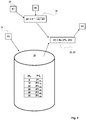
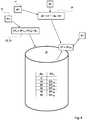
- the idealized error of the travel speed resulting from the route information results from twice the amount of the measurement error divided by the time interval. From this it can be seen that the resulting error becomes large with a small time interval since the measurement error of the track information remains system-conditioned.
- the error resulting from the time delay is calculated approximately from the multiplication of the acceleration and the half time interval. As a result, the resulting error changes according to the product of acceleration and time interval. Optimally, the time interval is accordingly chosen such that the sum of the errors becomes minimal.
- the first movement detection module shortens the time interval with increasing acceleration, or it extends the time interval with decreasing acceleration.
- the optimum time interval corresponds to an interval at which an error from the route information becomes equal to the error from the time delay.
- the first adjusted movement amount determined by the movement detection modules is a first travel speed, a first travel path or a first position of the elevator car
- the motion detection module uses at least one sensor for detecting the first travel speed of the first Travel path or the first position of the elevator car in the lift shaft. If necessary, of course, further adjusted quantities of movement can be determined on the basis of the detected movement quantity.
- the movement module detects the travel path and uses this movement variable to determine the travel speed.
- Other embodiments record, for example, the position of the elevator car in the lift shaft and determine on the basis of this amount of movement the track and the vehicle speed. The choice of the optimal design results from the availability or choice of sensors for detecting the amount of movement of the elevator car.
- the motion monitoring system includes a second motion detection module for determining a second adjusted motion magnitude in a second time interval.
- the second movement detection module determines the second time interval for determining the adjusted movement variable of the elevator car as a function of the first acceleration of the elevator car detected by the first acceleration sensor.
- the second movement detection module can also directly take over the first time interval provided by the first movement detection module as the second time interval.
- the second movement detection module it is of course also possible for the second movement detection module to determine the second time interval for determining the second adjusted movement variable of the elevator car as a function of a second acceleration of the elevator car detected by a second acceleration sensor.
- the movement of the elevator car is detected twice with independent modules and possibly also independent sensors. Failure or failure of a module or a sensor can thus be detected.
- the security of the device for monitoring the movement of the elevator car is improved.
- the motion monitoring system for monitoring the movement of the elevator car, the determined, first or second adjusted amount of movement, for example, the first or second speed and the first or second position of the elevator car in the elevator shaft, to an elevator control of the elevator system on.
- the elevator controller includes a travel controller that controls the drive of the elevator system accordingly to follow a predetermined driving profile.
- the motion monitoring system compares Furthermore, the determined, first or second adjusted amount of movement, for example, the first or second driving speed, with a limit speed and triggers a safety measure when exceeding the limit speed.
- the limit speed is provided, for example, in a cruising computer.
- the driving curve computer determines a first and possibly second or further limit speed permissible for a corresponding driving position of the elevator car in the shaft. If they are exceeded, a level-appropriate safety measure is triggered.
- the limit speeds may also be specified as fixed values.
- the motion monitoring system is set, for example, at the supplier to these fixed values.
- the sensor or sensors of the motion detection module detects an absolute position of the elevator car in the lift shaft.
- an absolute position system operates, for example, with sensors which record a magnetic, an optical, an acoustic or an electrical signal and which interact with appropriately designed signal generators, signal carriers and / or signal reflectors.
- a magnetic system operates, for example, with a magnetic belt arranged in the driving shaft, which has a magnetic coding. Based on the coding positions can be learned, stored and then recognized. The route information for determining corresponding quantities of motion then results from the difference between successive absolute positions.
- an optical system uses lasers which detect a distance to a reference point or it works with image patterns captured by an imager.
- image coding is used here, wherein the image information may be specially arranged images, such as a bar code, or a random, arbitrary image structure may be used.
- the route information, or the amount of movement can also be determined by comparing successive images.
- the image sequence is selected overlapping.
- a local displacement of any desired mark or a picture pattern between two or more images can be measured and accordingly a differential path can be determined.
- An acoustic system for example, uses an ultrasonic sensor to detect a distance to a reference point or an electrical system operates by means of position switches or detects a distance-dependent resistance in a measuring wire.
- components of the motion monitoring system are divided into two functional groups or functional units which operate essentially autonomously.
- a first functional unit comprises, for example, the first motion detection module, with sensor, processor, comparators, etc., and the first acceleration sensor.
- a second functional unit is accordingly formed by the second motion detection module, of course with a required sensor, processor, comparators, etc., and the second acceleration sensor.
- the comparators of the respective motion detection module or the respective function group compare the corresponding signals, such as the first and second cap positions, the first and second driving speeds, etc., of the other functional unit with the corresponding signals of the own functional unit, and output a warning signal, if a relevant deviation is found.
- the comparator is arranged independently of the first or second functional unit in the motion monitoring system. In this embodiment, he compares signals and / or intermediate results of the first and the second functional unit with each other and outputs the warning signal if relevant deviations between the two functional units are detected.
- This motion monitoring system is particularly safe and can be used for example as a safe alternative to a conventional mechanical speed limiter.
- the motion monitoring system has an event or data memory.
- this event or data store holds special events, and detected, adjusted motion quantities that led to that event are stored.
- adjusted quantities of motion are generally stored for a predetermined period of time. This allows mistakes to be understood or systematic differences, for example between the Motion detection modules can be detected and eliminated accordingly. If necessary, service messages are generated if systematic differences are detected between the individual motion detection modules.
- Systematic differences are, for example, constant absolute or relative differences.
- the output of a warning signal causes in one embodiment of the proposed solution, a shutdown of the elevator car.
- a current drive command or a pending Fahrablauf is completed properly and then the elevator car is stopped by switching off the drive motor and pressing the elevator brake.
- This overall makes possible a safe, efficient and pleasant operation of the elevator installation.
- An internal error of the motion monitoring system can thus be detected by the motion monitoring system for detecting a traveling path of the elevator car itself, and the elevator system can be repaired by a service technician.
- the proper closing of a possibly present driving command prevents people from being trapped in a suddenly stationary elevator car.
- the triggering of the safety measure in a first stage causes an interruption of a safety circuit, whereby the elevator car is stopped by normal resources.
- the safety circuit monitors safety-relevant functions of the elevator.
- An interruption of the safety circuit usually leads to an immediate shutdown of the elevator drive and to an actuation of the drive brake.
- the triggering of the safety measure causes an activation of an emergency braking device, whereby a stop of the elevator car takes place even in case of failure of the normal resources.
- emergency braking device for example, a safety gear is used, which is able to decelerate the elevator car on guide rails even in the event of failure of suspension elements.
- the motion-monitoring system for monitoring the movement of the elevator car is executed, for example, to subsequently initialize a plurality of safety measures following an unexpected increase in the driving speed.
- a drive control is instructed to reduce a driving speed as a first safety measure and to reduce it immediately to stop a next floor.
- the previously mentioned safety circuit is opened as a second safety measure and the drive brake is actuated immediately, which leads to an immediate stop of the elevator car.
- a further limit value is exceeded, the safety device is actuated directly as a further safety measure and the elevator car is clamped by the safety gear to the guide rails.
- the motion monitoring system for monitoring the movement of the elevator car further includes crash monitoring.
- a tearing of a cabin suspension can be detected quickly, since then the acceleration of the elevator car increases to a free fall value.
- the elevator car can be collected and clamped to the guide rails.
- FIG. 1 shows an elevator system 1 in an overall view.
- the elevator installation 1 is installed in a building and serves to transport persons or goods within the building.
- the elevator installation includes an elevator car 2, which can move up and down along guide rails 6.
- a drive 5 is used to drive and hold the elevator car 2.
- the drive 5 is arranged, for example, in the upper region of the building and the car 2 is suspended with support means 4, such as suspension ropes or carrying strap on the drive 5.
- the drive is usually made of a blowing zone 5.3 for driving the support means 4, a motor 5.1 for driving the blowing zone 5.3 and a drive brake 5.2 for holding the drive in a resting state.
- the support means 4 are guided via the drive 5, or, the blowing zone 5.3 on to a counterweight 3.
- the counterweight 3 compensates for a mass fraction of the elevator car 2, so that the drive 5 has to compensate for the main thing only an imbalance between the car 2 and counterweight 3.
- the drive 5 is arranged in the example in the upper part of the building. It could, of course, also be arranged at another location in the building, or in the area of the car 2 or the counterweight 3. Other versions of the drive are also possible.
- the drive brake 5.2 can also be arranged on the car 2, separated from the drive 5, or the drive 5 can directly drive the car 2.
- the elevator installation 1 is controlled by an elevator control 10.
- the elevator control 10 accepts user requests, optimizes the operation of the elevator installation and controls, usually via a drive control 10.1 the drive 5.
- the drive control 10.1 can be assembled with the elevator control 10, but it can also be arranged separately from the elevator control.
- the elevator control 10 also monitors a safety condition of the elevator installation and interrupts the operation when an unsafe operating condition occurs. This monitoring is usually performed using a safety circuit 40, in which all safety-related functions are involved.
- the elevator car 2 and, if necessary, the counterweight 3 is further equipped with a braking system which is suitable for securing and / or decelerating the elevator car 2 during an unexpected movement or at overspeed.
- the brake system includes safety brakes or safety gear 13, which are mounted on the vehicle body 2, 3.
- the safety brakes 13 are arranged in the example below the car 2 and they are electrically controlled by a brake control 41.
- the signals required for the control can be exchanged via wired signal lines or they can of course also be transmitted wirelessly.
- the Brake control 41 is connected to a motion monitoring module 11, which monitors the travel movements of the elevator car 2.
- the movement monitoring module 11 detects and determines relevant quantities of movement of the elevator car and forwards these quantities to the elevator control 10 or triggers any necessary safety measures.
- the motion-monitoring module 11 cooperates with a signal band 9, which allows detection of the position of the elevator car in the elevator shaft and the motion-monitoring module 11 initializes if necessary necessary safety measures.
- a mechanical speed limiter as it is commonly used, is unnecessary.
- FIG. 2 shows the elevator system of FIG. 1 in a schematic plan view.
- the brake system includes the two safety brakes 13.
- the two safety brakes 13 are preferably constructed identical or mirror-symmetrical and they act on the arranged on both sides of the car 2 brake rails.
- the brake rails are identical to the guide rails 6 in the example.
- the motion monitoring module 11 is in the embodiment according to Fig. 3 from a first motion detection module 20 and a second motion detection module 30 and the motion monitoring module 11 is accordingly carried out redundantly in important functions.
- Both movement modules 20, 30 include a first and a second sensor 21, 31 which cooperates in the example with a signal carrier 9.
- the signal carrier 9 is attached to a guide rail 6 and it includes in this embodiment, a magnetic coding.
- This magnetic coding includes a plurality of code marks arranged in a row, which are magnetized as either a south pole or a north pole. Several consecutive code marks form a codeword.
- the code words in turn are arranged in a row as a code mark pattern with binary pseudorandom coding. Each code word represents an absolute cabin position in the elevator shaft.
- the first movement detection module 20 thus includes the first sensor 21 or a group of individual sensors, preferably Hall elements, with associated evaluation logic and memories.
- the first sensor 21 detects the code marks and determines the current one first car position P1 t at short intervals dt n , or with a corresponding sampling rate. Such an interval is for example 10 milliseconds.
- the cabin positions P1 t detected in this way are forwarded, on the one hand, directly to the elevator control 10 as the first adjusted cabin position P1 and, on the other hand, stored in a memory 29. In memory 29, as in FIG.
- the first motion detection module 20 now further includes a first acceleration sensor 24 that detects a current first acceleration A1 of the elevator car.
- An acceleration calculator 25 determines, on the basis of the system-related accuracy ds, the position detection and the current first acceleration A1, an optimum first time interval dt1 for determining a first adjusted movement amount S1, V1 of the elevator car.
- a route computer 22 and a speed calculator 23 now use the corresponding previous cabin positions P1_t on the basis of the optimal first time interval dt1 and determine the first adjusted motion quantities S1, V1.
- the thus determined first adjusted movement quantity V1 is now likewise made available to the elevator control 10 for controlling and regulating the elevator.
- the evaluation of the aforementioned data takes place in time steps corresponding to the first time interval dt1.
- a typical maximum first time interval dt1 which is used to determine the first adjusted movement quantities V1, with an accuracy of the position detection of about 0.5 millimeters, of the order of 30 to 50 milliseconds.
- the intermediate storage in the memory 29 accordingly comprises at least the cabin positions corresponding to the maximum time interval. With increasing acceleration, this time interval can be reduced to up to 10 milliseconds. Accordingly, a time error can be reduced to about 5 milliseconds. Particularly useful is such a reduction of the time interval at acceleration ranges above about 0.5g (half gravitational acceleration), since such accelerations do not occur in normal operation and such accelerations quickly lead to high speeds.
- the first movement detection module 20 according to FIG. 3 an optional monitoring unit 26 which compares the first adjusted vehicle speed V1 with one or more limit speeds VG. Upon detection of an exceeding of these limits, the safety circuit 40 is interrupted and thus the drive 5 is stopped or it is, for example via a brake control 41, a safety brake 13 is actuated.
- the first movement detection module 20 further includes a crash monitoring device 27. The crash monitoring device 27 compares the first acceleration A1 with an acceleration limit value AG and, if necessary, actuates the safety brake 13 via the brake control 41.
- the present movement monitoring module 11 now comprises according to FIG. 3 the second motion detection module 30, which includes the first sensor 21 redundant second sensor 31 to improve the reliability of the system.
- the second sensor 31 detects the code marks of the signal carrier 9 and determines a current second cabin position P2, which should correspond in principle to the first car position P1.
- a path calculator 32 determines path increments or a traveled second travel path S2 from consecutive second car positions, and a second speed calculator 33 determines a second driving speed V2 from the traveled second travel path S2.
- the mode of operation with detection and intermediate storage of the car positions corresponds analogously to the explanations as previously explained in the case of the first movement detection module 20.
- the second movement detection module 30 obtains the first time interval dt1 for detecting or determining the adjusted second movement variable P2, S2, V2 from the first movement module 20. Furthermore, the second movement detection module 30 also includes a monitoring unit 36 which determines the second travel speed V2 compares with one or more limit speeds VG. Upon detection of exceeding these limits, or the limit speeds VG, the safety circuit 40 is interrupted and thus the
- the first movement module 20 adopts the second adjusted movement quantities P2, V2 detected by the second movement detection module 30 and compares in a comparator 28 the corresponding values with the first adjusted movement quantities P1, V1 of the first movement module 20. If the comparison shows a match of the adjusted movement quantities P1 / P2, V1 / V2 results, an okay status is output. If the comparison results in no match of the adjusted movement variables, the elevator drive, for example, by interrupting the safety circuit 40 or by a corresponding warning level 42, which is delivered to the elevator or drive control 10, 10.1, stopped.
- the two movement modules 20, 30 are preferably arranged in a common housing and can be arranged as a unit on the elevator car 2 and aligned with the signal carrier 9.
- the individual computers 22, 23, 25, comparators 28 and monitoring units 26, 27 as well as the acceleration sensor 24 may at most be assembled with the sensor 21 on common boards or the computing functions may be combined in common processors.
- the two movement modules 20, 30 are designed with redundant sensors 21, 31 for detecting adjusted quantities of motion and with redundant processors for evaluating the sensor signals.
- the second movement module 30 uses the first time interval dt1 determined by the first movement module 20.
- the first time interval dt1 thus also corresponds at the same time to a second time interval dt2.
- the motion monitoring module 11 again consists of a first motion detection module 20 and a second motion detection module 30.
- the first motion detection module 20 essentially corresponds to the embodiment, as described in connection with FIG FIG. 3 was explained. Again, the first car positions P1 t detected at short intervals dt n , or at a corresponding sampling rate, become current first adjusted cabin position P1 forwarded directly to the elevator control 10. In contrast to the embodiment of FIG.
- these values in the buffer memory 29 are overwritten again with each subsequent position.
- the acceleration calculator 25 determines the optimum time interval dt for determining the first adjusted movement quantity S1, V1 of the elevator car.
- the movement detection module 20 retrieves the first provisional movement variable associated with the corresponding optimum time interval, or the first provisional travel speed V1 _n , from the memory 29 and outputs them directly to the elevator control 10 as the first adjusted movement variable.
- the motion monitoring module 11 also includes the motion monitoring module 11 according to the embodiment of FIG.
- the monitoring unit 26 which compares the first adjusted driving speed V1 with one or more limit speeds VG and which interrupts the safety circuit 40 upon detection of an exceeding of these limit values or limit speeds VG and thus stops the drive 5 or via a brake control 41 a safety brake 13 actuated.
- the first movement detection module 20 further includes the crash monitoring device 27, which compares the measured first acceleration A1 with an acceleration limit value AG and, if necessary, actuates the safety brake 13 via the brake control 41.
- Both movement modules 20, 30 thus include at least one of the sensors 21, 31 which cooperate with the signal carrier 9 and which determine the current provisional cabin positions P1, P2 independently of one another.
- Path calculator 22, 32 determine from successive cabin positions Weginkremente or Travel distances S1, S2 and independent speed calculators 23, 33 ascertain traveling speeds V1, V2 corresponding to the travel route information S1, S2 and store these results in corresponding memories 29, 39.
- the aforementioned data are acquired at short time intervals and the determination or determination of the data first and second adjusted quantities of motion take place at optimal time intervals dt.
- both movement modules 20, 30 include acceleration sensors 24, 34, which detect the current first and second accelerations A1, A2 of the elevator car.
- the acceleration calculators 25, 35 determine the optimum first and second time intervals dt1, dt2 for determining the adjusted motion quantities.
- Both motion detection modules 20, 30 further include monitoring units 26, 36 which compare the first and second driving speeds V1, V2 with one or more limit speeds VG. Upon detection of exceeding these limits, or limit speeds VG, the safety circuit 40 is interrupted by the brake modules 20, 30, independently of each other, and thus the drive 5 is stopped, or it is, again independently, via the brake control 41, the safety brake 13 is actuated , As a result, safety is greatly increased since limit values are recorded, evaluated and assessed by two separate systems, and likewise required measures are activated separately.
- both motion detection modules 20, 30 also each include a crash monitor 27, 37, wherein the measured first and second accelerations A1, A2 are compared with an acceleration threshold AG and on detection of an excessive acceleration value (A1 or A2 greater AG) the brake control 41 directly the safety brake 13 is actuated.
- both movement modules 20, 30 include a comparator 28, 38, which compares a first signal F1 of the first movement module 20 with a second signal F2 of the second movement module 30.
- the first comparator 28 of the first movement module 20 compares the second signals F2 detected by the second movement detection module 30, such as the second movement quantities P2, V2, as well as the second movement quantities P2 second acceleration A2 with the corresponding own first signals F1, such as the first motion quantities P1, V1 and the first acceleration A1.
- the second comparator 38 of the second movement module 30 compares the first signals F1 detected by the first movement detection module 20 with the corresponding own second signals F2.
- Both comparators 28, 38 generate a warning level 42 when a relevant deviation between the corresponding first and second signals F1, F2, or the values P1 / P2, S1 / S2, V1 / V2, A1 / A2 is detected. Interim results, such as the time intervals dt1, dt2 or calculated path increments, etc., can also be included in the comparison.
- the elevator control 10 is instructed to complete the current drive and then to stop the elevator.
- both movement modules 20, 30 can trigger any necessary safety measures, safety is still given since a simultaneous failure of both movement modules is unlikely.
- the two movement modules 20, 30 are constructed as separate functional groups 20a, 30a. This means that the functional groups 20a, 30a basically operate autonomously, for example have their own energy resources and can be tested independently, for example, in production.
- One of the two movement modules 20, 30, or one of the two functional groups 20a, 30a is determined as a master. In the present example, this is the movement module 20.
- the movement module 20 provides the determined first movement quantities P1, V1 of the elevator control for travel control.
- the signal carrier 9 can be divided into two redundant carrier.
- the functional groups 20a, 30a according to FIG. 5 can analogously to the design of FIG. 3 be divided into redundant processors and modules. They can also be joined together to form a function group.
- other systems such as an ultrasound-supported displacement measuring system, an image recognition system or a path measuring system with incremental encoders, etc., can be used. Different detection systems can also be combined.
- the first movement module 20 may operate with a magnetic code and the second movement module 30 may operate on the basis of ultrasound.
- the memory and computation architecture of the embodiments may be interchanged among the figures.
Landscapes
- Engineering & Computer Science (AREA)
- Automation & Control Theory (AREA)
- Physics & Mathematics (AREA)
- General Physics & Mathematics (AREA)
- Computer Networks & Wireless Communication (AREA)
- Mechanical Engineering (AREA)
- General Engineering & Computer Science (AREA)
- Maintenance And Inspection Apparatuses For Elevators (AREA)
- Electric Propulsion And Braking For Vehicles (AREA)
- Elevator Control (AREA)
- Indicating And Signalling Devices For Elevators (AREA)
Priority Applications (2)
| Application Number | Priority Date | Filing Date | Title |
|---|---|---|---|
| PL13779611T PL2914529T3 (pl) | 2012-10-30 | 2013-10-22 | System monitorowania ruchu instalacji dźwigowej |
| EP13779611.6A EP2914529B1 (de) | 2012-10-30 | 2013-10-22 | Bewegungs-überwachungssystem einer aufzugsanlage |
Applications Claiming Priority (3)
| Application Number | Priority Date | Filing Date | Title |
|---|---|---|---|
| EP12190499 | 2012-10-30 | ||
| PCT/EP2013/072062 WO2014067814A1 (de) | 2012-10-30 | 2013-10-22 | Bewegungs-überwachungssystem einer aufzugsanlage |
| EP13779611.6A EP2914529B1 (de) | 2012-10-30 | 2013-10-22 | Bewegungs-überwachungssystem einer aufzugsanlage |
Publications (2)
| Publication Number | Publication Date |
|---|---|
| EP2914529A1 EP2914529A1 (de) | 2015-09-09 |
| EP2914529B1 true EP2914529B1 (de) | 2016-12-14 |
Family
ID=47142965
Family Applications (1)
| Application Number | Title | Priority Date | Filing Date |
|---|---|---|---|
| EP13779611.6A Active EP2914529B1 (de) | 2012-10-30 | 2013-10-22 | Bewegungs-überwachungssystem einer aufzugsanlage |
Country Status (7)
| Country | Link |
|---|---|
| US (1) | US9926170B2 (pl) |
| EP (1) | EP2914529B1 (pl) |
| CN (1) | CN104768862B (pl) |
| BR (1) | BR112015007078B1 (pl) |
| ES (1) | ES2619637T3 (pl) |
| PL (1) | PL2914529T3 (pl) |
| WO (1) | WO2014067814A1 (pl) |
Families Citing this family (24)
| Publication number | Priority date | Publication date | Assignee | Title |
|---|---|---|---|---|
| DE102014113341A1 (de) * | 2014-09-16 | 2016-03-17 | Manfred Lienemann | Verfahren zum Betrieb einer Aufzuganlage und Aufzuganlage für Personen und/oder Lasten |
| DE102014118293A1 (de) * | 2014-12-10 | 2016-06-16 | Océ Printing Systems GmbH & Co. KG | System und Verfahren zur Überwachung eines Produktionssystems |
| CN105129560A (zh) * | 2015-10-15 | 2015-12-09 | 上海斐讯数据通信技术有限公司 | 一种电梯的安全监测方法、监测系统及移动终端 |
| ES2748521T3 (es) * | 2015-12-02 | 2020-03-17 | Inventio Ag | Supervisión y/o establecimiento de protocolos de una posición de una herramienta en una caja de ascensor |
| EP3257799B1 (en) * | 2016-06-17 | 2022-02-23 | KONE Corporation | Redundant safety circuit |
| CN106645800A (zh) * | 2016-11-22 | 2017-05-10 | 耿龙 | 一种电梯测速器检测装置的检测方法 |
| CN110799436B (zh) | 2017-06-27 | 2022-06-17 | 因温特奥股份公司 | 位置确定系统和用于获取电梯轿厢的轿厢位置的方法 |
| CN109279466B (zh) * | 2017-07-21 | 2021-08-17 | 奥的斯电梯公司 | 电梯乘客的异常移动的自动检测 |
| US11434104B2 (en) * | 2017-12-08 | 2022-09-06 | Otis Elevator Company | Continuous monitoring of rail and ride quality of elevator system |
| CN108333967B (zh) * | 2018-02-05 | 2021-01-29 | 熵基科技股份有限公司 | 一种人行通道闸逻辑检测方法、系统及设备和存储介质 |
| US12459780B2 (en) * | 2018-06-27 | 2025-11-04 | Inventio Ag | Method and system for determining the position of an elevator car of an elevator installation |
| DE102018214251B3 (de) * | 2018-08-23 | 2020-01-09 | Thyssenkrupp Ag | Aufzugsanlage |
| EP3632830B1 (en) | 2018-10-04 | 2024-03-20 | Otis Elevator Company | Elevator car position determination |
| EP3663248B1 (en) | 2018-12-03 | 2022-05-11 | Otis Elevator Company | Device and method for monitoring an elevator system |
| US11591183B2 (en) | 2018-12-28 | 2023-02-28 | Otis Elevator Company | Enhancing elevator sensor operation for improved maintenance |
| EP3990378B1 (en) * | 2019-06-28 | 2023-12-27 | Inventio Ag | Method and device for determining multiple absolute cabin positions of an elevator cabin within a shaft of an elevator arrangement |
| US12139370B2 (en) * | 2019-09-27 | 2024-11-12 | Otis Elevator Company | Air pressure and acceleration sensor floor correction by elevator status information |
| EP3892579A1 (en) * | 2020-04-06 | 2021-10-13 | Otis Elevator Company | Elevator safety systems |
| CN112408123B (zh) * | 2020-11-16 | 2023-03-31 | 日立楼宇技术(广州)有限公司 | 电梯控制系统、方法、装置、计算机设备和存储介质 |
| CN112693989A (zh) * | 2020-12-28 | 2021-04-23 | 福建省特种设备检验研究院泉州分院 | 一种基于大数据的电梯检测方法 |
| CN113651204B (zh) * | 2021-08-30 | 2022-10-11 | 浙江省特种设备科学研究院 | 一种空载补偿法电梯渐进式安全钳检测方法及装置 |
| CN113879928B (zh) * | 2021-09-27 | 2023-04-21 | 山东电力建设第三工程有限公司 | 一种施工升降机标准节轨道状态监测方法 |
| IT202100025265A1 (it) * | 2021-10-01 | 2023-04-01 | Zetaplan S R L | Metodo di rilevazione guasti per un impianto ascensore, dispositivo di rilevazione guasti, kit di rilevazione guasti, impianto ascensore |
| CN115535780A (zh) * | 2022-09-16 | 2022-12-30 | 上海三菱电梯有限公司 | 轿厢制动系统及电梯 |
Family Cites Families (12)
| Publication number | Priority date | Publication date | Assignee | Title |
|---|---|---|---|---|
| US6173813B1 (en) * | 1998-12-23 | 2001-01-16 | Otis Elevator Company | Electronic control for an elevator braking system |
| TW575518B (en) | 2001-07-31 | 2004-02-11 | Inventio Ag | Lift installation with a measuring system for determining absolute cage position |
| DE102004009250A1 (de) * | 2004-02-20 | 2005-09-08 | K.A. Schmersal Holding Kg | Sicherheitsüberwachungseinrichtung für eine Aufzugskabine |
| EP1602610B1 (en) | 2004-06-02 | 2010-04-14 | Inventio Ag | Elevator supervision |
| FI119508B (fi) | 2007-04-03 | 2008-12-15 | Kone Corp | Vikaturvallinen tehonohjauslaitteisto |
| DE102007034031A1 (de) | 2007-07-20 | 2009-01-22 | Robert Bosch Gmbh | Verfahren zur Bestimmung einer Ähnlichkeit, Vorrichtung und Verwendung hierfür |
| JP4812037B2 (ja) | 2007-07-23 | 2011-11-09 | 株式会社日立製作所 | エレベーター乗りかごの速度検出装置およびエレベーターの安全装置 |
| JP2012520811A (ja) | 2009-03-16 | 2012-09-10 | オーチス エレベータ カンパニー | 過加速度および過速度検出・処理システム |
| CN202063717U (zh) | 2011-05-27 | 2011-12-07 | 广州气虹空气分离设备有限公司 | 一种中低纯度小型制氮机 |
| CN202063617U (zh) * | 2011-06-02 | 2011-12-07 | 恒达富士电梯有限公司 | 一种电梯监控系统 |
| CN104718148B (zh) * | 2012-10-18 | 2016-10-12 | 因温特奥股份公司 | 电梯设备的安全装置 |
| DE112012007228T5 (de) * | 2012-12-17 | 2015-09-24 | Mitsubishi Electric Corporation | Aufzugvorrichtung |
-
2013
- 2013-10-22 ES ES13779611.6T patent/ES2619637T3/es active Active
- 2013-10-22 US US14/439,264 patent/US9926170B2/en active Active
- 2013-10-22 CN CN201380056721.8A patent/CN104768862B/zh active Active
- 2013-10-22 EP EP13779611.6A patent/EP2914529B1/de active Active
- 2013-10-22 PL PL13779611T patent/PL2914529T3/pl unknown
- 2013-10-22 WO PCT/EP2013/072062 patent/WO2014067814A1/de not_active Ceased
- 2013-10-22 BR BR112015007078-7A patent/BR112015007078B1/pt not_active IP Right Cessation
Also Published As
| Publication number | Publication date |
|---|---|
| BR112015007078A2 (pt) | 2017-07-04 |
| US20150307319A1 (en) | 2015-10-29 |
| ES2619637T3 (es) | 2017-06-26 |
| CN104768862A (zh) | 2015-07-08 |
| HK1210131A1 (en) | 2016-04-15 |
| EP2914529A1 (de) | 2015-09-09 |
| WO2014067814A1 (de) | 2014-05-08 |
| CN104768862B (zh) | 2016-11-16 |
| PL2914529T3 (pl) | 2017-06-30 |
| BR112015007078B1 (pt) | 2021-02-23 |
| US9926170B2 (en) | 2018-03-27 |
Similar Documents
| Publication | Publication Date | Title |
|---|---|---|
| EP2914529A1 (de) | Bewegungs-überwachungssystem einer aufzugsanlage | |
| EP2807103B1 (de) | Verfahren und steuereinrichtung zur überwachung von fahrbewegungen einer aufzugskabine | |
| EP3317218B1 (de) | Überwachungsvorrichtung und überwachungsverfahren für eine aufzugsanlage | |
| EP2516305B1 (de) | Verfahren und vorrichtung zur bestimmung der bewegung und/oder der position einer aufzugskabine | |
| EP2909122B1 (de) | Sicherheitseinrichtung einer aufzugsanlage | |
| EP3559505B1 (de) | Systeme zur überwachung des betriebs einer energieführungskette | |
| EP0391174B2 (de) | Vorrichtung und Verfahren zum Erfassen von physikalischen Kenngrössen eines Aufzuges | |
| EP2170753B1 (de) | Aufzugsanlage mit einer aufzugkabine und einer bremseinrichtung zum stillsetzen der aufzugkabine im sonderbetrieb und ein verfahren zum stillsetzen einer aufzugkabine im sonderbetrieb | |
| US7946393B2 (en) | Safety evaluation and control system for elevator units | |
| EP1953062B1 (de) | Vorrichtung und Verfahren zur Seillageüberwachung einer seilbetriebenen Transportanlage | |
| DE112013006482T5 (de) | Aufzugsvorrichtung | |
| DE10304019A1 (de) | Verfahren zum Überwachen einer Maschine und derartige Maschine, insbesondere Roboter | |
| EP3883807A1 (de) | Verfahren zum sicheren überwachen der funktion einer elektromagnetischen transporteinrichtung | |
| EP2218624A2 (de) | Radsensor, Eisenbahnanlage mit zumindest einem Radsensor sowie Verfahren zum Betreiben einer Eisenbahnanlage | |
| EP2567923A1 (de) | Redundante Schachtkopierung | |
| WO2009013114A1 (de) | Verfahren zur ermittlung der geschwindigkeit einer aufzugskabine und eine steuereinheit zur durchführung dieses verfahrens | |
| EP3559504A1 (de) | Überwachungssystem für den betrieb einer energieführungskette | |
| EP3924240B1 (de) | Anlage mit auf einer verfahrfläche der anlage bewegbarem mobilteil | |
| DE102004058471A1 (de) | Sicherheitseinrichtung für eine automatisiert arbeitende Anlage mit zumindest einem automatisiert bewegbaren Anlagenteil | |
| DE102016125196A1 (de) | Verfahren zur Entgleisungsdetektion anhand von Raddrehzahlsignalen | |
| DE202016101183U1 (de) | Aufzug mit einem Sicherheitscontroller zum unmittelbaren Beeinflussen der Bremskraft | |
| EP2701962A1 (de) | Schienenfahrzeug mit einer heissläuferüberwachung | |
| EP1516842A2 (de) | Steuerungs- und Regelungseinrichtung für einen Aufzug | |
| EP3963291B1 (de) | Sensoranordnung zum überwachen eines technischen systems und verfahren zum betreiben einer sensoranordnung | |
| HK1210131B (en) | Movement-monitoring system of a lift installation |
Legal Events
| Date | Code | Title | Description |
|---|---|---|---|
| PUAI | Public reference made under article 153(3) epc to a published international application that has entered the european phase |
Free format text: ORIGINAL CODE: 0009012 |
|
| 17P | Request for examination filed |
Effective date: 20150303 |
|
| AK | Designated contracting states |
Kind code of ref document: A1 Designated state(s): AL AT BE BG CH CY CZ DE DK EE ES FI FR GB GR HR HU IE IS IT LI LT LU LV MC MK MT NL NO PL PT RO RS SE SI SK SM TR |
|
| AX | Request for extension of the european patent |
Extension state: BA ME |
|
| DAX | Request for extension of the european patent (deleted) | ||
| GRAP | Despatch of communication of intention to grant a patent |
Free format text: ORIGINAL CODE: EPIDOSNIGR1 |
|
| INTG | Intention to grant announced |
Effective date: 20160607 |
|
| GRAS | Grant fee paid |
Free format text: ORIGINAL CODE: EPIDOSNIGR3 |
|
| GRAA | (expected) grant |
Free format text: ORIGINAL CODE: 0009210 |
|
| AK | Designated contracting states |
Kind code of ref document: B1 Designated state(s): AL AT BE BG CH CY CZ DE DK EE ES FI FR GB GR HR HU IE IS IT LI LT LU LV MC MK MT NL NO PL PT RO RS SE SI SK SM TR |
|
| REG | Reference to a national code |
Ref country code: GB Ref legal event code: FG4D Free format text: NOT ENGLISH |
|
| REG | Reference to a national code |
Ref country code: CH Ref legal event code: EP |
|
| REG | Reference to a national code |
Ref country code: IE Ref legal event code: FG4D Free format text: LANGUAGE OF EP DOCUMENT: GERMAN |
|
| REG | Reference to a national code |
Ref country code: AT Ref legal event code: REF Ref document number: 853361 Country of ref document: AT Kind code of ref document: T Effective date: 20170115 |
|
| REG | Reference to a national code |
Ref country code: DE Ref legal event code: R096 Ref document number: 502013005769 Country of ref document: DE |
|
| PG25 | Lapsed in a contracting state [announced via postgrant information from national office to epo] |
Ref country code: LV Free format text: LAPSE BECAUSE OF FAILURE TO SUBMIT A TRANSLATION OF THE DESCRIPTION OR TO PAY THE FEE WITHIN THE PRESCRIBED TIME-LIMIT Effective date: 20161214 |
|
| REG | Reference to a national code |
Ref country code: NL Ref legal event code: FP |
|
| REG | Reference to a national code |
Ref country code: SE Ref legal event code: TRGR |
|
| REG | Reference to a national code |
Ref country code: LT Ref legal event code: MG4D |
|
| PG25 | Lapsed in a contracting state [announced via postgrant information from national office to epo] |
Ref country code: NO Free format text: LAPSE BECAUSE OF FAILURE TO SUBMIT A TRANSLATION OF THE DESCRIPTION OR TO PAY THE FEE WITHIN THE PRESCRIBED TIME-LIMIT Effective date: 20170314 Ref country code: GR Free format text: LAPSE BECAUSE OF FAILURE TO SUBMIT A TRANSLATION OF THE DESCRIPTION OR TO PAY THE FEE WITHIN THE PRESCRIBED TIME-LIMIT Effective date: 20170315 Ref country code: LT Free format text: LAPSE BECAUSE OF FAILURE TO SUBMIT A TRANSLATION OF THE DESCRIPTION OR TO PAY THE FEE WITHIN THE PRESCRIBED TIME-LIMIT Effective date: 20161214 |
|
| PG25 | Lapsed in a contracting state [announced via postgrant information from national office to epo] |
Ref country code: HR Free format text: LAPSE BECAUSE OF FAILURE TO SUBMIT A TRANSLATION OF THE DESCRIPTION OR TO PAY THE FEE WITHIN THE PRESCRIBED TIME-LIMIT Effective date: 20161214 Ref country code: RS Free format text: LAPSE BECAUSE OF FAILURE TO SUBMIT A TRANSLATION OF THE DESCRIPTION OR TO PAY THE FEE WITHIN THE PRESCRIBED TIME-LIMIT Effective date: 20161214 |
|
| REG | Reference to a national code |
Ref country code: ES Ref legal event code: FG2A Ref document number: 2619637 Country of ref document: ES Kind code of ref document: T3 Effective date: 20170626 |
|
| PG25 | Lapsed in a contracting state [announced via postgrant information from national office to epo] |
Ref country code: IS Free format text: LAPSE BECAUSE OF FAILURE TO SUBMIT A TRANSLATION OF THE DESCRIPTION OR TO PAY THE FEE WITHIN THE PRESCRIBED TIME-LIMIT Effective date: 20170414 Ref country code: RO Free format text: LAPSE BECAUSE OF FAILURE TO SUBMIT A TRANSLATION OF THE DESCRIPTION OR TO PAY THE FEE WITHIN THE PRESCRIBED TIME-LIMIT Effective date: 20161214 Ref country code: EE Free format text: LAPSE BECAUSE OF FAILURE TO SUBMIT A TRANSLATION OF THE DESCRIPTION OR TO PAY THE FEE WITHIN THE PRESCRIBED TIME-LIMIT Effective date: 20161214 Ref country code: SK Free format text: LAPSE BECAUSE OF FAILURE TO SUBMIT A TRANSLATION OF THE DESCRIPTION OR TO PAY THE FEE WITHIN THE PRESCRIBED TIME-LIMIT Effective date: 20161214 |
|
| PG25 | Lapsed in a contracting state [announced via postgrant information from national office to epo] |
Ref country code: PT Free format text: LAPSE BECAUSE OF FAILURE TO SUBMIT A TRANSLATION OF THE DESCRIPTION OR TO PAY THE FEE WITHIN THE PRESCRIBED TIME-LIMIT Effective date: 20170414 Ref country code: BG Free format text: LAPSE BECAUSE OF FAILURE TO SUBMIT A TRANSLATION OF THE DESCRIPTION OR TO PAY THE FEE WITHIN THE PRESCRIBED TIME-LIMIT Effective date: 20170314 Ref country code: SM Free format text: LAPSE BECAUSE OF FAILURE TO SUBMIT A TRANSLATION OF THE DESCRIPTION OR TO PAY THE FEE WITHIN THE PRESCRIBED TIME-LIMIT Effective date: 20161214 |
|
| REG | Reference to a national code |
Ref country code: DE Ref legal event code: R097 Ref document number: 502013005769 Country of ref document: DE |
|
| PLBE | No opposition filed within time limit |
Free format text: ORIGINAL CODE: 0009261 |
|
| STAA | Information on the status of an ep patent application or granted ep patent |
Free format text: STATUS: NO OPPOSITION FILED WITHIN TIME LIMIT |
|
| REG | Reference to a national code |
Ref country code: FR Ref legal event code: PLFP Year of fee payment: 5 |
|
| 26N | No opposition filed |
Effective date: 20170915 |
|
| PG25 | Lapsed in a contracting state [announced via postgrant information from national office to epo] |
Ref country code: DK Free format text: LAPSE BECAUSE OF FAILURE TO SUBMIT A TRANSLATION OF THE DESCRIPTION OR TO PAY THE FEE WITHIN THE PRESCRIBED TIME-LIMIT Effective date: 20161214 |
|
| PG25 | Lapsed in a contracting state [announced via postgrant information from national office to epo] |
Ref country code: SI Free format text: LAPSE BECAUSE OF FAILURE TO SUBMIT A TRANSLATION OF THE DESCRIPTION OR TO PAY THE FEE WITHIN THE PRESCRIBED TIME-LIMIT Effective date: 20161214 |
|
| PG25 | Lapsed in a contracting state [announced via postgrant information from national office to epo] |
Ref country code: MC Free format text: LAPSE BECAUSE OF FAILURE TO SUBMIT A TRANSLATION OF THE DESCRIPTION OR TO PAY THE FEE WITHIN THE PRESCRIBED TIME-LIMIT Effective date: 20161214 |
|
| REG | Reference to a national code |
Ref country code: IE Ref legal event code: MM4A |
|
| PG25 | Lapsed in a contracting state [announced via postgrant information from national office to epo] |
Ref country code: LU Free format text: LAPSE BECAUSE OF NON-PAYMENT OF DUE FEES Effective date: 20171022 |
|
| PG25 | Lapsed in a contracting state [announced via postgrant information from national office to epo] |
Ref country code: MT Free format text: LAPSE BECAUSE OF FAILURE TO SUBMIT A TRANSLATION OF THE DESCRIPTION OR TO PAY THE FEE WITHIN THE PRESCRIBED TIME-LIMIT Effective date: 20161214 |
|
| REG | Reference to a national code |
Ref country code: FR Ref legal event code: PLFP Year of fee payment: 6 |
|
| PG25 | Lapsed in a contracting state [announced via postgrant information from national office to epo] |
Ref country code: IE Free format text: LAPSE BECAUSE OF NON-PAYMENT OF DUE FEES Effective date: 20171022 |
|
| PG25 | Lapsed in a contracting state [announced via postgrant information from national office to epo] |
Ref country code: HU Free format text: LAPSE BECAUSE OF FAILURE TO SUBMIT A TRANSLATION OF THE DESCRIPTION OR TO PAY THE FEE WITHIN THE PRESCRIBED TIME-LIMIT; INVALID AB INITIO Effective date: 20131022 |
|
| PG25 | Lapsed in a contracting state [announced via postgrant information from national office to epo] |
Ref country code: CY Free format text: LAPSE BECAUSE OF FAILURE TO SUBMIT A TRANSLATION OF THE DESCRIPTION OR TO PAY THE FEE WITHIN THE PRESCRIBED TIME-LIMIT Effective date: 20161214 |
|
| PGFP | Annual fee paid to national office [announced via postgrant information from national office to epo] |
Ref country code: CZ Payment date: 20190925 Year of fee payment: 7 |
|
| PG25 | Lapsed in a contracting state [announced via postgrant information from national office to epo] |
Ref country code: MK Free format text: LAPSE BECAUSE OF FAILURE TO SUBMIT A TRANSLATION OF THE DESCRIPTION OR TO PAY THE FEE WITHIN THE PRESCRIBED TIME-LIMIT Effective date: 20161214 |
|
| PGFP | Annual fee paid to national office [announced via postgrant information from national office to epo] |
Ref country code: FI Payment date: 20191022 Year of fee payment: 7 Ref country code: SE Payment date: 20191021 Year of fee payment: 7 Ref country code: NL Payment date: 20191021 Year of fee payment: 7 |
|
| PGFP | Annual fee paid to national office [announced via postgrant information from national office to epo] |
Ref country code: ES Payment date: 20191126 Year of fee payment: 7 Ref country code: BE Payment date: 20191021 Year of fee payment: 7 Ref country code: IT Payment date: 20191028 Year of fee payment: 7 Ref country code: PL Payment date: 20191004 Year of fee payment: 7 |
|
| PGFP | Annual fee paid to national office [announced via postgrant information from national office to epo] |
Ref country code: AT Payment date: 20191022 Year of fee payment: 7 |
|
| PG25 | Lapsed in a contracting state [announced via postgrant information from national office to epo] |
Ref country code: AL Free format text: LAPSE BECAUSE OF FAILURE TO SUBMIT A TRANSLATION OF THE DESCRIPTION OR TO PAY THE FEE WITHIN THE PRESCRIBED TIME-LIMIT Effective date: 20161214 |
|
| REG | Reference to a national code |
Ref country code: FI Ref legal event code: MAE |
|
| REG | Reference to a national code |
Ref country code: SE Ref legal event code: EUG |
|
| REG | Reference to a national code |
Ref country code: NL Ref legal event code: MM Effective date: 20201101 |
|
| REG | Reference to a national code |
Ref country code: AT Ref legal event code: MM01 Ref document number: 853361 Country of ref document: AT Kind code of ref document: T Effective date: 20201022 |
|
| REG | Reference to a national code |
Ref country code: BE Ref legal event code: MM Effective date: 20201031 |
|
| PG25 | Lapsed in a contracting state [announced via postgrant information from national office to epo] |
Ref country code: FI Free format text: LAPSE BECAUSE OF NON-PAYMENT OF DUE FEES Effective date: 20201022 Ref country code: NL Free format text: LAPSE BECAUSE OF NON-PAYMENT OF DUE FEES Effective date: 20201101 Ref country code: CZ Free format text: LAPSE BECAUSE OF NON-PAYMENT OF DUE FEES Effective date: 20201022 |
|
| PG25 | Lapsed in a contracting state [announced via postgrant information from national office to epo] |
Ref country code: SE Free format text: LAPSE BECAUSE OF NON-PAYMENT OF DUE FEES Effective date: 20201023 Ref country code: BE Free format text: LAPSE BECAUSE OF NON-PAYMENT OF DUE FEES Effective date: 20201031 Ref country code: AT Free format text: LAPSE BECAUSE OF NON-PAYMENT OF DUE FEES Effective date: 20201022 |
|
| PG25 | Lapsed in a contracting state [announced via postgrant information from national office to epo] |
Ref country code: IT Free format text: LAPSE BECAUSE OF NON-PAYMENT OF DUE FEES Effective date: 20201022 |
|
| REG | Reference to a national code |
Ref country code: ES Ref legal event code: FD2A Effective date: 20220128 |
|
| PGFP | Annual fee paid to national office [announced via postgrant information from national office to epo] |
Ref country code: TR Payment date: 20211011 Year of fee payment: 9 Ref country code: GB Payment date: 20211026 Year of fee payment: 9 |
|
| PGFP | Annual fee paid to national office [announced via postgrant information from national office to epo] |
Ref country code: FR Payment date: 20211028 Year of fee payment: 9 |
|
| PG25 | Lapsed in a contracting state [announced via postgrant information from national office to epo] |
Ref country code: ES Free format text: LAPSE BECAUSE OF NON-PAYMENT OF DUE FEES Effective date: 20201023 |
|
| PG25 | Lapsed in a contracting state [announced via postgrant information from national office to epo] |
Ref country code: PL Free format text: LAPSE BECAUSE OF NON-PAYMENT OF DUE FEES Effective date: 20201022 |
|
| GBPC | Gb: european patent ceased through non-payment of renewal fee |
Effective date: 20221022 |
|
| PG25 | Lapsed in a contracting state [announced via postgrant information from national office to epo] |
Ref country code: FR Free format text: LAPSE BECAUSE OF NON-PAYMENT OF DUE FEES Effective date: 20221031 |
|
| PG25 | Lapsed in a contracting state [announced via postgrant information from national office to epo] |
Ref country code: GB Free format text: LAPSE BECAUSE OF NON-PAYMENT OF DUE FEES Effective date: 20221022 |
|
| REG | Reference to a national code |
Ref country code: CH Ref legal event code: U11 Free format text: ST27 STATUS EVENT CODE: U-0-0-U10-U11 (AS PROVIDED BY THE NATIONAL OFFICE) Effective date: 20251101 |
|
| PGFP | Annual fee paid to national office [announced via postgrant information from national office to epo] |
Ref country code: DE Payment date: 20251028 Year of fee payment: 13 |
|
| PGFP | Annual fee paid to national office [announced via postgrant information from national office to epo] |
Ref country code: CH Payment date: 20251101 Year of fee payment: 13 |