EP2914453B1 - Verfahren und vorrichtung zur wiedergabe von den energievorrat eines energiespeichers repräsentierenden messwerten - Google Patents
Verfahren und vorrichtung zur wiedergabe von den energievorrat eines energiespeichers repräsentierenden messwerten Download PDFInfo
- Publication number
- EP2914453B1 EP2914453B1 EP13780120.5A EP13780120A EP2914453B1 EP 2914453 B1 EP2914453 B1 EP 2914453B1 EP 13780120 A EP13780120 A EP 13780120A EP 2914453 B1 EP2914453 B1 EP 2914453B1
- Authority
- EP
- European Patent Office
- Prior art keywords
- measured value
- scale
- data
- energy store
- control unit
- Prior art date
- Legal status (The legal status is an assumption and is not a legal conclusion. Google has not performed a legal analysis and makes no representation as to the accuracy of the status listed.)
- Active
Links
Images


Classifications
-
- B—PERFORMING OPERATIONS; TRANSPORTING
- B60—VEHICLES IN GENERAL
- B60K—ARRANGEMENT OR MOUNTING OF PROPULSION UNITS OR OF TRANSMISSIONS IN VEHICLES; ARRANGEMENT OR MOUNTING OF PLURAL DIVERSE PRIME-MOVERS IN VEHICLES; AUXILIARY DRIVES FOR VEHICLES; INSTRUMENTATION OR DASHBOARDS FOR VEHICLES; ARRANGEMENTS IN CONNECTION WITH COOLING, AIR INTAKE, GAS EXHAUST OR FUEL SUPPLY OF PROPULSION UNITS IN VEHICLES
- B60K35/00—Instruments specially adapted for vehicles; Arrangement of instruments in or on vehicles
- B60K35/20—Output arrangements, i.e. from vehicle to user, associated with vehicle functions or specially adapted therefor
- B60K35/21—Output arrangements, i.e. from vehicle to user, associated with vehicle functions or specially adapted therefor using visual output, e.g. blinking lights or matrix displays
- B60K35/213—Virtual instruments
-
- B—PERFORMING OPERATIONS; TRANSPORTING
- B60—VEHICLES IN GENERAL
- B60K—ARRANGEMENT OR MOUNTING OF PROPULSION UNITS OR OF TRANSMISSIONS IN VEHICLES; ARRANGEMENT OR MOUNTING OF PLURAL DIVERSE PRIME-MOVERS IN VEHICLES; AUXILIARY DRIVES FOR VEHICLES; INSTRUMENTATION OR DASHBOARDS FOR VEHICLES; ARRANGEMENTS IN CONNECTION WITH COOLING, AIR INTAKE, GAS EXHAUST OR FUEL SUPPLY OF PROPULSION UNITS IN VEHICLES
- B60K35/00—Instruments specially adapted for vehicles; Arrangement of instruments in or on vehicles
- B60K35/80—Arrangements for controlling instruments
- B60K35/81—Arrangements for controlling instruments for controlling displays
-
- B—PERFORMING OPERATIONS; TRANSPORTING
- B60—VEHICLES IN GENERAL
- B60K—ARRANGEMENT OR MOUNTING OF PROPULSION UNITS OR OF TRANSMISSIONS IN VEHICLES; ARRANGEMENT OR MOUNTING OF PLURAL DIVERSE PRIME-MOVERS IN VEHICLES; AUXILIARY DRIVES FOR VEHICLES; INSTRUMENTATION OR DASHBOARDS FOR VEHICLES; ARRANGEMENTS IN CONNECTION WITH COOLING, AIR INTAKE, GAS EXHAUST OR FUEL SUPPLY OF PROPULSION UNITS IN VEHICLES
- B60K35/00—Instruments specially adapted for vehicles; Arrangement of instruments in or on vehicles
- B60K35/20—Output arrangements, i.e. from vehicle to user, associated with vehicle functions or specially adapted therefor
- B60K35/21—Output arrangements, i.e. from vehicle to user, associated with vehicle functions or specially adapted therefor using visual output, e.g. blinking lights or matrix displays
- B60K35/22—Display screens
-
- B—PERFORMING OPERATIONS; TRANSPORTING
- B60—VEHICLES IN GENERAL
- B60K—ARRANGEMENT OR MOUNTING OF PROPULSION UNITS OR OF TRANSMISSIONS IN VEHICLES; ARRANGEMENT OR MOUNTING OF PLURAL DIVERSE PRIME-MOVERS IN VEHICLES; AUXILIARY DRIVES FOR VEHICLES; INSTRUMENTATION OR DASHBOARDS FOR VEHICLES; ARRANGEMENTS IN CONNECTION WITH COOLING, AIR INTAKE, GAS EXHAUST OR FUEL SUPPLY OF PROPULSION UNITS IN VEHICLES
- B60K35/00—Instruments specially adapted for vehicles; Arrangement of instruments in or on vehicles
- B60K35/20—Output arrangements, i.e. from vehicle to user, associated with vehicle functions or specially adapted therefor
- B60K35/28—Output arrangements, i.e. from vehicle to user, associated with vehicle functions or specially adapted therefor characterised by the type of the output information, e.g. video entertainment or vehicle dynamics information; characterised by the purpose of the output information, e.g. for attracting the attention of the driver
-
- B—PERFORMING OPERATIONS; TRANSPORTING
- B60—VEHICLES IN GENERAL
- B60K—ARRANGEMENT OR MOUNTING OF PROPULSION UNITS OR OF TRANSMISSIONS IN VEHICLES; ARRANGEMENT OR MOUNTING OF PLURAL DIVERSE PRIME-MOVERS IN VEHICLES; AUXILIARY DRIVES FOR VEHICLES; INSTRUMENTATION OR DASHBOARDS FOR VEHICLES; ARRANGEMENTS IN CONNECTION WITH COOLING, AIR INTAKE, GAS EXHAUST OR FUEL SUPPLY OF PROPULSION UNITS IN VEHICLES
- B60K35/00—Instruments specially adapted for vehicles; Arrangement of instruments in or on vehicles
- B60K35/50—Instruments characterised by their means of attachment to or integration in the vehicle
-
- B—PERFORMING OPERATIONS; TRANSPORTING
- B60—VEHICLES IN GENERAL
- B60K—ARRANGEMENT OR MOUNTING OF PROPULSION UNITS OR OF TRANSMISSIONS IN VEHICLES; ARRANGEMENT OR MOUNTING OF PLURAL DIVERSE PRIME-MOVERS IN VEHICLES; AUXILIARY DRIVES FOR VEHICLES; INSTRUMENTATION OR DASHBOARDS FOR VEHICLES; ARRANGEMENTS IN CONNECTION WITH COOLING, AIR INTAKE, GAS EXHAUST OR FUEL SUPPLY OF PROPULSION UNITS IN VEHICLES
- B60K2360/00—Indexing scheme associated with groups B60K35/00 or B60K37/00 relating to details of instruments or dashboards
- B60K2360/16—Type of output information
- B60K2360/174—Economic driving
-
- B—PERFORMING OPERATIONS; TRANSPORTING
- B60—VEHICLES IN GENERAL
- B60K—ARRANGEMENT OR MOUNTING OF PROPULSION UNITS OR OF TRANSMISSIONS IN VEHICLES; ARRANGEMENT OR MOUNTING OF PLURAL DIVERSE PRIME-MOVERS IN VEHICLES; AUXILIARY DRIVES FOR VEHICLES; INSTRUMENTATION OR DASHBOARDS FOR VEHICLES; ARRANGEMENTS IN CONNECTION WITH COOLING, AIR INTAKE, GAS EXHAUST OR FUEL SUPPLY OF PROPULSION UNITS IN VEHICLES
- B60K35/00—Instruments specially adapted for vehicles; Arrangement of instruments in or on vehicles
- B60K35/60—Instruments characterised by their location or relative disposition in or on vehicles
-
- B—PERFORMING OPERATIONS; TRANSPORTING
- B60—VEHICLES IN GENERAL
- B60L—PROPULSION OF ELECTRICALLY-PROPELLED VEHICLES; SUPPLYING ELECTRIC POWER FOR AUXILIARY EQUIPMENT OF ELECTRICALLY-PROPELLED VEHICLES; ELECTRODYNAMIC BRAKE SYSTEMS FOR VEHICLES IN GENERAL; MAGNETIC SUSPENSION OR LEVITATION FOR VEHICLES; MONITORING OPERATING VARIABLES OF ELECTRICALLY-PROPELLED VEHICLES; ELECTRIC SAFETY DEVICES FOR ELECTRICALLY-PROPELLED VEHICLES
- B60L2250/00—Driver interactions
- B60L2250/16—Driver interactions by display
-
- B—PERFORMING OPERATIONS; TRANSPORTING
- B60—VEHICLES IN GENERAL
- B60L—PROPULSION OF ELECTRICALLY-PROPELLED VEHICLES; SUPPLYING ELECTRIC POWER FOR AUXILIARY EQUIPMENT OF ELECTRICALLY-PROPELLED VEHICLES; ELECTRODYNAMIC BRAKE SYSTEMS FOR VEHICLES IN GENERAL; MAGNETIC SUSPENSION OR LEVITATION FOR VEHICLES; MONITORING OPERATING VARIABLES OF ELECTRICALLY-PROPELLED VEHICLES; ELECTRIC SAFETY DEVICES FOR ELECTRICALLY-PROPELLED VEHICLES
- B60L3/00—Electric devices on electrically-propelled vehicles for safety purposes; Monitoring operating variables, e.g. speed, deceleration or energy consumption
- B60L3/12—Recording operating variables ; Monitoring of operating variables
-
- Y—GENERAL TAGGING OF NEW TECHNOLOGICAL DEVELOPMENTS; GENERAL TAGGING OF CROSS-SECTIONAL TECHNOLOGIES SPANNING OVER SEVERAL SECTIONS OF THE IPC; TECHNICAL SUBJECTS COVERED BY FORMER USPC CROSS-REFERENCE ART COLLECTIONS [XRACs] AND DIGESTS
- Y02—TECHNOLOGIES OR APPLICATIONS FOR MITIGATION OR ADAPTATION AGAINST CLIMATE CHANGE
- Y02T—CLIMATE CHANGE MITIGATION TECHNOLOGIES RELATED TO TRANSPORTATION
- Y02T10/00—Road transport of goods or passengers
- Y02T10/80—Technologies aiming to reduce greenhouse gasses emissions common to all road transportation technologies
- Y02T10/84—Data processing systems or methods, management, administration
Definitions
- the invention relates to a method for reproducing measured values, in which a first measured value representing an energy supply of an energy store is received, a second measured value related to the first measured value is determined, the first measured value is reproduced on a scale with the aid of a reading mark, and the second measured value is reproduced.
- the invention further relates to a device for reproducing measured values with a display surface, a data interface, a computing unit which is set up to receive the first measured value via the data interface and to determine the second measured value, and a control unit which is set up the first measured value with the help of the reading mark on the scale and the second measured value on the display surface.
- an electronically controllable display in a motor vehicle is controlled in such a way that at least two pieces of information that are related to one another are shown in comparison by means of a graphic representation.
- the following pairs of values are mentioned as information in an interdependency: range / distance, tank content / range.
- the information is displayed one after the other at the same location.
- the object of the invention is to improve the information content for a user in the method and device described at the beginning.
- This object is achieved according to the invention with a method of the type mentioned at the outset in that when the first measured value reaches or falls below a threshold value, the second measured value is at least partially overlapping the scale in a region above the reading mark.
- the essence of the invention is that both the first measured value and the second measured value are displayed to the user simultaneously.
- the second measured value is shown above the reading mark.
- "Above" in the sense of this invention relates to the range of values which can be reproduced on the scale by means of the reading mark and means the range of Scale that lies between the value represented by the reading mark and the value representing a completely filled energy store.
- the reading mark itself is not part of the "above” area. This special way of reproducing the first measured value and the second measured value represents a gain in information for the user without any information that is important to him being omitted.
- measured value is to be understood broadly. It initially comprises a directly measured value of a measured variable. In addition, it also includes an indirectly measured value of a measurement variable, in which the value is derived from one or more direct measurements.
- a condition in the sense of this invention is to be understood in particular to mean that the first measured value reaches or falls below a threshold value.
- the threshold can be fixed or changeable. If the threshold value is variable, it can be changed, for example, as a function of the change over time and / or the rate of change in the energy supply over time.
- the second measured value does not need to be determined either or always when the first measured value has been obtained. If the occurrence of the condition is not checked on the basis of the second measured value, it is sufficient to determine the second measured value with or immediately after the condition has occurred.
- the "overlapping" reproduction of the second measurement value need not be non-transparent, in the sense that the scale is no longer visible in this covered area.
- the invention also covers a transparent covering of the scale, that is, the scale may show through behind the second measured value.
- the transparent design comes into consideration in particular when the first measured value and the second measured value are displayed on spatially separate display areas and are superimposed on one another in the viewing direction of the user with the aid of a partially transparent mirror.
- the energy store is designed as an accumulator.
- the first measured value expediently represents the state of charge of the rechargeable battery.
- the accumulator can be designed for very different applications and purposes: drive battery of an electric vehicle; Accumulator for a portable computer (laptop); Accumulator for a mobile communication device, for example a so-called smartphone.
- the energy store is designed as a fuel tank of a vehicle (land, water or aircraft).
- the first measured value expediently represents the fill level of the fuel tank.
- fuels can be considered: petrol, diesel, LPG (liquefied petroleum gas), compressed natural gas (CNG, compressed natural gas), liquefied natural gas (LNG, liquefied natural gas), hydrogen for fuel cells.
- the scale and the reading mark are advantageously generated as graphics.
- a "graphic” in the sense of this invention is understood to mean both a graphic file with digital data for displaying an image on a screen and the image generated in this way. Such graphics are advantageously displayed on a freely programmable screen. In this way, the graphics can be easily adapted to different groups of users. In addition, the graphics can be easily adapted to different framework conditions, for example to different sized display areas or to other information to be displayed.
- the reading mark can be designed differently, for example as a pointer or bar.
- the second measured value is also expediently generated as a graphic.
- the second measured value represents a remaining operating time.
- the remaining operating time represents different sizes depending on the application: remaining operating time of a laptop or smartphone; Remaining range of a land, water or aircraft.
- a motor vehicle is particularly suitable as a land vehicle.
- the above-mentioned object is further achieved with a device of the type mentioned at the outset in that the control unit is set up to at least partially display the second measured value when the condition occurs, at least partially covering the scale in the area above the reading mark.
- the data interface of the device according to the invention is used for the transmission of data, in particular digital data, and can be of different designs: unidirectional or bidirectional; wired or non-wired.
- the computing unit receives the first measured value in particular via the data interface.
- the computing unit receives further data via the data interface.
- data that are useful for determining the second measured value are expedient.
- the device is designed, for example, as a so-called instrument cluster for a motor vehicle, the following data come into consideration: navigation data; Weather information; Traffic information; Seat occupancy data; Vehicle data, such as weight, attachments, trailers, tire data. This data affects the remaining range. From navigation data, conclusions can be drawn about an expected energy requirement, which can be attributed to properties of the road sections to be traveled, such as road surface, topographical properties, Speed limits, number of traffic lights.
- Weather data provide information relevant to consumption, such as sun, rain, snow, fog, black ice.
- Traffic-relevant information can be obtained from traffic information, such as traffic congestion, traffic jams, sluggish traffic, construction sites, traffic flow data.
- the seat occupancy influences the weight of the motor vehicle and thus also the energy requirement, for example fuel consumption.
- Seat occupancy data are provided, for example, by seat occupancy sensors.
- the terms “computing unit” and “control unit” are to be understood functionally.
- the computing unit is, in particular, functionally responsible for calculating the second measured value which is related to the first measured value.
- the control unit is functionally responsible for controlling the display area. For this purpose, the control unit generates graphics and / or control data for the display area from the first and second measurement values, which implement a desired reproduction of these measurement values on the display area.
- the computing unit and the control unit can be designed separately or as integral components of a central control unit.
- the device is designed as a vehicle (land, water or aircraft), in particular as a motor vehicle.
- the device is designed as a mobile communication device.
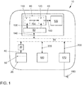
- Fig. 1 shows an inventive device designed as a motor vehicle 10.
- the motor vehicle 10 comprises an energy store designed as a tank 20, a sensor unit designed as a tank level sensor 30 and a combination instrument 40.
- the tank 20 contains an amount of fuel that represents an energy reserve for the operation of the motor vehicle.
- the amount of fuel is represented by a tank level 50, which forms a measure of how much fuel is still in the tank 20.
- the tank level 50 is determined by the tank level sensor 30 and is indicated by an arrow 60 which, by means of its arrow, indicates the direction of the information or data flow.
- the determined Tank level 50 is provided as the first measured value on a CAN bus 70 (CAN, Controller Area Network).
- the instrument cluster 40 has a data interface 80, a central control unit 90 and a display area 100.
- the central control unit 90 contains a computing unit 110 and a control unit 120 as integral components.
- the computing unit 110 receives data from the CAN bus 70 via the data interface 80 and provides data via the data interface 80 for the CAN bus; this bidirectional data transmission is indicated by double arrows 130 and 140.
- the computing unit 110 also sends data to the control unit 120 and is illustrated by an arrow 150.
- This data sent to the control unit 120 contains information that is to be reproduced on the display surface 100.
- the control unit 120 generates control signals with which the display area 100 is controlled in such a way that a desired reproduction is made to a user; the control of the display area 100 with the control signals can be recognized by an arrow 160.
- the generation of the control signals can also include the processing of the data received by the computing unit 110, in particular graphic processing, in order to bring about a specific graphic representation on the display surface 100.
- the control unit 120 is also set up to receive data via the data interface 80 from the CAN bus; this unidirectional data transmission can be recognized by an arrow 150.
- the motor vehicle 10 also has an infotainment system 170 and a navigation system 180.
- the infotainment system 170 is connected to an antenna 190, via which it can receive traffic information, for example.
- the traffic information is provided by the infotainment system 170 via the CAN bus 70 to other systems, for example the navigation system 180 and the instrument cluster 40; this data transmission is indicated by an arrow 200.
- the navigation system 180 exchanges data with other systems via the CAN bus 70 and is illustrated by a double arrow 205.
- Fig. 2 shows a flowchart of a method according to the invention, which in the device Fig. 1 is carried out.
- the computing unit 110 receives the tank level 50 as the first measured value, which was measured by the tank level sensor 30 and provided on the CAN bus 70.
- the computing unit 110 transmits the tank level 50 to the control unit 110 in order to display the current tank level 50 to the user on the display surface 100 in a step 220.
- the computing unit 110 compares the tank level 50 with a threshold value, which is predefined and stored in a memory (not shown) from which the computing unit 110 reads the threshold value.
- the computing unit 110 determines that the tank level 50 is greater than the threshold value, then the computing unit 110 waits until a new tank level is provided; this is indicated by an arrow 240 which goes back from step 230 to step 210.
- the computing unit 110 determines that the tank level 50 has reached or fallen below the threshold value, then a predefined condition has occurred.
- the arithmetic unit 110 then calculates, in a step 250, the expected remaining range of the motor vehicle 10 which is related to the fuel level 50 and which the motor vehicle 10 can still cover at the fuel level 50.
- the computing unit 110 uses information that allows a forecast that is as accurate as possible. This information includes, in particular, the tank level 50 and an average consumption of the motor vehicle 10, which in the present case is determined from consumption measurements during a predefined period of time before the condition occurs.
- information from the navigation system 180 (such as topographical data from route sections in the vicinity of the motor vehicle 10 or along a specific route) and the traffic information from the infotainment system 170 are taken into account when determining the remaining range, if such information is available.
- the determined remaining range is transmitted to the control unit 120.
- control unit 120 In a step 260, the control unit 120 generates graphic data from the remaining range received by the computing unit 110 for a graphic representation of the remaining range on the freely programmable display area 100.
- the display area 100 is controlled with this graphic data and shows the user the remaining range in a desired manner.
- FIG. 3 shows a section of the display area 100.
- a tank level indicator 270 is shown, which is identified by a graphic tank symbol 280.
- the current tank level 50 is shown on a scale 300 with the aid of a reading mark designed as a pointer 290.
- the pointer 290 partially covers a graduation line 310 of the scale, which indicates that the tank 20 is three-quarters full of fuel. It can be seen that the scale can be seen completely from the display empty "0" to half full “1/2" to full “1/1". From the description of the method according to the invention in Fig. 2 it follows that the condition has not yet occurred.
- the pointer 290 divides the scale 300 into an area 310 "above” the reading mark and an area 320 "below” the reading mark.
- Fig. 4 shows the section of the display area 100 Fig. 3 at a time when the condition has occurred.
- the scale 300 can no longer be seen completely, but only from the display empty "0" to the display half full “1 /".
- the second measured value "still 34 km” representing the remaining range 330 of the motor vehicle 10 is reproduced in such a way that it partially covers the scale 300 in the area 310 "above”.
- the scale 300 also has a visually highlighted reserve area 340 which extends over the lower eighth to a first division 350 of the scale 300. It is assumed that the condition is: Has the current tank level 50 reached or fallen below the reserve area 340?
Landscapes
- Engineering & Computer Science (AREA)
- Chemical & Material Sciences (AREA)
- Combustion & Propulsion (AREA)
- Transportation (AREA)
- Mechanical Engineering (AREA)
- Instrument Panels (AREA)
- Navigation (AREA)
- Testing, Inspecting, Measuring Of Stereoscopic Televisions And Televisions (AREA)
Description
- Die Erfindung betrifft ein Verfahren zur Wiedergabe von Messwerten, bei dem ein einen Energievorrat eines Energiespeichers repräsentierender erster Messwert empfangen wird, ein mit dem ersten Messwert in Beziehung stehender zweiter Messwert ermittelt wird, der erste Messwert mit Hilfe einer Ablesemarke an einer Skala wiedergegeben wird und der zweite Messwert wiedergegeben wird.
- Die Erfindung betrifft ferner eine Vorrichtung zur Wiedergabe von Messwerten mit einer Anzeigefläche, einer Datenschnittstelle, einer Recheneinheit, die eingerichtet ist, den ersten Messwert über die Datenschnittstelle zu empfangen und den zweiten Messwert zu ermitteln, und einer Steuereinheit, die eingerichtet ist, den ersten Messwert mit Hilfe der Ablesemarke an der Skala und den zweiten Messwert auf der Anzeigefläche wiederzugeben.
- Ein derartiges Verfahren lässt sich der
DE 199 59 597 C1 entnehmen. Bei der hier offenbarten Ausführungsform wird ein elektronisch ansteuerbares Display in einem Kraftfahrzeug derart angesteuert, dass mindestens zwei miteinander in einem Wirkzusammenhang stehende Informationen durch grafische Darstellung im Vergleich angezeigt werden. Als in einem Wirkzusammenhang stehende Informationen sind beispielhaft folgende Wertepaare genannt: Reichweite/Distanz, Tankinhalt/Reichweite. Dabei werden die Informationen am selben Ort im Wechsel nacheinander angezeigt. - Das Dokument
EP 2 489 990 A1 offenbart den Oberbegriff des Anspruchs 1. - Der Erfindung liegt die Aufgabe zugrunde, den Informationsgehalt bei dem eingangs beschriebenen Verfahren und der eingangs beschriebenen Vorrichtung für einen Benutzer zu verbessern.
- Diese Aufgabe wird erfindungsgemäß mit einem Verfahren der eingangs erwähnten Art dadurch gelöst, dass wenn der erste Messwert einen Schwellenwert erreicht oder unterschreitet, der zweite Messwert die Skala in einem Bereich oberhalb der Ablesemarke zumindest teilweise überdeckend wiedergegeben wird.
- Der Kern der Erfindung liegt darin, dass dem Benutzer sowohl der erste Messwert als auch der zweite Messwert gleichzeitig angezeigt werden. Der zweite Messwert wird oberhalb der Ablesemarke wiedergegeben. "Oberhalb" im Sinne dieser Erfindung ist auf den mittels der Ablesemarke an der Skala wiedergebbaren Wertebereich bezogen und meint den Bereich der Skala, der zwischen dem durch die Ablesemarke repräsentierten Wert und dem einen vollständig gefüllten Energiespeicher repräsentierenden Wert liegt. Die Ablesemarke selbst ist nicht Teil des Bereiches "oberhalb". Diese besondere Art und Weise der Wiedergabe des ersten Messwertes und des zweiten Messwertes stellt für den Benutzer einen Gewinn an Information dar, ohne dass eine für ihn wichtige Information entfällt.
- Der Begriff "Messwert" ist weit zu verstehen. Er umfasst zunächst einen direkt gemessenen Wert einer Messgröße. Darüber hinaus umfasst er auch einen indirekt gemessenen Wert einer Messgröße, bei dem der Wert aus einer direkten Messung oder mehreren direkten Messungen abgeleitet wird.
- Unter einer Bedingung im Sinne dieser Erfindung ist insbesondere zu verstehen, dass der erste Messwert einen Schwellenwert erreicht oder unterschreitet. Der Schwellenwert kann fest vorgegeben oder veränderlich sein. Ist der Schwellenwert veränderlich, so kann er beispielsweise in Abhängigkeit von der zeitlichen Änderung und/oder zeitlichen Änderungsrate des Energievorrates verändert werden.
- Der zweite Messwert braucht nicht schon dann oder immer dann ermittelt zu werden, wenn der erste Messwert erhalten worden ist. Wird der Eintritt der Bedingung nicht anhand des zweiten Messwertes geprüft, genügt es, den zweiten Messwert mit oder unmittelbar nach Eintritt der Bedingung zu ermitteln.
- Die "überdeckende" Wiedergabe des zweiten Messwertes braucht nicht intransparent zu erfolgen, also in dem Sinne, dass die Skala in diesem überdeckten Bereich nicht mehr sichtbar ist. Von der Erfindung wird auch ein transparentes Überdecken der Skala erfasst, das heißt, die Skala darf hinter dem zweiten Messwert durchscheinen. Die transparente Ausführung kommt insbesondere dann in Betracht, wenn der erste Messwert und der zweite Messwert auf räumlich getrennten Anzeigeflächen wiedergegeben und mit Hilfe eines teildurchlässigen Spiegels in Blickrichtung des Benutzers übereinandergelegt werden.
- In einer Ausführungsform ist der Energiespeicher als Akkumulator ausgebildet. Zweckmäßigerweise repräsentiert der erste Messwert in dieser Ausführungsform den Ladezustand des Akkumulators. Der Akkumulator kann für sehr unterschiedliche Anwendungen und Einsatzzwecke ausgebildet sein: Antriebsbatterie eines Elektrofahrzeugs; Akkumulator für einen tragbaren Computer (Laptop); Akkumulator für ein mobiles Kommunikationsgerät, beispielsweise eines sogenannten Smartphones.
- In einer weiteren Ausführungsform ist der Energiespeicher als Kraftstoffbehälter eines Fahrzeugs (Land-, Wasser- oder Luftfahrzeug) ausgebildet. Zweckmäßigerweise repräsentiert der erste Messwert in dieser Ausführungsform den Füllstand des Kraftstoffbehälters. Als Kraftstoffe kommen beispielsweise in Betracht: Ottokraftstoffe, Dieselkraftstoffe, Autogas (LPG, Liquified Petroleum Gas), verdichtetes Erdgas (CNG, Compressed Natural Gas), Flüssigerdgas (LNG, Liquefied Natural Gas), Wasserstoff für Brennstoffzellen.
- Vorteilhafterweise werden die Skala und die Ablesemarke als Grafiken erzeugt. Unter einer "Grafik" im Sinne dieser Erfindung sind sowohl eine Grafikdatei mit digitalen Daten zur Wiedergabe eines Bildes auf einem Bildschirm sowie das auf diese Weise erzeugte Bild zu verstehen. Solche Grafiken werden vorteilhafterweise auf einem freiprogrammierbaren Bildschirm wiedergeben. Auf diese Weise lassen sich die Grafiken einfach in ihrer Gestaltung an unterschiedliche Benutzerkreise anpassen. Darüber hinaus lassen sich die Grafiken einfach an unterschiedliche Rahmenbedingungen anpassen, beispielsweise an verschieden große Anzeigeflächen oder an weitere darzustellende Informationen. Die Ablesemarke kann unterschiedlich ausgebildet sein, etwa als Zeiger oder Balken. Zweckmäßigerweise wird auch der zweite Messwert als Grafik erzeugt.
- In einer besonderen Ausführungsform repräsentiert der zweite Messwert eine Restbetriebsdauer. Die Restbetriebsdauer repräsentiert je nach Anwendungsfall unterschiedliche Größen: Restbetriebszeit eines Laptops oder Smartphones; Restreichweite eines Land-, Wasser- oder Luftfahrzeugs. Als Landfahrzeug kommt insbesondere ein Kraftfahrzeug in Betracht.
- Die genannte Aufgabe wird erfindungsgemäß ferner mit einer Vorrichtung der eingangs erwähnten Art dadurch gelöst, dass die Steuereinheit eingerichtet ist, den zweiten Messwert bei Eintritt der Bedingung die Skala in dem Bereich oberhalb der Ablesemarke zumindest teilweise überdeckend wiederzugeben.
- Die Datenschnittstelle der erfindungsgemäßen Vorrichtung dient der Übertragung von Daten, insbesondere digitaler Daten, und kann unterschiedlich ausgebildet sein: unidirektional oder bidirektional; drahtgebunden oder drahtungebunden. Über die Datenschnittstelle empfängt die Recheneinheit insbesondere den ersten Messwert.
- Denkbar ist auch, dass die Recheneinheit weitere Daten über die Datenschnittstelle empfängt. Zweckmäßig sind in diesem Zusammenhang Daten, die für die Ermittlung des zweiten Messwertes nützlich sind. Ist die Vorrichtung beispielsweise als sogenanntes Kombiinstrument für ein Kraftfahrzeug ausgebildet, kommen folgende Daten in Betracht: Navigationsdaten; Wetterdaten; Verkehrsinformationen; Sitzbelegungsdaten; Fahrzeugdaten, wie zum Beispiel Gewicht, Anbauten, Anhänger, Reifendaten. Diese Daten haben Einfluss auf die Restreichweite. Aus Navigationsdaten lassen sich Rückschlüsse auf einen voraussichtlichen Energiebedarf ziehen, der auf Eigenschaften der zu befahrenen Straßenabschnitte zurückzuführen ist, wie Straßenbelag, topografische Eigenschaften, Geschwindigkeitsbegrenzungen, Anzahl von Ampeln. Wetterdaten geben verbrauchsrelevante Informationen, wie Sonne, Regen, Schnee, Nebel, Glatteis. Aus Verkehrsinformationen lassen sich verbrauchsrelevante Informationen gewinnen, wie Verkehrsbehinderungen, Stau, stockender Verkehr, Baustellen, Verkehrsflussdaten. Die Sitzbelegung beeinflusst das Gewicht des Kraftfahrzeugs und damit auch den Energiebedarf, zum Beispiel den Kraftstoffverbrauch. Sitzbelegungsdaten werden beispielsweise von Sitzbelegungssensoren bereitgestellt.
- Die Begriffe "Recheneinheit" und "Steuereinheit" sind funktional zu verstehen. Die Recheneinheit ist insbesondere funktional für die Berechnung des mit dem ersten Messwert in Beziehung stehenden zweiten Messwertes zuständig. Die Steuereinheit ist insbesondere funktional für das Ansteuern der Anzeigefläche zuständig. Hierzu erzeugt die Steuereinheit aus dem ersten und zweiten Messwert Grafik- und/oder Steuerdaten für die Anzeigefläche, die eine gewünschte Wiedergabe dieser Messwerte auf der Anzeigefläche realisieren. Die Recheneinheit und die Steuereinheit können separat oder als integrale Bestandteile einer Zentralsteuereinheit ausgebildet sein.
- In einer bevorzugten Ausführungsform ist die Vorrichtung als Fahrzeug (Land-, Wasser- oder Luftfahrzeug) ausgebildet, insbesondere als Kraftfahrzeug. In einer weiteren Ausführungsform ist die Vorrichtung als mobiles Kommunikationsgerät ausgebildet.
- In der Zeichnung ist eine als Beispiel dienende Ausführungsform der Erfindung dargestellt. Es zeigen:
- Fig. 1
- ein Blockschaltbild einer erfindungsgemäßen Vorrichtung;
- Fig. 2
- ein Flussdiagramm eines erfindungsgemäßen Verfahrens, das auf der Vorrichtung aus
Figur 1 durchgeführt wird; - Fig. 3
- ein Anzeigebild einer Anzeigefläche der Vorrichtung aus
Figur 1 vor Eintritt einer Bedingung und - Fig. 4
- ein Anzeigebild der Anzeigefläche der Vorrichtung aus
Figur 1 nach Eintritt der Bedingung. -
Fig. 1 zeigt eine als Kraftfahrzeug 10 ausgebildete erfindungsgemäße Vorrichtung. Das Kraftfahrzeug 10 umfasst einen als Tank 20 ausgebildeten Energiespeicher, eine als Tankstandsensor 30 ausgebildete Sensoreinheit und ein Kombiinstrument 40. - Der Tank 20 beinhaltet eine Kraftstoffmenge, die einen Energievorrat für den Betrieb des Kraftfahrzeugs darstellt. Die Kraftstoffmenge wird von einem Tankstand 50 repräsentiert, der ein Maß dafür bildet, wie viel Kraftstoff sich noch in dem Tank 20 befindet. Der Tankstand 50 wird durch den Tankstandsensor 30 ermittelt und ist durch einen Pfeil 60 angedeutet, der durch seinen Pfeil die Richtung des Informations- oder Datenflusses anzeigt. Der ermittelte Tankstand 50 wird als erster Messwert auf einem CAN-Bus 70 (CAN, Controller Area Network) bereitgestellt.
- Das Kombiinstrument 40 weist eine Datenschnittstelle 80, eine Zentralsteuereinheit 90 und eine Anzeigefläche 100 auf. Die Zentralsteuereinheit 90 beinhaltet als integrale Bestandteile eine Recheneinheit 110 und eine Steuereinheit 120.
- Die Recheneinheit 110 empfängt über die Datenschnittstelle 80 Daten von dem CAN-Bus 70 und stellt Daten über die Datenschnittstelle 80 für den CAN-Bus bereit; diese bidirektionale Datenübertragung ist durch Doppelpfeile 130 und 140 angedeutet. Die Recheneinheit 110 sendet auch Daten an die Steuereinheit 120 und wird durch einen Pfeil 150 veranschaulicht. Diese an die Steuereinheit 120 gesendeten Daten enthalten Informationen, die auf der Anzeigefläche 100 wiedergegeben werden sollen. Hierzu erzeugt die Steuereinheit 120 Steuersignale, mit denen die Anzeigefläche 100 so angesteuert wird, dass eine gewünschte Wiedergabe an einen Benutzer erfolgt; das Ansteuern der Anzeigefläche 100 mit den Steuersignalen ist an einem Pfeil 160 zu erkennen. Das Erzeugen der Steuersignale kann auch die Bearbeitung der von der Recheneinheit 110 empfangenen Daten umfassen, insbesondere eine grafische Aufbereitung, um eine bestimmte grafische Darstellung auf der Anzeigefläche 100 zu bewirken. Die Steuereinheit 120 ist auch eingerichtet, Daten über die Datenschnittstelle 80 von dem CAN-Bus zu empfangen; diese unidirektionale Datenübertragung ist an einem Pfeil 150 zu erkennen.
- Das Kraftfahrzeug 10 weist ferner ein Infotainmentsystem 170 und ein Navigationssystem 180 auf. Das Infotainmentsystem 170 ist an eine Antenne 190 angeschlossen, über die es beispielsweise Verkehrsinformationen empfangen kann. Die Verkehrsinformationen werden von dem Infotainmentsystem 170 über den CAN-Bus 70 anderen Systemen bereitgestellt, beispielsweise dem Navigationssystem 180 und dem Kombiinstrument 40; diese Datenübertragung ist durch einen Pfeil 200 angedeutet. Das Navigationssystem 180 tauscht über den CAN-Bus 70 Daten mit anderen Systemen aus und wird durch einen Doppelpfeil 205 veranschaulicht.
-
Fig. 2 zeigt ein Flussdiagramm eines erfindungsgemäßen Verfahrens, das in der Vorrichtung ausFig. 1 durchgeführt wird. - In einem Schritt 210 empfängt die Recheneinheit 110 den Tankstand 50 als den ersten Messwert, der von dem Tankstandsensor 30 gemessen und auf dem CAN-Bus 70 bereitgestellt worden ist. Die Recheneinheit 110 überträgt den Tankstand 50 an die Steuereinheit 110, um dem Benutzer in einem Schritt 220 den aktuellen Tankstand 50 auf der Anzeigefläche 100 anzuzeigen.
- In einem Schritt 230 vergleicht die Recheneinheit 110 den Tankstand 50 mit einem Schwellenwert, der vordefiniert und in einem Speicher (nicht dargestellt) gespeichert ist, aus dem die Recheneinheit 110 den Schwellenwert liest.
- Stellt die Recheneinheit 110 fest, dass der Tankstand 50 größer ist als der Schwellenwert, dann wartet die Recheneinheit 110 ab, bis ein neuer Tankstand bereitgestellt wird; dies ist durch einen Pfeil 240 angedeutet, der von dem Schritt 230 zurück auf den Schritt 210 geht.
- Stellt die Recheneinheit 110 dagegen fest, dass der Tankstand 50 den Schwellenwert erreicht oder unterschritten hat, dann ist eine vordefinierte Bedingung eingetreten. Die Recheneinheit 110 berechnet sodann in einem Schritt 250 die mit dem Tankstand 50 in Beziehung stehende voraussichtliche Restreichweite des Kraftfahrzeugs 10, die das Kraftfahrzeug 10 bei dem Tankstand 50 noch zurücklegen kann. Für diese Berechnung greift die Recheneinheit 110 auf Informationen zurück, die eine möglichst genaue Prognose erlauben. Zu diesen Informationen zählen insbesondere der Tankstand 50 und ein Durchschnittsverbrauch des Kraftfahrzeugs 10, der vorliegend aus Verbrauchsmessungen während einer vordefinierten Zeitspanne vor Eintritt der Bedingung ermittelt wird. Zudem werden Informationen des Navigationssystems 180 (wie topografische Daten von Streckenabschnitten in der Umgebung des Kraftfahrzeugs 10 oder entlang einer bestimmten Route) und die Verkehrsinformationen des Infotainmentsystems 170 bei der Ermittlung der Restreichweite berücksichtigt, sofern solche Informationen vorhanden sind. Die ermittelte Restreichweite wird an die Steuereinheit 120 übertragen.
- Die Steuereinheit 120 erzeugt in einem Schritt 260 aus der von der Recheneinheit 110 empfangenen Restreichweite Grafikdaten für eine grafische Wiedergabe der Restreichweite auf der freiprogrammierbaren Anzeigefläche 100. Mit diesen Grafikdaten wird die Anzeigefläche 100 angesteuert und zeigt dem Benutzer die Restreichweite in einer gewünschten Weise an.
-
Fig.3 zeigt einen Ausschnitt der Anzeigefläche 100. In diesem Ausschnitt ist eine Tankstandanzeige 270 dargestellt, die durch ein grafisches Tanksymbol 280 gekennzeichnet ist. Der aktuelle Tankstand 50 wird mit Hilfe einer als Zeiger 290 ausgeführten Ablesemarke an einer Skala 300 wiedergegeben. Der Zeiger 290 überdeckt teilweise einen Teilstrich 310 der Skala, der anzeigt, dass der Tank 20 zu dreiviertel mit Kraftstoff gefüllt ist. Es ist zu erkennen, dass die Skala vollständig von der Anzeige leer "0" über halbvoll "1/2" bis voll "1/1" zu sehen ist. Aus der Beschreibung des erfindungsgemäßen Verfahrens inFig. 2 folgt daraus, dass die Bedingung noch nicht eingetreten ist. Der Zeiger 290 teilt die Skala 300 in einen Bereich 310 "oberhalb" der Ablesemarke und einen Bereich 320 "unterhalb" der Ablesemarke. -
Fig. 4 zeigt den Ausschnitt der Anzeigefläche 100 ausFig. 3 zu einem Zeitpunkt, in dem die Bedingung eingetreten ist. Die Skala 300 ist nicht mehr vollständig zu sehen, sondern nur noch von der Anzeige leer "0" bis zur Anzeige etwa halbvoll "1/". In dem Bereich 310 "oberhalb" ist der die Restreichweite 330 des Kraftfahrzeugs 10 repräsentierende zweite Messwert "noch 34 km" derart wiedergegeben, dass er die Skala 300 in dem Bereich 310 "oberhalb" teilweise überdeckt. Die Skala 300 weist noch einen visuell hervorgehobenen Reservebereich 340 auf, der sich über das untere Achtel bis zu einem ersten Teilstrich 350 der Skala 300 erstreckt. Es sei angenommen, dass die Bedingung lautet: Hat der aktuelle Tankstand 50 den Reservebereich 340 erreicht oder unterschritten? Wenn diese Bedingung eintritt - also aktueller Tankstand 50 kleiner oder gleich ein Achtel - wird der zweite Messwert "noch ..." eingeblendet, wobei die "..." die Restreichweite angeben, die bei Eintritt der Bedingung vorlag. InFig. 4 liegt der Eintritt der Bedingung zeitlich zurück, da der Zeiger 290 schon auf eine Stelle der Skala 300 zeigt, die unterhalb des ersten Teilstrichs liegt.Bezugszeichenliste 10 Kraftfahrzeug 190 Antenne 20 Tank 200 Pfeil 30 Tankstandsensor 205 Doppelpfeil 40 Kombiinstrument 210 Schritt 50 Tankstand 220 Schritt 60 Pfeil 230 Schritt 70 CAN-Bus 240 Pfeil 80 Schnittstelle 250 Schritt 90 Zentralsteuereinheit 260 Schritt 100 Anzeigefläche 270 Tankstandanzeige 110 Recheneinheit 280 Tanksymbol 120 Steuereinheit 290 Zeiger 130 Doppelpfeil 300 Skala 140 Doppelpfeil 310 Bereich "oberhalb" 150 Pfeil 320 Bereich "unterhalb" 160 Pfeil 330 Restreichweite 170 Infotainmentsystem 340 Reservebereich 180 Navigationssystem 350 Teilstrich
Claims (9)
- Verfahren zur Wiedergabe von Messwerten, bei dem ein einen Energievorrat eines Energiespeichers repräsentierender erster Messwert empfangen wird, ein mit dem ersten Messwert in Beziehung stehender zweiter Messwert ermittelt wird, der erste Messwert mit Hilfe einer Ablesemarke an einer Skala (300) wiedergegeben wird und der zweite Messwert wiedergegeben wird, dadurch gekennzeichnet, dass, wenn der erste Messwert einen Schwellenwert erreicht oder unterschreitet, der zweite Messwert die Skala (300) in einem Bereich (310) oberhalb der Ablesemarke zumindest teilweise überdeckend (330) wiedergegeben wird.
- Verfahren nach Anspruch 1, dadurch gekennzeichnet, dass der Energiespeicher als Akkumulator ausgebildet ist und der erste Messwert den Ladezustand des Akkumulators repräsentiert.
- Verfahren nach Anspruch 1, dadurch gekennzeichnet, dass der Energiespeicher als Kraftstoffbehälter eines Fahrzeugs ausgebildet ist und der erste Messwert den Füllstand des Kraftstoffbehälters repräsentiert.
- Verfahren nach einem der vorstehenden Ansprüche, dadurch gekennzeichnet, dass die Skala (300), die Ablesemarke und der zweite Messwert als Bildschirmgrafiken realisiert werden.
- Verfahren nach einem der vorstehenden Ansprüche, dadurch gekennzeichnet, dass der zweite Messwert eine Restbetriebsdauer repräsentiert.
- Vorrichtung zum Durchführen des Verfahrens nach einem der Ansprüche 1 bis 5 mit einer Anzeigefläche (100), einer Datenschnittstelle (80), einer Recheneinheit (110), die eingerichtet ist, den ersten Messwert über die Datenschnittstelle (80) zu empfangen und den zweiten Messwert zu ermitteln, und einer Steuereinheit (120), die eingerichtet ist, den ersten Messwert mit Hilfe der Ablesemarke an der Skala (300) und den zweiten Messwert auf der Anzeigefläche (100) wiederzugeben, dadurch gekennzeichnet, dass die Steuereinheit (120) eingerichtet ist, wenn der erste Messwert einen Schwellenwert erreicht oder unterschreitet, den zweiten Messwert die Skala (300) in dem Bereich (310) oberhalb der Ablesemarke zumindest teilweise überdeckend (330) wiederzugeben.
- Vorrichtung nach Anspruch 6, gekennzeichnet durch den Energiespeicher und eine Sensoreinheit zum Ermitteln des ersten Messwertes.
- Vorrichtung nach Anspruch 7, dadurch gekennzeichnet, dass die Vorrichtung als Fahrzeug ausgebildet ist.
- Vorrichtung nach Anspruch 7, dadurch gekennzeichnet, dass die Vorrichtung als mobiles Kommunikationsgerät ausgebildet ist.
Applications Claiming Priority (2)
| Application Number | Priority Date | Filing Date | Title |
|---|---|---|---|
| DE102012021735.8A DE102012021735A1 (de) | 2012-11-05 | 2012-11-05 | Verfahren und Vorrichtung zur Wiedergabe von den Energievorrat eines Energiespeichers repräsentierenden Messwerten |
| PCT/EP2013/071931 WO2014067801A2 (de) | 2012-11-05 | 2013-10-21 | Verfahren und vorrichtung zur wiedergabe von den energievorrat eines energiespeichers repräsentierenden messwerten |
Publications (2)
| Publication Number | Publication Date |
|---|---|
| EP2914453A2 EP2914453A2 (de) | 2015-09-09 |
| EP2914453B1 true EP2914453B1 (de) | 2020-01-01 |
Family
ID=49474402
Family Applications (1)
| Application Number | Title | Priority Date | Filing Date |
|---|---|---|---|
| EP13780120.5A Active EP2914453B1 (de) | 2012-11-05 | 2013-10-21 | Verfahren und vorrichtung zur wiedergabe von den energievorrat eines energiespeichers repräsentierenden messwerten |
Country Status (4)
| Country | Link |
|---|---|
| EP (1) | EP2914453B1 (de) |
| DE (1) | DE102012021735A1 (de) |
| ES (1) | ES2767577T3 (de) |
| WO (1) | WO2014067801A2 (de) |
Families Citing this family (3)
| Publication number | Priority date | Publication date | Assignee | Title |
|---|---|---|---|---|
| DE102014212093A1 (de) * | 2014-06-24 | 2015-12-24 | Volkswagen Aktiengesellschaft | Verfahren und Vorrichtung zum Anzeigen eines kritischen Wertebereichs eines ersten fahrzeugspezifischen Parameters in einem Fahrzeug |
| DE102014220128A1 (de) * | 2014-10-06 | 2016-04-07 | Bayerische Motoren Werke Aktiengesellschaft | Verfahren und Vorrichtung zur Anzeige eines Energieinhalts eines Energiespeichers eines Kraftfahrzeugs und Kraftfahrzeug |
| DE102014220129A1 (de) * | 2014-10-06 | 2016-04-07 | Bayerische Motoren Werke Aktiengesellschaft | Verfahren und Vorrichtung zur Anzeige eines Energieinhalts eines Energiespeichers eines Kraftfahrzeugs und Kraftfahrzeug |
Family Cites Families (16)
| Publication number | Priority date | Publication date | Assignee | Title |
|---|---|---|---|---|
| DE673563C (de) * | 1935-05-30 | 1939-03-24 | Vdo Tachometer A G | Anordnung von Sammelanzeigegeraeten |
| DE3315386A1 (de) * | 1983-04-28 | 1984-10-31 | Messerschmitt-Bölkow-Blohm GmbH, 8012 Ottobrunn | Anzeigegeraet zur bildlichen darstellung von messwerten |
| DE4125372C1 (en) * | 1991-07-31 | 1992-08-13 | Messerschmitt-Boelkow-Blohm Gmbh, 8012 Ottobrunn, De | Monitoring aircraft power unit esp. helicopter gas turbine drives - indicating only critical instantaneous parameters on display and warning of values outside set ranges |
| DE19507997B4 (de) * | 1995-03-07 | 2007-07-12 | Robert Bosch Gmbh | Verfahren zur Anzeige von mehreren Informationen |
| IT1289710B1 (it) * | 1996-12-04 | 1998-10-16 | Fiat Ricerche | Dispositivo di visualizzazione di informazioni di un autoveicolo |
| DE29704844U1 (de) * | 1997-03-07 | 1997-07-03 | Tegethoff Marius | Analoge Kraftstoffverbrauchsanzeige mit Zusatzanzeige |
| DE19733650A1 (de) * | 1997-08-04 | 1999-02-11 | Valeo Borg Instr Verw Gmbh | Anzeigeinstrument |
| DE29715340U1 (de) * | 1997-08-27 | 1998-02-12 | Pasligh, Josef, 26871 Papenburg | Doppeldrehzahlmesser |
| JP2000205925A (ja) * | 1999-01-07 | 2000-07-28 | Nissan Motor Co Ltd | 車両用燃費表示装置 |
| DE19959597C1 (de) | 1999-12-10 | 2001-02-15 | Bayerische Motoren Werke Ag | Verfahren und Vorrichtung zur optischen Anzeige von Informationen in Kraftfahrzeugen |
| DE20015856U1 (de) * | 2000-09-13 | 2000-11-23 | CAA AG, 70794 Filderstadt | Anzeigevorrichtung |
| FR2898551B1 (fr) * | 2006-03-15 | 2009-02-06 | Renault Sas | Vehicule automobile comportant des moyens d'affichage de l'autonomie et de la quantite de carburant dans le reservoir |
| DE102008021241B4 (de) * | 2008-04-28 | 2018-04-19 | Bombardier Transportation Gmbh | Messwert-Anzeige, insbesondere im Führerstand eines Schienenfahrzeugs |
| DE102008032062B4 (de) * | 2008-07-08 | 2018-06-28 | Volkswagen Ag | Verfahren und Vorrichtung zum Anzeigen der Größe der Energiereserven zum Antrieb eines Kraftfahrzeugs |
| EP2489990A1 (de) * | 2011-02-15 | 2012-08-22 | Brusa Elektronik AG | Anzeigevorrichtung für ein Elektrofahrzeug |
| DE102011116314A1 (de) * | 2011-10-18 | 2013-04-18 | Daimler Ag | Hybrid-Kraftfahrzeug mit Anzeige-Instrument und Verfahren zur Anzeige von Informationen über Betriebsparameter in einem Hybrid-Kraftfahrzeug |
-
2012
- 2012-11-05 DE DE102012021735.8A patent/DE102012021735A1/de not_active Withdrawn
-
2013
- 2013-10-21 WO PCT/EP2013/071931 patent/WO2014067801A2/de not_active Ceased
- 2013-10-21 EP EP13780120.5A patent/EP2914453B1/de active Active
- 2013-10-21 ES ES13780120T patent/ES2767577T3/es active Active
Non-Patent Citations (1)
| Title |
|---|
| None * |
Also Published As
| Publication number | Publication date |
|---|---|
| DE102012021735A1 (de) | 2014-05-08 |
| WO2014067801A2 (de) | 2014-05-08 |
| WO2014067801A3 (de) | 2014-07-10 |
| EP2914453A2 (de) | 2015-09-09 |
| ES2767577T3 (es) | 2020-06-18 |
Similar Documents
| Publication | Publication Date | Title |
|---|---|---|
| WO2013013730A1 (de) | Verfahren zum bestimmen einer fahrtreichweite eines kraftwagens | |
| DE102005016006A1 (de) | Informationssystem und Verfahren zum Liefern von Tankstelleninformationen für ein Kraftfahrzeug | |
| DE102012019056A1 (de) | Verfahren zur Ermittlung einer Restreichweite eines Kraftfahrzeuges | |
| DE102014208757A1 (de) | Verfahren zur Prädiktion eines Treibstoffverbrauchs und der Ankunftszeit für eine Fahrzeugnavigationsvorrichtung | |
| DE102013002243A1 (de) | Verfahren und Vorrichtung zur Reichweitenbestimmung für ein Fahrzeug | |
| DE102016209494A1 (de) | Anzeige der gesamtreichweite der fahrzeugfahrt, die leicht verständlich ist und reichweitenängste minimiert | |
| DE102010038539A1 (de) | Verbrauchsanzeigesystem für ein Fahrzeug, Verfahren | |
| DE102009028767A1 (de) | Fahrerassistenzsystem für Kraftfahrzeuge | |
| WO2015132084A1 (de) | Verfahren und vorrichtung zur prognose einer reichweitenveränderung durch ein- oder ausschalten einer fahrzeugfunktion eines fahrzeugs | |
| EP2902243B1 (de) | Verfahren und Vorrichtung zum Anzeigen von Fahrzeugparametern | |
| EP2886385A1 (de) | Anzeigeeinrichtung für ein Fahrzeug | |
| DE102012221703A1 (de) | Routenführungssystem unter Ausnutzung mehrerer Energiequellen | |
| DE102013002240B3 (de) | Verfahren und Vorrichtung zur Reichweitenkennzeichnung für ein Fahrzeug | |
| WO2014067801A2 (de) | Verfahren und vorrichtung zur wiedergabe von den energievorrat eines energiespeichers repräsentierenden messwerten | |
| DE102021006024A1 (de) | Verfahren zur Darstellung eines Abhängigkeit zwischen einer Fortbewegungsgeschwindigkeit und eines Verbrauchs eines Fahrzeugs | |
| DE102013014886B4 (de) | Verfahren zur Anzeige eines Füllstandswertes in einem Kraftfahrzeug und Kraftfahrzeug | |
| DE102014013186B4 (de) | Verschlusseinheit für einen Kraftstofftank eines Kraftwagens und Kraftwagen mit einer Verschlusseinheit | |
| DE102013011858A1 (de) | Verfahren zum Anzeigen des Tankinhalts | |
| DE102010048258A1 (de) | Verfahren zum Ausgeben von Informationen zu Ladestationen für Fahrzeuge mit Elektroantrieb und Navigationssystem für ein solches Fahrzeug | |
| DE102010039569A1 (de) | Verfahren und Vorrichtung zum Ermitteln einer Energieaufwandsinformation für eine Fahrt eines Landfahrzeugs | |
| DE102009007436B4 (de) | Verfahren und Vorrichtung zur Darstellung mindestens eines Werteverlaufs für ein Fahrzeug und Fahrzeug | |
| DE102014200610B4 (de) | Ermittlung und Anzeige eines normierten Kraftstoffverbrauchs | |
| DE102017214823B4 (de) | Verfahren und Vorrichtung zum Erstellen und Bereitstellen einer Karte zum Betreiben eines automatisierten Fahrzeugs | |
| DE102010019761A1 (de) | Verfahren zur Berücksichtigung von Windeinflüssen | |
| DE102013011550A1 (de) | Verfahren zur Erfassung und Anzeige eines Durchschnitts-Kraftstoffverbrauchs eines Kraftfahrzeugs |
Legal Events
| Date | Code | Title | Description |
|---|---|---|---|
| PUAI | Public reference made under article 153(3) epc to a published international application that has entered the european phase |
Free format text: ORIGINAL CODE: 0009012 |
|
| 17P | Request for examination filed |
Effective date: 20150605 |
|
| AK | Designated contracting states |
Kind code of ref document: A2 Designated state(s): AL AT BE BG CH CY CZ DE DK EE ES FI FR GB GR HR HU IE IS IT LI LT LU LV MC MK MT NL NO PL PT RO RS SE SI SK SM TR |
|
| AX | Request for extension of the european patent |
Extension state: BA ME |
|
| DAX | Request for extension of the european patent (deleted) | ||
| GRAP | Despatch of communication of intention to grant a patent |
Free format text: ORIGINAL CODE: EPIDOSNIGR1 |
|
| STAA | Information on the status of an ep patent application or granted ep patent |
Free format text: STATUS: GRANT OF PATENT IS INTENDED |
|
| INTG | Intention to grant announced |
Effective date: 20191009 |
|
| GRAS | Grant fee paid |
Free format text: ORIGINAL CODE: EPIDOSNIGR3 |
|
| GRAA | (expected) grant |
Free format text: ORIGINAL CODE: 0009210 |
|
| STAA | Information on the status of an ep patent application or granted ep patent |
Free format text: STATUS: THE PATENT HAS BEEN GRANTED |
|
| AK | Designated contracting states |
Kind code of ref document: B1 Designated state(s): AL AT BE BG CH CY CZ DE DK EE ES FI FR GB GR HR HU IE IS IT LI LT LU LV MC MK MT NL NO PL PT RO RS SE SI SK SM TR |
|
| REG | Reference to a national code |
Ref country code: GB Ref legal event code: FG4D Free format text: NOT ENGLISH |
|
| REG | Reference to a national code |
Ref country code: AT Ref legal event code: REF Ref document number: 1219369 Country of ref document: AT Kind code of ref document: T Effective date: 20200115 Ref country code: CH Ref legal event code: EP |
|
| REG | Reference to a national code |
Ref country code: IE Ref legal event code: FG4D Free format text: LANGUAGE OF EP DOCUMENT: GERMAN |
|
| REG | Reference to a national code |
Ref country code: DE Ref legal event code: R096 Ref document number: 502013014150 Country of ref document: DE |
|
| REG | Reference to a national code |
Ref country code: NL Ref legal event code: MP Effective date: 20200101 |
|
| REG | Reference to a national code |
Ref country code: ES Ref legal event code: FG2A Ref document number: 2767577 Country of ref document: ES Kind code of ref document: T3 Effective date: 20200618 |
|
| REG | Reference to a national code |
Ref country code: LT Ref legal event code: MG4D |
|
| PG25 | Lapsed in a contracting state [announced via postgrant information from national office to epo] |
Ref country code: RS Free format text: LAPSE BECAUSE OF FAILURE TO SUBMIT A TRANSLATION OF THE DESCRIPTION OR TO PAY THE FEE WITHIN THE PRESCRIBED TIME-LIMIT Effective date: 20200101 Ref country code: NO Free format text: LAPSE BECAUSE OF FAILURE TO SUBMIT A TRANSLATION OF THE DESCRIPTION OR TO PAY THE FEE WITHIN THE PRESCRIBED TIME-LIMIT Effective date: 20200401 Ref country code: FI Free format text: LAPSE BECAUSE OF FAILURE TO SUBMIT A TRANSLATION OF THE DESCRIPTION OR TO PAY THE FEE WITHIN THE PRESCRIBED TIME-LIMIT Effective date: 20200101 Ref country code: PT Free format text: LAPSE BECAUSE OF FAILURE TO SUBMIT A TRANSLATION OF THE DESCRIPTION OR TO PAY THE FEE WITHIN THE PRESCRIBED TIME-LIMIT Effective date: 20200527 Ref country code: NL Free format text: LAPSE BECAUSE OF FAILURE TO SUBMIT A TRANSLATION OF THE DESCRIPTION OR TO PAY THE FEE WITHIN THE PRESCRIBED TIME-LIMIT Effective date: 20200101 Ref country code: LT Free format text: LAPSE BECAUSE OF FAILURE TO SUBMIT A TRANSLATION OF THE DESCRIPTION OR TO PAY THE FEE WITHIN THE PRESCRIBED TIME-LIMIT Effective date: 20200101 |
|
| PG25 | Lapsed in a contracting state [announced via postgrant information from national office to epo] |
Ref country code: LV Free format text: LAPSE BECAUSE OF FAILURE TO SUBMIT A TRANSLATION OF THE DESCRIPTION OR TO PAY THE FEE WITHIN THE PRESCRIBED TIME-LIMIT Effective date: 20200101 Ref country code: SE Free format text: LAPSE BECAUSE OF FAILURE TO SUBMIT A TRANSLATION OF THE DESCRIPTION OR TO PAY THE FEE WITHIN THE PRESCRIBED TIME-LIMIT Effective date: 20200101 Ref country code: IS Free format text: LAPSE BECAUSE OF FAILURE TO SUBMIT A TRANSLATION OF THE DESCRIPTION OR TO PAY THE FEE WITHIN THE PRESCRIBED TIME-LIMIT Effective date: 20200501 Ref country code: HR Free format text: LAPSE BECAUSE OF FAILURE TO SUBMIT A TRANSLATION OF THE DESCRIPTION OR TO PAY THE FEE WITHIN THE PRESCRIBED TIME-LIMIT Effective date: 20200101 Ref country code: BG Free format text: LAPSE BECAUSE OF FAILURE TO SUBMIT A TRANSLATION OF THE DESCRIPTION OR TO PAY THE FEE WITHIN THE PRESCRIBED TIME-LIMIT Effective date: 20200401 Ref country code: GR Free format text: LAPSE BECAUSE OF FAILURE TO SUBMIT A TRANSLATION OF THE DESCRIPTION OR TO PAY THE FEE WITHIN THE PRESCRIBED TIME-LIMIT Effective date: 20200402 |
|
| REG | Reference to a national code |
Ref country code: DE Ref legal event code: R097 Ref document number: 502013014150 Country of ref document: DE |
|
| PG25 | Lapsed in a contracting state [announced via postgrant information from national office to epo] |
Ref country code: SK Free format text: LAPSE BECAUSE OF FAILURE TO SUBMIT A TRANSLATION OF THE DESCRIPTION OR TO PAY THE FEE WITHIN THE PRESCRIBED TIME-LIMIT Effective date: 20200101 Ref country code: EE Free format text: LAPSE BECAUSE OF FAILURE TO SUBMIT A TRANSLATION OF THE DESCRIPTION OR TO PAY THE FEE WITHIN THE PRESCRIBED TIME-LIMIT Effective date: 20200101 Ref country code: DK Free format text: LAPSE BECAUSE OF FAILURE TO SUBMIT A TRANSLATION OF THE DESCRIPTION OR TO PAY THE FEE WITHIN THE PRESCRIBED TIME-LIMIT Effective date: 20200101 Ref country code: RO Free format text: LAPSE BECAUSE OF FAILURE TO SUBMIT A TRANSLATION OF THE DESCRIPTION OR TO PAY THE FEE WITHIN THE PRESCRIBED TIME-LIMIT Effective date: 20200101 Ref country code: SM Free format text: LAPSE BECAUSE OF FAILURE TO SUBMIT A TRANSLATION OF THE DESCRIPTION OR TO PAY THE FEE WITHIN THE PRESCRIBED TIME-LIMIT Effective date: 20200101 |
|
| PLBE | No opposition filed within time limit |
Free format text: ORIGINAL CODE: 0009261 |
|
| STAA | Information on the status of an ep patent application or granted ep patent |
Free format text: STATUS: NO OPPOSITION FILED WITHIN TIME LIMIT |
|
| 26N | No opposition filed |
Effective date: 20201002 |
|
| PG25 | Lapsed in a contracting state [announced via postgrant information from national office to epo] |
Ref country code: PL Free format text: LAPSE BECAUSE OF FAILURE TO SUBMIT A TRANSLATION OF THE DESCRIPTION OR TO PAY THE FEE WITHIN THE PRESCRIBED TIME-LIMIT Effective date: 20200101 Ref country code: SI Free format text: LAPSE BECAUSE OF FAILURE TO SUBMIT A TRANSLATION OF THE DESCRIPTION OR TO PAY THE FEE WITHIN THE PRESCRIBED TIME-LIMIT Effective date: 20200101 |
|
| REG | Reference to a national code |
Ref country code: CH Ref legal event code: PL |
|
| PG25 | Lapsed in a contracting state [announced via postgrant information from national office to epo] |
Ref country code: MC Free format text: LAPSE BECAUSE OF FAILURE TO SUBMIT A TRANSLATION OF THE DESCRIPTION OR TO PAY THE FEE WITHIN THE PRESCRIBED TIME-LIMIT Effective date: 20200101 Ref country code: LU Free format text: LAPSE BECAUSE OF NON-PAYMENT OF DUE FEES Effective date: 20201021 |
|
| REG | Reference to a national code |
Ref country code: BE Ref legal event code: MM Effective date: 20201031 |
|
| PG25 | Lapsed in a contracting state [announced via postgrant information from national office to epo] |
Ref country code: BE Free format text: LAPSE BECAUSE OF NON-PAYMENT OF DUE FEES Effective date: 20201031 Ref country code: CH Free format text: LAPSE BECAUSE OF NON-PAYMENT OF DUE FEES Effective date: 20201031 Ref country code: LI Free format text: LAPSE BECAUSE OF NON-PAYMENT OF DUE FEES Effective date: 20201031 |
|
| PG25 | Lapsed in a contracting state [announced via postgrant information from national office to epo] |
Ref country code: IE Free format text: LAPSE BECAUSE OF NON-PAYMENT OF DUE FEES Effective date: 20201021 |
|
| REG | Reference to a national code |
Ref country code: AT Ref legal event code: MM01 Ref document number: 1219369 Country of ref document: AT Kind code of ref document: T Effective date: 20201021 |
|
| PG25 | Lapsed in a contracting state [announced via postgrant information from national office to epo] |
Ref country code: AT Free format text: LAPSE BECAUSE OF NON-PAYMENT OF DUE FEES Effective date: 20201021 |
|
| PG25 | Lapsed in a contracting state [announced via postgrant information from national office to epo] |
Ref country code: TR Free format text: LAPSE BECAUSE OF FAILURE TO SUBMIT A TRANSLATION OF THE DESCRIPTION OR TO PAY THE FEE WITHIN THE PRESCRIBED TIME-LIMIT Effective date: 20200101 Ref country code: MT Free format text: LAPSE BECAUSE OF FAILURE TO SUBMIT A TRANSLATION OF THE DESCRIPTION OR TO PAY THE FEE WITHIN THE PRESCRIBED TIME-LIMIT Effective date: 20200101 Ref country code: CY Free format text: LAPSE BECAUSE OF FAILURE TO SUBMIT A TRANSLATION OF THE DESCRIPTION OR TO PAY THE FEE WITHIN THE PRESCRIBED TIME-LIMIT Effective date: 20200101 |
|
| PG25 | Lapsed in a contracting state [announced via postgrant information from national office to epo] |
Ref country code: MK Free format text: LAPSE BECAUSE OF FAILURE TO SUBMIT A TRANSLATION OF THE DESCRIPTION OR TO PAY THE FEE WITHIN THE PRESCRIBED TIME-LIMIT Effective date: 20200101 Ref country code: AL Free format text: LAPSE BECAUSE OF FAILURE TO SUBMIT A TRANSLATION OF THE DESCRIPTION OR TO PAY THE FEE WITHIN THE PRESCRIBED TIME-LIMIT Effective date: 20200101 |
|
| P01 | Opt-out of the competence of the unified patent court (upc) registered |
Effective date: 20230523 |
|
| PGFP | Annual fee paid to national office [announced via postgrant information from national office to epo] |
Ref country code: DE Payment date: 20251031 Year of fee payment: 13 |
|
| PGFP | Annual fee paid to national office [announced via postgrant information from national office to epo] |
Ref country code: GB Payment date: 20251021 Year of fee payment: 13 |
|
| PGFP | Annual fee paid to national office [announced via postgrant information from national office to epo] |
Ref country code: IT Payment date: 20251024 Year of fee payment: 13 |
|
| PGFP | Annual fee paid to national office [announced via postgrant information from national office to epo] |
Ref country code: FR Payment date: 20251027 Year of fee payment: 13 |
|
| PGFP | Annual fee paid to national office [announced via postgrant information from national office to epo] |
Ref country code: CZ Payment date: 20251009 Year of fee payment: 13 |
|
| PGFP | Annual fee paid to national office [announced via postgrant information from national office to epo] |
Ref country code: ES Payment date: 20251118 Year of fee payment: 13 |