EP2911808B1 - Uv-bestrahlungsvorrichtung für den getakteten betrieb - Google Patents
Uv-bestrahlungsvorrichtung für den getakteten betrieb Download PDFInfo
- Publication number
- EP2911808B1 EP2911808B1 EP13783254.9A EP13783254A EP2911808B1 EP 2911808 B1 EP2911808 B1 EP 2911808B1 EP 13783254 A EP13783254 A EP 13783254A EP 2911808 B1 EP2911808 B1 EP 2911808B1
- Authority
- EP
- European Patent Office
- Prior art keywords
- radiation
- filter
- substrates
- wave
- selective filter
- Prior art date
- Legal status (The legal status is an assumption and is not a legal conclusion. Google has not performed a legal analysis and makes no representation as to the accuracy of the status listed.)
- Not-in-force
Links
Images

Classifications
-
- B—PERFORMING OPERATIONS; TRANSPORTING
- B05—SPRAYING OR ATOMISING IN GENERAL; APPLYING FLUENT MATERIALS TO SURFACES, IN GENERAL
- B05D—PROCESSES FOR APPLYING FLUENT MATERIALS TO SURFACES, IN GENERAL
- B05D3/00—Pretreatment of surfaces to which liquids or other fluent materials are to be applied; After-treatment of applied coatings, e.g. intermediate treating of an applied coating preparatory to subsequent applications of liquids or other fluent materials
- B05D3/06—Pretreatment of surfaces to which liquids or other fluent materials are to be applied; After-treatment of applied coatings, e.g. intermediate treating of an applied coating preparatory to subsequent applications of liquids or other fluent materials by exposure to radiation
- B05D3/061—Pretreatment of surfaces to which liquids or other fluent materials are to be applied; After-treatment of applied coatings, e.g. intermediate treating of an applied coating preparatory to subsequent applications of liquids or other fluent materials by exposure to radiation using U.V.
- B05D3/065—After-treatment
- B05D3/067—Curing or cross-linking the coating
-
- F—MECHANICAL ENGINEERING; LIGHTING; HEATING; WEAPONS; BLASTING
- F26—DRYING
- F26B—DRYING SOLID MATERIALS OR OBJECTS BY REMOVING LIQUID THEREFROM
- F26B3/00—Drying solid materials or objects by processes involving the application of heat
- F26B3/28—Drying solid materials or objects by processes involving the application of heat by radiation, e.g. from the sun
-
- G—PHYSICS
- G02—OPTICS
- G02B—OPTICAL ELEMENTS, SYSTEMS OR APPARATUS
- G02B5/00—Optical elements other than lenses
- G02B5/20—Filters
- G02B5/208—Filters for use with infrared or ultraviolet radiation, e.g. for separating visible light from infrared and/or ultraviolet radiation
-
- G—PHYSICS
- G02—OPTICS
- G02B—OPTICAL ELEMENTS, SYSTEMS OR APPARATUS
- G02B5/00—Optical elements other than lenses
- G02B5/20—Filters
- G02B5/28—Interference filters
- G02B5/283—Interference filters designed for the ultraviolet
Definitions
- the present invention relates to a method for UV crosslinking of paint layers according to the preamble of claim 1.
- the invention also relates to an irradiation device for carrying out the method.
- UV crosslinking hardens and dries lacquers applied to substrates.
- the paint remains flowable until crosslinking and can be abruptly solidified after application to a substrate.
- the UV radiation source used in most cases is a radiation source which emits both UV radiation and visible light and a high percentage of infrared radiation (IR radiation).
- IR radiation infrared radiation
- the high proportion of IR radiation leads to high process temperatures which can damage the substrates to be irradiated.
- critical temperatures are often achieved with conventional irradiation. For example, in the known under the name ABS plastic material temperatures of 85 ° C should not be exceeded.
- FIG. 1 shows the corresponding state of the art.
- the heat-rich portion of the rays pushed through the mirror behind the mirror in the beam path is arranged on a cooling device.
- a cooling device for this purpose, for example, are cooling fins, which are part of the housing wall.
- the DE 3529800 also deals with the problem that in case of interruption of the operation the radiation source should not be switched off as far as possible.
- the mirror is when it is arranged at an angle of 45 ° to the optical axis of the beam as designed to be pivotable by 90 °, so that the UV radiation can be deflected quickly and easily during a business interruption.
- the UV-rich beam is deflected by 180 °, so that it meets the housing wall of the irradiation device.
- a relevant device for irradiating substrates is also known from WO 98/54525 A1 known.
- the mirror can be either single-sided or double-sided with a UV-reflective Be provided layer. If a UV-reflecting layer is present on both sides of the substrate, it should be considered that this part of the layer always reflects part of the visible light and / or the IR radiation. This is the case in particular when the radiation strikes the mirror surface at different angles of incidence. With a double-sided UV reflection layer, therefore, the proportion of non-UV rays which is undesirably reflected in the beam path of the UV light and impinges on the substrate increases.
- a UV-reflecting layer is realized only on one side of the mirror substrate, an antireflection layer for visible light and for IR radiation over a wide angle of incidence range can be realized on the other side.
- the UV radiation should be selected as a mirror substrate material, a special, the UV radiation substantially non-absorbing material. Otherwise, if the substrate was passed through twice, too much UV radiation would be absorbed and the mirror could be damaged. Probably for this reason will be in the DE 3529800 the radiation source is preferably switched to half load. However, such materials that do not absorb UV radiation, such as quartz glass, are expensive. This plays a role, especially in large devices.
- the invention has for its object to provide a device with which the above-described problems of the prior art at least mitigated and preferably completely eliminated.
- the cooling device 6 is configured as a UV radiation absorbing device.
- the mirror is moved out of the beam path of the radiation. This can be achieved, for example, by rotation of the mirror about an axis which lies outside the beam path of the radiation.
- the mirror substrate can now be made of a UV radiation absorbing material and it is also possible only on one side of the mirror substrate a Apply UV-reflective coating and preferably provide the other mirror substrate side an anti-reflection layer.
- the edges of the mirror substrate are provided with the incident radiation at least partially blocking (absorbing or reflecting) means.
- the irradiation device to be irradiated substrates are delivered staggered by means of a transport device. It is particularly advantageous if, during the delivery process, the UV exposure of the area in which the substrates are positioned for irradiation is interrupted. This can also be tacked and preferably accomplished with the delivery synchronized by pivoting the mirror.
- the mirror is set in oscillatory motion during the UV exposure, whereby a more homogeneous irradiation of the substrates is achieved.
- the irradiation device 1 comprises two radiation sources 9, 11 which emit both UV radiation (dashed line arrows) and visible light and IR radiation.
- visible light and IR radiation are collectively referred to as high-temperature radiation (W radiation) (shown as solid-line arrows).
- the radiation sources 9,11 are oriented in the example so that their undeflected steels intersect in a plane. In this intersection plane, we provide an absorber plate 17 absorbing the UV radiation and the UV radiation.
- the two radiation sources 9,11 have such an orientation that they would irradiate each other directly, the absorber plate would not be provided.
- a wavelength-selective mirror 13, 15 is provided in the beam paths from the radiation sources to the absorber plate.
- the mirrors are inclined at 45 ° to the optical axis of the radiation sources, so that they reflect radiation by 90 ° from the original beam path.
- the mirrors 13, 15 reflect the UV radiation and transmit to a large extent and preferably for the most part the UV radiation.
- Such mirrors can be realized for example by means of optical interference filters. It is particularly advantageous on one side of the mirror substrate, which can be a normal BK7 glass, to realize the UV reflector and W radiation transmitter and to provide a broadband antireflection coating on the other side. Both are feasible by means of thin multilayer films, which show interference.
- the spindles 5, 7 are delivered in the beam paths of the UV radiation deflected by 90 °.
- the UV radiation is thus not deflected and transmitted through the mirrors 13, 15 to the absorber plate.
- the UV radiation is directed by reflection on the mirrors on the arranged on the spindles substrates.
- the spindles are usually designed as rotatable spindles so that they can rotate the various substrates in the respective loading zones during UV irradiation.
- the small amplitude mirrors 13, 15 e.g., 1 °
- the mirrors 13, 15 are pivoted into an orientation in which the optical axis of the undiffracted radiation is parallel to the mirror surface. This is preferably done about an axis which is outside the beam path of the undisturbed radiation source. In this way propagates the vast majority of UV radiation also undistracted to the absorber plate and is absorbed there.
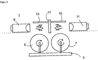
- FIG. 3 shown. In this situation, the already UV-irradiated spindles can be removed by means of the transport device and new spindles to be irradiated are delivered to the irradiation area. When the mirrors are swiveled back into the original orientation, a new irradiation sequence begins.
- the moving means may be configured to allow rotation of the filter about an axis which is outside the beam path.
- the wavelength-selective filter can be designed as an interference filter.
- a UV-reflecting layer system may be provided only on one side of the filter substrate, and an antireflection layer may be provided on the other side of the filter substrate with respect to the UV radiation.
- the filter is moved out of the beam path during the delivery and / or the removal of the substrates substantially.
- the filter can be moved out of the beam path by a rotation about an axis outside the beam path.
- the process can be performed several times and clocked.
Landscapes
- Engineering & Computer Science (AREA)
- Physics & Mathematics (AREA)
- Plasma & Fusion (AREA)
- Life Sciences & Earth Sciences (AREA)
- Microbiology (AREA)
- Mechanical Engineering (AREA)
- General Engineering & Computer Science (AREA)
- General Physics & Mathematics (AREA)
- Optics & Photonics (AREA)
- Toxicology (AREA)
- Health & Medical Sciences (AREA)
- Physical Or Chemical Processes And Apparatus (AREA)
- Exposure And Positioning Against Photoresist Photosensitive Materials (AREA)
- Application Of Or Painting With Fluid Materials (AREA)
- Coating Apparatus (AREA)
- Recrystallisation Techniques (AREA)
- Liquid Crystal (AREA)
Description
- Die vorliegende Erfindung bezieht sich auf ein Verfahren zur UV-Vernetzung von Lackschichten gemäss dem Oberbegriff des Anspruch 1. Die Erfindung bezieht sich ausserdem auf eine Bestrahlungsvorrichtung zur Durchführung des Verfahrens.
- Durch UV-Vernetzung werden auf Substrate aufgebrachte Lacke gehärtet und getrocknet. Der Lack bleibt bis zur Vernetzung fliessfähig und kann nach dem Aufbringen auf ein Substrat schlagartig verfestigt werden.
- Als UV-Strahlungsquelle wird in den meisten Fällen eine Strahlungsquelle verwendet welche sowohl UV Strahlung als auch sichtbares Licht und einen hohen Prozentsatz an Infrarotstrahlung (IR-Strahlung) aussendet. Der hohe Anteil an IR-Strahlung führt zu hohen Prozesstemperaturen welche die zu bestrahlenden Substrate schädigen können. Vor allem wenn es sich bei den belackten Substraten um Kunststoffsubstrate handelt werden mit der herkömmlichen Bestrahlung häufig kritische Temperaturen erreicht. Beispielsweise sollte bei dem unter dem Namen ABS bekannten Kunststoffmaterial Temperaturen von 85°C nicht überschritten werden.
- Gemäss der
DE 3529800 wird dieses Problem dadurch gelöst, dass die Strahlen der UV-Strahlungsquelle derart über einen die Strahlen selektionierenden Spiegel auf das Substrat gerichtet werden, dass das Substrat ausschliesslich von umgelenkten UV-Strahlen beaufschlagt wird, wobei der wärmereichere Anteil der Strahlen den Spiegel geradlinig durchdringt.Figur 1 zeigt den entsprechenden Stand der Technik. Hinter dem Spiegel im Strahlengang durch den Spiegel hindurchgedrungene wärmereiche Anteil der Strahlen wird auf eine Kühlvorrichtung angeordnet. Dafür eignen sich zum Beispiel Kühlrippen, welche Bestandteil der Gehäusewand sind. - Die
DE 3529800 behandelt auch das Problem, dass bei einer Betriebsunterbrechung die Strahlungsquelle möglichst nicht ausgeschaltet werden sollte. Hier wird der Spiegel wenn er in einem Winkel von 45° zur optischen Achse des Strahlenbündels angeordnet ist als um 90° verschwenkbar ausgestaltet, so dass die UV-Strahlung bei einer Betriebsunterbrechung schnell und einfach weggelenkt werden kann. Das UV-reiche Strahlenbündel wird dabei um 180° umgelenkt, so dass es auf die Gehäusewand der Bestrahlungsvorrichtung trifft. - Eine relevante Vorrichtung zum Bestrahlen von Substraten ist auch aus der
WO 98/54525 A1 - Ist lediglich auf einer Seite des Spiegelsubstrates eine UV-reflektierende Schicht realisiert, so kann auf der anderen Seite eine Antireflexionsschicht für sichtbares Licht und für IR-Strahlung über einen weiten Einfallsvvinkelbereich realisiert werden. In diesem Fall sollte aber als Spiegelsubstratmaterial ein spezielles, die UV-Strahlung im Wesentlichen nicht absorbierendes Material gewählt werden. Ansonsten würde beim zweimaligen Durchlaufen des Substrates zu viel UV-Strahlung absorbiert und der Spiegel könnte Schaden nehmen. Wohl auch aus diesem Grund wird in der
DE 3529800 die Strahlungsquelle vorzugsweise auf Halblast geschaltet. Solche die UV-Strahlung nicht absorbierenden Materialien, wie zum Beispiel Quarzglas, sind jedoch teuer. Dies spielt insbesondere bei grossen Vorrichtungen eine Rolle. - Der Erfindung liegt die Aufgabe zugrunde eine Vorrichtung anzugeben, mit der die oben geschilderten Probleme des Stand der Technik zumindest gemildert und vorzugsweise ganz beseitigt werden.
- Die Aufgabe wird erfindungsgemäss dadurch gelöst, dass ausgehend von einer Bestrahlungsvorrichtung wie in
Figur 1 gezeigt, der Kühlvorrichtung 6 zusätzlich als eine die UV-Strahlung absorbierende Vorrichtung ausgestaltet wird. Erfindungsgemäss wird, soll die UV-Bestrahlung der Substrate unterbrochen werden, der Spiegel aus dem Strahlengang der Strahlung herausbewegt. Dies kann beispielsweise durch Rotation des Spiegels um eine Achse, welche ausserhalb des Strahlengangs der Strahlung liegt erreicht werden. - Möglich wäre es auch den Spiegel so zu drehen, dass lediglich die Kanten des Spiegelsubstrates mit Strahlung beaufschlagt werden oder Strahlung mit sehr grossen Einfallswinkeln auf die Substratoberfläche auftrifft und zum Grossteil reflektiert wird aber aufgrund der grossen Einfallswinkel kaum aufgrund dieser Reflexion abgelenkt wird.
- Das Spiegelsubstrat kann nun aus einem die UV-Strahlung absorbierenden Material gemacht sein und es sich auch möglich lediglich auf einer Seite des Spiegelsubstrates eine UV-reflektierende Beschichtung aufzubringen und vorzugsweise die andere Spiegelsubstratseite eine Antireflexionsschicht vorzusehen.
- Gemäss einer bevorzugten Ausführungsform der vorliegenden Erfindung werden die Kanten des Spiegelsubstrates mit der einfallenden Strahlung zumindest teilweise blockierende (absorbierend oder reflektierend) Mitteln versehen.
- Gemäss einer weiteren bevorzugten Ausführungsform werden der Bestrahlungsvorrichtung zu bestrahlende Substrate mittels einer Transportvorrichtung getacktet zugestellt. Dabei ist es von besonderem Vorteil, wenn während des Zustellvorgangs die UV-.Beaufschlagung des Bereichs in den die Substrate zur Bestrahlung positioniert werden unterbrochen wird. Dies kann, ebenfalls getacktet und vorzugsweise mit der Zustellung synchronisiert durch Verschwenken des Spiegels bewerkstelligt werden.
- Gemäss einer weiteren Ausführungsform der vorliegenden Erfindung wird der Spiegel während der UV-Beaufschlagung in Oszillationsbewegung versetzt, wodurch eine homogenere Bestrahlung der Substrate erzielt wird.
- Die Erfindung wird nun anhand eines Beispiels näher erläutert.
-
Figur 1 zeigt eine Bestrahlungsvorrichtung gemäss dem Stand der Technik -
Figur 2 zeigt eine erfindungsgemässe Bestrahlungsvorrichtung im Beaufschlagungsmodus -
Figur 3 zeigt eine erfindungsgemässe Bestrahlungsvorrichtung im Zustellmodus. - Gezeigt in
Figur 2 ist eine erfindungsgemässe Bestrahlungsvorrichtung 1 mit Transportvorrichtung 3 deren Träger als Doppelspindelträger ausgestaltet ist. Auf Spindeln 5, 7 sind die auszuhärtenden Substrate angeordnet, die jedoch aus Gründen der Übersichtlichkeit hier nicht gezeigt sind. Die Bestrahlungsvorrichtung 1 umfasst in diesem Beispiel zwei Strahlungsquellen 9. 11 welche sowohl UV-Strahlung (Pfeile mit gestrichelter Linie) als auch sichtbares Licht und IR-Strahlung aussendet. Im Folgenden wird sichtbares Licht und IR-Strahlung gemeinsam als wärmereiche Strahlung (W-Strahlung) bezeichnet (dargestellt als Pfeile mit durchgezogener Linie). Die Strahlungsquellen 9,11 sind im Beispiel so orientiert, dass deren unabgelenkte Stahlen sich in einer Ebene kreuzen. In dieser Kreuzungsebene wir ein die UV-Strahlung und die W-Strahlung absorbierende Absorberplatte 17 vorgesehen. Vorzugsweise haben die beiden Strahlungsquellen 9,11 eine solche Orientierung, dass sie sich gegenseitig direkt bestrahlen würden, wäre die Absorberplatte nicht vorgesehen. - In die Strahlengänge von den Strahlungsquellen zu der Absorberplatte ist jeweils ein wellenlängenselektiver Spiegel 13, 15 vorgesehen. Die Spiegel sind um 45° gegen die optische Achse der Strahlungsquellen geneigt, so dass sie Strahlung um 90° aus dem ursprünglichen Strahlengang reflektieren. Die Spiegel 13, 15 reflektieren die UV-Strahlung und transmittieren zu einem grossen Teil und vorzugsweise grösstenteils die W-Strahlung. Solche Spiegel können beispielsweise mittels optischen Interferenzfiltern realisiert werden. Besonders vorteilhaft ist es auf einer Seite des Spiegelsubstrates, welches ein normales BK7 Glas sein kann den UV-Reflektor und W-Strahlung Transmitter zu realisieren und auf der anderen Seite eine Breitbandantireflexbeschichtung vorzusehen. Beides ist mittels dünnen Multilagenschichten, welche Interferenz zeigen, machbar.
- In den Strahlengängen der um 90° abgelenkten UV-Strahlung sind die Spindeln 5,7 zugestellt. Bei angeschalteten Strahlungsquellen 9,11 wird somit die W-Strahlung nicht abgelenkt und transmittiert durch die Spiegel 13, 15 hindurch zur Absorberplatte. Demgegenüber wird die UV-Strahlung durch Reflexion an den Spiegeln auf die auf den Spindeln angeordneten Substrate gelenkt. Die Spindeln sind üblicherweise als rotierbare Spindeln ausgestaltet so dass sie während der UV-Bestrahlung die verschiedenen Substrate in die jeweiligen Beaufschlagungszonen rotieren können. Im Beispiel werden die Spiegel 13, 15 mit kleiner Amplitude (z.B. 1°) oszilliert um eine von der Senkrechten auf die Spiegeloberfläche sich unterscheidenden Achse, welche in der durch die optischen Achsen der reflektierte Strahlung und der unabgelenkten Strahlung gebildeten Ebene liegt. Hierdurch erhöht sich die Homogenität der UV-Bestrahlung.
- Um die UV-Bestrahlung zu beenden werden die Spiegel 13, 15 in eine Orientierung geschwenkt, in der die optische Achse der unäbgelenkten Strahlung parallel zu Spiegeloberfläche ist. Dies geschieht vorzugsweise um eine Achse, welche ausserhalb des Strahlengangs der ungestörten Strahlungsquelle liegt. Auf diese Weise propagiert der überwiegende Teil der UV-Strahlung ebenfalls unabgelenkt zur Absorberplatte und wird dort absorbiert. Die dementsprechende Situation ist in
Figur 3 dargestellt. In dieser Situation können mittels der Transportvorrichtung die bereits UV-bestrahlten Spindeln abtransportiert und neue zu bestrahlende Spindeln in den Bestrahlungsbereich zugestellt werden. Mit dem Zurückschwenken der Spiegel in die ursprüngliche Orientierung beginnt dann eine neue Bestrahlungssequenz. - Es wurde gemäss einer bevorzugten Ausführungsform der vorliegenden Erringung eine Bestrahlungsvorrichtung offenbart mit
- zumindest einer Strahlungsquelle welche sowohl UV-Strahlung als auch W-Strahlung, das heisst sichtbares Licht und/oder IR-Strahlung aussendet und
- mit einer Transportvorrichtung zur Zustellung von zu bestrahlenden Substraten und
- zumindest einem unter einem Winkel von 45° die UV-Strahlung reflektierende und W-Strahlung transmittierende wellenlängenselektives Filter
- mit Mittel zur Absorption von IR-Strahlung welche in Propagationsrichtung dem optischen Filter nachgeordnet in dem Strahlengang der vom wellenlängenselektiven Filter nicht abgelenkten W-Strahlung angeordnet ist
- Die Bewegungsmittel können so ausgestaltet sein, dass sie eine Rotation des Filters um eine Achse erlauben, welche ausserhalb des Strahlengangs liegt.
- Das wellenlängenselektive Filter kann als Interferenzfilter ausgebildet sein. Es kann beispielsweise lediglich auf einer Seite des Filtersubstrates ein UV-reflektierendes Schichtsystem vorgesehen ist und es kann auf der anderen Seite des Filtersubstrates bezüglich der W-Strahlung ein Antireflexschicht vorgesehen sein.
- Es wurde ein Verfahren zur Beaufschlagung von Substraten mit UV-Strahlung offenbart umfassend die Schritte:
- Bereitstellung einer Strahlungsquelle welche UV-Strahlung und W-Strahlung aussendet
- Separation der UV-Strahlung von der W-Strahlung mittels Transmission der W-Strahlung durch ein wellenlängenselektives Filter und Reflexion der UV-Strahlung an dem wellenlängenselektiven Filter
- Bereitstellung von Absorptionsmitteln welche vom wellenlängenselektiven Filter nicht abgelenkte Strahlung absorbieren
- Zustellung der Substrate in den für die UV-Beaufschlagung vorgesehenen Bereich
- Abtransport der mit UV-Strahlung beaufschlagten Substrate,
- Bei dem Verfahren wird das Filter während der Zustellung und/oder des Abtransports der Substrate im Wesentlichen aus dem Strahlengang herausbewegt wird.
- Das Filter kann durch eine Rotation um eine Achse ausserhalb des Strahlengangs aus dem Strahlengang bewegt wird. Das Verfahren kann mehrmals und getaktet durchgeführt wird.
Claims (9)
- Bestrahlungsvorrichtung mit- zumindest einer Strahlungsquelle welche sowohl UV-Strahlung als auch W-Strahlung, das heisst sichtbares Licht und/oder IR-Strahlung aussendet und- mit einer Transportvorrichtung zur Zustellung von zu bestrahlenden Substraten und- zumindest einem unter einem Winkel von 45° die UV-Strahlung reflektierende und W-Strahlung transmittierende wellenlängenselektives Filter- mit Mittel zur Absorption von IR-Strahlung welche in Propagationsrichtung dem optischen Filter nachgeordnet in dem Strahlengang der vom wellenlängenselektiven Filter nicht abgelenkten W-Strahlung angeordnet istdadurch gekennzeichnet, dass die Mittel zur Absorption von IR-Strahlung auch als Mittel zur Absorption von sichtbarem Licht und von UV-Strahlen ausgebildet sind und dass die Bestrahlungsvorrichtung Bewegungsmittel umfasst, um das wellenlängenselektive Filter in den Strahlengang der Strahlungsquelle hinein zu führen und aus diesem herauszuführen
- Bestahlungsvorrichtung nach Anspruch 1, dadurch gekennzeichnet, dass die Bewegungsmittel eine Rotation des Filters um eine Achse erlauben, welche ausserhalb des Strahlengangs liegt.
- Berstrahlungsvorrichtung nach einem der vorangehenden Ansprüche, dadurch gekennzeichnet, dass das wellenlängenselektive Filter als Interferenzfilter ausgebildet ist.
- Bestrahlungsvorrichtung nach einem der vorangehenden Ansprüche, dadurch gekennzeichnet, dass lediglich auf einer Seite des Filtersubstrates ein UV-reflektierendes Schichtsystem vorgesehen ist.
- Bestrahlungsvorrichtung nach Anspruch 4 dadurch gekennzeichnet, dass auf der anderen Seite des Filtersubstrates bezüglich der W-Strahlung ein Antireflexschicht vorgesehen ist.
- Verfahren zur Beaufschlagung von Substraten mit UV-Strahlung umfassend die Schritte:- Bereitstellung einer Strahlungsquelle welche UV-Strahlung und W-Strahlung aussendet- Separation der UV-Strahlung von der W-Strahlung mittels Transmission der W-Strahlung durch ein wellenlängenselektives Filter und Reflexion der UV-Strahlung an dem wellenlängenselektiven Filter- Bereitstellung von Absorptionsmitteln welche vom wellenlängenselektiven Filter nicht abgelenkte Strahlung absorbieren- Zustellung der Substrate in den für die UV-Beaufschlagung vorgesehenen Bereich- Abtransport der mit UV-Strahlung beaufschlagten Substratedadurch gekennzeichnet, dass vor der Zustellung und/oder des Abtransportes der Substrate das wellenlängenselektive Filter in seiner Orientierung und/oder Position verändert wird dergestalt, dass während der Zustellung und/oder des Abtransportes der Substrate die UV-Strahlung nicht vom wellenlängenselektiven Filter reflektiert wird und daher auf die Absorptionsmittel auftrifft und von diesen absorbiert wird.
- Verfahren nach Anspruch 6, dadurch gekennzeichnet, dass das Filter während der Zustellung und/oder des Abtransports der Substrate im Wesentlichen aus dem Strahlengang herausbewegt wird.
- Verfahren nach Anspruch 7, dadurch gekennzeichnet, dass das Filter durch eine Rotation um eine Achse ausserhalb des Strahlengangs aus dem Strahlengang bewegt wird.
- Verfahren nach einem der Ansprüche 6 bis 8, dadurch gekennzeichnet dass das Verfahren mehrmals und getaktet durchgeführt wird.
Priority Applications (1)
| Application Number | Priority Date | Filing Date | Title |
|---|---|---|---|
| PL13783254T PL2911808T3 (pl) | 2012-10-23 | 2013-10-22 | Urządzenie do napromieniowywania promieniami UV dla taktowanego trybu pracy |
Applications Claiming Priority (2)
| Application Number | Priority Date | Filing Date | Title |
|---|---|---|---|
| DE102012020743.3A DE102012020743A1 (de) | 2012-10-23 | 2012-10-23 | UV-Bestrahlungsvorrichtung für den getakteten Betrieb |
| PCT/EP2013/003176 WO2014063809A1 (de) | 2012-10-23 | 2013-10-22 | Uv-bestrahlungsvorrichtung für den getakteten betrieb |
Publications (3)
| Publication Number | Publication Date |
|---|---|
| EP2911808A1 EP2911808A1 (de) | 2015-09-02 |
| EP2911808B1 true EP2911808B1 (de) | 2018-02-21 |
| EP2911808B8 EP2911808B8 (de) | 2018-05-02 |
Family
ID=49488545
Family Applications (1)
| Application Number | Title | Priority Date | Filing Date |
|---|---|---|---|
| EP13783254.9A Not-in-force EP2911808B8 (de) | 2012-10-23 | 2013-10-22 | Uv-bestrahlungsvorrichtung für den getakteten betrieb |
Country Status (11)
| Country | Link |
|---|---|
| US (1) | US9517490B2 (de) |
| EP (1) | EP2911808B8 (de) |
| JP (1) | JP6284535B2 (de) |
| KR (2) | KR20210119540A (de) |
| CN (1) | CN105050733B (de) |
| DE (1) | DE102012020743A1 (de) |
| ES (1) | ES2666579T3 (de) |
| HU (1) | HUE036974T2 (de) |
| PL (1) | PL2911808T3 (de) |
| PT (1) | PT2911808T (de) |
| WO (1) | WO2014063809A1 (de) |
Family Cites Families (24)
| Publication number | Priority date | Publication date | Assignee | Title |
|---|---|---|---|---|
| JPS4910735A (de) * | 1972-05-26 | 1974-01-30 | ||
| GB1550096A (en) * | 1976-02-23 | 1979-08-08 | Nath G | Uv irradiation device |
| JPH0646304B2 (ja) * | 1984-07-31 | 1994-06-15 | 東芝ライテック株式会社 | 紫外線硬化用照射装置 |
| CH660489A5 (de) | 1984-08-31 | 1987-04-30 | Bernhard Glaus | Verfahren und vorrichtung zum aushaerten polymerisierbarer beschichtungsmassen auf nicht textilen substraten. |
| US4864145A (en) * | 1986-10-31 | 1989-09-05 | Burgio Joseph T Jr | Apparatus and method for curing photosensitive coatings |
| JPH07111583B2 (ja) * | 1989-04-21 | 1995-11-29 | 株式会社オーク製作所 | 入射角可変用露光装置 |
| JP2668271B2 (ja) * | 1989-11-08 | 1997-10-27 | 株式会社オーク製作所 | 露光焼付装置用光源ユニット |
| JP3433760B2 (ja) * | 1993-05-14 | 2003-08-04 | ソニー株式会社 | 光ディスクの保護膜機 |
| US5441531A (en) * | 1993-10-18 | 1995-08-15 | Dusa Pharmaceuticals Inc. | Illuminator and methods for photodynamic therapy |
| US5595118A (en) * | 1995-10-16 | 1997-01-21 | F & L Machinery Design, Inc. | Drying apparatus for a dry off-set printing press having an ultra-violet lamp assembly |
| JP3094902B2 (ja) * | 1996-03-27 | 2000-10-03 | ウシオ電機株式会社 | 紫外線照射装置 |
| DE59805621D1 (de) * | 1997-05-26 | 2003-11-20 | Bernhard Max Glaus | Vorrichtung zum bestrahlen eines substrats mittels uv-strahlen und verfahren zum betrieb der vorrichtung |
| DE19810455C2 (de) * | 1998-03-11 | 2000-02-24 | Michael Bisges | Kaltlicht-UV-Bestrahlungsvorrichtung |
| CN1150973C (zh) * | 1998-07-03 | 2004-05-26 | 中外制药株式会社 | 光化学反应用紫外线照射装置以及使用它的维生素d衍生物的制备方法 |
| DE19962144A1 (de) * | 1999-12-22 | 2001-06-28 | Schott Desag Ag | UV-reflektierendes Interferenzschichtsystem |
| EP1264135B1 (de) * | 2000-03-13 | 2007-05-23 | Corrosion Consultants, Inc. | Kombination einer uv-inspektionslampe mit einer taschenlampe |
| DE10243577B4 (de) * | 2002-09-19 | 2008-08-07 | Eltosch Torsten Schmidt Gmbh | Bestrahlungseinrichtung und Verwendung einer solchen |
| US6834984B2 (en) * | 2002-10-15 | 2004-12-28 | Delaware Captial Formation, Inc. | Curved reflective surface for redirecting light to bypass a light source coupled with a hot mirror |
| US6883936B2 (en) * | 2002-10-15 | 2005-04-26 | Delaware Capital Formation, Inc. | Shutter apparatus, curing lamp housing incorporating same, and method of shutter replacement |
| JP4971137B2 (ja) * | 2004-04-08 | 2012-07-11 | フェデラル−モーグル コーポレイション | 色収差補正搭載プロジェクタ・ランプ・ヘッドライト |
| DE502005008677D1 (de) * | 2004-05-04 | 2010-01-21 | Eltosch Torsten Schmidt Gmbh | Bestrahlungseinrichtung |
| US7438468B2 (en) * | 2004-11-12 | 2008-10-21 | Applied Materials, Inc. | Multiple band pass filtering for pyrometry in laser based annealing systems |
| JP5533304B2 (ja) * | 2010-06-11 | 2014-06-25 | セイコーエプソン株式会社 | 液滴吐出装置 |
| US9157642B2 (en) * | 2010-10-12 | 2015-10-13 | Lg Innotek Co., Ltd. | Air conditioner including virus removal device |
-
2012
- 2012-10-23 DE DE102012020743.3A patent/DE102012020743A1/de not_active Withdrawn
-
2013
- 2013-10-22 EP EP13783254.9A patent/EP2911808B8/de not_active Not-in-force
- 2013-10-22 ES ES13783254.9T patent/ES2666579T3/es active Active
- 2013-10-22 KR KR1020217029509A patent/KR20210119540A/ko not_active Abandoned
- 2013-10-22 US US14/437,934 patent/US9517490B2/en not_active Expired - Fee Related
- 2013-10-22 PT PT137832549T patent/PT2911808T/pt unknown
- 2013-10-22 CN CN201380067452.5A patent/CN105050733B/zh not_active Expired - Fee Related
- 2013-10-22 HU HUE13783254A patent/HUE036974T2/hu unknown
- 2013-10-22 PL PL13783254T patent/PL2911808T3/pl unknown
- 2013-10-22 KR KR1020157012877A patent/KR102440917B1/ko not_active Expired - Fee Related
- 2013-10-22 WO PCT/EP2013/003176 patent/WO2014063809A1/de not_active Ceased
- 2013-10-22 JP JP2015538325A patent/JP6284535B2/ja not_active Expired - Fee Related
Non-Patent Citations (1)
| Title |
|---|
| None * |
Also Published As
| Publication number | Publication date |
|---|---|
| KR102440917B1 (ko) | 2022-09-06 |
| PL2911808T3 (pl) | 2018-10-31 |
| US9517490B2 (en) | 2016-12-13 |
| JP6284535B2 (ja) | 2018-02-28 |
| WO2014063809A1 (de) | 2014-05-01 |
| ES2666579T3 (es) | 2018-05-07 |
| EP2911808A1 (de) | 2015-09-02 |
| KR20150074074A (ko) | 2015-07-01 |
| CN105050733A (zh) | 2015-11-11 |
| EP2911808B8 (de) | 2018-05-02 |
| KR20210119540A (ko) | 2021-10-05 |
| US20150375263A1 (en) | 2015-12-31 |
| PT2911808T (pt) | 2018-05-11 |
| CN105050733B (zh) | 2017-11-07 |
| JP2016505348A (ja) | 2016-02-25 |
| DE102012020743A1 (de) | 2014-04-24 |
| HUE036974T2 (hu) | 2018-08-28 |
Similar Documents
| Publication | Publication Date | Title |
|---|---|---|
| DE3529800A1 (de) | Verfahren und vorrichtung zur uv-polymerisation von beschichtungsmassen | |
| DE2639728A1 (de) | Verfahren und vorrichtung zum behandeln eines substrats mit ultraviolettstrahlung | |
| EP2234851B1 (de) | Optische regensensorvorrichtung für ein kraftfahrzeug | |
| EP3331652A1 (de) | Uv-bestrahlungsaggregat zur strahlungshärtung | |
| WO2005011878A2 (de) | Vorrichtung zur aushärtung einer aus einem material, das unter elektromagnetischer strahlung aushärtet, insbesondere aus einem uv-lack oder aus einem thermisch aushärtenden lack, bestehenden beschichtung eines gegenstandes | |
| WO2008125375A1 (de) | Vorrichtung zum aktivieren einer polymerisierbaren masse | |
| EP2171542B1 (de) | Verfahren und vorrichtung zur herstellung von strukturierten optischen materialien | |
| DE102007063603B4 (de) | Verfahren und Vorrichtung zur Herstellung von keramischen Folien mit UV-LED | |
| DE4436713A1 (de) | Vorrichtung zur Trocknung der Oberflächen eines Gegenstandes | |
| DE10106888B4 (de) | Verfahren und Vorrichtung zur Herstellung einer Oberflächenbeschichtung | |
| WO2014063809A1 (de) | Uv-bestrahlungsvorrichtung für den getakteten betrieb | |
| EP3016751B1 (de) | Wärme-lichttrennung für eine uv-strahlungsquelle | |
| DE10352184A1 (de) | Vorrichtung zum Härten und/oder Trocknen einer Beschichtung auf einem Substrat | |
| EP2538186B1 (de) | Variable Laufzeitänderung von elektromagnetischer Strahlung | |
| DE4413158A1 (de) | Vorrichtung zum großflächigen und umweltschonenden Entfernen einer Schicht aus Lack oder Kunststoff, beispielsweise Polytetrafluoräthylen | |
| DE102006035986B4 (de) | Vorrichtung zum Trocknen von UV-Druckfarben oder UV-Lacken auf einem Bedruckstoff | |
| DE102008061597B4 (de) | UV-Bestrahlungsvorrichtung | |
| EP2180484B1 (de) | Strahlungsoptisches Bauelement zur Beeinflussung von Strahlung in Bezug auf deren Wellenlängenspektrum | |
| EP1909136A2 (de) | Belichtungsstation | |
| WO2003074193A2 (de) | Verfahren und vorrichtung zur herstellung einer oberflächenbeschichtung durch nir- und uv-nachbehandlung | |
| EP0930104B1 (de) | Verfahren und Vorrichtung zum Vernetzen und Härten von Lack | |
| EP2379233A1 (de) | Verfahren zum beschichten eines bauteils | |
| DE102010018704A1 (de) | Vorrichtung und Verfahren zum Härten einer Beschichtung eines Bauteils | |
| EP1593919A2 (de) | Verfahren und Vorrichtung zur Härtung von radikalisch polymerisierbaren Beschichtungen | |
| DE102016100144A1 (de) | Vorrichtung zum Beschichten einer Faser sowie Verfahren zum Beschichten einer Faser und Faser |
Legal Events
| Date | Code | Title | Description |
|---|---|---|---|
| PUAI | Public reference made under article 153(3) epc to a published international application that has entered the european phase |
Free format text: ORIGINAL CODE: 0009012 |
|
| 17P | Request for examination filed |
Effective date: 20150508 |
|
| AK | Designated contracting states |
Kind code of ref document: A1 Designated state(s): AL AT BE BG CH CY CZ DE DK EE ES FI FR GB GR HR HU IE IS IT LI LT LU LV MC MK MT NL NO PL PT RO RS SE SI SK SM TR |
|
| AX | Request for extension of the european patent |
Extension state: BA ME |
|
| DAX | Request for extension of the european patent (deleted) | ||
| 17Q | First examination report despatched |
Effective date: 20160428 |
|
| GRAP | Despatch of communication of intention to grant a patent |
Free format text: ORIGINAL CODE: EPIDOSNIGR1 |
|
| RIC1 | Information provided on ipc code assigned before grant |
Ipc: B05D 3/06 20060101AFI20171002BHEP Ipc: B01J 19/12 20060101ALI20171002BHEP Ipc: G02B 5/20 20060101ALI20171002BHEP Ipc: G02B 5/28 20060101ALI20171002BHEP Ipc: F26B 3/28 20060101ALI20171002BHEP |
|
| INTG | Intention to grant announced |
Effective date: 20171019 |
|
| GRAS | Grant fee paid |
Free format text: ORIGINAL CODE: EPIDOSNIGR3 |
|
| GRAA | (expected) grant |
Free format text: ORIGINAL CODE: 0009210 |
|
| AK | Designated contracting states |
Kind code of ref document: B1 Designated state(s): AL AT BE BG CH CY CZ DE DK EE ES FI FR GB GR HR HU IE IS IT LI LT LU LV MC MK MT NL NO PL PT RO RS SE SI SK SM TR |
|
| REG | Reference to a national code |
Ref country code: GB Ref legal event code: FG4D Free format text: NOT ENGLISH |
|
| REG | Reference to a national code |
Ref country code: CH Ref legal event code: EP |
|
| REG | Reference to a national code |
Ref country code: DE Ref legal event code: R096 Ref document number: 502013009492 Country of ref document: DE Ref country code: AT Ref legal event code: REF Ref document number: 971139 Country of ref document: AT Kind code of ref document: T Effective date: 20180315 |
|
| REG | Reference to a national code |
Ref country code: IE Ref legal event code: FG4D Free format text: LANGUAGE OF EP DOCUMENT: GERMAN |
|
| RAP2 | Party data changed (patent owner data changed or rights of a patent transferred) |
Owner name: OERLIKON SURFACE SOLUTIONS AG, PFAEFFIKON |
|
| REG | Reference to a national code |
Ref country code: ES Ref legal event code: FG2A Ref document number: 2666579 Country of ref document: ES Kind code of ref document: T3 Effective date: 20180507 |
|
| REG | Reference to a national code |
Ref country code: RO Ref legal event code: EPE Ref country code: PT Ref legal event code: SC4A Ref document number: 2911808 Country of ref document: PT Date of ref document: 20180511 Kind code of ref document: T Free format text: AVAILABILITY OF NATIONAL TRANSLATION Effective date: 20180504 |
|
| REG | Reference to a national code |
Ref country code: NL Ref legal event code: FP |
|
| REG | Reference to a national code |
Ref country code: SE Ref legal event code: TRGR |
|
| REG | Reference to a national code |
Ref country code: LT Ref legal event code: MG4D |
|
| REG | Reference to a national code |
Ref country code: BE Ref legal event code: HC Owner name: OERLIKON SURFACE SOLUTIONS AG, PFAEFFIKON; CH Free format text: DETAILS ASSIGNMENT: CHANGE OF OWNER(S), CHANGEMENT DE NOM DU PROPRIETAIRE; FORMER OWNER NAME: OERLIKON SURFACE SOLUTIONS AG, TRUEBBACH Effective date: 20180425 |
|
| PG25 | Lapsed in a contracting state [announced via postgrant information from national office to epo] |
Ref country code: HR Free format text: LAPSE BECAUSE OF FAILURE TO SUBMIT A TRANSLATION OF THE DESCRIPTION OR TO PAY THE FEE WITHIN THE PRESCRIBED TIME-LIMIT Effective date: 20180221 Ref country code: NO Free format text: LAPSE BECAUSE OF FAILURE TO SUBMIT A TRANSLATION OF THE DESCRIPTION OR TO PAY THE FEE WITHIN THE PRESCRIBED TIME-LIMIT Effective date: 20180521 Ref country code: LT Free format text: LAPSE BECAUSE OF FAILURE TO SUBMIT A TRANSLATION OF THE DESCRIPTION OR TO PAY THE FEE WITHIN THE PRESCRIBED TIME-LIMIT Effective date: 20180221 Ref country code: CY Free format text: LAPSE BECAUSE OF FAILURE TO SUBMIT A TRANSLATION OF THE DESCRIPTION OR TO PAY THE FEE WITHIN THE PRESCRIBED TIME-LIMIT Effective date: 20180221 |
|
| REG | Reference to a national code |
Ref country code: HU Ref legal event code: AG4A Ref document number: E036974 Country of ref document: HU |
|
| PG25 | Lapsed in a contracting state [announced via postgrant information from national office to epo] |
Ref country code: BG Free format text: LAPSE BECAUSE OF FAILURE TO SUBMIT A TRANSLATION OF THE DESCRIPTION OR TO PAY THE FEE WITHIN THE PRESCRIBED TIME-LIMIT Effective date: 20180521 Ref country code: LV Free format text: LAPSE BECAUSE OF FAILURE TO SUBMIT A TRANSLATION OF THE DESCRIPTION OR TO PAY THE FEE WITHIN THE PRESCRIBED TIME-LIMIT Effective date: 20180221 Ref country code: GR Free format text: LAPSE BECAUSE OF FAILURE TO SUBMIT A TRANSLATION OF THE DESCRIPTION OR TO PAY THE FEE WITHIN THE PRESCRIBED TIME-LIMIT Effective date: 20180522 Ref country code: RS Free format text: LAPSE BECAUSE OF FAILURE TO SUBMIT A TRANSLATION OF THE DESCRIPTION OR TO PAY THE FEE WITHIN THE PRESCRIBED TIME-LIMIT Effective date: 20180221 |
|
| PG25 | Lapsed in a contracting state [announced via postgrant information from national office to epo] |
Ref country code: MT Free format text: LAPSE BECAUSE OF FAILURE TO SUBMIT A TRANSLATION OF THE DESCRIPTION OR TO PAY THE FEE WITHIN THE PRESCRIBED TIME-LIMIT Effective date: 20180221 |
|
| REG | Reference to a national code |
Ref country code: FR Ref legal event code: PLFP Year of fee payment: 6 |
|
| PG25 | Lapsed in a contracting state [announced via postgrant information from national office to epo] |
Ref country code: EE Free format text: LAPSE BECAUSE OF FAILURE TO SUBMIT A TRANSLATION OF THE DESCRIPTION OR TO PAY THE FEE WITHIN THE PRESCRIBED TIME-LIMIT Effective date: 20180221 Ref country code: AL Free format text: LAPSE BECAUSE OF FAILURE TO SUBMIT A TRANSLATION OF THE DESCRIPTION OR TO PAY THE FEE WITHIN THE PRESCRIBED TIME-LIMIT Effective date: 20180221 |
|
| REG | Reference to a national code |
Ref country code: SK Ref legal event code: T3 Ref document number: E 28033 Country of ref document: SK |
|
| REG | Reference to a national code |
Ref country code: DE Ref legal event code: R097 Ref document number: 502013009492 Country of ref document: DE |
|
| PG25 | Lapsed in a contracting state [announced via postgrant information from national office to epo] |
Ref country code: SM Free format text: LAPSE BECAUSE OF FAILURE TO SUBMIT A TRANSLATION OF THE DESCRIPTION OR TO PAY THE FEE WITHIN THE PRESCRIBED TIME-LIMIT Effective date: 20180221 Ref country code: DK Free format text: LAPSE BECAUSE OF FAILURE TO SUBMIT A TRANSLATION OF THE DESCRIPTION OR TO PAY THE FEE WITHIN THE PRESCRIBED TIME-LIMIT Effective date: 20180221 |
|
| PLBE | No opposition filed within time limit |
Free format text: ORIGINAL CODE: 0009261 |
|
| STAA | Information on the status of an ep patent application or granted ep patent |
Free format text: STATUS: NO OPPOSITION FILED WITHIN TIME LIMIT |
|
| 26N | No opposition filed |
Effective date: 20181122 |
|
| PG25 | Lapsed in a contracting state [announced via postgrant information from national office to epo] |
Ref country code: SI Free format text: LAPSE BECAUSE OF FAILURE TO SUBMIT A TRANSLATION OF THE DESCRIPTION OR TO PAY THE FEE WITHIN THE PRESCRIBED TIME-LIMIT Effective date: 20180221 |
|
| PG25 | Lapsed in a contracting state [announced via postgrant information from national office to epo] |
Ref country code: MC Free format text: LAPSE BECAUSE OF FAILURE TO SUBMIT A TRANSLATION OF THE DESCRIPTION OR TO PAY THE FEE WITHIN THE PRESCRIBED TIME-LIMIT Effective date: 20180221 |
|
| REG | Reference to a national code |
Ref country code: IE Ref legal event code: MM4A |
|
| PG25 | Lapsed in a contracting state [announced via postgrant information from national office to epo] |
Ref country code: IE Free format text: LAPSE BECAUSE OF NON-PAYMENT OF DUE FEES Effective date: 20181022 |
|
| PG25 | Lapsed in a contracting state [announced via postgrant information from national office to epo] |
Ref country code: MK Free format text: LAPSE BECAUSE OF NON-PAYMENT OF DUE FEES Effective date: 20180221 |
|
| PG25 | Lapsed in a contracting state [announced via postgrant information from national office to epo] |
Ref country code: IS Free format text: LAPSE BECAUSE OF FAILURE TO SUBMIT A TRANSLATION OF THE DESCRIPTION OR TO PAY THE FEE WITHIN THE PRESCRIBED TIME-LIMIT Effective date: 20180621 |
|
| PGFP | Annual fee paid to national office [announced via postgrant information from national office to epo] |
Ref country code: NL Payment date: 20211026 Year of fee payment: 9 |
|
| PGFP | Annual fee paid to national office [announced via postgrant information from national office to epo] |
Ref country code: FI Payment date: 20211019 Year of fee payment: 9 Ref country code: ES Payment date: 20211117 Year of fee payment: 9 Ref country code: LU Payment date: 20211026 Year of fee payment: 9 Ref country code: SE Payment date: 20211022 Year of fee payment: 9 Ref country code: SK Payment date: 20211006 Year of fee payment: 9 Ref country code: PT Payment date: 20211004 Year of fee payment: 9 Ref country code: TR Payment date: 20211005 Year of fee payment: 9 Ref country code: RO Payment date: 20211014 Year of fee payment: 9 Ref country code: GB Payment date: 20211026 Year of fee payment: 9 Ref country code: CZ Payment date: 20211022 Year of fee payment: 9 Ref country code: AT Payment date: 20211019 Year of fee payment: 9 |
|
| PGFP | Annual fee paid to national office [announced via postgrant information from national office to epo] |
Ref country code: IT Payment date: 20211020 Year of fee payment: 9 Ref country code: HU Payment date: 20211006 Year of fee payment: 9 Ref country code: FR Payment date: 20211027 Year of fee payment: 9 Ref country code: CH Payment date: 20211022 Year of fee payment: 9 Ref country code: BE Payment date: 20211026 Year of fee payment: 9 |
|
| PGFP | Annual fee paid to national office [announced via postgrant information from national office to epo] |
Ref country code: PL Payment date: 20211007 Year of fee payment: 9 |
|
| PGFP | Annual fee paid to national office [announced via postgrant information from national office to epo] |
Ref country code: DE Payment date: 20211228 Year of fee payment: 9 |
|
| REG | Reference to a national code |
Ref country code: DE Ref legal event code: R119 Ref document number: 502013009492 Country of ref document: DE |
|
| REG | Reference to a national code |
Ref country code: SE Ref legal event code: EUG |
|
| REG | Reference to a national code |
Ref country code: CH Ref legal event code: PL Ref country code: SK Ref legal event code: MM4A Ref document number: E 28033 Country of ref document: SK Effective date: 20221022 |
|
| REG | Reference to a national code |
Ref country code: NL Ref legal event code: MM Effective date: 20221101 |
|
| REG | Reference to a national code |
Ref country code: AT Ref legal event code: MM01 Ref document number: 971139 Country of ref document: AT Kind code of ref document: T Effective date: 20221022 |
|
| REG | Reference to a national code |
Ref country code: BE Ref legal event code: MM Effective date: 20221031 |
|
| GBPC | Gb: european patent ceased through non-payment of renewal fee |
Effective date: 20221022 |
|
| PG25 | Lapsed in a contracting state [announced via postgrant information from national office to epo] |
Ref country code: LU Free format text: LAPSE BECAUSE OF NON-PAYMENT OF DUE FEES Effective date: 20221022 |
|
| PG25 | Lapsed in a contracting state [announced via postgrant information from national office to epo] |
Ref country code: RO Free format text: LAPSE BECAUSE OF NON-PAYMENT OF DUE FEES Effective date: 20221022 Ref country code: PT Free format text: LAPSE BECAUSE OF NON-PAYMENT OF DUE FEES Effective date: 20230424 Ref country code: NL Free format text: LAPSE BECAUSE OF NON-PAYMENT OF DUE FEES Effective date: 20221101 Ref country code: LI Free format text: LAPSE BECAUSE OF NON-PAYMENT OF DUE FEES Effective date: 20221031 Ref country code: HU Free format text: LAPSE BECAUSE OF NON-PAYMENT OF DUE FEES Effective date: 20221023 Ref country code: FR Free format text: LAPSE BECAUSE OF NON-PAYMENT OF DUE FEES Effective date: 20221031 Ref country code: DE Free format text: LAPSE BECAUSE OF NON-PAYMENT OF DUE FEES Effective date: 20230503 Ref country code: CZ Free format text: LAPSE BECAUSE OF NON-PAYMENT OF DUE FEES Effective date: 20221022 Ref country code: CH Free format text: LAPSE BECAUSE OF NON-PAYMENT OF DUE FEES Effective date: 20221031 Ref country code: AT Free format text: LAPSE BECAUSE OF NON-PAYMENT OF DUE FEES Effective date: 20221022 |
|
| PG25 | Lapsed in a contracting state [announced via postgrant information from national office to epo] |
Ref country code: SK Free format text: LAPSE BECAUSE OF NON-PAYMENT OF DUE FEES Effective date: 20221022 Ref country code: SE Free format text: LAPSE BECAUSE OF NON-PAYMENT OF DUE FEES Effective date: 20221023 |
|
| PG25 | Lapsed in a contracting state [announced via postgrant information from national office to epo] |
Ref country code: BE Free format text: LAPSE BECAUSE OF NON-PAYMENT OF DUE FEES Effective date: 20221031 |
|
| PG25 | Lapsed in a contracting state [announced via postgrant information from national office to epo] |
Ref country code: IT Free format text: LAPSE BECAUSE OF NON-PAYMENT OF DUE FEES Effective date: 20221022 Ref country code: GB Free format text: LAPSE BECAUSE OF NON-PAYMENT OF DUE FEES Effective date: 20221022 |
|
| PG25 | Lapsed in a contracting state [announced via postgrant information from national office to epo] |
Ref country code: PL Free format text: LAPSE BECAUSE OF NON-PAYMENT OF DUE FEES Effective date: 20221022 |
|
| REG | Reference to a national code |
Ref country code: ES Ref legal event code: FD2A Effective date: 20231201 |
|
| PG25 | Lapsed in a contracting state [announced via postgrant information from national office to epo] |
Ref country code: ES Free format text: LAPSE BECAUSE OF NON-PAYMENT OF DUE FEES Effective date: 20221023 |
|
| PG25 | Lapsed in a contracting state [announced via postgrant information from national office to epo] |
Ref country code: ES Free format text: LAPSE BECAUSE OF NON-PAYMENT OF DUE FEES Effective date: 20221023 |
|
| PG25 | Lapsed in a contracting state [announced via postgrant information from national office to epo] |
Ref country code: FI Free format text: LAPSE BECAUSE OF NON-PAYMENT OF DUE FEES Effective date: 20221022 |
|
| PG25 | Lapsed in a contracting state [announced via postgrant information from national office to epo] |
Ref country code: TR Free format text: LAPSE BECAUSE OF NON-PAYMENT OF DUE FEES Effective date: 20221022 |