EP2910773B1 - Connexion pour pale de rotor - Google Patents
Connexion pour pale de rotor Download PDFInfo
- Publication number
- EP2910773B1 EP2910773B1 EP15156312.9A EP15156312A EP2910773B1 EP 2910773 B1 EP2910773 B1 EP 2910773B1 EP 15156312 A EP15156312 A EP 15156312A EP 2910773 B1 EP2910773 B1 EP 2910773B1
- Authority
- EP
- European Patent Office
- Prior art keywords
- rotor blade
- connection
- rotor
- transverse
- blade
- Prior art date
- Legal status (The legal status is an assumption and is not a legal conclusion. Google has not performed a legal analysis and makes no representation as to the accuracy of the status listed.)
- Not-in-force
Links
- 229910052751 metal Inorganic materials 0.000 claims description 30
- 239000002184 metal Substances 0.000 claims description 30
- 239000000463 material Substances 0.000 claims description 21
- 229920002430 Fibre-reinforced plastic Polymers 0.000 claims description 13
- 239000011151 fibre-reinforced plastic Substances 0.000 claims description 13
- 239000012779 reinforcing material Substances 0.000 claims description 11
- 239000000835 fiber Substances 0.000 claims description 5
- 238000004519 manufacturing process Methods 0.000 description 8
- 230000007704 transition Effects 0.000 description 8
- 239000011152 fibreglass Substances 0.000 description 6
- 229910000831 Steel Inorganic materials 0.000 description 5
- 238000005538 encapsulation Methods 0.000 description 5
- 239000010959 steel Substances 0.000 description 5
- 238000005452 bending Methods 0.000 description 4
- 229920003023 plastic Polymers 0.000 description 4
- 239000004033 plastic Substances 0.000 description 4
- 238000009826 distribution Methods 0.000 description 3
- 239000011888 foil Substances 0.000 description 3
- 239000003365 glass fiber Substances 0.000 description 3
- 238000000034 method Methods 0.000 description 3
- 238000004026 adhesive bonding Methods 0.000 description 2
- 238000010276 construction Methods 0.000 description 2
- 230000007423 decrease Effects 0.000 description 2
- 229920000049 Carbon (fiber) Polymers 0.000 description 1
- RTAQQCXQSZGOHL-UHFFFAOYSA-N Titanium Chemical compound [Ti] RTAQQCXQSZGOHL-UHFFFAOYSA-N 0.000 description 1
- 239000000853 adhesive Substances 0.000 description 1
- 230000001070 adhesive effect Effects 0.000 description 1
- 229910052782 aluminium Inorganic materials 0.000 description 1
- XAGFODPZIPBFFR-UHFFFAOYSA-N aluminium Chemical compound [Al] XAGFODPZIPBFFR-UHFFFAOYSA-N 0.000 description 1
- 238000005422 blasting Methods 0.000 description 1
- 239000004917 carbon fiber Substances 0.000 description 1
- 230000001427 coherent effect Effects 0.000 description 1
- 239000002131 composite material Substances 0.000 description 1
- 230000007797 corrosion Effects 0.000 description 1
- 238000005260 corrosion Methods 0.000 description 1
- 230000007547 defect Effects 0.000 description 1
- 230000002349 favourable effect Effects 0.000 description 1
- 239000011521 glass Substances 0.000 description 1
- 238000001802 infusion Methods 0.000 description 1
- 238000005304 joining Methods 0.000 description 1
- 239000002648 laminated material Substances 0.000 description 1
- 238000000465 moulding Methods 0.000 description 1
- 230000008092 positive effect Effects 0.000 description 1
- 238000003825 pressing Methods 0.000 description 1
- 239000011347 resin Substances 0.000 description 1
- 229920005989 resin Polymers 0.000 description 1
- 239000010936 titanium Substances 0.000 description 1
- 229910052719 titanium Inorganic materials 0.000 description 1
- 238000009827 uniform distribution Methods 0.000 description 1
Images


Classifications
-
- F—MECHANICAL ENGINEERING; LIGHTING; HEATING; WEAPONS; BLASTING
- F03—MACHINES OR ENGINES FOR LIQUIDS; WIND, SPRING, OR WEIGHT MOTORS; PRODUCING MECHANICAL POWER OR A REACTIVE PROPULSIVE THRUST, NOT OTHERWISE PROVIDED FOR
- F03D—WIND MOTORS
- F03D1/00—Wind motors with rotation axis substantially parallel to the air flow entering the rotor
- F03D1/06—Rotors
- F03D1/065—Rotors characterised by their construction elements
- F03D1/0658—Arrangements for fixing wind-engaging parts to a hub
-
- F—MECHANICAL ENGINEERING; LIGHTING; HEATING; WEAPONS; BLASTING
- F05—INDEXING SCHEMES RELATING TO ENGINES OR PUMPS IN VARIOUS SUBCLASSES OF CLASSES F01-F04
- F05B—INDEXING SCHEME RELATING TO WIND, SPRING, WEIGHT, INERTIA OR LIKE MOTORS, TO MACHINES OR ENGINES FOR LIQUIDS COVERED BY SUBCLASSES F03B, F03D AND F03G
- F05B2240/00—Components
- F05B2240/10—Stators
- F05B2240/12—Fluid guiding means, e.g. vanes
-
- F—MECHANICAL ENGINEERING; LIGHTING; HEATING; WEAPONS; BLASTING
- F05—INDEXING SCHEMES RELATING TO ENGINES OR PUMPS IN VARIOUS SUBCLASSES OF CLASSES F01-F04
- F05B—INDEXING SCHEME RELATING TO WIND, SPRING, WEIGHT, INERTIA OR LIKE MOTORS, TO MACHINES OR ENGINES FOR LIQUIDS COVERED BY SUBCLASSES F03B, F03D AND F03G
- F05B2240/00—Components
- F05B2240/10—Stators
- F05B2240/14—Casings, housings, nacelles, gondels or the like, protecting or supporting assemblies there within
-
- F—MECHANICAL ENGINEERING; LIGHTING; HEATING; WEAPONS; BLASTING
- F05—INDEXING SCHEMES RELATING TO ENGINES OR PUMPS IN VARIOUS SUBCLASSES OF CLASSES F01-F04
- F05B—INDEXING SCHEME RELATING TO WIND, SPRING, WEIGHT, INERTIA OR LIKE MOTORS, TO MACHINES OR ENGINES FOR LIQUIDS COVERED BY SUBCLASSES F03B, F03D AND F03G
- F05B2240/00—Components
- F05B2240/70—Slinger plates or washers
-
- F—MECHANICAL ENGINEERING; LIGHTING; HEATING; WEAPONS; BLASTING
- F05—INDEXING SCHEMES RELATING TO ENGINES OR PUMPS IN VARIOUS SUBCLASSES OF CLASSES F01-F04
- F05B—INDEXING SCHEME RELATING TO WIND, SPRING, WEIGHT, INERTIA OR LIKE MOTORS, TO MACHINES OR ENGINES FOR LIQUIDS COVERED BY SUBCLASSES F03B, F03D AND F03G
- F05B2260/00—Function
- F05B2260/30—Retaining components in desired mutual position
- F05B2260/301—Retaining bolts or nuts
-
- F—MECHANICAL ENGINEERING; LIGHTING; HEATING; WEAPONS; BLASTING
- F05—INDEXING SCHEMES RELATING TO ENGINES OR PUMPS IN VARIOUS SUBCLASSES OF CLASSES F01-F04
- F05B—INDEXING SCHEME RELATING TO WIND, SPRING, WEIGHT, INERTIA OR LIKE MOTORS, TO MACHINES OR ENGINES FOR LIQUIDS COVERED BY SUBCLASSES F03B, F03D AND F03G
- F05B2280/00—Materials; Properties thereof
- F05B2280/60—Properties or characteristics given to material by treatment or manufacturing
- F05B2280/6003—Composites; e.g. fibre-reinforced
-
- F—MECHANICAL ENGINEERING; LIGHTING; HEATING; WEAPONS; BLASTING
- F05—INDEXING SCHEMES RELATING TO ENGINES OR PUMPS IN VARIOUS SUBCLASSES OF CLASSES F01-F04
- F05B—INDEXING SCHEME RELATING TO WIND, SPRING, WEIGHT, INERTIA OR LIKE MOTORS, TO MACHINES OR ENGINES FOR LIQUIDS COVERED BY SUBCLASSES F03B, F03D AND F03G
- F05B2280/00—Materials; Properties thereof
- F05B2280/60—Properties or characteristics given to material by treatment or manufacturing
- F05B2280/6013—Fibres
-
- F—MECHANICAL ENGINEERING; LIGHTING; HEATING; WEAPONS; BLASTING
- F05—INDEXING SCHEMES RELATING TO ENGINES OR PUMPS IN VARIOUS SUBCLASSES OF CLASSES F01-F04
- F05B—INDEXING SCHEME RELATING TO WIND, SPRING, WEIGHT, INERTIA OR LIKE MOTORS, TO MACHINES OR ENGINES FOR LIQUIDS COVERED BY SUBCLASSES F03B, F03D AND F03G
- F05B2280/00—Materials; Properties thereof
- F05B2280/70—Treatments or modification of materials
- F05B2280/702—Reinforcements
-
- F—MECHANICAL ENGINEERING; LIGHTING; HEATING; WEAPONS; BLASTING
- F05—INDEXING SCHEMES RELATING TO ENGINES OR PUMPS IN VARIOUS SUBCLASSES OF CLASSES F01-F04
- F05C—INDEXING SCHEME RELATING TO MATERIALS, MATERIAL PROPERTIES OR MATERIAL CHARACTERISTICS FOR MACHINES, ENGINES OR PUMPS OTHER THAN NON-POSITIVE-DISPLACEMENT MACHINES OR ENGINES
- F05C2253/00—Other material characteristics; Treatment of material
- F05C2253/04—Composite, e.g. fibre-reinforced
-
- F—MECHANICAL ENGINEERING; LIGHTING; HEATING; WEAPONS; BLASTING
- F05—INDEXING SCHEMES RELATING TO ENGINES OR PUMPS IN VARIOUS SUBCLASSES OF CLASSES F01-F04
- F05C—INDEXING SCHEME RELATING TO MATERIALS, MATERIAL PROPERTIES OR MATERIAL CHARACTERISTICS FOR MACHINES, ENGINES OR PUMPS OTHER THAN NON-POSITIVE-DISPLACEMENT MACHINES OR ENGINES
- F05C2253/00—Other material characteristics; Treatment of material
- F05C2253/16—Fibres
-
- F—MECHANICAL ENGINEERING; LIGHTING; HEATING; WEAPONS; BLASTING
- F05—INDEXING SCHEMES RELATING TO ENGINES OR PUMPS IN VARIOUS SUBCLASSES OF CLASSES F01-F04
- F05C—INDEXING SCHEME RELATING TO MATERIALS, MATERIAL PROPERTIES OR MATERIAL CHARACTERISTICS FOR MACHINES, ENGINES OR PUMPS OTHER THAN NON-POSITIVE-DISPLACEMENT MACHINES OR ENGINES
- F05C2253/00—Other material characteristics; Treatment of material
- F05C2253/22—Reinforcements
-
- Y—GENERAL TAGGING OF NEW TECHNOLOGICAL DEVELOPMENTS; GENERAL TAGGING OF CROSS-SECTIONAL TECHNOLOGIES SPANNING OVER SEVERAL SECTIONS OF THE IPC; TECHNICAL SUBJECTS COVERED BY FORMER USPC CROSS-REFERENCE ART COLLECTIONS [XRACs] AND DIGESTS
- Y02—TECHNOLOGIES OR APPLICATIONS FOR MITIGATION OR ADAPTATION AGAINST CLIMATE CHANGE
- Y02E—REDUCTION OF GREENHOUSE GAS [GHG] EMISSIONS, RELATED TO ENERGY GENERATION, TRANSMISSION OR DISTRIBUTION
- Y02E10/00—Energy generation through renewable energy sources
- Y02E10/70—Wind energy
- Y02E10/72—Wind turbines with rotation axis in wind direction
Definitions
- the invention relates to a rotor blade connection of a wind turbine for connecting a rotor blade to a connecting device comprising a transverse pin and a connecting device, which can be brought into operative connection with each other, wherein the connecting device defines a longitudinal axis.
- the invention further relates to a rotor blade connection with a plurality of transverse pins, which can be brought into operative connection with a connecting device. Furthermore, the invention relates to a rotor blade connection, comprising a transverse pin operatively connected to a connecting device, wherein at least the connecting device is prestressed.
- Rotor blade connections for connecting a rotor blade with a connection device are, for example, from WO 01/42647 A2 known. These are in particular through holes in a rotor hub used screws which are screwed into cross bolt and which are biased by a nut. Such a rotor blade connection is easy and reliable to implement. However, such rotor blade connections have essentially three competing marginal conditions, namely the strength of the transverse pin or transverse bolt, the hole reveal, so in particular the surface pressure of the transverse pin in the rotor blade, and the strength or residual strength of the rotor blade shell, due to the. By providing holes for Recording the transverse pins produced perforation compared to the non-perforated sheet tray is reduced.
- transverse pins can be packed very conditionally tight in this type of rotor blade connection, so that in comparison to other blade connections, such as glued-in flanges or glued inserts, as in EP 1 486 415 A1 and the DE 296 18 525 U1 are disclosed, a larger overall diameter of the rotor blade connection is required to accommodate a predetermined number of blade pins or a much thicker wall thickness is needed.
- DE 31 03 710 discloses a rotor blade of a wind turbine with a rotor blade connection having biased connection devices and transverse pins.
- DE 92 01 280 U1 refers to the construction of a windmill, which has in each rotor blade a bending element with a construction of metal / plastic composite layer.
- DE 31 09 566 A1 shows a rotor blade for wind energy machines and a clamping device for mounting the rotor blade.
- DE 198 26 086 A1 discloses a method for producing a rotor blade for wind turbines and a corresponding rotor blade, wherein a fastening element is provided for fastening the rotor blade to a rotor hub, wherein a plastic insert body is inserted at its hub-side end in a receiving device on the fastening element.
- alternative rotor blade connections specify that allow a safe rotor blade connection for connecting a rotor blade with a connection device, with as little material consumption or the smallest possible thickness of the blade shell a sufficiently strong connection is made possible even with large rotor blades.
- a rotor blade with a rotor blade connection for a wind turbine for connecting the rotor blade to a connection device comprising a connection device and a transverse pin operatively connected to the connection device, wherein at least the connection device is prestressed, wherein the material of the rotor blade, at least in the region of the transverse pin, comprises a structure of fiber-reinforced plastic layers and layers of reinforcing material comprising metal.
- the compressive strength of the entire structure is increased at a comparable thickness compared to exclusively fiber-reinforced plastic layers. This increase is preferably at least 30%.
- the bearing fatigue strength of this structure used fiber-reinforced plastic layers and layers of a reinforcing material comprising metal is significantly increased over the bearing strength of a structure exclusively of fiber-reinforced plastic layers, in particular the diameter of the transverse pins for connection or the wall thickness of the entire leaf connection can be reduced again an increased density of transverse pins or connecting devices in the rotor blade connection is made possible.
- the region in which the material of the rotor blade comprises a structure of fiber reinforced plastic layers and layers of reinforcing material comprising metal extends to the region in which a force due to the bias acts on the material of the rotor blade.
- this area extends to the area of the rotor blade root.
- an at least partially extending from layer to layer, in particular continuous, extension of the layers of the reinforcing material to the rotor blade tip is provided in a transition region for adapting the structure of the rotor blade root to the structure of the rotor blade.
- It can also be partial From layer to layer Lengthening of layers means that two successive layers can be the same length or several consecutive layers can be the same length. However, it should be ensured to a large extent that a reduction in length does not take place from one location to another, and then again an extension of the locations.
- the reinforcing material is metal or consists exclusively of metal.
- the metal is in the form of a foil or a lattice, wherein foil is understood in particular to mean a planar material and lattice-connected rods or connected fibers made of metal or a metal sheet having holes.
- the thickness of the film is preferably between 0.1 mm and 0.8 mm, in particular between 0.15 mm and 0.5 mm, in particular between 0.2 mm and 0.3 mm.
- the thickness of the fiber-reinforced plastic layers is preferably between 0.2 mm and 1 mm, in particular between 0.4 mm and 0.9 mm, in particular between 0.6 mm and 0.7 mm.
- the fiber-reinforced plastic layers In order to enable load-appropriate distribution of the fibers in the fiber-reinforced plastic layers, it is preferably provided that at least part of the fiber-reinforced plastic layers have unidirectionally oriented fibers which are aligned in the longitudinal axial direction of the rotor blade.
- the longitudinal axis of the connecting device is substantially aligned with the central axis of the rotor blade wall, in particular in a plane therewith, a very stable rotor blade connection is possible.
- a rotor blade with a rotor blade connection of a wind turbine for connecting the rotor blade with a connection device comprising a transverse pin and a connecting device, which are engageable with each other, defined, wherein the connecting device defines a longitudinal axis, which is further developed by the transverse pin in the direction of Longitudinal axis of the connecting device has a higher bending stiffness than transverse to the longitudinal axis.
- the term connecting device comprises in particular pitch bearing, rotor hub or generally connection component.
- the transverse pin in the direction of the longitudinal axis of the connecting device has a greater extent than transversely to the direction of the longitudinal axis of the connecting device.
- the extension in the direction of the longitudinal axis of the connecting device is also referred to as height.
- the cross pin is rectangular in cross section with rounded edges.
- a particularly stable cross pin can be realized.
- the transverse pin in cross section elliptical, oval, partially elliptical or partially oval is formed, the problem is taken into account that the material surrounding the transverse pin, in particular glass fiber reinforced plastic compared to a material from which the transverse pins are made, such as metal, is much softer.
- the force pressing on the surrounding material is distributed very evenly in the material surrounding the transverse pin when the rotor blade connection is in operation or when the connection is prestressed.
- the transverse pin is formed in cross-section double-T-shaped with rounded edges or bone-shaped. This results in a material-saving design of the cross pin, which is still made sufficiently stable anyway.
- a rotor blade with a rotor blade connection of a wind turbine which realizes in particular features of the above rotor blade connection, for connecting the rotor blade with a connecting device, comprising a plurality of transverse pins, which are each engageable with a connecting device, said transverse pins arranged in at least two rows wherein at least one first row is located closer to the blade root end of the rotor blade than at least one second row. Also by this measure, it is possible to increase the density of the rotor blade connection to be used transverse pins and connecting devices, so that a safe rotor blade connection is ensured.
- the rows are arranged around the circumference of the blade root of the rotor blade, a particularly reliable rotor blade connection is provided.
- the connecting devices are at least partially of different lengths.
- the connecting devices associated with the first row are shorter than the connecting devices associated with the second row.
- the connecting devices are at least partially different in thickness. This can be done in that the connecting devices are partly distributed in different regions over the length of different thicknesses or that the connecting devices to each other are different thickness or a combination of the two aforementioned variants.
- the connection devices associated with the first series of transverse pins are thicker than the connection devices associated with the second series of transverse pins. In this way, a softer connection of the connecting device with the transverse pins, which are arranged in the second row, realized in comparison to the operative connection of the connecting devices with the transverse pins, which are arranged in the first row.
- a rotor blade with a rotor blade connection for a wind energy plant in particular with an at least partial realization of the abovementioned features of a rotor blade connection according to the invention, for connecting the rotor blade to a connection device comprising a cross pin and a connecting device, which are engageable with each other, specified, wherein the rotor blade connection is formed by the fact that the cross pin is completely encapsulated by the rotor blade.
- the material which completely encapsulates or sheaths the transverse pin also serves to increase the stability of the rotor blade in the region of the transverse pins, which makes possible an increased density of transverse pins in the region of the arrangement of transverse pins.
- the laminate layer preferably comprises or comprises fiber-reinforced plastic. It can also be provided several laminate layers.
- the at least one laminate layer is reinforced by one or more reinforcing material layers, in particular metal layers.
- the outer surface and the inner surface of the rotor blade facing sides of the transverse pin with a material thickness of 5 mm to 20 mm, in particular 10 mm to 15 mm, encapsulated in a 35 m to 55 m long rotor blade.
- the material used for encapsulation preferably extends far beyond the region of the cross pin introduced in the rotor blade.
- the material used for encapsulation here is as coherent as possible, for example, by one or more continuous layers of fiber-reinforced plastic and / or one or more continuous layers of reinforcing material configured.
- an opening has, in which a tool positively and / or frictionally engaged at least indirectly, it can be replaced relatively easily in case of damage to the transverse pin.
- the opening is a blind hole, in which a thread is provided.
- the connecting device comprises a screw, in particular expansion shaft screw.
- a screw in particular expansion shaft screw.
- the connection device may also comprise a rivet connection or another type of connection, for example a positive and / or frictional connection.
- a plurality of connecting devices are provided, which are in operative connection with at least one transverse pin.
- the operative connection generates a bias voltage.
- the rotor blade according to the invention makes it possible, in particular, to ensure a secure rotor blade connection with transverse pins which has a comparable or smaller diameter than known rotor blade connections.
- a rotor of a wind turbine comprises at least one rotor hub and a rotor blade according to the invention, which is described above.
- a wind turbine with a rotor blade described above is used.
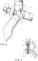
- Fig. 1 shows a schematic three-dimensional representation of a wind turbine 1 according to the prior art.
- the wind turbine 1 comprises a tower 2, on which a tower head 3 is applied, which usually has a generator, not shown. It is further shown a rotor hub 4, are connected to the rotor blades 5 on the blade root 6 with the rotor hub 4. It is also schematically a rotor blade connection 17 indicated and a rotor blade tip 41, which should be used to explain the drawings below.
- Fig. 2 shows a schematic three-dimensional representation of a part of the wind turbine 1 from Fig. 1 of the prior art.
- the rotor hub 4 is connected via screw connections, not shown, which may be provided by flange holes 9 and holes 12, via a flange 11 and a generator shaft 10 with a generator.
- openings 7 and 8 are provided in the rotor hub 4.
- the rotor blades 5 are connected to the blade roots 6 with the rotor hub 4.
- Cross pins 14 and nuts 15 are provided, with corresponding holes 16 and holes are provided in the respective material to allow a connection.
- To tighten the nuts 15 corresponding openings 7 and 8 are provided in the rotor hub 4. By tightening the nuts 15, a bias voltage is generated.
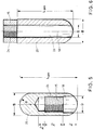
- Fig. 4 shows a schematic sectional view of a preferred rotor blade connection 17.
- a transverse pin 20 is introduced, which has a greater height h than width B.
- the illustrated depth t / 2 corresponds to half the actual depth t of the transverse pin 20, since it is in Fig. 4 is a sectional view along about half through the material of the wall 22 acts.
- the cross pin 20 has a cross section which is elliptical in this embodiment.
- an ellipse for receiving the corresponding forces in the bias due to the screwing of the screw 21 and the blade pin 21 in the thread 24, which is provided in the transverse pin 20 , the optimal shape.
- the bolt variant is provided.
- the transverse pin 20 or transverse pin is a rectangle, preferably with rounded edges in cross-section or an eight or a soft double-T is a preferred form.
- the transverse pins 20 of the FIGS. 4 and 5 have a blind hole 25 with thread.
- a 45 m long blade is the entire length L ges or height h of the cross pin 20 preferably approximately 2.5 x the width B.
- the width B is preferably in the range of 1.5 to 1,7 x the size of the Screw thread, so with a M30 screws 45 mm up to 50 mm.
- the position of the thread is approximately in the middle in the transverse pin 20 or bolt. It is a relatively large bore, despite a corresponding cross-sectional loss of advantage, since the local stresses on tensile load bore edge thereby decrease, which has a positive effect on the life. It should be chosen a high material quality, to get along with a low depth of engagement. It may also be advantageous to provide the tractioned edge of the bore with residual compressive residual stresses.
- transverse pin 20 This can be done for example by shot blasting or preheating or the like. As a result, the life of the transverse pin 20 is increased. It can also be provided by special thread shapes, such as a Sge leopardgewinde the radial forces that want to widen the thread to reduce. It can also be provided to provide the screws or bolts or setscrews with a strain shaft and / or optionally with a fine thread in the transverse pin or transverse pin area.
- standard threads are provided in the region of the assembly screw connection to the nut 42, that is to say in the case of a screw connection in the field under difficult conditions.
- the cross section can be as in Fig. 4 be executed in an elliptical shape, which can contribute to optimal stress in the laminate cross-section.
- the position of the cross pin 20 should preferably be provided as close as possible to the blade root.
- the laminate wall thickness in the wall 22 should be in the range of 2 x the width B to 3 x the width B. x is the operator of multiplication. For better illustration, the blade root end 19 of the blade root is still shown and the longitudinal axis 18 of the expansion bolts 21st
- the preferred embodiment of the transverse pin 20 of the Fig. 5 is such that B lies in the range of 45 mm, the total height L tot in the range of approx. 110 mm, wherein a thread M27 is used and the diameter D of the blind hole in the lower region is approx. 32 mm, h 1 is approx 30 mm and h 2 at about 30 mm. In the range of h 2 , the thread 24 is provided and h 3 is about 15 mm. This results in a laminate thickness of preferably 100 mm. The total depth t is therefore about 100 mm.
- An alternative transverse pin 20 is in Fig. 6 shown. It is a partially oval transverse pin having a through hole 26 and a through hole 26. In this case, it is provided that the diameter D of the bore should be as small as possible in order to achieve a maximum cross-sectional area of B xt - ⁇ / 4 ⁇ D 2 .
- the width B can in the range of the embodiment according to Fig. 5 be.
- the total height L tot is preferably greater than 2.5 x the width B.
- the nut 24 may be connected to the transverse pin 20. It can also be provided interlocking elements to facilitate screwing a screw into the thread 24 of the nut 15 during assembly.
- transverse pin 20 in a schematic sectional view in Fig. 7 shown.
- the through hole 26 is provided at the top with a thread 24. Due to the elongated shape of the transverse pin 20, a higher resistance moment is given in the rotor blade connection, whereby the transverse pin can be made narrower than in the prior art.
- Fig. 8 a schematic plan view of a portion of a preferred blade root 6 is shown.
- the provided in the leaf root Bending or rounding is neglected here in the illustration.
- the rotor hub or the connection flange is in the Fig. 8 not shown. In the prior art, it is such that the number of connection pairs of cross pin and screws, which are all provided in a single row, are at the same distance from the blade flange or the leaf root-side end 10.
- connection pairs are determined by the thread diameter of the axial pin or transverse pin 20, 20 'and the load applied.
- the loads increase, whereby the bending moment in the cross bolt increases, so the cross bolt must be thicker.
- only a few transverse bolts can be arranged on the circumference of the blade root 6, whereby the load acting on the individual cross-bolt increases.
- the invention now provides for providing at least two planes of transverse bolts or at least two rows 33, 34 of transverse bolts with different distances to the blade root on the blade root-side end 19. As a result, the forces can be divided accordingly and the distances of the respective transverse pins 20 and 20 'are reduced, whereby an increased number of transverse pins 20, 20' can be used.
- the transverse pin 20 preferably has a diameter of 60 mm.
- a M30 screw or M30 bolt with 24 mm shank is provided for the first row 33 of the transverse pins 20 which are guided through the hole 12, and longer bolts or screw connections with a 20 mm shank for the second row 34 of transverse pins 20 '. which are guided by the longer holes 12 '.
- the diameter of the blade root or the circle, which is defined by the cross pins, is about 2.11 m.
- the preferred distance of the first row of pins from the blade root end 19 is preferably about 150 mm and the distance of the second row of pins 34 from the blade root end 19 is preferably about 215 mm.
- the laminate thickness is preferably about 100 mm.
- h1 is approx. 150 mm and h2 65 mm as just indicated.
- A1 is approx. 332 mm and A2 166 mm.
- A3 is about 83 mm.
- the laminate stiffness in the longitudinal axis of the sheet is as high as possible, ie as many unidirectional layers as possible in the sheet longitudinal direction, ie at 0 ° to the sheet longitudinal direction.
- the load is best distributed between the two rows 33 and 34 when the shear modulus of the laminate is as high as possible, ie as many as possible +/- 45 ° layers of the laminate are provided.
- a preferred ratio of the phase orientations in the blade root 6 is approximately 55% 0 ° unidirectional plies 14% 90 ° unidirectional plies and 31% +/- 45 ° plies.
- the second row of the cross pin 34 receives, as it is front view of the sheet load, an increased load compared to the first row 33.
- the bolts of the second row are selectively designed softer than that the first row. This happens, for example, by providing different thin shafts of the bolts or screws, which are brought into operative connection with the transverse pins 20 '.
- the circular cross-section transverse pins can also be as already stated above, differently shaped transverse pins may be provided, which in particular have a greater height than width.
- the rows of holes can also be closer together than currently shown in this example. It is for example a pitch of 166 mm and a distance of the hole rich of 65 mm provided. The distance of the rows of holes to the root-side end 19 may still be a little smaller than shown, so that the difference in the bolt length or screw length is reduced.
- Fig. 9 shows a schematic sectional view of another preferred rotor blade connection 17th
- a somewhat shorter transverse pin 20 is used, which is provided on the pin sides 37 and 37 'to the inner surface 35 and the outer surface 36 of the rotor blade or leaf root 6 with cover laminate 27, 27'. This results in a complete encapsulation of the cross pin 20. This increases the strength of the combination of the transverse pin 20 with the blade root 6. It is made so that first the root laminate is made in the thickness that is necessary to support the transverse pin 20 , This laminate is then provided with the holes for the transverse pins 20 and also with the holes for the screws 13. The transverse pins 20 are then mounted. It will then be inside and out around the central laminate so much more laminate inserted to safely transfer the loads from the rotor blade to the central laminate ring.
- a particularly advantageous embodiment of this connection principle or this rotor blade connection is to manufacture the central laminate part in a glass fiber-metal hybrid laminate.
- the leaf half shells may initially be dry and not yet grained (RIM from Resin Infusion Molding). It is then inserted the belt in the form of unidirectional glass fibers or carbon fibers. A half ring is made and attached with prefabricated cross pin connections or pre-connections. This is followed by a vacuum RIM and subsequent gluing of the sheet half shells. In this manufacturing process, a relatively good joining accuracy is necessary.
- RIM Resin Infusion Molding
- An alternative procedure or an alternative method provides that after the provision of the leaf half shells of the belt is inserted, the Rimen, in particular vacuum Rimen takes place, then gluing the fingertschschalen, then providing the corresponding holes for the transverse pins and the Screw connection and then sticking an inner and outer ring, which consist of a total of three or four parts. If the connection is conical, three parts are provided and if the connection is cylindrical four parts are provided.
- Fig. 9 also shows a threaded blind hole 28 which is provided with a thread 24 'in order to easily replace this in case of a defect of the transverse pin 20.
- the laminate in the region of the transverse pin 20 is removed from the inner side 35, a screw screwed into the blind hole 28, the cross pin 20 pulled out, inserted a new transverse pin 20 and the laminate 27 'reapplied again.
- this embodiment can be combined with the aforementioned embodiments,
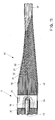
- Fig. 10 shows a schematic sectional view of a rotor blade connection 17 according to the invention. It is essentially a blade root 6 in the transition to the normal Blattschalenlaminat the rotor blade 5 is shown.
- the idea is realized to increase the allowable surface stress by providing metal layers 32.
- the provided transverse pins 20 in the obstruction with an in Fig. 10 not shown screw subject to a very high bias.
- the metal sheets or metal foils that are present in a metal layer 32 are preferably so thin that they can nestle themselves in the form of, for example, a semicircle. Preferably, these have a thickness between 0.2 mm and 0.4 mm.
- the structure that results is a hybrid structure of alternating metal layers 32 and glass fiber reinforced plastic layers 31.
- the thickness of the glass fiber layers in this embodiment is 1.2 mm. With a glass fiber reinforced plastic thickness of 1.2 mm and a thickness of, for example, 0.3 mm steel, the steel content is 20%.
- the additional bolt force decreases in particular under tensile load, since the ratio of the stiffness of the strained parts to the rigidity of the tensile-loaded part is cheaper. This results in a more favorable influence on the stress conditions of the screw connection, whereby the additional load in the transverse pin 20 clearly is reduced.
- the high compressive strength of metal significantly increases the bearing fatigue strength.
- the position by layer reduction in the length of the layers in the axial direction of the longitudinal axis of the rotor blade or the longitudinal axis 18 of the screw, not shown, or the longitudinal axis 18 of the through hole 26 is a very quick and easy production and control of the production allows.
- unidirectional glass fiber mats are also used in the longitudinal axial direction of the rotor blade in order to be able to distribute plastic according to the RIM process in accordance with even.
- the layer-by-layer transition each with shorter layers of glass-fiber reinforced plastic and metal, can be seen particularly well in the transition region 40.
- lower layers 31 are preferably carried out continuously to the outside of the sheet.
- a cover layer 30 or 30 ' is provided.
- Fig. 11 shows a further rotor blade connection according to the invention 17 in a schematic sectional view, in which a kind of hybrid layer of metal layers and glass fiber reinforced plastic layers are provided.
- a kind of hybrid layer of metal layers and glass fiber reinforced plastic layers are provided in contrast to the embodiment according to Fig. 10 .
- the in Fig. 11 illustrated lower area also shown angled in cross-section, which is particularly well visible on the cover layer 30 '.
- the central axis of the blade wall is here substantially with the screw longitudinal axis 18 one above the other.
- a perforated metal layer 32 or a plurality of perforated metal layers 32 can also be used. This leads to a better distribution of the plastic in the blade root 6 and in the transition region 40.
- the depth t can in the embodiments according to Fig. 10 and Fig. 11 at the blade root end of the rotor blade at 50 mm to 100 mm.
- the diameter of the transverse pin 20 may be 45 mm.
- the distance from the blade root end to the center of the transverse pin 20 is about 2.5 x the diameter of the transverse pin 20, that is about 112 mm.
- the transition region 40 also begins to taper at about 112 mm from the center of the transverse pin 20 to taper. These dimensions are preferred for a rotor blade of 40 m to 45 m.
- the taper of the rotor blade in the transition region 40 may extend over a distance of 300 mm to about 1400 mm.
- the thickness of the supporting laminate of the sheet tray at 29 is then about 15 mm to 20 mm.
- the embodiments according to the Figures 10 and 11 can be combined with the aforementioned embodiments of the invention.
Claims (15)
- Pale de rotor (5) ayant une attache de pale de rotor (17) pour une éolienne (1) afin de raccorder la pale de rotor (5) à un dispositif d'assemblage (4), comportant un dispositif d'assemblage (13, 21) et une goupille transversale (20, 20') en liaison active avec le dispositif d'assemblage (13, 21), caractérisée en ce que le matériau (30 à 32) de la pale de rotor (5) comporte, au moins dans la zone de la goupille transversale (20, 20'), une structure constituée de couches de matière plastique renforcées par des fibres (31) et de couches constituées d'un matériau de renfort (32) incluant un métal.
- Pale de rotor (5) selon la revendication 1, dans laquelle, lorsque la pale de rotor (5) est montée sur un moyeu de rotor (4) d'une éolienne (1), une précontrainte est exercée au moins sur le dispositif d'assemblage (13, 21), caractérisée en ce que la zone s'étend jusqu'à la zone dans laquelle une force s'exerce sur le matériau (30 à 32) de la pale de rotor (5) en raison de la précontrainte.
- Pale de rotor (5) selon la revendication 1 ou la revendication 2, caractérisée en ce que la zone s'étend jusqu'à la zone de l'emplanture de pale de rotor (6).
- Pale de rotor (5) selon l'une des revendications 1 à 3, caractérisée en ce que dans une zone de transition (40) destinée à adapter la structure de l'emplanture de pale de rotor (6) à la structure de la pale de rotor (5, 29), une extension au moins partielle d'une couche à l'autre, en particulier constante, des couches (32) constituées du matériau de renfort (32) est prévu jusqu'à la pointe de la pale de rotor (41).
- Pale de rotor (5) selon l'une des revendications 1 à 4, caractérisée en ce que le matériau de renfort (32) est un métal.
- Pale de rotor (5) selon la revendication 5, caractérisée en ce que le métal est présent sous la forme d'un film (32) ou d'un treillis.
- Pale de rotor (5) selon la revendication 6, caractérisée en ce que l'épaisseur du film (32) est comprise entre 0,1 mm et 0,8 mm, en particulier entre 0,15 mm et 0,5 mm, en particulier entre 0,2 mm et 0,3 mm.
- Pale de rotor (5) selon l'une des revendications 1 à 7, caractérisée en ce que l'épaisseur des couches de matière plastique renforcées par des fibres (31) est comprise entre 0,2 mm et 1 mm, en particulier entre 0,4 mm et 0,9 mm, en particulier entre 0,6 mm et 0,7 mm.
- Pale de rotor (5) selon l'une des revendications 1 à 8, caractérisée en ce qu'au moins une partie des couches de matière plastique renforcées par des fibres (31) comporte des fibres orientées de manière unidirectionnelle qui sont alignées dans une direction longitudinale axiale de la pale de rotor (5).
- Pale de rotor (5) selon l'une des revendications 1 à 9, caractérisée en ce que l'axe longitudinal (18) du dispositif d'assemblage (13, 21) est sensiblement aligné avec l'axe central (18) des parois de pale de rotor (5) et se situe en particulier dans un plan commun avec celui-ci.
- Pale de rotor (5) selon l'une des revendications 1 à 10, caractérisée en ce que le dispositif d'assemblage (13, 21) comporte une vis (13, 21), en particulier une vis à tige extensible (21).
- Pale de rotor (5) selon l'une des revendications 1 à 11, caractérisée en ce que plusieurs dispositifs d'assemblage (13, 21) sont prévus, lesquels dispositifs d'assemblage sont chacun en liaison active avec au moins une goupille transversale (20, 20').
- Pale de rotor (5) selon l'une des revendications 1 à 12, caractérisée en ce que la liaison active engendre une précontrainte.
- Rotor (4, 5) d'une éolienne (1) comportant au moins une pale de rotor (5) selon l'une des revendications 1 à 13 et un moyeu de rotor (4).
- Utilisation d'une éolienne (1) ayant une pale de rotor (5) selon l'une des revendications 1 à 14.
Applications Claiming Priority (2)
| Application Number | Priority Date | Filing Date | Title |
|---|---|---|---|
| DE102006022272A DE102006022272C5 (de) | 2006-05-11 | 2006-05-11 | Rotorblattanschluss |
| EP07724417.6A EP2016283B1 (fr) | 2006-05-11 | 2007-04-20 | Pale d'eolienne comprennant un raccord de pale de rotor |
Related Parent Applications (2)
| Application Number | Title | Priority Date | Filing Date |
|---|---|---|---|
| EP07724417.6A Division EP2016283B1 (fr) | 2006-05-11 | 2007-04-20 | Pale d'eolienne comprennant un raccord de pale de rotor |
| EP07724417.6A Division-Into EP2016283B1 (fr) | 2006-05-11 | 2007-04-20 | Pale d'eolienne comprennant un raccord de pale de rotor |
Publications (2)
| Publication Number | Publication Date |
|---|---|
| EP2910773A1 EP2910773A1 (fr) | 2015-08-26 |
| EP2910773B1 true EP2910773B1 (fr) | 2018-02-28 |
Family
ID=38283007
Family Applications (3)
| Application Number | Title | Priority Date | Filing Date |
|---|---|---|---|
| EP07724417.6A Not-in-force EP2016283B1 (fr) | 2006-05-11 | 2007-04-20 | Pale d'eolienne comprennant un raccord de pale de rotor |
| EP12174056.7A Not-in-force EP2505826B1 (fr) | 2006-05-11 | 2007-04-20 | Connexion pour pâle de rotor |
| EP15156312.9A Not-in-force EP2910773B1 (fr) | 2006-05-11 | 2007-04-20 | Connexion pour pale de rotor |
Family Applications Before (2)
| Application Number | Title | Priority Date | Filing Date |
|---|---|---|---|
| EP07724417.6A Not-in-force EP2016283B1 (fr) | 2006-05-11 | 2007-04-20 | Pale d'eolienne comprennant un raccord de pale de rotor |
| EP12174056.7A Not-in-force EP2505826B1 (fr) | 2006-05-11 | 2007-04-20 | Connexion pour pâle de rotor |
Country Status (8)
| Country | Link |
|---|---|
| US (2) | US8133029B2 (fr) |
| EP (3) | EP2016283B1 (fr) |
| CN (1) | CN101443547B (fr) |
| CA (1) | CA2649674C (fr) |
| DE (1) | DE102006022272C5 (fr) |
| DK (3) | DK2910773T3 (fr) |
| ES (3) | ES2605943T3 (fr) |
| WO (1) | WO2007131589A2 (fr) |
Families Citing this family (39)
| Publication number | Priority date | Publication date | Assignee | Title |
|---|---|---|---|---|
| DE102006022272C5 (de) * | 2006-05-11 | 2013-07-25 | Repower Systems Ag | Rotorblattanschluss |
| GB2465167A (en) * | 2008-11-07 | 2010-05-12 | Vestas Wind Sys As | A turbine blade having mounting inserts of different lengths |
| GB0822681D0 (en) * | 2008-12-12 | 2009-01-21 | Aviat Entpr Ltd | Rotor blades |
| GB0900945D0 (en) * | 2009-01-21 | 2009-03-04 | Aquamarine Power Ltd | Composite blade |
| DE102010002268B4 (de) * | 2010-02-24 | 2013-10-17 | Prof. Dr.-Ing., Siegfried Schmalzried | Bearbeitungsstation zur Bearbeitung von Rotorblättern für Windkraftanlagen |
| DE102010017062B4 (de) * | 2010-05-21 | 2019-07-11 | Thyssenkrupp Steel Europe Ag | Rotorblatt einer Windkraftanlage |
| US8025485B2 (en) * | 2010-06-17 | 2011-09-27 | General Electric Company | Wind turbine blade attachment configuration with flattened bolts |
| DE202010013535U1 (de) | 2010-09-24 | 2010-12-02 | Repower Systems Ag | Blattanschluss eines Rotorblatts einer Windenergieanlage |
| EP2511477B1 (fr) * | 2011-04-11 | 2014-06-04 | LM WP Patent Holding A/S | Pale d'éolienne dotée d'une région de transition |
| US20140030094A1 (en) * | 2011-04-11 | 2014-01-30 | Lm Wp Patent Holding A/S | Wind turbine blade having a root region with elongated fastening members provided with metal fibres |
| DE202011100897U1 (de) * | 2011-05-17 | 2011-10-14 | Windnovation Engineering Solutions Gmbh | Befestigung von Rotorblättern auf der Nabe von Windenergieanlagen |
| DE202011101634U1 (de) * | 2011-06-09 | 2011-07-14 | EUROS- Entwicklungsgesellschaft für Windkraftanlagen mbH | Rotorblattverbindung |
| EP2554834B1 (fr) | 2011-08-02 | 2016-07-13 | Alstom Wind, S.L.U. | Rotor pour éolienne |
| EP2592264B1 (fr) | 2011-11-11 | 2014-12-31 | Nordex Energy GmbH | Raccord de pale pour une pale de rotor d'une éolienne |
| DE102011088025A1 (de) * | 2011-12-08 | 2013-06-13 | Wobben Properties Gmbh | Rotorblatt |
| ES2606879T3 (es) * | 2012-02-17 | 2017-03-28 | Adwen Offshore, S.L. | Turbina eólica de accionamiento directo |
| KR101345716B1 (ko) | 2012-09-07 | 2013-12-27 | 삼성중공업 주식회사 | 풍력발전기용 결합 보조 장치 및 이에 의한 결합 방법 |
| EP2920457B1 (fr) * | 2012-11-14 | 2017-01-11 | XEMC Darwind B.V. | Procédé de fabrication d'un élément de pale d'une éolienne |
| ES2475491B1 (es) | 2013-01-10 | 2015-04-17 | Ingeniería Prosix, S.L. | Pala de turbina eólica |
| DE102014205195A1 (de) * | 2014-03-20 | 2015-09-24 | Wobben Properties Gmbh | Windenergieanlagen-Rotorblatt, Windenergieanlagen-Rotorblattanschluss und Windenergieanlage |
| DE102014005452B4 (de) | 2014-04-07 | 2015-12-24 | Windnovation Engineering Solutions Gmbh | Blattanschluss für Rotorblätter |
| US9293281B2 (en) * | 2014-04-29 | 2016-03-22 | Abb Technology Ag | Tank mounting structure for dead tank circuit breaker |
| EP2952739A1 (fr) * | 2014-06-05 | 2015-12-09 | Siemens Aktiengesellschaft | Chemise de protection pour une emplanture d'aube de rotor de turbine éolienne, pied de pale, pale de rotor de turbine éolienne et éolienne |
| US9777704B2 (en) * | 2014-11-03 | 2017-10-03 | General Electric Company | Rotor blade assembly for a wind turbine having variable-length blade bolts |
| FR3030345B1 (fr) * | 2014-12-17 | 2017-09-08 | Dcns | Procede de fabrication d'un element en materiau composite presentant un orifice et/ou un insert |
| US20160377052A1 (en) * | 2015-06-29 | 2016-12-29 | General Electric Company | Blade root section for a modular rotor blade and method of manufacturing same |
| CN105673350B (zh) * | 2016-01-19 | 2018-08-07 | 洛阳双瑞风电叶片有限公司 | 一种风电叶片根部金属法兰盘的安装方法 |
| DE102016110551A1 (de) * | 2016-06-08 | 2017-12-14 | Wobben Properties Gmbh | Rotor für eine Windenergieanlage, Rotorblatt für eine Windenergieanlage, Hülse und Verfahren zur Montage eines Rotors |
| DE102017003061B4 (de) | 2017-03-30 | 2022-11-24 | Albany Engineered Composites, Inc. | Anschlusselement |
| GB2569294A (en) * | 2017-12-08 | 2019-06-19 | Vestas Wind Sys As | Method of repairing a joint connecting a wind turbine rotor blade to a rotor hub |
| ES2940570T3 (es) * | 2020-01-15 | 2023-05-09 | Siemens Gamesa Renewable Energy As | Porción de raíz de una pala de turbina eólica, pala de turbina eólica, conjunto de raíz y turbina eólica |
| US11885294B2 (en) * | 2020-01-17 | 2024-01-30 | Wobben Properties Gmbh | Wind turbine, wind turbine rotor blade, and blade bearing for a wind turbine |
| CN113137345A (zh) * | 2021-04-30 | 2021-07-20 | 上海电气风电集团股份有限公司 | 风力发电机的叶片及风轮 |
| EP4092261A1 (fr) * | 2021-05-21 | 2022-11-23 | Nordex Energy SE & Co. KG | Élément de pale de rotor d'éolienne avec des ensembles de connexion |
| EP4116574A1 (fr) * | 2021-07-05 | 2023-01-11 | Siemens Gamesa Renewable Energy A/S | Ensemble base d'une pale pour éolienne, pale d'éolienne et éolienne |
| EP4116573A1 (fr) * | 2021-07-05 | 2023-01-11 | Siemens Gamesa Renewable Energy A/S | Ensemble base d'une pale pour éolienne, pale d'éolienne et éolienne |
| EP4119790A1 (fr) * | 2021-07-12 | 2023-01-18 | General Electric Renovables España S.L. | Ensemble pale de turbine éolienne et procédés |
| WO2023227180A1 (fr) * | 2022-05-24 | 2023-11-30 | Vestas Wind Systems A/S | Pale d'éolienne |
| WO2023227181A1 (fr) * | 2022-05-24 | 2023-11-30 | Vestas Wind Systems A/S | Pale d'éolienne |
Family Cites Families (34)
| Publication number | Priority date | Publication date | Assignee | Title |
|---|---|---|---|---|
| DE408174C (de) | 1920-10-30 | 1925-01-09 | Henry Leitner | Fluegelbefestigung fuer aus ineinander gelagerten Lamellen bestehende Metallhohlpropeller |
| FR565621A (fr) | 1923-04-28 | 1924-01-31 | Moulinet récepteur | |
| US2863513A (en) * | 1955-12-12 | 1958-12-09 | Bell Aircraft Corp | Helicopter rotor blade |
| US3161239A (en) * | 1963-01-18 | 1964-12-15 | Andersen F S | Impeller constructions |
| GB1262704A (en) * | 1968-08-10 | 1972-02-02 | Messerschmitt Boelkow Blohm | Helicopter rotor blade |
| US3835610A (en) * | 1972-06-28 | 1974-09-17 | Arkana Ltd | Joint for joining structural members |
| DE2525791C3 (de) * | 1975-06-10 | 1978-08-31 | Reinhard-Heinrich 4830 Guetersloh Floetotto | Anordnung zum Verbinden zweier aufeinander stoßender platten- oder stangenförmiger Elemente |
| DE2658876C3 (de) | 1976-12-24 | 1983-11-10 | Hütter, Ulrich, Prof. Dr.-Ing., 7312 Kirchheim | Schalenkörper, beispielsweise Trag- oder Rotorflügel, in Composite-Bauweise |
| US4148594A (en) * | 1977-06-10 | 1979-04-10 | Ssp Agricultural Equipment, Inc. | Fan blade for wind machines |
| DE2832098C2 (de) * | 1978-07-21 | 1982-06-03 | Messerschmitt-Bölkow-Blohm GmbH, 8000 München | Anordnung zur Zug- bzw. Längskrafteinleitung bei einem Bauteil in Sandwichbauweise |
| US4236873A (en) | 1978-09-20 | 1980-12-02 | United Technologies Corporation | Wind turbine blade retention device |
| US4367864A (en) * | 1980-02-22 | 1983-01-11 | Eldeen Gene H | Newel post assembly |
| DE3103710C2 (de) * | 1981-02-04 | 1983-03-24 | Messerschmitt-Bölkow-Blohm GmbH, 8000 München | "Rotor in Schalenbauweise" |
| DE3109566C2 (de) * | 1981-03-13 | 1983-04-07 | Messerschmitt-Bölkow-Blohm GmbH, 8000 München | Rotorblatt für Windenergiemaschinen und Spannvorrichtung zu seiner Montage |
| DE3113079C2 (de) | 1981-04-01 | 1985-11-21 | Messerschmitt-Bölkow-Blohm GmbH, 8000 München | Aerodynamischer Groß-Flügel und Verfahren zu dessen Herstellung |
| CA1244913A (fr) * | 1985-09-16 | 1988-11-15 | Michael S. Hrycyshyn | Systeme detecteur de liquide pour appareils faisant appel audit liquide, et sondes allant de pair avec le systeme |
| US4976587A (en) * | 1988-07-20 | 1990-12-11 | Dwr Wind Technologies Inc. | Composite wind turbine rotor blade and method for making same |
| US5664899A (en) * | 1991-07-22 | 1997-09-09 | Eustis; Robert H. | Furniture joint |
| FR2683007B1 (fr) | 1991-10-28 | 1994-01-07 | Aerospatiale Ste Nationale Indle | Procede pour assembler une premiere piece en materiau sandwich et une seconde piece metallique, et assemblage obtenu. |
| DE9201280U1 (fr) * | 1992-02-03 | 1992-05-21 | Sperl, Guido, Dipl.-Ing.(Fh), 8203 Niederaudorf, De | |
| BR9300312A (pt) * | 1993-02-02 | 1993-07-27 | Alpina Equipamentos Ind Ltda | Aperfeicoamento em pas de plasticos reforcados com fibras |
| DE29618525U1 (de) * | 1996-10-24 | 1997-05-15 | Aerodyn Energiesysteme Gmbh | Blattflansch für Rotorblätter von Windkraftanlagen |
| DE19733372C1 (de) * | 1997-08-01 | 1999-01-07 | Aloys Wobben | Rotorblatt und Rotor einer Windenergieanlage |
| DE19826086A1 (de) * | 1998-06-12 | 1999-12-16 | Mekra Lang Gmbh & Co Kg | Verfahren zum Herstellen eines Rotorblatts für Windkraftanlagen und Rotorblatt für Windkraftanlagen |
| DE19903550C1 (de) * | 1999-01-29 | 2000-05-25 | Muehlbauer Luftfahrttechn Gmbh | Blattwurzel für Propeller- und Rotorblätter |
| SE514094C2 (sv) * | 1999-05-19 | 2001-01-08 | Kamewa Ab | Fartygspropeller med löstagbart fastsatta blad |
| US6213719B1 (en) * | 1999-07-28 | 2001-04-10 | United Technologies Corporation | Bar wedge preload apparatus for a propeller blade |
| NL1013807C2 (nl) * | 1999-12-09 | 2001-07-05 | Aerpac Holding B V | Windturbinerotor, alsmede naaf en extender daarvoor. |
| FR2821129B1 (fr) * | 2001-02-22 | 2003-05-16 | Eads Airbus Sa | Dispositif d'assemblage d'un panneau et d'une structure, apte a transmettre des efforts importants |
| DE10214340C1 (de) | 2002-03-28 | 2003-11-27 | Aerodyn Eng Gmbh | Blattanschluß für die Rotorblätter einer Windenergieanlage und Verfahren zu dessen Herstellung |
| DE10324166B4 (de) * | 2003-05-28 | 2005-05-04 | Aloys Wobben | Rotorblattanschluss |
| EP1486415A1 (fr) * | 2003-06-12 | 2004-12-15 | SSP Technology A/S | Pale de turbine éolienne et procédé de fabrication de la base d'une pale d'éolienne |
| DE10336998A1 (de) * | 2003-08-12 | 2005-03-10 | Noi Immobilien Und Vermoegensv | Windenergieanlage |
| DE102006022272C5 (de) * | 2006-05-11 | 2013-07-25 | Repower Systems Ag | Rotorblattanschluss |
-
2006
- 2006-05-11 DE DE102006022272A patent/DE102006022272C5/de not_active Expired - Fee Related
-
2007
- 2007-04-20 EP EP07724417.6A patent/EP2016283B1/fr not_active Not-in-force
- 2007-04-20 EP EP12174056.7A patent/EP2505826B1/fr not_active Not-in-force
- 2007-04-20 CN CN2007800169997A patent/CN101443547B/zh not_active Expired - Fee Related
- 2007-04-20 DK DK15156312.9T patent/DK2910773T3/en active
- 2007-04-20 EP EP15156312.9A patent/EP2910773B1/fr not_active Not-in-force
- 2007-04-20 ES ES07724417.6T patent/ES2605943T3/es active Active
- 2007-04-20 US US12/299,055 patent/US8133029B2/en not_active Expired - Fee Related
- 2007-04-20 CA CA2649674A patent/CA2649674C/fr not_active Expired - Fee Related
- 2007-04-20 ES ES15156312.9T patent/ES2670329T3/es active Active
- 2007-04-20 DK DK12174056.7T patent/DK2505826T3/en active
- 2007-04-20 ES ES12174056.7T patent/ES2565630T3/es active Active
- 2007-04-20 WO PCT/EP2007/003481 patent/WO2007131589A2/fr active Application Filing
- 2007-04-20 DK DK07724417.6T patent/DK2016283T3/da active
-
2012
- 2012-01-30 US US13/361,055 patent/US8408875B2/en not_active Expired - Fee Related
Non-Patent Citations (1)
| Title |
|---|
| None * |
Also Published As
| Publication number | Publication date |
|---|---|
| US8133029B2 (en) | 2012-03-13 |
| CN101443547A (zh) | 2009-05-27 |
| ES2565630T3 (es) | 2016-04-06 |
| EP2505826B1 (fr) | 2016-01-13 |
| CA2649674A1 (fr) | 2007-11-22 |
| CA2649674C (fr) | 2013-01-15 |
| ES2605943T3 (es) | 2017-03-17 |
| ES2670329T3 (es) | 2018-05-30 |
| WO2007131589A2 (fr) | 2007-11-22 |
| EP2910773A1 (fr) | 2015-08-26 |
| EP2016283A2 (fr) | 2009-01-21 |
| US20120148404A1 (en) | 2012-06-14 |
| DE102006022272C5 (de) | 2013-07-25 |
| DK2910773T3 (en) | 2018-06-06 |
| US20090263250A1 (en) | 2009-10-22 |
| EP2505826A3 (fr) | 2015-02-18 |
| CN101443547B (zh) | 2012-08-15 |
| DE102006022272A1 (de) | 2007-11-15 |
| DK2505826T3 (en) | 2016-04-18 |
| DE102006022272B4 (de) | 2008-06-12 |
| EP2505826A2 (fr) | 2012-10-03 |
| EP2016283B1 (fr) | 2016-08-31 |
| US8408875B2 (en) | 2013-04-02 |
| DK2016283T3 (da) | 2017-01-02 |
| WO2007131589A3 (fr) | 2008-04-10 |
Similar Documents
| Publication | Publication Date | Title |
|---|---|---|
| EP2910773B1 (fr) | Connexion pour pale de rotor | |
| DE102006022279B4 (de) | Rotorblatt für eine Windenergieanlage | |
| DE102007020339B4 (de) | Rotorblatt für eine Windturbine | |
| DE102006014742B4 (de) | Rotorblatt für Windenergieanlagen | |
| DE102013101233B4 (de) | Wurzelendanordnungskonfiguration für ein Windkraftanlagenrotorblatt | |
| EP2035694B1 (fr) | Moyeu de rotor d'une éolienne | |
| DE102011088025A1 (de) | Rotorblatt | |
| DE102011056176A1 (de) | Verbindungsmuffe für eine Rotorblattanordnung einer Windkraftanlage | |
| EP1636490B1 (fr) | Raccord de pale de rotor | |
| WO2006039953A1 (fr) | Pale de rotor d'une centrale eolienne | |
| DE102012108125A1 (de) | Rotorblatt für eine Windkraftanlage und Verfahren zum Herstellen desselben | |
| DE102011050966A1 (de) | Blattlbefestigungskonfiguration für eine Windkraftanlage mit abgeflachten Bolzen | |
| DE102014221966B4 (de) | Verfahren zum Herstellen eines Rotorblatts einer Windenergieanlage | |
| WO2017211929A1 (fr) | Rotor pour éolienne, pale de rotor pour éolienne, manchon et procédé de montage d'un rotor | |
| EP3120017A1 (fr) | Pale de rotor d'éolienne équipée d'un raccord de pale de rotor et procédé de fabrication | |
| EP3486476B1 (fr) | Entretoise pour une pale de rotor d'une éolienne et procédé de fabrication d'une entretoise | |
| EP3855014A1 (fr) | Pale de rotor divisée d'une éolienne ainsi que segment de pale de rotor | |
| EP3559417B1 (fr) | Procédé de fabrication d'une pale de rotor d'éolienne et pale de rotor d'éolienne | |
| EP3564523B1 (fr) | Raccordement à bride pour une pale de rotor d'éolienne, base de raidissement pour un raccordement à bride, insert de bride, pale de rotor d'éolienne, éolienne ainsi que procédé de fabrication d'un raccordement à bride | |
| EP4155530B1 (fr) | Pale de rotor pour éolienne | |
| DE102010039778A1 (de) | Rotorblatt für Windenergieanlagen | |
| EP3775532B1 (fr) | Pale de rotor d'éolienne et éolienne | |
| EP3376024A1 (fr) | Pale de rotor d'éolienne divisible comprenant une liaison par boulonnage | |
| DE102017106875B4 (de) | Windkraftanlage und Verfahren zu dessen Montage | |
| EP3887670A1 (fr) | Procédé d'introduction d'une courroie de pale de rotor dans une coque de pale de rotor, moule de courroie, pale de rotor ainsi qu'éolienne |
Legal Events
| Date | Code | Title | Description |
|---|---|---|---|
| PUAI | Public reference made under article 153(3) epc to a published international application that has entered the european phase |
Free format text: ORIGINAL CODE: 0009012 |
|
| 17P | Request for examination filed |
Effective date: 20150224 |
|
| AC | Divisional application: reference to earlier application |
Ref document number: 2016283 Country of ref document: EP Kind code of ref document: P |
|
| AK | Designated contracting states |
Kind code of ref document: A1 Designated state(s): AT BE BG CH CY CZ DE DK EE ES FI FR GB GR HU IE IS IT LI LT LU LV MC MT NL PL PT RO SE SI SK TR |
|
| RAP1 | Party data changed (applicant data changed or rights of an application transferred) |
Owner name: SENVION GMBH |
|
| 17Q | First examination report despatched |
Effective date: 20161205 |
|
| GRAP | Despatch of communication of intention to grant a patent |
Free format text: ORIGINAL CODE: EPIDOSNIGR1 |
|
| INTG | Intention to grant announced |
Effective date: 20171114 |
|
| GRAS | Grant fee paid |
Free format text: ORIGINAL CODE: EPIDOSNIGR3 |
|
| GRAA | (expected) grant |
Free format text: ORIGINAL CODE: 0009210 |
|
| AC | Divisional application: reference to earlier application |
Ref document number: 2016283 Country of ref document: EP Kind code of ref document: P |
|
| AK | Designated contracting states |
Kind code of ref document: B1 Designated state(s): AT BE BG CH CY CZ DE DK EE ES FI FR GB GR HU IE IS IT LI LT LU LV MC MT NL PL PT RO SE SI SK TR |
|
| REG | Reference to a national code |
Ref country code: GB Ref legal event code: FG4D Free format text: NOT ENGLISH Ref country code: CH Ref legal event code: EP |
|
| REG | Reference to a national code |
Ref country code: AT Ref legal event code: REF Ref document number: 974446 Country of ref document: AT Kind code of ref document: T Effective date: 20180315 |
|
| REG | Reference to a national code |
Ref country code: IE Ref legal event code: FG4D Free format text: LANGUAGE OF EP DOCUMENT: GERMAN |
|
| REG | Reference to a national code |
Ref country code: DE Ref legal event code: R096 Ref document number: 502007016088 Country of ref document: DE |
|
| REG | Reference to a national code |
Ref country code: FR Ref legal event code: PLFP Year of fee payment: 12 |
|
| REG | Reference to a national code |
Ref country code: ES Ref legal event code: FG2A Ref document number: 2670329 Country of ref document: ES Kind code of ref document: T3 Effective date: 20180530 |
|
| REG | Reference to a national code |
Ref country code: DK Ref legal event code: T3 Effective date: 20180530 |
|
| REG | Reference to a national code |
Ref country code: NL Ref legal event code: MP Effective date: 20180228 |
|
| REG | Reference to a national code |
Ref country code: LT Ref legal event code: MG4D |
|
| PG25 | Lapsed in a contracting state [announced via postgrant information from national office to epo] |
Ref country code: LT Free format text: LAPSE BECAUSE OF FAILURE TO SUBMIT A TRANSLATION OF THE DESCRIPTION OR TO PAY THE FEE WITHIN THE PRESCRIBED TIME-LIMIT Effective date: 20180228 Ref country code: CY Free format text: LAPSE BECAUSE OF FAILURE TO SUBMIT A TRANSLATION OF THE DESCRIPTION OR TO PAY THE FEE WITHIN THE PRESCRIBED TIME-LIMIT Effective date: 20180228 Ref country code: NL Free format text: LAPSE BECAUSE OF FAILURE TO SUBMIT A TRANSLATION OF THE DESCRIPTION OR TO PAY THE FEE WITHIN THE PRESCRIBED TIME-LIMIT Effective date: 20180228 Ref country code: FI Free format text: LAPSE BECAUSE OF FAILURE TO SUBMIT A TRANSLATION OF THE DESCRIPTION OR TO PAY THE FEE WITHIN THE PRESCRIBED TIME-LIMIT Effective date: 20180228 |
|
| PG25 | Lapsed in a contracting state [announced via postgrant information from national office to epo] |
Ref country code: GR Free format text: LAPSE BECAUSE OF FAILURE TO SUBMIT A TRANSLATION OF THE DESCRIPTION OR TO PAY THE FEE WITHIN THE PRESCRIBED TIME-LIMIT Effective date: 20180529 Ref country code: BG Free format text: LAPSE BECAUSE OF FAILURE TO SUBMIT A TRANSLATION OF THE DESCRIPTION OR TO PAY THE FEE WITHIN THE PRESCRIBED TIME-LIMIT Effective date: 20180528 Ref country code: LV Free format text: LAPSE BECAUSE OF FAILURE TO SUBMIT A TRANSLATION OF THE DESCRIPTION OR TO PAY THE FEE WITHIN THE PRESCRIBED TIME-LIMIT Effective date: 20180228 Ref country code: SE Free format text: LAPSE BECAUSE OF FAILURE TO SUBMIT A TRANSLATION OF THE DESCRIPTION OR TO PAY THE FEE WITHIN THE PRESCRIBED TIME-LIMIT Effective date: 20180228 |
|
| PG25 | Lapsed in a contracting state [announced via postgrant information from national office to epo] |
Ref country code: MT Free format text: LAPSE BECAUSE OF FAILURE TO SUBMIT A TRANSLATION OF THE DESCRIPTION OR TO PAY THE FEE WITHIN THE PRESCRIBED TIME-LIMIT Effective date: 20180228 |
|
| PG25 | Lapsed in a contracting state [announced via postgrant information from national office to epo] |
Ref country code: PL Free format text: LAPSE BECAUSE OF FAILURE TO SUBMIT A TRANSLATION OF THE DESCRIPTION OR TO PAY THE FEE WITHIN THE PRESCRIBED TIME-LIMIT Effective date: 20180228 Ref country code: RO Free format text: LAPSE BECAUSE OF FAILURE TO SUBMIT A TRANSLATION OF THE DESCRIPTION OR TO PAY THE FEE WITHIN THE PRESCRIBED TIME-LIMIT Effective date: 20180228 Ref country code: IT Free format text: LAPSE BECAUSE OF FAILURE TO SUBMIT A TRANSLATION OF THE DESCRIPTION OR TO PAY THE FEE WITHIN THE PRESCRIBED TIME-LIMIT Effective date: 20180228 Ref country code: EE Free format text: LAPSE BECAUSE OF FAILURE TO SUBMIT A TRANSLATION OF THE DESCRIPTION OR TO PAY THE FEE WITHIN THE PRESCRIBED TIME-LIMIT Effective date: 20180228 |
|
| REG | Reference to a national code |
Ref country code: DE Ref legal event code: R097 Ref document number: 502007016088 Country of ref document: DE |
|
| PG25 | Lapsed in a contracting state [announced via postgrant information from national office to epo] |
Ref country code: CZ Free format text: LAPSE BECAUSE OF FAILURE TO SUBMIT A TRANSLATION OF THE DESCRIPTION OR TO PAY THE FEE WITHIN THE PRESCRIBED TIME-LIMIT Effective date: 20180228 Ref country code: SK Free format text: LAPSE BECAUSE OF FAILURE TO SUBMIT A TRANSLATION OF THE DESCRIPTION OR TO PAY THE FEE WITHIN THE PRESCRIBED TIME-LIMIT Effective date: 20180228 Ref country code: MC Free format text: LAPSE BECAUSE OF FAILURE TO SUBMIT A TRANSLATION OF THE DESCRIPTION OR TO PAY THE FEE WITHIN THE PRESCRIBED TIME-LIMIT Effective date: 20180228 |
|
| REG | Reference to a national code |
Ref country code: CH Ref legal event code: PL |
|
| REG | Reference to a national code |
Ref country code: BE Ref legal event code: MM Effective date: 20180430 |
|
| PLBE | No opposition filed within time limit |
Free format text: ORIGINAL CODE: 0009261 |
|
| STAA | Information on the status of an ep patent application or granted ep patent |
Free format text: STATUS: NO OPPOSITION FILED WITHIN TIME LIMIT |
|
| REG | Reference to a national code |
Ref country code: IE Ref legal event code: MM4A |
|
| PG25 | Lapsed in a contracting state [announced via postgrant information from national office to epo] |
Ref country code: LU Free format text: LAPSE BECAUSE OF NON-PAYMENT OF DUE FEES Effective date: 20180420 |
|
| 26N | No opposition filed |
Effective date: 20181129 |
|
| PG25 | Lapsed in a contracting state [announced via postgrant information from national office to epo] |
Ref country code: BE Free format text: LAPSE BECAUSE OF NON-PAYMENT OF DUE FEES Effective date: 20180430 Ref country code: CH Free format text: LAPSE BECAUSE OF NON-PAYMENT OF DUE FEES Effective date: 20180430 Ref country code: SI Free format text: LAPSE BECAUSE OF FAILURE TO SUBMIT A TRANSLATION OF THE DESCRIPTION OR TO PAY THE FEE WITHIN THE PRESCRIBED TIME-LIMIT Effective date: 20180228 Ref country code: LI Free format text: LAPSE BECAUSE OF NON-PAYMENT OF DUE FEES Effective date: 20180430 |
|
| PG25 | Lapsed in a contracting state [announced via postgrant information from national office to epo] |
Ref country code: IE Free format text: LAPSE BECAUSE OF NON-PAYMENT OF DUE FEES Effective date: 20180420 |
|
| REG | Reference to a national code |
Ref country code: AT Ref legal event code: MM01 Ref document number: 974446 Country of ref document: AT Kind code of ref document: T Effective date: 20180420 |
|
| PG25 | Lapsed in a contracting state [announced via postgrant information from national office to epo] |
Ref country code: AT Free format text: LAPSE BECAUSE OF NON-PAYMENT OF DUE FEES Effective date: 20180420 |
|
| PG25 | Lapsed in a contracting state [announced via postgrant information from national office to epo] |
Ref country code: TR Free format text: LAPSE BECAUSE OF FAILURE TO SUBMIT A TRANSLATION OF THE DESCRIPTION OR TO PAY THE FEE WITHIN THE PRESCRIBED TIME-LIMIT Effective date: 20180228 |
|
| PG25 | Lapsed in a contracting state [announced via postgrant information from national office to epo] |
Ref country code: PT Free format text: LAPSE BECAUSE OF FAILURE TO SUBMIT A TRANSLATION OF THE DESCRIPTION OR TO PAY THE FEE WITHIN THE PRESCRIBED TIME-LIMIT Effective date: 20180228 |
|
| PG25 | Lapsed in a contracting state [announced via postgrant information from national office to epo] |
Ref country code: HU Free format text: LAPSE BECAUSE OF FAILURE TO SUBMIT A TRANSLATION OF THE DESCRIPTION OR TO PAY THE FEE WITHIN THE PRESCRIBED TIME-LIMIT; INVALID AB INITIO Effective date: 20070420 |
|
| PG25 | Lapsed in a contracting state [announced via postgrant information from national office to epo] |
Ref country code: IS Free format text: LAPSE BECAUSE OF FAILURE TO SUBMIT A TRANSLATION OF THE DESCRIPTION OR TO PAY THE FEE WITHIN THE PRESCRIBED TIME-LIMIT Effective date: 20180628 |
|
| PGFP | Annual fee paid to national office [announced via postgrant information from national office to epo] |
Ref country code: DE Payment date: 20200423 Year of fee payment: 14 Ref country code: FR Payment date: 20200421 Year of fee payment: 14 Ref country code: ES Payment date: 20200516 Year of fee payment: 14 Ref country code: DK Payment date: 20200423 Year of fee payment: 14 |
|
| PGFP | Annual fee paid to national office [announced via postgrant information from national office to epo] |
Ref country code: GB Payment date: 20200423 Year of fee payment: 14 |
|
| REG | Reference to a national code |
Ref country code: DE Ref legal event code: R119 Ref document number: 502007016088 Country of ref document: DE |
|
| REG | Reference to a national code |
Ref country code: DK Ref legal event code: EBP Effective date: 20210430 |
|
| GBPC | Gb: european patent ceased through non-payment of renewal fee |
Effective date: 20210420 |
|
| PG25 | Lapsed in a contracting state [announced via postgrant information from national office to epo] |
Ref country code: DE Free format text: LAPSE BECAUSE OF NON-PAYMENT OF DUE FEES Effective date: 20211103 Ref country code: FR Free format text: LAPSE BECAUSE OF NON-PAYMENT OF DUE FEES Effective date: 20210430 Ref country code: GB Free format text: LAPSE BECAUSE OF NON-PAYMENT OF DUE FEES Effective date: 20210420 |
|
| PG25 | Lapsed in a contracting state [announced via postgrant information from national office to epo] |
Ref country code: DK Free format text: LAPSE BECAUSE OF NON-PAYMENT OF DUE FEES Effective date: 20210430 |
|
| REG | Reference to a national code |
Ref country code: ES Ref legal event code: FD2A Effective date: 20220704 |
|
| PG25 | Lapsed in a contracting state [announced via postgrant information from national office to epo] |
Ref country code: ES Free format text: LAPSE BECAUSE OF NON-PAYMENT OF DUE FEES Effective date: 20210421 |