EP2909103B1 - Verpackung für arzneimittel für klinische studien oder gewerbliche anwendung - Google Patents
Verpackung für arzneimittel für klinische studien oder gewerbliche anwendung Download PDFInfo
- Publication number
- EP2909103B1 EP2909103B1 EP13783190.5A EP13783190A EP2909103B1 EP 2909103 B1 EP2909103 B1 EP 2909103B1 EP 13783190 A EP13783190 A EP 13783190A EP 2909103 B1 EP2909103 B1 EP 2909103B1
- Authority
- EP
- European Patent Office
- Prior art keywords
- inner portion
- vial
- shape
- aperture
- present
- Prior art date
- Legal status (The legal status is an assumption and is not a legal conclusion. Google has not performed a legal analysis and makes no representation as to the accuracy of the status listed.)
- Active
Links
Images


Classifications
-
- B—PERFORMING OPERATIONS; TRANSPORTING
- B65—CONVEYING; PACKING; STORING; HANDLING THIN OR FILAMENTARY MATERIAL
- B65D—CONTAINERS FOR STORAGE OR TRANSPORT OF ARTICLES OR MATERIALS, e.g. BAGS, BARRELS, BOTTLES, BOXES, CANS, CARTONS, CRATES, DRUMS, JARS, TANKS, HOPPERS, FORWARDING CONTAINERS; ACCESSORIES, CLOSURES, OR FITTINGS THEREFOR; PACKAGING ELEMENTS; PACKAGES
- B65D85/00—Containers, packaging elements or packages, specially adapted for particular articles or materials
- B65D85/30—Containers, packaging elements or packages, specially adapted for particular articles or materials for articles particularly sensitive to damage by shock or pressure
- B65D85/42—Containers, packaging elements or packages, specially adapted for particular articles or materials for articles particularly sensitive to damage by shock or pressure for ampoules; for lamp bulbs; for electronic valves or tubes
-
- B—PERFORMING OPERATIONS; TRANSPORTING
- B65—CONVEYING; PACKING; STORING; HANDLING THIN OR FILAMENTARY MATERIAL
- B65B—MACHINES, APPARATUS OR DEVICES FOR, OR METHODS OF, PACKAGING ARTICLES OR MATERIALS; UNPACKING
- B65B5/00—Packaging individual articles in containers or receptacles, e.g. bags, sacks, boxes, cartons, cans, jars
- B65B5/02—Machines characterised by incorporation of means for making the containers or receptacles
- B65B5/024—Machines characterised by incorporation of means for making the containers or receptacles for making containers from preformed blanks
-
- B—PERFORMING OPERATIONS; TRANSPORTING
- B65—CONVEYING; PACKING; STORING; HANDLING THIN OR FILAMENTARY MATERIAL
- B65D—CONTAINERS FOR STORAGE OR TRANSPORT OF ARTICLES OR MATERIALS, e.g. BAGS, BARRELS, BOTTLES, BOXES, CANS, CARTONS, CRATES, DRUMS, JARS, TANKS, HOPPERS, FORWARDING CONTAINERS; ACCESSORIES, CLOSURES, OR FITTINGS THEREFOR; PACKAGING ELEMENTS; PACKAGES
- B65D77/00—Packages formed by enclosing articles or materials in preformed containers, e.g. boxes, cartons, sacks or bags
- B65D77/003—Articles enclosed in rigid or semi-rigid containers, the whole being wrapped
-
- B—PERFORMING OPERATIONS; TRANSPORTING
- B65—CONVEYING; PACKING; STORING; HANDLING THIN OR FILAMENTARY MATERIAL
- B65D—CONTAINERS FOR STORAGE OR TRANSPORT OF ARTICLES OR MATERIALS, e.g. BAGS, BARRELS, BOTTLES, BOXES, CANS, CARTONS, CRATES, DRUMS, JARS, TANKS, HOPPERS, FORWARDING CONTAINERS; ACCESSORIES, CLOSURES, OR FITTINGS THEREFOR; PACKAGING ELEMENTS; PACKAGES
- B65D77/00—Packages formed by enclosing articles or materials in preformed containers, e.g. boxes, cartons, sacks or bags
- B65D77/02—Wrapped articles enclosed in rigid or semi-rigid containers
-
- B—PERFORMING OPERATIONS; TRANSPORTING
- B65—CONVEYING; PACKING; STORING; HANDLING THIN OR FILAMENTARY MATERIAL
- B65D—CONTAINERS FOR STORAGE OR TRANSPORT OF ARTICLES OR MATERIALS, e.g. BAGS, BARRELS, BOTTLES, BOXES, CANS, CARTONS, CRATES, DRUMS, JARS, TANKS, HOPPERS, FORWARDING CONTAINERS; ACCESSORIES, CLOSURES, OR FITTINGS THEREFOR; PACKAGING ELEMENTS; PACKAGES
- B65D77/00—Packages formed by enclosing articles or materials in preformed containers, e.g. boxes, cartons, sacks or bags
- B65D77/04—Articles or materials enclosed in two or more containers disposed one within another
- B65D77/0413—Articles or materials enclosed in two or more containers disposed one within another the inner and outer containers being rigid or semi-rigid and the outer container being of polygonal cross-section formed by folding or erecting one or more blanks, e.g. carton
- B65D77/042—Articles or materials enclosed in two or more containers disposed one within another the inner and outer containers being rigid or semi-rigid and the outer container being of polygonal cross-section formed by folding or erecting one or more blanks, e.g. carton the inner container being of polygonal cross-section formed by folding or erecting one or more blanks, e.g. carton
-
- B—PERFORMING OPERATIONS; TRANSPORTING
- B65—CONVEYING; PACKING; STORING; HANDLING THIN OR FILAMENTARY MATERIAL
- B65D—CONTAINERS FOR STORAGE OR TRANSPORT OF ARTICLES OR MATERIALS, e.g. BAGS, BARRELS, BOTTLES, BOXES, CANS, CARTONS, CRATES, DRUMS, JARS, TANKS, HOPPERS, FORWARDING CONTAINERS; ACCESSORIES, CLOSURES, OR FITTINGS THEREFOR; PACKAGING ELEMENTS; PACKAGES
- B65D77/00—Packages formed by enclosing articles or materials in preformed containers, e.g. boxes, cartons, sacks or bags
- B65D77/04—Articles or materials enclosed in two or more containers disposed one within another
- B65D77/0413—Articles or materials enclosed in two or more containers disposed one within another the inner and outer containers being rigid or semi-rigid and the outer container being of polygonal cross-section formed by folding or erecting one or more blanks, e.g. carton
- B65D77/0426—Articles or materials enclosed in two or more containers disposed one within another the inner and outer containers being rigid or semi-rigid and the outer container being of polygonal cross-section formed by folding or erecting one or more blanks, e.g. carton the inner container being a bottle, canister or like hollow container
-
- B—PERFORMING OPERATIONS; TRANSPORTING
- B65—CONVEYING; PACKING; STORING; HANDLING THIN OR FILAMENTARY MATERIAL
- B65D—CONTAINERS FOR STORAGE OR TRANSPORT OF ARTICLES OR MATERIALS, e.g. BAGS, BARRELS, BOTTLES, BOXES, CANS, CARTONS, CRATES, DRUMS, JARS, TANKS, HOPPERS, FORWARDING CONTAINERS; ACCESSORIES, CLOSURES, OR FITTINGS THEREFOR; PACKAGING ELEMENTS; PACKAGES
- B65D81/00—Containers, packaging elements, or packages, for contents presenting particular transport or storage problems, or adapted to be used for non-packaging purposes after removal of contents
- B65D81/02—Containers, packaging elements, or packages, for contents presenting particular transport or storage problems, or adapted to be used for non-packaging purposes after removal of contents specially adapted to protect contents from mechanical damage
- B65D81/05—Containers, packaging elements, or packages, for contents presenting particular transport or storage problems, or adapted to be used for non-packaging purposes after removal of contents specially adapted to protect contents from mechanical damage maintaining contents at spaced relation from package walls, or from other contents
- B65D81/127—Containers, packaging elements, or packages, for contents presenting particular transport or storage problems, or adapted to be used for non-packaging purposes after removal of contents specially adapted to protect contents from mechanical damage maintaining contents at spaced relation from package walls, or from other contents using rigid or semi-rigid sheets of shock-absorbing material
- B65D81/133—Containers, packaging elements, or packages, for contents presenting particular transport or storage problems, or adapted to be used for non-packaging purposes after removal of contents specially adapted to protect contents from mechanical damage maintaining contents at spaced relation from package walls, or from other contents using rigid or semi-rigid sheets of shock-absorbing material of a shape specially adapted to accommodate contents, e.g. trays
-
- B—PERFORMING OPERATIONS; TRANSPORTING
- B65—CONVEYING; PACKING; STORING; HANDLING THIN OR FILAMENTARY MATERIAL
- B65D—CONTAINERS FOR STORAGE OR TRANSPORT OF ARTICLES OR MATERIALS, e.g. BAGS, BARRELS, BOTTLES, BOXES, CANS, CARTONS, CRATES, DRUMS, JARS, TANKS, HOPPERS, FORWARDING CONTAINERS; ACCESSORIES, CLOSURES, OR FITTINGS THEREFOR; PACKAGING ELEMENTS; PACKAGES
- B65D2201/00—Means or constructions for testing or controlling the contents
Definitions
- Embodiments of the present invention relate generally to packaging for clinical trials.
- embodiments of the present invention are directed to customized packaging for vials (injectable compounds) designed to facilitate labeling and distribution of clinical or commercial supplies.
- Packaging and more specifically, packaging of vials, is well known in the art.
- prior art packagings include a removable dosage unit, which may be removed from an outer pack to prepare the medication.
- a removable dosage unit which may be removed from an outer pack to prepare the medication.
- the purpose of these prior art packagings is to allow for rapid visual inspection and to be consumer friendly.
- These prior art packages do not allow for reduced labeling to support clinical trials.
- FR 1 407 142 discloses a two-piece package for bottles which has the features of the preamble of appended claim 1.
- Embodiments of the present invention provide a package that can allow for reduced labeling to support clinical trials or commercial use.
- a package for receiving a vial includes an inner portion constructed out of a first piece of material folded into a first shape configured to receive the vial therein; an outer portion constructed out of a second piece of material folded into a second shape configured to removably receive the first shape of the inner portion; and an identifying mark or label disposed on the inner portion and being viewable when the first shape of the inner portion is disposed within the second shape of the outer portion.
- the inner portion includes a top portion that defines s first aperture configured to receive the vial, , a bottom portion, and first and second side portions and a top flap securable to at least one of the top portion and the first and second side portions so as to retain the vial within the first aperture, the top flap having defined therein a second aperture configured to permit access to contents of the vial without removing the vial from the inner portion.
- the second aperture may have a diameter selected to permit a top of the vial to protrude therethrough.
- Some embodiments further include a cap protector configured to be disposed over the inner portion and including an indented portion sized to accommodate and protect a top of the vial.
- a side aperture is defined within the side portion of the inner portion, the vial being viewable through the side aperture.
- Some embodiments further include one or more tape panels that seal the inner portion in the first shape so as to evidence tampering with the inner portion.
- the outer portion further includes side portions that include cutouts to ease in removal of the inner portion from the outer portion.
- an inside of the first shape of the inner portion includes a vial support configured to stabilize the vial within the inner portion.
- At least one of the inner and outer portions includes a tab, slot, or flap configured to interlock the first shape of the inner portion with the second shape of the outer portion so as to permit partial removal of the inner portion from the outer portion and to inhibit complete removal of the inner portion from the outer portion.
- the inner and outer portions respectively are formed using a single piece of material.
- a kit for preparing a package for receiving a vial includes an inner portion that is folded flat and is foldable into a first shape configured to receive the vial therein; and an outer portion that is folded flat and is foldable into a second shape configured to removably receive the first shape of the inner portion.
- the inner portion has an area for receiving an identifying mark or label that is viewable when the inner and outer portions respectively are folded into the first and second shapes and the first shape is disposed within the second shape so as to form the package.
- the first shape into which the inner portion is foldable includes a top portion that defines a first aperture configured to receive the vial, , a bottom portion, and first and second side portions and a top flap securable to at least one of the top portion and the first and second side portions so as to retain the vial within the first aperture, the top flap having defined therein a second aperture configured to permit access to contents of the vial without removing the vial from the inner portion.
- the second aperture may have a diameter selected to permit a top of the vial to protrude therethrough.
- Some embodiments further include a cap protector configured to be disposed over the inner portion and including an indented portion sized to accommodate and protect a top of the vial.
- a side aperture is defined within the side portion of the inner portion, the vial being viewable through the side aperture.
- Some embodiments further include one or more tape panels for use in sealing the inner portion in the first shape so as to evidence tampering with the inner portion.
- the outer portion further includes side portions that include cutouts to ease in removal of the inner portion from the outer portion.
- an inside of the first shape of the inner portion includes a vial support configured to stabilize the vial within the inner portion.
- At least one of the inner and outer portions includes a tab, slot, or flap configured to interlock the first shape of the inner portion with the second shape of the outer portion so as to permit partial removal of the inner portion from the outer portion and to inhibit complete removal of the inner portion from the outer portion.
- the inner and outer portions respectively are formed using a single piece of material.
- a method of packaging a vial includes constructing an inner portion by folding a first piece of material into a first shape configured to receive the vial therein; disposing the vial within the first shape of the inner portion; constructing an outer portion by folding a second piece of material into a second shape configured to removably receive the first shape of the inner portion; and inserting the inner portion into the outer portion.
- the inner portion has an area for receiving an identifying mark or label that is viewable when the inner and outer portions respectively are folded into the first and second shapes and the first shape is disposed within the second shape so as to form a package.
- the inner portion includes a top portion that defines a first aperture configured to receive the vial, a bottom portion, and first and second side portions, and a top flap, the method including securing the top flap to at least one of the top portion and the first and second side portions so as to retain the vial within the first aperture, the top flap having defined therein a second aperture permitting access to contents of the vial without removing the vial from the inner portion.
- the second aperture has a diameter selected to permit a top of the vial to protrude therethrough.
- Some embodiments further include disposing a cap protector over the inner portion, the cap protector including an indented portion sized to accommodate and protect a top of the vial.
- a side aperture is defined within the side portion of the inner portion, the vial being viewable through the side aperture.
- Some embodiments further include sealing the inner portion in the first shape using one or more tape panels that evidence tampering with the inner portion.
- the outer portion further includes side portions that include cutouts to ease in removal of the inner portion from the outer portion.
- an inside of the first shape of the inner portion includes a vial support that stabilizes the vial within the inner portion.
- Some embodiments further include interlocking the first shape of the inner portion with the second shape of the outer portion with a tab, slot, or flap on at least one of the inner and outer portions so as to permit partial removal of the inner portion from the outer portion and to inhibit complete removal of the inner portion from the outer portion.
- the inner and outer portions respectively are formed using a single piece of material.
- inventions include packaging including an inner portion that includes a top portion, a bottom portion, and a side portion.
- the inner portion further includes a top flap, where the top flap includes a small top aperture, and a large top aperture capable of receiving a vial.
- the packaging further includes an outer portion.
- the inner portion is constructed out of at least one piece of material, where the one piece of material is folded into a desired shape capable of receiving a vial therein.
- the inner portion engages with the outer portion such that an identifying mark or label is capable of being viewed on the inner portion, or on a medium included in the inner portion through an aperture on the inner portion, while the inner portion and outer portion are so engaged.
- kits for a package including at least three separate components, including: an inner portion; an outer portion; and a cap protector.
- the inner portion and the outer portion are folded flat, and the inner portion is capable of being refolded into a shape that is capable of receiving a vial therein.
- the outer portion is capable of being refolded into a shape that is capable of receiving the inner portion therein.
- Assembly of the package includes engaging the three components of the kit by placing the cap protector on the inner portion, and placing the inner portion within the outer portion, where the cap protector is disposed between a portion of the inner portion and a portion of the outer portion.
- inventions of the present invention further include a method of packaging a vial including folding a first component into an inner portion, where the inner portion includes a top portion, a bottom portion, and a side portion.
- the inner portion further includes a top flap, where the top flap includes a small top aperture, and a large top aperture capable of receiving a vial.
- the method of packaging a vial further includes folding a second component into an outer portion, inserting a vial into the large top aperture of the inner portion, sealing the vial within the inner portion by closing the top flap, inserting a cap protector on the inner portion, and inserting the inner portion into the outer portion.
- Yet another embodiment of the present invention is directed to a package including an inner portion, where the inner portion includes a vial holding portion.
- the vial holding portion includes a plurality of sides and a hollow space capable of including at least a portion of a vial therein, where at least a portion of a top of the vial is accessible when the vial is disposed in the vial holding portion.
- the inner portion further includes a cooperating portion capable of slidably engaging with an outer portion, the cooperating portion including a base, a rear, and sides.
- the sides of the cooperating portion include flaps.
- the package further includes an outer portion with a front surface, a top surface, a bottom surface, and two side surfaces, where a cavity is formed within the outer portion.
- a cutout is formed on the side surfaces of the outer portion, which also includes an engagement portion capable of engaging the flaps.
- the inner portion can be slidingly engaged with the outer portion by being slid into the cavity of the outer portion.
- the flaps of the inner portion engage with the engagement portion of the outer portion thereby holding the inner portion within the cavity of the outer portion.
- An area of the sides of the cooperating portion of the inner portion are exposed through the cutout formed on the side surfaces of the outer portion when the inner portion is disposed within the cavity of the outer portion.
- a user may disengage the inner portion from the outer portion by grabbing the area of the sides of the cooperating portion of the inner portion that is exposed and pulling the inner portion away from the cavity of the outer portion.
- kits for a package including at least two separate components, where the two separate components include an inner portion and an outer portion.
- the inner portion and the outer portion are folded flat, and the inner portion is capable of being refolded into a shape that is capable of forming a vial holding portion for receiving a vial therein and a cooperating portion for slidably engaging with the outer portion.
- the outer portion is capable of being refolded into a shape that is capable of receiving the inner portion in a cavity included in the outer portion. Assembly of the package includes engaging the two components of the kit by sliding the inner portion within the cavity of the outer portion.
- Yet another embodiment of the present invention is directed to a method of packaging a vial including folding a first component into an inner portion, where the inner portion includes a vial holding portion with a plurality of sides and a hollow space capable of receiving at least a portion of a vial therein. At least a portion of a top of the vial is accessible when the vial is disposed in the vial holding portion.
- the inner portion further includes a cooperating portion capable of slidably engaging with an outer portion, the cooperating portion including a base, a rear, and sides, where the sides include flaps.
- the method of packaging a vial further includes inserting the inner portion into the outer portion.
- Packagings of the prior art include vials that are labeled and packaged into an outer carton.
- the vials are considered the primary container and would need to be unpacked at the point of distribution to be further labeled with any ancillary Annex 13 label that may be required.
- the prior art design is not desirable for clinical trials.
- many packagings of the prior art do not include features that allow a person to see the contents of the vials contained therein when the vials are still located in the packagings.
- Embodiments of the present invention are directed to a carton (packaging) that may hold a vial within.
- An embodiment of the present invention allows a materials supply chain to label only a single level of packaging.
- Embodiments of the present invention are designed in a manner that will allow practitioners to prepare and administer the contents of the vial without removing the immediate container from the outer packaging.
- Another embodiment of the present invention includes a packaging that holds a vial (or similar), where the vial cannot be removed without intentionally destroying the internal components of the packaging (for example, the components shown in Figures 4 and 27 ).
- Embodiments of the present invention allow for a clinical trial pooled supply for vial based/injectable compounds. Embodiments of the present invention also dramatically reduce packaging and labeling costs. Embodiments of the present invention can be used for clinical trials in countries/regions that must comply with Annex 13 requirements. Additionally, embodiments of the present invention are capable of being used in countries that have other requirements (in addition to, or in replace of, Annex 13 requirements).
- Embodiments of the present invention include sealing individual vials into a primary container.
- sealing vials into the container allows a materials supply chain to apply an Annex 13 compliant label only to the container.
- Embodiments of the present invention are described throughout this application as being used to hold vials.
- Vials as used throughout this application include any type of container, and are not limited to the traditional definition of vials.
- the contents of the vials included within the packages of embodiments of the present invention may be anything that a person skilled in the art would desire to be present in a container.
- the vials may also be empty.
- the vials that may be included within the packages of embodiments of the present invention may include caps and/or rubber stoppers or the like.
- the caps may include flip tops, twist tops, plug tops, or the like.
- the rubber stoppers, caps, or the like may be made of a material that is meant to be punctured by a needle for containing an injectable medicament or the like.
- embodiments of the present invention may be used to package other items instead of, or in addition to, vials.
- the protective flip-cap and rubber stopper are fully accessible for preparation, dosing, and administration of the contents.
- An embodiment of the present invention includes a die cut top flap. It will be apparent to one skilled in the art that the top flap may include an aperture that is made through other methods other than die cutting as well.
- the die cut top flap ensures the vial cannot be removed after the top is folded over the top of the vial (e.g., the neck of the vial).
- Embodiments of the present invention may also include tape panels.
- the tape panels include an aggressive tamper evident tape/adhesive that acts to effectively seal the primary container in a closed position.
- the only way to remove the vial is to destroy the package.
- the carton has only one side which needs to be sealed, which may be the top side of the carton (unlike most prior art cartons, which are sealed both at the top and on the bottom).
- apertures are included in certain embodiments of the present invention.
- the apertures are present to facilitate preparation for dosing by allowing a viewing window for the practitioner to inspect the contents of the vial before dosing.
- the apertures may have additional purposes as well, which would be apparent to a person of ordinary skill.
- Embodiments of the present invention may include an outer cover that provides protection from light and any other elements during storage and shipment.
- An embodiment of the present invention includes a carton that has been developed for the purpose of reducing the labeling required for parenteral dosage forms.
- the package of embodiments of the present invention may be similar to a carton. That is, embodiments of the present invention may be constructed out of similar materials that are used for constructing the cartons of the prior art. Therefore, carton and package may be used synonymously throughout this application when referring to embodiments of the present invention.
- the packages of embodiments of the present invention may also be constructed out of different materials, including, but not limited to, paper or wood products, plastic, metal, glass, fiberboard, composite materials, and the like.
- materials other than the materials described herein, may be utilized to construct the packages of embodiments of the present invention, and embodiments of the present invention are not limited to the materials described herein or shown in the figures.
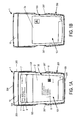
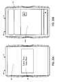
- Figure 1A is a front view of a package 1 constructed according to an illustrative embodiment of the present invention, which includes a pack-out design for injectable, vial based compounds.
- the package 1 shown in Figure 1A includes an inner portion 100 having a vial disposed therein (vial not visible in Figure 1A ), and an outer portion 200.
- the inner portion 100 may be fully inserted within the outer portion 200; as described in greater detail below with reference to Figures 10 and 11 , the inner portion may be fully or partially disengaged from the outer portion 200, which may occur through a sliding motion or the like.
- Embodiments of the present invention also include packages in which the inner portion 100 and the outer portion 200 are engaged through means other than a sliding motion, for example, including, but not limited to, the outer portion 200 wrapping around the inner portion 100.
- the outer portion 200 includes a back portion 202 (not visible in Figure 1A ), side portions 203 optionally having cutouts 207 defined therein, a top portion 204, and a bottom portion 205.
- the inner portion 100 includes a front portion 101, a back portion 102 (not visible in Figure 1A ), a top portion 104, a bottom portion 105, and side portions 103.
- an optional cap protector may be arranged over the top of a vial disposed within the inner portion 100 (vial not visible in Figure 1A ).
- the outer portion 200 acts as an outer sleeve for the inner portion 100 and optional cap protector 10 to be received within.
- a label 2 may be affixed to the front portion 101 of the inner portion 100 of the package 1, preferably which is viewable regardless of the relative spatial arrangement of inner portion 100 and outer portion 200, e.g., may be seen even before the inner portion 100 is removed (separated/slid out) from the outer portion 200.
- the label 2 may include any information that a person skilled in the art would contemplate being present on a label.
- the label may include identifying marks such as Protocol identification 4, lot identification 5, medication identification 6, subject identification 7, dates 8, barcodes 9 (e.g., QR codes), warnings, designs, symbols, pictures, or anything that one skilled in the art may desire to be present on such a package 1.
- the label 2 may be flat or planar, as illustrated in Figure 1A , or alternatively may be a booklet label, which may include one or more leaflets that include study information and/or regulatory information.
- the booklet label may be prominently visible and accessible at all times during shipment and storage.
- Figure 1B depicts a generic booklet label 2a affixed to the front portion 101 of the inner portion 100 of the package 1, which is viewable regardless of the relative spatial arrangement of inner portion 100 and outer portion 200, e.g., may be seen even before the inner portion 100 is removed (separated/slid out) from the outer portion 200.
- a flat label such as label 2 illustrated in Figure 1A may be applied to a generic booklet label 2a such as illustrated in Figure 1B .
- the booklet label or the information therein may be affixed within inner portion 100 (primary container), e.g., may be affixed to the back side of front portion 101 of the inner portion 100, so that the label or information may be seen only when the inner portion 100 is partially or fully removed from the outer portion 200.
- the package 1 may be any color or variety of colors
- the label 2 may be any color or variety of colors.
- an embodiment of the present invention may not include a label on the front portion 101 of the inner portion 100.
- the side portions 203 of the outer portion 200 may include cutouts 207 to ease in removing the inner portion 100 from the outer portion.
- the package 1 further may include a cap protector 10, which is a thick protective portion disposed between the top portion 104 of the inner portion 100 and the top portion 204 of the outer portion.
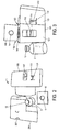
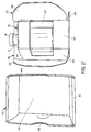
- FIG 2 is a perspective view of a vial 3 and of the components of the package 1 in an unassembled state, according to an embodiment of the present invention.
- the package 1 may include many apertures that may serve a variety of distinctive functions.
- the cap protector 10 may include a thickness that accommodates an indented portion 11.
- the indented portion 11 may be sized to fit a vial top 12 within in order to protect said vial top 12.
- package 1 is designed so that it can be shipped to a vendor or distributor as three flat components (the inner portion 100, the outer portion 200, and the cap protector 10), which may then be assembled to form the package 1 such as illustrated in Figure 1A .
- such components also may include specific training and support materials so that a packaging vendor or distributor can utilize the three flat components and form the package 1.
- Figure 3 depicts the inner portion 100 of the package 1 in a semi-assembled state.
- the vial 3 is placed into the inner portion 100 through the top portion 104.
- the top portion 104 of the inner portion 100 includes a large top aperture 106 and a top flap 108 with a small top aperture 107.
- the large top aperture 106 is sized such that the vial 3 can be inserted into the inner portion 100 through the large top aperture 106.
- the top flap 108 then may be lowered over the vial and sealed into place, e.g., using glue, a tape-panel, pressure-sensitive adhesive, or the like, as described in greater detail below with reference to Figure 6 .
- the small top aperture 107 is sized such that the vial top 12 protrudes through the small top aperture 107 when the top flap 108 is lowered over the vial; optionally, cap protector 10 then may be disposed over vial top 12 such that indented portion 11 engages with vial top 12, such that vial 3 can thus optionally be further protected by the cap protector 10, in addition to protection provided by inner portion 100.
- the inside of the inner portion 100 may include vial supports 110 to help stabilize the vial when it is disposed inside the inner portion 100.
- the outside of the inner portion 100 may also include additional apertures.
- the outside of the inner portion 100 may include a vial label viewing aperture 111 and a side tab aperture 112.
- the outside of the inner portion 100 in an embodiment of the present invention may also include a side tab 113. Side tab aperture 112 and side tab 113 may be used to lock inner portion 100 to outer portion 200.
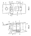
- Figures 6 and 7 show the inner portion 100 of the package 1 fully assembled and closed.
- the top flap 108 overhangs approximately 6,35 mm ( 0.25 inches ) , and folds over a portion of the inner portion 100 (primary container), which may be the front portion 101, back portion 102, or side portion 103.
- the top flap 108 may be secured by glue, a tape-panel, a pressure sensitive adhesive strip that may be exposed when the liner is removed by a packager, or other suitable method of securement.
- apertures may be added to the inner and outer portions, and the number of apertures present is not limited to the number shown in the figures. For example, there may be additional apertures relative to those shown in Figure 6 . These additional apertures may increase the amount of incoming light in order to facilitate preparation of the compound for further preparation and administration.
- Figure 8 depicts the cap protector 10, which may serve as a protector for vial top 12 as well as the top flap 108.
- the cap protector 10 may be utilized as a spacer to ensure a snug fit of the inner portion 100 within the outer portion 200.
- the cap protector 10 protects the vial top 12, which may include a vial flip-cap.
- Figure 9 shows the cap protector 10 engaged with the top portion 104 of the inner portion 100 of the package 1 in an embodiment of the present invention.
- the inner portion 100 slides into the outer portion 200 (outer sleeve).
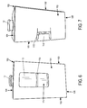
- An embodiment of the present invention may include a locking feature on the outer portion 200 to prevent the inner portion 100 from inadvertently falling out.
- the locking feature is located on the inner portion 100 of the package 1.
- the locking feature may include, but is not limited to, an adhesive, a flap, a latch, a notch, a punch, or the like.
- the inner and outer portions include features that lock to one another so as to inhibit full removal of the inner portion 100 from the outer portion 200 after the inner portion 100 is inserted into the outer portion 200.
- Figures 12-14 depict an inner portion 100 that include additional security features, according to an embodiment of the present invention.
- an inner portion 100 of an embodiment of the present invention that includes tape panels 114.
- the tape panels 114 may include an aggressive tamper evident tape/adhesive that acts to effectively seal the inner portion 100 in a closed position, as shown in Figure 12-14 .
- the only way to remove the vial is to destroy the inner portion 100.
- Embodiments of the present invention may be for drug companies' products that are contained in vials for commercial use, or for use in global clinical studies including, but not limited to, pooled supplies.
- Embodiments of the present invention allow a materials supply chain or similar to have supplies permanently sealed into a secondary package so that companies do not have to label both levels of packaging (i.e., vials and cartons and/or both primary and secondary packages) with trial- and country-specific labeling. In doing so, embodiments of the present invention will reduce the cost of packaging and labeling.
- Embodiments of the present invention also may facilitate the packaging of pooled supplies by ensuring that all labeling is easily accessible for labeling at the point of distribution while maintaining global regulatory compliance, including, but not limited to, Annex 13 compliance (for investigational medicinal products). Additionally, embodiments of the present invention may ensure that there is empty space surrounding the vial, which can reduce the risk of breakage without requiring a separate cell divider, foam liner, or the like.
- Embodiments of the present invention may be packaged and labeled at a vendor, e.g., a packaging or distribution vendor, with appropriate labeling with the exception of study specific Annex 13 information, which prohibits pooling by making the labeling protocol specific (Protocol/Study Number, European Union Drug Regulating Authorities Clinical Trials Number and sponsor information).
- the generically labeled kits that may be included in the packaging of embodiments of the present invention may be kept in inventory as pooled supplies until they are requested for a specific study.
- a Just In Time (JIT) label may be printed at the point of distribution, and may include the Annex 13 information. This label may be applied to embodiments of the present invention just before shipping to a clinical trial site.
- JIT Just In Time
- a packaging or distribution vendor will only need to apply one label.
- Traditional packaging of the prior art would require that a packaging or distribution vendor generates two labels, open each kit, apply a label to the immediate container (vial), repack the vial in the carton, seal the carton, and apply a label to the carton.
- vials may be sealed into the packaging of embodiments of the present invention and a single label may be applied to a portion of the package.
- Embodiments of the present invention will allow a materials supply chain to have supplies permanently sealed into a secondary package so that they do not have to label both levels of packaging (vials and cartons). Thus, embodiments of the present invention will reduce the cost of packaging and labeling.
- Traditional packaging would require that the vendor apply a label to the immediate container (vial), place a liner in the carton (if needed), pack the vial in the carton, seal the carton, and apply a label to the carton.
- the finished goods may be stored at the point of distribution labeled with a generic booklet label (without any protocol/study specific information in the case of a clinical trial, or without any patient-specific information in the case of a commercial product).
- the Protocol Number and European Union Drug Regulating Authorities Clinical Trials Number, or any other patient-specific information may be printed on an ancillary label which may be affixed to the booklet cover at the point of distribution just before shipment to the clinical or commercial site.
- the top of the vial when the package is opened, the top of the vial is fully accessible for preparation, dosing, and administration of the contents.
- the inner portion When an embodiment of the present invention is assembled, the inner portion is held within the outer portion to form a carton.
- the carton can release the inner portion from the outer portion through a user squeezing side tabs and sliding the inner portion out from engagement with the outer portion.
- multiple windows may be included in an embodiment of the present invention.
- the windows are present to facilitate preparation for dosing by allowing a viewing area for the practitioner to inspect the contents of the vial before dosing.
- the windows may have additional purposes as well, which would be apparent to a person of ordinary skill.
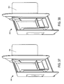
- Figures 15-19 respectively illustrate the front, top, bottom, first side, and second side, views of a package design for injectable, vial based compounds according to a preferred embodiment of the present invention
- Figures 20A-20B respectively illustrate rear views of such a package design having either a flat label or a booklet label.
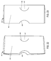
- the package 21 shown in Figures 15-20B includes an inner portion 300 and an outer portion 400, although only outer portion 400 is readily visible in Figures 15, 16 , and 17 .
- Figures 18, 19 , and 20A when the inner portion 300 is engaged with the outer portion 400 such that cavity 401 defined within outer portion 400 receives the inner portion, only the rear 301 and a small area of the cooperating portion sides 302 of the inner portion 300 are visible.
- the rear 301 of the inner portion 300 is visible because of the cavity 401 in the rear of the outer portion 400.
- the outer portion 400 includes a front surface 402, side surfaces 403, a top surface 404, and a bottom surface 405 that collectively define cavity 401.
- the cooperating portion sides 302 of the inner portion 300 are visible because of cutouts 408 included on the side surfaces 403 of the outer portion 400.
- the side surfaces 403 of the outer portion 400 also include substantially semicircular shaped slits 406, which create substantially semicircular flaps 407 that engage with the inner portion 300 as explained in more detail below.
- the outer portion 400 acts as an outer sleeve for the inner portion 300 to be received within.
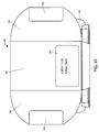
- the bottom surface 405 of the outer portion 400 includes a label 22 in a preferred embodiment of the present invention.
- the label 22 may include any information that a person skilled in the art would contemplate being present on a label.
- the label may include identifying marks such as Protocol identification, lot identification, medication identification, subject identification, dates, barcodes, warnings, designs, symbols, pictures, manufacturer information, supplier information, physician information, or anything that one skilled in the art would desire to be present on such a package 21.
- the label 22 may be flat or planar, or alternatively may include a booklet label, which may comprise study information and/or regulatory information, such as described above with reference to Figure 1A .
- ancillary label text may be included on the label 22 shown in Figure 17
- the main label 399 or 399a of a preferred embodiment of the present invention is affixed to the inner portion 300, shown, for example, in Figure 20A or 20B respectively (i.e., the rear 301 of the inner portion 300).
- the main clinical label is applied to the inner portion 300. Applying the label to the exterior face (the rear 301 of the inner portion 300) when the inner portion 300 is engaged to the outer portion 400 will allow the pharmacist to see the label when the supplies are on the shelf, e.g., as illustrated in Figures 20A or 20B .
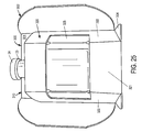
- Figure 26 shows another label 305 disposed on the bottom surface 306 of the inner portion 300.
- This label 305 may include ancillary label text in an embodiment of the present invention.
- the package 21 may be any color or variety of colors
- the label 22 may be any color or variety of colors.
- an embodiment of the present invention may not include a label.
- the inner portion 300 in a preferred embodiment of the present invention holds a vial 23.
- the inner portion 300 includes a vial holding portion 320 and a cooperating portion 310 designed to engage with the outer portion 400.
- the cooperating portion 310 includes the rear 301 and cooperating portion sides 302 of the inner portion 300.
- the cooperating portion 310 allows the inner portion 300 to engage with the outer portion 400 in an embodiment of the present invention.
- the sides 302 are made from the same piece as the rear 301 and are folded inward to create a box shape that can be slid into the cavity 401 of the outer portion 400.
- the entire inner portion 300 is a single component that can be folded and adhered to form the shape shown in the figures.
- the cooperating portion sides 302 include substantially rectangular flaps 303, perhaps best seen in Figure 29 , that are folded down and adhered to the rear portion of the cooperating portion sides 302 in order to cooperate with the substantially semicircular shaped slits 406 formed on the outer portion 400, perhaps best seen in Figures 22 and 23 , when the inner portion 300 is slid into the cavity 401 of the outer portion 400.
- the substantially rectangular flaps 303 may be adhered to the cooperating portion sides 302 by glue, tape, or the like.
- the substantially rectangular flaps 303 are adhered to the cooperating portion sides 302 by a foam glue composite 330 that enables the flaps 303 to project slightly from the cooperating portion sides 302.
- Figure 34-38 illustrate various views of the inner portion 300 in partially assembled states, so as to further illustrate relationships between the various components of the inner portion.
- the base 304 of the cooperating portion 310 also acts as a base for the vial holding portion 320.
- the bottom surface 306 of the base 304 optionally includes a label 305 in an embodiment of the present invention, as perhaps best seen in Figure 26 .
- the label 305 may include the same information as the label 22 on the outer portion 400, or it may include different information.
- the vial holding portion 320 is part of the single component that also makes up the cooperating portion 310 in an embodiment of the present invention.
- a portion extending from the base 304 is folded numerous times to form the shape of the vial holding portion 320 shown in the figures.
- the vial holding portion 320 includes a front 321, sides 322, a top 323, and a vial support 324 that rests on the base 304.
- the vial holding portion 320 further includes a viewing window 325 that may be integrally coupled with the single component that creates the inner portion 300.
- the viewing window 325 may be constructed out of a clear or translucent material so that the contents of the vial 23 (or an optional label on the vial 23) are visible.
- the viewing window 325 may also simply be formed from cutouts in the front 321 and/or sides 322 of the vial holding portion 320.
- the sides 322 of the vial holding portion 320 may be secured onto extensions 326 of the rear, top, and/or bottom portion in order to form a substantially rectangular box shape, which may be accomplished through the use of an adhesive, tape, or the like.
- the top 323 of the vial holding portion 320 includes a top aperture 327 such that the vial top 24 protrudes therethrough.
- the extensions 326 may include, or may be replaced by, a receiving flap to secure closure of the vial holding portion sides 322 in an embodiment of the present invention.
- the vial top 24 is exposed from the vial holding portion 320 of the inner portion 300 such that a user may utilize the contents of the vial 23 while keeping the vial inside of the inner portion 300.
- removal of the vial 23 will cause the package 21, and more specifically the inner portion 300, to be destroyed. In this manner the package 21 is tamper evident.
- vial holding portion 320 may include one or more tape-panels such as described above with reference to Figures 12-14 .
- the substantially rectangular flaps 303 travel past the substantially semicircular shaped slits 406, and the ends 328 of the flaps 303 engage the slits 406 thereby holding the inner portion 300 inside of the outer portion 400.
- the slits 406 and flaps 407 are part of reusable locking system that works with the flaps 303 of the cooperating portion sides 302 to secure the inner portion 300 to the outer portion 400 in an embodiment of the present invention.
- a user to remove the inner portion 300 from the outer portion 400, a user simultaneously presses the substantially semicircular flaps 407 on the outer portion 400, which then presses the substantially rectangular flaps 303 toward the cooperating portion sides 302 of the inner portion 300 and out of engagement with the substantially semicircular shaped slits 406. A user may then slide the inner portion 300 out from the outer portion 400. In an embodiment of the present invention, a user may not remove the inner portion 300 from the outer portion 400 without pressing the flaps 407. In another embodiment of the present invention, simply pulling the exposed portion of the cooperating portion sides 302 of the inner portion 300 with ample force will remove the inner portion 300 from the outer portion 400.
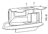
- FIGS 39-41 depict an inner portion 300 constructed in accordance with yet another embodiment of the present invention.
- the inner portion 300 shown in various states of partial assembly in these figures, includes vial holding portion sides 322 that have tabs 331 that fit into slots 332 on the rear of the vial holding portion 320 in order to create the shape of the vial holding portion 320.
- the sides 322 of the vial holding portion 320 in this embodiment are not secured onto extensions in order to form a substantially rectangular box shape, but are instead secured via the tabs 331 being inserted into slots 332.
- the tabs 331 may be part of a dagger locking mechanism, where the tabs 331 are dagger locking tabs and the slots 332 are designed to accept the dagger locking tabs.
- the embodiment of the present invention shown in Figures 39-41 optionally includes a metallic-appearing laminated finish, although one skilled in the art will recognize that the appearance and finish of the packagings described herein is not limited by what is shown in the figures.
- the embodiment of the present invention shown in Figures 39-41 optionally includes a label 305 located on the rear 301 of the inner portion 300.
- a label may be affixed to many portions of embodiments of the present invention and the label location is not limited to the locations shown/described herein.
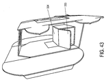
- Figures 42-44 depict a partially assembled inner portion 300 constructed in accordance with another embodiment of the present invention that is similar to the embodiment shown in Figures 39-41 , but also includes additional support structures on the vial support 324 in the form of vertical support flaps 333.
- the vertical support flaps 333 are located on both sides of the vial support 324 to enhance the strength of the vial support 324.
- the vertical support flaps 333 are in the form of vertical fold-down flaps that provide added strength/support when engaged and locked into place when the inner portion 300 of the package 21 is erected/assembled and the vial holding portion sides 322 are assembled using the tabs 331 and slots 332 and/or the extensions 326 or the like.
- any suitable embodiment of the present invention may include vertical support flaps 333 to assist in strengthening the vial support 324, and the vertical support flaps 333 are not limited to the embodiment shown in Figures 42-44 .
- An embodiment of the present invention is designed so that it can be shipped to a vendor as two substantially flat components (the inner portion 300 and the outer portion 400), which may then be assembled to form the package 21.
- Embodiments of the present invention may include specific training and support materials so that a packaging vendor can utilize the two flat components and form the package 21.
- Figures 34-41 depict the inner portion 300 of the package 21 in a semi-assembled state.
- the vial 23 is placed into the vial holding portion 320 of the inner portion 300 through openings in the side 322 of the vial holding portion 320 (before the sides 322 of the vial holding portion 320 are secured in place forming a substantially rectangular box shape).
- Figure 21 depicts the inner portion 300 removed from the outer portion 400.
- the outer portion 400 is made from one solitary piece that is folded over itself for enhanced strength.
- the inner portion 300 may be similarly constructed.
- the inner portion 300 slides into the outer portion 400.
- An embodiment of the present invention may include a locking feature on the outer portion 400 to prevent the inner portion 300 from inadvertently falling out.
- the locking feature may be the flaps 303, 407 and slits 406 explained herein, or any other means known to a person of ordinary skill in the art, such as an adhesive, a flap, a latch, a notch, tabs, a punch, or the like.
- Embodiments of the present invention may include tape panels 329 as a means for adhering to the desired shape of the package 21.
- the tape panels 329 may include an aggressive tamper evident tape/adhesive that acts to effectively seal the inner portion 300 in its desired configuration.
- the only way to remove the vial 23 is to destroy the inner portion 300.
- Embodiments of the present invention also include the methods of making the packages described herein, as well as the methods of using the packages in supplying clinical or commercial sites and the like.
Landscapes
- Engineering & Computer Science (AREA)
- Mechanical Engineering (AREA)
- Medical Preparation Storing Or Oral Administration Devices (AREA)
- Packages (AREA)
- Details Of Rigid Or Semi-Rigid Containers (AREA)
- Packaging Frangible Articles (AREA)
Claims (9)
- Eine Verpackung (1) zur Aufnahme einer Glasflasche (3), wobei die Verpackung umfasst:ein Innenteil (100), aufgebaut aus einem ersten Materialteil, dass in eine erste Form gefaltet ist, die gestaltet ist, um die Glasflasche darin aufzunehmen, wobei der Innenteil einen oberen Teil (104), einen unteren Teil (105) und erste und zweite Seitenteile (103) umfasst;ein Außenteil (200), aufgebaut aus einem zweiten Materialteil, dass in eine zweite Form gefaltet ist, die gestaltet ist, um die erste Form des Innenteils entfernbar aufzunehmen;dadurch gekennzeichnet, dass:der obere Teil (104) eine erste Öffnung (106) definiert, die gestaltet ist, um die Glasflasche aufzunehmen;wobei der Innenteil eine obere Klappe (108) umfasst, die mindestens an einem des oberen Teils und der ersten und zweiten Seitenteilen befestigt ist, um die Glasflasche in der ersten Öffnung zu halten, wobei die obere Klappe eine zweite Öffnung (107) darin definiert hat, die gestaltet ist, um Zugang zu den Inhalten der Glasflasche zu ermöglichen, ohne dass die Glasflasche aus dem Innenteil entfernt wird; undeine Identifikationsbezeichnung oder eine Beschriftung (2), die auf dem Innenteil angeordnet ist und sichtbar ist, wenn die erste Form des Innenteils in der zweiten Form des Außenteils angeordnet ist.
- Verpackung nach Anspruch 1, wobei die zweite Öffnung einen Durchmesser hat, der ausgewählt ist, um es einem oberen Teil (12) der Glasflasche zu ermöglichen, dort hervorzuragen; oderwobei eine seitliche Öffnung (111) in dem Seitenteil des Innenteils definiert ist, wobei die Glasflasche durch die seitliche Öffnung sichtbar ist; oderwobei der Außenteil weiter Seitenteile (203) umfasst, die Aussparungen (207) beinhalten, um das Entfernen des Innenteils aus dem Außenteil zu erleichtern; oderwobei eine Innenseite der ersten Form des Innenteils einen Glasflaschenträger (110) umfasst, der gestaltet ist, um die Glasflasche innerhalb des Innenteils zu stabilisieren; oderwobei mindestens einer des Innen- und Außenteils eine/einen Lasche, Spalt oder Klappe (113) umfasst, die/der gestaltet ist, um die erste Form des Innenteils mit der zweiten Form des Außenteils zu arretieren, um Teilentfernung des Innenteils von dem Außenteil zu ermöglichen, und um vollständige Entfernung des Innenteils von dem Außenteil zu verhindern; oderwobei der Innen- bzw. Außenteil unter Verwendung eines einzelnen Materialteils geformt ist.
- Verpackung nach Anspruch 1, weiter umfassend einen Verschlußschutz (10), der gestaltet ist, um über dem Innenteil angeordnet zu sein und einen zweckmäßigen Teil (11) umfasst, der einer solchen Größe hat, um das obere Ende der Glasflasche aufzunehmen und zu schützen; oderweiter umfassend eine oder mehrere Blenden (114), die den Innenteil in der ersten Form sichert, um unerlaubte Änderungen am Innenteil zu beweisen.
- Kit zur Herstellung einer Verpackung (1) zur Aufnahme einer Glasflasche (3), wobei der Kit umfasst:ein Innenteil (100), das flach gefaltet ist und in eine erste Form faltbar ist, die gestaltet ist, um die Glasflasche darin aufzunehmen, wobei die erste Form, in die das Innenteil faltbar ist, einen oberen Teil (104), der eine erste Öffnung (106) definiert, die gestaltet ist, um die Glasflasche aufzunehmen, einen unteren Teil (105) und erste und zweite Seitenteile und eine obere Klappe (108) umfasst, die mindestens an einem des oberen Teils und der ersten und zweiten Seitenteilen befestigt werden kann, um die Glasflasche in der ersten Öffnung zu halten, wobei die obere Klappe eine zweite Öffnung (107) darin definiert hat, die gestaltet ist, um Zugang zu den Inhalten der Glasflasche zu ermöglichen, ohne dass die Glasflasche aus dem Innenteil entfernt wird; undeinen Außenteil (200), der flach gefaltet ist und in eine zweite Form faltbar ist, die gestaltet ist, um die erste Form des Innenteils entfernbar aufzunehmen;wobei der Innenteil einen Bereich zum Anbringen einer Identifikationsbezeichnung oder Markierung (2), die erkennbar ist, wenn der Innenteil bzw. der Außenteil in die erste und zweite Form gefaltet sind und die erste Form innerhalb der zweiten Form angeordnet ist, um die Verpackung zu bilden.
- Kit nach Anspruch 4, wobei die zweite Öffnung einen Durchmesser hat, der ausgewählt ist, um es einem oberen Teil der Glasflasche zu ermöglichen, dort hervorzuragen; oderwobei eine seitliche Öffnung (111) in dem Seitenteil des Innenteils definiert ist, wobei die Glasflasche durch die seitliche Öffnung sichtbar ist; oderwobei der Außenteil weiter Seitenteile (203) umfasst, die Aussparungen (207) beinhalten, um das Entfernen des Innenteils aus dem Außenteil zu erleichtern; oderwobei eine Innenseite der ersten Form des Innenteils einen Glasflaschenträger (110) umfasst, der gestaltet ist, um die Glasflasche innerhalb des Innenteils zu stabilisieren; oderwobei mindestens einer des Innen- und Außenteils eine/einen Lasche, Spalte oder Klappe (113) umfasst, die/der gestaltet ist, um die erste Form des Innenteils mit der zweiten Form des Außenteils zu arretieren, um Teilentfernung des Innenteils von dem Außenteil zu ermöglichen, und um eine vollständige Entfernung des Innenteils aus dem Außenteil zu verhindern; oderwobei der Innen- bzw. Außenteil unter Verwendung eines einzelnen Materiateils geformt ist.
- Kit nach Anspruch 4, weiter umfassend einen Verschlußschutz (10), der gestaltet ist, um über dem Innenteil angeordnet zu sein und einen zweckmäßigen Teil (11) umfasst, der einer solchen Größe hat, um das obere Ende (12) der Glasflasche aufzunehmen und zu schützen; oderweiter umfassend eine oder mehrere Blenden (114) für die Verwendung zur Sicherung des Innenteils in der ersten Form, um unerlaubte Änderungen am Innenteil zu beweisen.
- Verfahren zum Einpacken einer Glasflasche (3), wobei das Verfahren umfasst:Aufbauen eines Innenteils (100) durch Falten eines ersten Materialteils in eine erste Form, die gestaltet ist, um die Glasflasche (3) darin aufzunehmen, wobei der Innenteil einen oberen Teil (104), der eine erste Öffnung (106) definiert, die gestaltet ist, um die Glasflasche aufzunehmen, einen unteren Teil (105) und erste und zweite Seitenteile (103) und eine obere Klappe (108) umfasst;Befestigen der oberen Klappe an mindestens einem des oberen Teils und der ersten und zweiten Seitenteilen, um die Glasflasche in der ersten Öffnung zu halten, wobei die obere Klappe eine zweite Öffnung (107) darin definiert hat, die Zugang zu den Inhalten der Glasflasche ermöglicht, ohne dass die Glasflasche aus dem Innenteil entfernt wird;Anordnen der Glasflasche in der ersten Form des Innenteils;Aufbauen eines Außenteils (200) durch falten eines zweiten Materialteils in eine zweite Form, die gestaltet ist, um die erste Form des Innenteils entfernbar aufzunehmen; undEinführen des Innenteils in das Außenteil;wobei der Innenteil einen Bereich zum Anbringen einer Identifikationsbezeichnung oder Markierung (2) hat, die erkennbar ist, wenn der Innen- bzw. der Außenteil in die erste und zweite Form gefaltet sind und die erste Form innerhalb der zweiten Form angeordnet ist, um die Verpackung zu bilden.
- Verfahren nach Anspruch 7, wobei die zweite Öffnung eine Durchmesser hat, der gewählt ist, um es einem oberen Teil (12) der Glasflasche zu ermöglichen, dort hervorzuragen; oderwobei eine Seitenöffnung (111) in dem Seitenteil des Innenteils definiert ist, wobei die Glasflasche durch die Seitenöffnung sichtbar ist; oderwobei der Außenteil weiter Seitenteile (203) umfasst, die Ausschnitte (207) beinhalten, um die Entfernung des Innenteils aus dem Außenteil zu erleichtern; oderwobei die Innenseite der ersten Form des Innenteils eine Glasflaschenunterstützung (110) umfasst, die die Glasflasche innerhalb des Innenteils stabilisiert; oderwobei die Innen- bzw. Außenteile unter Verwendung eines einzelnen Materialteils geformt ist.
- Verfahren nach Anspruch 7, weiter umfassend das Anordnen eines Verschlußschutz (10) über dem Innenteil, wobei der Verschlußschutz einen zweckmäßigen Teil (11) umfasst, der einer solchen Größe hat, um das obere Ende der Glasflasche aufzunehmen und zu schützen; oderweiter umfassend das Sichern des Innenteils in der ersten Form unter Verwendung von einer oder mehreren Blenden (114), die unerlaubte Änderungen am Innenteil beweisen; oderweiter umfassend das Arretieren der ersten Form des Innenteils mit der zweiten Form des Außenteils mit einer Lasche, Spalte oder Klappe (113) auf mindestens einem des Innen- und Außenteils, um Teilentfernung des Innenteils von dem Außenteil zu ermöglichen, und um eine vollständige Entfernung des Innenteils aus dem Außenteil zu verhindern.
Applications Claiming Priority (3)
| Application Number | Priority Date | Filing Date | Title |
|---|---|---|---|
| US201261714536P | 2012-10-16 | 2012-10-16 | |
| US201361830259P | 2013-06-03 | 2013-06-03 | |
| PCT/US2013/064936 WO2014062612A1 (en) | 2012-10-16 | 2013-10-15 | Packaging for medicine for clinical trials or commercial use |
Publications (2)
| Publication Number | Publication Date |
|---|---|
| EP2909103A1 EP2909103A1 (de) | 2015-08-26 |
| EP2909103B1 true EP2909103B1 (de) | 2016-09-21 |
Family
ID=49486712
Family Applications (1)
| Application Number | Title | Priority Date | Filing Date |
|---|---|---|---|
| EP13783190.5A Active EP2909103B1 (de) | 2012-10-16 | 2013-10-15 | Verpackung für arzneimittel für klinische studien oder gewerbliche anwendung |
Country Status (8)
| Country | Link |
|---|---|
| US (1) | US9051110B2 (de) |
| EP (1) | EP2909103B1 (de) |
| KR (1) | KR101823213B1 (de) |
| CN (1) | CN104837739B (de) |
| AU (1) | AU2013331543B2 (de) |
| BR (1) | BR112015008413A2 (de) |
| MX (1) | MX357616B (de) |
| WO (1) | WO2014062612A1 (de) |
Families Citing this family (10)
| Publication number | Priority date | Publication date | Assignee | Title |
|---|---|---|---|---|
| WO2016040606A1 (en) * | 2014-09-11 | 2016-03-17 | Orventions Llc | Sterile medication identification and labeling system |
| USD770304S1 (en) * | 2014-11-24 | 2016-11-01 | Lucio Perrina | Display package for foodstuffs |
| WO2016144666A1 (en) * | 2015-03-09 | 2016-09-15 | Fisher Clinical Services, Inc. | Zipper carton assemblies for blinded clinical trials and methods of assembly and use |
| CN109803655A (zh) | 2016-02-24 | 2019-05-24 | 细胞基因公司 | 用于药学产品的嵌套包装以及配送使用嵌套包装的药学产品的方法 |
| WO2018075406A1 (en) | 2016-10-18 | 2018-04-26 | Fisher Clinical Services, Inc. | Replacement panel assembly for sealing carton assembly and methods of assembly and use |
| US11655065B2 (en) * | 2018-06-13 | 2023-05-23 | Westrock Shared Services, Llc | Shippers with air cells |
| SG11202100250YA (en) * | 2018-07-27 | 2021-02-25 | Sanofi Pasteur | Ready-to-sell packaging unit containing at least one pharmaceutical product, set including a plurality of such packaging units and method for producing such packaging unit |
| US11939121B2 (en) | 2019-06-11 | 2024-03-26 | Fisher Clinical Services, Inc. | Zipper cartons with reseal panels and methods of use and assembly |
| WO2022018524A1 (en) * | 2020-07-20 | 2022-01-27 | Tejas Tanna | Strapped leaflet unit embedded in a packaging container |
| IT202100008003A1 (it) * | 2021-03-31 | 2022-10-01 | Nakuru S R L | Sistema di imballaggio perfezionato. |
Family Cites Families (24)
| Publication number | Priority date | Publication date | Assignee | Title |
|---|---|---|---|---|
| US1951831A (en) | 1931-06-03 | 1934-03-20 | Thomas J Lewis | Package |
| US2274253A (en) | 1939-04-24 | 1942-02-24 | Pharma Craft Corp Inc | Display carton |
| US3240417A (en) * | 1963-11-18 | 1966-03-15 | Robert F Andreini | Carton for fragile articles |
| US3204759A (en) * | 1963-11-29 | 1965-09-07 | Monsanto Co | Packaging assembly with rotatable container therein |
| FR1407142A (fr) | 1964-06-15 | 1965-07-30 | Cartonnerie & Imprimerie Saint | Emballage perfectionné |
| GB1098401A (en) * | 1965-03-26 | 1968-01-10 | Reed Paper Group Ltd | Improvements in or relating to packs for collapsible bottles and like containers |
| US3437194A (en) | 1966-08-16 | 1969-04-08 | Continental Can Co | Pharmaceutical package |
| US3616897A (en) * | 1969-09-24 | 1971-11-02 | Riegel Paper Corp | Bottle mountable pouch container |
| GB1395723A (en) * | 1971-10-01 | 1975-05-29 | Gauntlett J H | Carriers for containers |
| US3819036A (en) | 1972-09-01 | 1974-06-25 | Owens Illinois Inc | Safety pouring package for dangerous chemicals |
| US4109786A (en) * | 1977-01-10 | 1978-08-29 | Champion International Corporation | Carton for round articles |
| DE20321788U1 (de) | 1987-10-23 | 2010-02-11 | G.D Società per Azioni | Kartonbehälter für Zigarettenpackungen |
| ITBO20020401A1 (it) * | 2002-06-24 | 2003-12-24 | Gd Spa | Stecca rigida di pacchetti di sigarette |
| US5765693A (en) * | 1995-06-07 | 1998-06-16 | Lever Brothers Company, Division Of Conopco, Inc. | Wrap around carton blank and combined wrap around carton and contents |
| FR2738228B1 (fr) * | 1995-09-01 | 1997-12-05 | Emin Leydier Emballages | Cale individuelle pour bouteille et flan pour la realisation d'une telle cale |
| US5673796A (en) * | 1996-01-03 | 1997-10-07 | Wolverine World Wide, Inc. | Gift box with reversible drawer |
| US5775505A (en) | 1996-02-27 | 1998-07-07 | Vasquez; William M. | Blister card package |
| US5860526A (en) * | 1997-08-14 | 1999-01-19 | Performance Labs, Inc. | Apparatus and method for retaining a cylindrical shaped product or container within a shadow carton so that the front label on the product or container does not rotate out of view |
| US6789678B2 (en) * | 2000-11-10 | 2004-09-14 | Jean-Michel Auclair | Carton for fragile article |
| CN2589382Y (zh) * | 2002-11-12 | 2003-12-03 | 王迎春 | 口服液瓶包装盒 |
| JP2004168338A (ja) * | 2002-11-19 | 2004-06-17 | Rengo Co Ltd | 瓶梱包用緩衝材 |
| FR2864825B1 (fr) * | 2004-01-07 | 2006-09-29 | Finega | Etui de conditionnement a alveole de calage en u et fenetre de visualisation |
| US7722819B2 (en) | 2005-10-11 | 2010-05-25 | Meadwestvaco Calmar, Inc. | Fragrance product, dispenser, and dispenser assembly |
| US20100264058A1 (en) * | 2009-04-15 | 2010-10-21 | Bio Clinical Development, Inc. | Product multi-pack |
-
2013
- 2013-10-15 EP EP13783190.5A patent/EP2909103B1/de active Active
- 2013-10-15 US US14/054,637 patent/US9051110B2/en active Active
- 2013-10-15 BR BR112015008413A patent/BR112015008413A2/pt not_active IP Right Cessation
- 2013-10-15 AU AU2013331543A patent/AU2013331543B2/en not_active Ceased
- 2013-10-15 CN CN201380063963.XA patent/CN104837739B/zh not_active Expired - Fee Related
- 2013-10-15 MX MX2015004545A patent/MX357616B/es active IP Right Grant
- 2013-10-15 WO PCT/US2013/064936 patent/WO2014062612A1/en not_active Ceased
- 2013-10-15 KR KR1020157012579A patent/KR101823213B1/ko not_active Expired - Fee Related
Also Published As
| Publication number | Publication date |
|---|---|
| KR20150070306A (ko) | 2015-06-24 |
| KR101823213B1 (ko) | 2018-01-29 |
| CN104837739B (zh) | 2017-09-29 |
| AU2013331543A1 (en) | 2015-04-30 |
| BR112015008413A2 (pt) | 2017-07-04 |
| MX2015004545A (es) | 2015-07-17 |
| EP2909103A1 (de) | 2015-08-26 |
| AU2013331543B2 (en) | 2017-08-17 |
| US9051110B2 (en) | 2015-06-09 |
| MX357616B (es) | 2018-07-17 |
| WO2014062612A1 (en) | 2014-04-24 |
| US20140102934A1 (en) | 2014-04-17 |
| CN104837739A (zh) | 2015-08-12 |
Similar Documents
| Publication | Publication Date | Title |
|---|---|---|
| EP2909103B1 (de) | Verpackung für arzneimittel für klinische studien oder gewerbliche anwendung | |
| EP1961674B1 (de) | Verfahren zum Erschweren der Zugänglichkeit eines Gegenstandes | |
| US20100147936A1 (en) | Package for holdinmg articles | |
| US20250187807A1 (en) | Medication packaging and dispensing system | |
| US20070251983A1 (en) | Lockable Container with Inner Tray | |
| US20140312109A1 (en) | Carton And Method Of Making Same | |
| US20080017542A1 (en) | Lockable Container and Method of Making | |
| JP7340595B2 (ja) | 少なくとも1つの医薬製品を収容する販売準備済みのパッケージユニット、複数のそのようなパッケージユニットを含むセットおよびそのようなパッケージユニットの生産方法 | |
| ES2969113T3 (es) | Sistema de cajas | |
| MX2008010852A (es) | Sistema de envase. | |
| MXPA06005315A (es) | Envase asegurable con bandeja interna |
Legal Events
| Date | Code | Title | Description |
|---|---|---|---|
| PUAI | Public reference made under article 153(3) epc to a published international application that has entered the european phase |
Free format text: ORIGINAL CODE: 0009012 |
|
| 17P | Request for examination filed |
Effective date: 20150422 |
|
| AK | Designated contracting states |
Kind code of ref document: A1 Designated state(s): AL AT BE BG CH CY CZ DE DK EE ES FI FR GB GR HR HU IE IS IT LI LT LU LV MC MK MT NL NO PL PT RO RS SE SI SK SM TR |
|
| AX | Request for extension of the european patent |
Extension state: BA ME |
|
| DAX | Request for extension of the european patent (deleted) | ||
| GRAP | Despatch of communication of intention to grant a patent |
Free format text: ORIGINAL CODE: EPIDOSNIGR1 |
|
| INTG | Intention to grant announced |
Effective date: 20160603 |
|
| GRAS | Grant fee paid |
Free format text: ORIGINAL CODE: EPIDOSNIGR3 |
|
| GRAA | (expected) grant |
Free format text: ORIGINAL CODE: 0009210 |
|
| AK | Designated contracting states |
Kind code of ref document: B1 Designated state(s): AL AT BE BG CH CY CZ DE DK EE ES FI FR GB GR HR HU IE IS IT LI LT LU LV MC MK MT NL NO PL PT RO RS SE SI SK SM TR |
|
| REG | Reference to a national code |
Ref country code: GB Ref legal event code: FG4D |
|
| REG | Reference to a national code |
Ref country code: CH Ref legal event code: EP |
|
| REG | Reference to a national code |
Ref country code: AT Ref legal event code: REF Ref document number: 830837 Country of ref document: AT Kind code of ref document: T Effective date: 20161015 |
|
| REG | Reference to a national code |
Ref country code: IE Ref legal event code: FG4D |
|
| REG | Reference to a national code |
Ref country code: FR Ref legal event code: PLFP Year of fee payment: 4 |
|
| REG | Reference to a national code |
Ref country code: DE Ref legal event code: R096 Ref document number: 602013011940 Country of ref document: DE |
|
| REG | Reference to a national code |
Ref country code: CH Ref legal event code: NV Representative=s name: KIRKER AND CIE S.A., CH |
|
| REG | Reference to a national code |
Ref country code: LT Ref legal event code: MG4D Ref country code: NL Ref legal event code: MP Effective date: 20160921 |
|
| PG25 | Lapsed in a contracting state [announced via postgrant information from national office to epo] |
Ref country code: FI Free format text: LAPSE BECAUSE OF FAILURE TO SUBMIT A TRANSLATION OF THE DESCRIPTION OR TO PAY THE FEE WITHIN THE PRESCRIBED TIME-LIMIT Effective date: 20160921 Ref country code: LT Free format text: LAPSE BECAUSE OF FAILURE TO SUBMIT A TRANSLATION OF THE DESCRIPTION OR TO PAY THE FEE WITHIN THE PRESCRIBED TIME-LIMIT Effective date: 20160921 Ref country code: RS Free format text: LAPSE BECAUSE OF FAILURE TO SUBMIT A TRANSLATION OF THE DESCRIPTION OR TO PAY THE FEE WITHIN THE PRESCRIBED TIME-LIMIT Effective date: 20160921 Ref country code: NO Free format text: LAPSE BECAUSE OF FAILURE TO SUBMIT A TRANSLATION OF THE DESCRIPTION OR TO PAY THE FEE WITHIN THE PRESCRIBED TIME-LIMIT Effective date: 20161221 |
|
| REG | Reference to a national code |
Ref country code: AT Ref legal event code: MK05 Ref document number: 830837 Country of ref document: AT Kind code of ref document: T Effective date: 20160921 |
|
| PG25 | Lapsed in a contracting state [announced via postgrant information from national office to epo] |
Ref country code: GR Free format text: LAPSE BECAUSE OF FAILURE TO SUBMIT A TRANSLATION OF THE DESCRIPTION OR TO PAY THE FEE WITHIN THE PRESCRIBED TIME-LIMIT Effective date: 20161222 Ref country code: SE Free format text: LAPSE BECAUSE OF FAILURE TO SUBMIT A TRANSLATION OF THE DESCRIPTION OR TO PAY THE FEE WITHIN THE PRESCRIBED TIME-LIMIT Effective date: 20160921 Ref country code: BE Free format text: LAPSE BECAUSE OF NON-PAYMENT OF DUE FEES Effective date: 20161031 Ref country code: NL Free format text: LAPSE BECAUSE OF FAILURE TO SUBMIT A TRANSLATION OF THE DESCRIPTION OR TO PAY THE FEE WITHIN THE PRESCRIBED TIME-LIMIT Effective date: 20160921 Ref country code: LV Free format text: LAPSE BECAUSE OF FAILURE TO SUBMIT A TRANSLATION OF THE DESCRIPTION OR TO PAY THE FEE WITHIN THE PRESCRIBED TIME-LIMIT Effective date: 20160921 |
|
| PG25 | Lapsed in a contracting state [announced via postgrant information from national office to epo] |
Ref country code: EE Free format text: LAPSE BECAUSE OF FAILURE TO SUBMIT A TRANSLATION OF THE DESCRIPTION OR TO PAY THE FEE WITHIN THE PRESCRIBED TIME-LIMIT Effective date: 20160921 Ref country code: RO Free format text: LAPSE BECAUSE OF FAILURE TO SUBMIT A TRANSLATION OF THE DESCRIPTION OR TO PAY THE FEE WITHIN THE PRESCRIBED TIME-LIMIT Effective date: 20160921 |
|
| PG25 | Lapsed in a contracting state [announced via postgrant information from national office to epo] |
Ref country code: PL Free format text: LAPSE BECAUSE OF FAILURE TO SUBMIT A TRANSLATION OF THE DESCRIPTION OR TO PAY THE FEE WITHIN THE PRESCRIBED TIME-LIMIT Effective date: 20160921 Ref country code: ES Free format text: LAPSE BECAUSE OF FAILURE TO SUBMIT A TRANSLATION OF THE DESCRIPTION OR TO PAY THE FEE WITHIN THE PRESCRIBED TIME-LIMIT Effective date: 20160921 Ref country code: BE Free format text: LAPSE BECAUSE OF FAILURE TO SUBMIT A TRANSLATION OF THE DESCRIPTION OR TO PAY THE FEE WITHIN THE PRESCRIBED TIME-LIMIT Effective date: 20160921 Ref country code: SK Free format text: LAPSE BECAUSE OF FAILURE TO SUBMIT A TRANSLATION OF THE DESCRIPTION OR TO PAY THE FEE WITHIN THE PRESCRIBED TIME-LIMIT Effective date: 20160921 Ref country code: BG Free format text: LAPSE BECAUSE OF FAILURE TO SUBMIT A TRANSLATION OF THE DESCRIPTION OR TO PAY THE FEE WITHIN THE PRESCRIBED TIME-LIMIT Effective date: 20161221 Ref country code: PT Free format text: LAPSE BECAUSE OF FAILURE TO SUBMIT A TRANSLATION OF THE DESCRIPTION OR TO PAY THE FEE WITHIN THE PRESCRIBED TIME-LIMIT Effective date: 20170123 Ref country code: IS Free format text: LAPSE BECAUSE OF FAILURE TO SUBMIT A TRANSLATION OF THE DESCRIPTION OR TO PAY THE FEE WITHIN THE PRESCRIBED TIME-LIMIT Effective date: 20170121 Ref country code: SM Free format text: LAPSE BECAUSE OF FAILURE TO SUBMIT A TRANSLATION OF THE DESCRIPTION OR TO PAY THE FEE WITHIN THE PRESCRIBED TIME-LIMIT Effective date: 20160921 Ref country code: CZ Free format text: LAPSE BECAUSE OF FAILURE TO SUBMIT A TRANSLATION OF THE DESCRIPTION OR TO PAY THE FEE WITHIN THE PRESCRIBED TIME-LIMIT Effective date: 20160921 Ref country code: AT Free format text: LAPSE BECAUSE OF FAILURE TO SUBMIT A TRANSLATION OF THE DESCRIPTION OR TO PAY THE FEE WITHIN THE PRESCRIBED TIME-LIMIT Effective date: 20160921 |
|
| REG | Reference to a national code |
Ref country code: DE Ref legal event code: R097 Ref document number: 602013011940 Country of ref document: DE |
|
| PG25 | Lapsed in a contracting state [announced via postgrant information from national office to epo] |
Ref country code: IT Free format text: LAPSE BECAUSE OF FAILURE TO SUBMIT A TRANSLATION OF THE DESCRIPTION OR TO PAY THE FEE WITHIN THE PRESCRIBED TIME-LIMIT Effective date: 20160921 |
|
| REG | Reference to a national code |
Ref country code: IE Ref legal event code: MM4A |
|
| PLBE | No opposition filed within time limit |
Free format text: ORIGINAL CODE: 0009261 |
|
| STAA | Information on the status of an ep patent application or granted ep patent |
Free format text: STATUS: NO OPPOSITION FILED WITHIN TIME LIMIT |
|
| PG25 | Lapsed in a contracting state [announced via postgrant information from national office to epo] |
Ref country code: DK Free format text: LAPSE BECAUSE OF FAILURE TO SUBMIT A TRANSLATION OF THE DESCRIPTION OR TO PAY THE FEE WITHIN THE PRESCRIBED TIME-LIMIT Effective date: 20160921 |
|
| 26N | No opposition filed |
Effective date: 20170622 |
|
| PG25 | Lapsed in a contracting state [announced via postgrant information from national office to epo] |
Ref country code: LU Free format text: LAPSE BECAUSE OF NON-PAYMENT OF DUE FEES Effective date: 20161015 |
|
| REG | Reference to a national code |
Ref country code: FR Ref legal event code: PLFP Year of fee payment: 5 |
|
| PG25 | Lapsed in a contracting state [announced via postgrant information from national office to epo] |
Ref country code: IE Free format text: LAPSE BECAUSE OF NON-PAYMENT OF DUE FEES Effective date: 20161015 Ref country code: SI Free format text: LAPSE BECAUSE OF FAILURE TO SUBMIT A TRANSLATION OF THE DESCRIPTION OR TO PAY THE FEE WITHIN THE PRESCRIBED TIME-LIMIT Effective date: 20160921 |
|
| PG25 | Lapsed in a contracting state [announced via postgrant information from national office to epo] |
Ref country code: HU Free format text: LAPSE BECAUSE OF FAILURE TO SUBMIT A TRANSLATION OF THE DESCRIPTION OR TO PAY THE FEE WITHIN THE PRESCRIBED TIME-LIMIT; INVALID AB INITIO Effective date: 20131015 |
|
| PG25 | Lapsed in a contracting state [announced via postgrant information from national office to epo] |
Ref country code: HR Free format text: LAPSE BECAUSE OF FAILURE TO SUBMIT A TRANSLATION OF THE DESCRIPTION OR TO PAY THE FEE WITHIN THE PRESCRIBED TIME-LIMIT Effective date: 20160921 Ref country code: CY Free format text: LAPSE BECAUSE OF FAILURE TO SUBMIT A TRANSLATION OF THE DESCRIPTION OR TO PAY THE FEE WITHIN THE PRESCRIBED TIME-LIMIT Effective date: 20160921 Ref country code: MC Free format text: LAPSE BECAUSE OF FAILURE TO SUBMIT A TRANSLATION OF THE DESCRIPTION OR TO PAY THE FEE WITHIN THE PRESCRIBED TIME-LIMIT Effective date: 20160921 Ref country code: MT Free format text: LAPSE BECAUSE OF NON-PAYMENT OF DUE FEES Effective date: 20161031 Ref country code: MK Free format text: LAPSE BECAUSE OF FAILURE TO SUBMIT A TRANSLATION OF THE DESCRIPTION OR TO PAY THE FEE WITHIN THE PRESCRIBED TIME-LIMIT Effective date: 20160921 |
|
| REG | Reference to a national code |
Ref country code: FR Ref legal event code: PLFP Year of fee payment: 6 |
|
| PG25 | Lapsed in a contracting state [announced via postgrant information from national office to epo] |
Ref country code: AL Free format text: LAPSE BECAUSE OF FAILURE TO SUBMIT A TRANSLATION OF THE DESCRIPTION OR TO PAY THE FEE WITHIN THE PRESCRIBED TIME-LIMIT Effective date: 20160921 Ref country code: TR Free format text: LAPSE BECAUSE OF FAILURE TO SUBMIT A TRANSLATION OF THE DESCRIPTION OR TO PAY THE FEE WITHIN THE PRESCRIBED TIME-LIMIT Effective date: 20160921 |
|
| P01 | Opt-out of the competence of the unified patent court (upc) registered |
Effective date: 20230518 |
|
| PGFP | Annual fee paid to national office [announced via postgrant information from national office to epo] |
Ref country code: GB Payment date: 20230831 Year of fee payment: 11 |
|
| PGFP | Annual fee paid to national office [announced via postgrant information from national office to epo] |
Ref country code: FR Payment date: 20230911 Year of fee payment: 11 |
|
| PGFP | Annual fee paid to national office [announced via postgrant information from national office to epo] |
Ref country code: DE Payment date: 20230830 Year of fee payment: 11 Ref country code: CH Payment date: 20231102 Year of fee payment: 11 |
|
| REG | Reference to a national code |
Ref country code: DE Ref legal event code: R119 Ref document number: 602013011940 Country of ref document: DE |
|
| REG | Reference to a national code |
Ref country code: CH Ref legal event code: PL |
|
| GBPC | Gb: european patent ceased through non-payment of renewal fee |
Effective date: 20241015 |
|
| PG25 | Lapsed in a contracting state [announced via postgrant information from national office to epo] |
Ref country code: DE Free format text: LAPSE BECAUSE OF NON-PAYMENT OF DUE FEES Effective date: 20250501 |
|
| PG25 | Lapsed in a contracting state [announced via postgrant information from national office to epo] |
Ref country code: GB Free format text: LAPSE BECAUSE OF NON-PAYMENT OF DUE FEES Effective date: 20241015 |
|
| PG25 | Lapsed in a contracting state [announced via postgrant information from national office to epo] |
Ref country code: FR Free format text: LAPSE BECAUSE OF NON-PAYMENT OF DUE FEES Effective date: 20241031 |
|
| PG25 | Lapsed in a contracting state [announced via postgrant information from national office to epo] |
Ref country code: CH Free format text: LAPSE BECAUSE OF NON-PAYMENT OF DUE FEES Effective date: 20241031 |