EP2909047B1 - Höhenverstellbare schwenkrolle - Google Patents
Höhenverstellbare schwenkrolle Download PDFInfo
- Publication number
- EP2909047B1 EP2909047B1 EP13795320.4A EP13795320A EP2909047B1 EP 2909047 B1 EP2909047 B1 EP 2909047B1 EP 13795320 A EP13795320 A EP 13795320A EP 2909047 B1 EP2909047 B1 EP 2909047B1
- Authority
- EP
- European Patent Office
- Prior art keywords
- retainer
- frame
- elastic member
- wheel
- caster wheel
- Prior art date
- Legal status (The legal status is an assumption and is not a legal conclusion. Google has not performed a legal analysis and makes no representation as to the accuracy of the status listed.)
- Active
Links
Images



Classifications
-
- B—PERFORMING OPERATIONS; TRANSPORTING
- B60—VEHICLES IN GENERAL
- B60B—VEHICLE WHEELS; CASTORS; AXLES FOR WHEELS OR CASTORS; INCREASING WHEEL ADHESION
- B60B33/00—Castors in general ; Anti-clogging castors
- B60B33/04—Castors in general ; Anti-clogging castors adjustable, e.g. in height; linearly shifting castors
- B60B33/045—Castors in general ; Anti-clogging castors adjustable, e.g. in height; linearly shifting castors mounted resiliently, by means of dampers
-
- B—PERFORMING OPERATIONS; TRANSPORTING
- B60—VEHICLES IN GENERAL
- B60B—VEHICLE WHEELS; CASTORS; AXLES FOR WHEELS OR CASTORS; INCREASING WHEEL ADHESION
- B60B2310/00—Manufacturing methods
- B60B2310/30—Manufacturing methods joining
- B60B2310/305—Manufacturing methods joining by screwing
-
- B—PERFORMING OPERATIONS; TRANSPORTING
- B60—VEHICLES IN GENERAL
- B60B—VEHICLE WHEELS; CASTORS; AXLES FOR WHEELS OR CASTORS; INCREASING WHEEL ADHESION
- B60B2360/00—Materials; Physical forms thereof
- B60B2360/30—Synthetic materials
- B60B2360/32—Plastic compositions
- B60B2360/324—Comprising polyurethane
-
- B—PERFORMING OPERATIONS; TRANSPORTING
- B60—VEHICLES IN GENERAL
- B60B—VEHICLE WHEELS; CASTORS; AXLES FOR WHEELS OR CASTORS; INCREASING WHEEL ADHESION
- B60B2360/00—Materials; Physical forms thereof
- B60B2360/50—Rubbers
-
- B—PERFORMING OPERATIONS; TRANSPORTING
- B60—VEHICLES IN GENERAL
- B60B—VEHICLE WHEELS; CASTORS; AXLES FOR WHEELS OR CASTORS; INCREASING WHEEL ADHESION
- B60B2900/00—Purpose of invention
- B60B2900/30—Increase in
- B60B2900/313—Resiliency
-
- B—PERFORMING OPERATIONS; TRANSPORTING
- B60—VEHICLES IN GENERAL
- B60B—VEHICLE WHEELS; CASTORS; AXLES FOR WHEELS OR CASTORS; INCREASING WHEEL ADHESION
- B60B2900/00—Purpose of invention
- B60B2900/30—Increase in
- B60B2900/351—Increase in versatility, e.g. usable for different purposes or different arrangements
-
- B—PERFORMING OPERATIONS; TRANSPORTING
- B60—VEHICLES IN GENERAL
- B60B—VEHICLE WHEELS; CASTORS; AXLES FOR WHEELS OR CASTORS; INCREASING WHEEL ADHESION
- B60B2900/00—Purpose of invention
- B60B2900/70—Adaptation for
- B60B2900/711—High loads, e.g. by reinforcements
-
- B—PERFORMING OPERATIONS; TRANSPORTING
- B60—VEHICLES IN GENERAL
- B60B—VEHICLE WHEELS; CASTORS; AXLES FOR WHEELS OR CASTORS; INCREASING WHEEL ADHESION
- B60B33/00—Castors in general ; Anti-clogging castors
- B60B33/0036—Castors in general ; Anti-clogging castors characterised by type of wheels
- B60B33/0039—Single wheels
-
- B—PERFORMING OPERATIONS; TRANSPORTING
- B60—VEHICLES IN GENERAL
- B60B—VEHICLE WHEELS; CASTORS; AXLES FOR WHEELS OR CASTORS; INCREASING WHEEL ADHESION
- B60B33/00—Castors in general ; Anti-clogging castors
- B60B33/0047—Castors in general ; Anti-clogging castors characterised by details of the rolling axle
- B60B33/0049—Castors in general ; Anti-clogging castors characterised by details of the rolling axle the rolling axle being horizontal
-
- B—PERFORMING OPERATIONS; TRANSPORTING
- B60—VEHICLES IN GENERAL
- B60B—VEHICLE WHEELS; CASTORS; AXLES FOR WHEELS OR CASTORS; INCREASING WHEEL ADHESION
- B60B33/00—Castors in general ; Anti-clogging castors
- B60B33/006—Castors in general ; Anti-clogging castors characterised by details of the swivel mechanism
- B60B33/0065—Castors in general ; Anti-clogging castors characterised by details of the swivel mechanism characterised by details of the swivel axis
- B60B33/0068—Castors in general ; Anti-clogging castors characterised by details of the swivel mechanism characterised by details of the swivel axis the swivel axis being vertical
-
- B—PERFORMING OPERATIONS; TRANSPORTING
- B60—VEHICLES IN GENERAL
- B60B—VEHICLE WHEELS; CASTORS; AXLES FOR WHEELS OR CASTORS; INCREASING WHEEL ADHESION
- B60B33/00—Castors in general ; Anti-clogging castors
- B60B33/04—Castors in general ; Anti-clogging castors adjustable, e.g. in height; linearly shifting castors
-
- B—PERFORMING OPERATIONS; TRANSPORTING
- B60—VEHICLES IN GENERAL
- B60G—VEHICLE SUSPENSION ARRANGEMENTS
- B60G17/00—Resilient suspensions having means for adjusting the spring or vibration-damper characteristics, for regulating the distance between a supporting surface and a sprung part of vehicle or for locking suspension during use to meet varying vehicular or surface conditions, e.g. due to speed or load
- B60G17/02—Spring characteristics, e.g. mechanical springs and mechanical adjusting means
-
- B—PERFORMING OPERATIONS; TRANSPORTING
- B60—VEHICLES IN GENERAL
- B60G—VEHICLE SUSPENSION ARRANGEMENTS
- B60G2202/00—Indexing codes relating to the type of spring, damper or actuator
- B60G2202/10—Type of spring
- B60G2202/14—Plastic spring, e.g. rubber
- B60G2202/143—Plastic spring, e.g. rubber subjected to compression
-
- B—PERFORMING OPERATIONS; TRANSPORTING
- B60—VEHICLES IN GENERAL
- B60G—VEHICLE SUSPENSION ARRANGEMENTS
- B60G2300/00—Indexing codes relating to the type of vehicle
- B60G2300/02—Trucks; Load vehicles
- B60G2300/022—Fork lift trucks, Clark
-
- B—PERFORMING OPERATIONS; TRANSPORTING
- B60—VEHICLES IN GENERAL
- B60Y—INDEXING SCHEME RELATING TO ASPECTS CROSS-CUTTING VEHICLE TECHNOLOGY
- B60Y2200/00—Type of vehicle
- B60Y2200/10—Road Vehicles
- B60Y2200/15—Fork lift trucks, Industrial trucks
-
- B—PERFORMING OPERATIONS; TRANSPORTING
- B62—LAND VEHICLES FOR TRAVELLING OTHERWISE THAN ON RAILS
- B62B—HAND-PROPELLED VEHICLES, e.g. HAND CARTS OR PERAMBULATORS; SLEDGES
- B62B2301/00—Wheel arrangements; Steering; Stability; Wheel suspension
- B62B2301/04—Wheel arrangements; Steering; Stability; Wheel suspension comprising a wheel pivotable about a substantially vertical axis, e.g. swivelling castors
-
- B—PERFORMING OPERATIONS; TRANSPORTING
- B66—HOISTING; LIFTING; HAULING
- B66F—HOISTING, LIFTING, HAULING OR PUSHING, NOT OTHERWISE PROVIDED FOR, e.g. DEVICES WHICH APPLY A LIFTING OR PUSHING FORCE DIRECTLY TO THE SURFACE OF A LOAD
- B66F9/00—Devices for lifting or lowering bulky or heavy goods for loading or unloading purposes
- B66F9/06—Devices for lifting or lowering bulky or heavy goods for loading or unloading purposes movable, with their loads, on wheels or the like, e.g. fork-lift trucks
- B66F9/075—Constructional features or details
- B66F9/07586—Suspension or mounting of wheels on chassis
-
- F—MECHANICAL ENGINEERING; LIGHTING; HEATING; WEAPONS; BLASTING
- F16—ENGINEERING ELEMENTS AND UNITS; GENERAL MEASURES FOR PRODUCING AND MAINTAINING EFFECTIVE FUNCTIONING OF MACHINES OR INSTALLATIONS; THERMAL INSULATION IN GENERAL
- F16F—SPRINGS; SHOCK-ABSORBERS; MEANS FOR DAMPING VIBRATION
- F16F1/00—Springs
- F16F1/36—Springs made of rubber or other material having high internal friction, e.g. thermoplastic elastomers
- F16F1/42—Springs made of rubber or other material having high internal friction, e.g. thermoplastic elastomers characterised by the mode of stressing
- F16F1/44—Springs made of rubber or other material having high internal friction, e.g. thermoplastic elastomers characterised by the mode of stressing loaded mainly in compression
-
- F—MECHANICAL ENGINEERING; LIGHTING; HEATING; WEAPONS; BLASTING
- F16—ENGINEERING ELEMENTS AND UNITS; GENERAL MEASURES FOR PRODUCING AND MAINTAINING EFFECTIVE FUNCTIONING OF MACHINES OR INSTALLATIONS; THERMAL INSULATION IN GENERAL
- F16F—SPRINGS; SHOCK-ABSORBERS; MEANS FOR DAMPING VIBRATION
- F16F2224/00—Materials; Material properties
- F16F2224/02—Materials; Material properties solids
- F16F2224/025—Elastomers
-
- F—MECHANICAL ENGINEERING; LIGHTING; HEATING; WEAPONS; BLASTING
- F16—ENGINEERING ELEMENTS AND UNITS; GENERAL MEASURES FOR PRODUCING AND MAINTAINING EFFECTIVE FUNCTIONING OF MACHINES OR INSTALLATIONS; THERMAL INSULATION IN GENERAL
- F16F—SPRINGS; SHOCK-ABSORBERS; MEANS FOR DAMPING VIBRATION
- F16F2230/00—Purpose; Design features
- F16F2230/0005—Attachment, e.g. to facilitate mounting onto confer adjustability
Definitions
- the present invention relates to the field of adjustable caster wheels, and in particular, a caster wheel having a polyurethane cylinder for absorbing high levels of forces realized by the caster wheel while also providing a vertical adjustment of the caster wheel without having to fully disassemble and reassemble the caster wheel.
- Heavy-duty caster wheels are well-known within the industry, especially the forklift truck industry. Such heavy-duty casters are used to support relatively heavy loads transported by small forklift trucks, material handling carts, and the like. Such heavy-duty caster wheels commonly use various biasing means or elastomeric means to absorb high levels of forces or loads applied to the roller or wheel of the caster wheel. Such biasing means and elastomeric means improve the load bearing capability of the caster wheel resulting in smoother operation of the caster wheel, ease of movement of the caster supported truck or vehicle, and improved truck travel operation due to the reduced wear of the caster wheel.
- Heavy duty caster wheel assemblies also lack a quick and simple method of vertically adjusting the roller or wheel height of the caster wheel assembly.
- To provide vertical adjustment of the roller or wheel of the caster wheel assembly many caster wheel assemblies require that the roller or wheel be disassembled and reassembled onto a different rotational axis provided on the caster wheel assembly.
- Other designs require a partial or complete disassembly and reassembly of the caster wheel assembly in order to provide vertical adjustment of the roller or wheel of the caster wheel assembly.
- DE19753412 discloses a caster wheel assembly equipped with an actuator which is operably, by means of an electronic control unit, to alter the vertical position of the wheel relative to the vehicle on which it is mounted.
- JPH06127201 and JP2012116336 also disclose a vertically adjustable caster wheel assembly in which the vertical height of the caster wheel automatically changes as the load on the wheel changes. In both cases, this is facilitated by the provision of a coil spring which extends between a wheel frame and a yoke frame mounted on the vehicle.
- DE29501456 , FR-A-2399328 , and JP2001277807 disclose a caster wheel apparatus having a yoke frame and a wheel frame on which a wheel is rotatably mounted, the wheel frame being pivotably connected to the yoke frame, there being provided a damper mechanism which extends between the yoke frame and the wheel frame to control movement of the wheel relative to the yoke frame.
- US2004/0055108 and US2009/205164 also disclose such a caster wheel assembly, but in these cases, the damper element comprises an elastomeric block which is fixed relative to the yoke frame.
- US5,036,941 discloses a caster wheel is pivotably mounted to a central region of the wheel frame, there being a damper comprising a coil spring extending between the vehicle chassis and end portion of the wheel frame.
- US2,661,206 and FR852602 disclose a suspension device for a wheel which includes a retainer with a threaded aperture and lock nut used for adjusting the compression of a suspension spring.
- JPS5660707 discloses a suspension coil spring which is pivotably connected at its ends to the vehicle chassis and a pivotably mounted wheel frame by means of retainer comprising a pair of rods.
- US5,400,469 discloses a caster wheel assembly which comprises a cylindrical collar polyurethane tube spring.
- DE19753412 discloses a truck which has at least one stabilizer wheel equipped with an actuator, which alters the vertical position of the wheel relative to the chassis.
- a control unit operates the actuator in response to parameters such as e.g. hydraulic pressure in the lift ram, height of load, inclination, speed acceleration, steering angle, and/or drive wheel slippage.
- JPH06127201 discloses a supporting arm of L-form as viewed from the side which is connected rotatably in vertical direction by a rotating center shaft between the lower ends opposite to each other of a support leg body of a turning table. A wheel is applied rotatably to the lower end of the supporting arm.
- a supporting rod is fixed horizontally to the upper end of the supporting arm.
- a supporting body in which the supporting rod is inserted supportedly and movably in forward and backward directions is connected rotatably between the upper ends opposite to each other of the support leg body by a pivot shaft.
- the support rod is always energized supportedly between the supporting body and a spring retaining body at the top of the supporting rod, and a spring to always hold a wheel at a specified ground contact position through the supporting arm is installed.
- JP2012116336 discloses a spring presser piece fixed to a support lever part which is provided between a horizontal rack piece formed behind a support lever part which is pivotally fitted to a yoke which is turnably attached to a base board for mounting and an upper holder of a coil spring which is fitted around a guide pin pivotally attached to the yoke.
- the spring presser piece has a pair of presser pieces extending in right and left both sides of the guide pin, and a tip of the arm carries out abutting near the axis line position of the guide pin on the upper holder.
- the present invention provides a vertically adjustable caster wheel apparatus for use on various forklift trucks, material handling carts, and the like.
- the caster wheel apparatus of the present invention comprises the features of claim 1. Optional features are as claimed in the dependent claims.
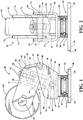
- the present invention provides a vertically-adjustable caster wheel apparatus 10 for use on various types of vehicles, including, but not limited to, forklift trucks (not shown), material handling carts (not shown), and the like.
- the caster wheel apparatus 10 provides a swivel bearing assembly 12 that is connected to a vehicle (not shown).
- a yolk frame 14 is rotatably connected to the swivel bearing assembly 12 and is pivotally connected to a wheel frame 16 through the use of a hinge pin 18.
- a wheel or roller 20 is rotatably connected to the wheel frame 16 by an axle 22.
- An elastic compression assembly 24 is pivotally connected to the yolk frame 14 and connected to a means for adjusting 26 the vertical height of the wheel 20.
- the vertical height adjusting means 26 is in turn connected to the wheel frame 16.
- the elastic compression assembly 24 assists in absorbing loads and forces applied to the wheel 20 of the caster wheel apparatus 10 so as to improve the performance of the caster wheel apparatus 10.
- the vertical height adjusting means 26 allows for the adjustment of the angle between the wheel frame 16 and the yolk frame 14, thereby adjusting the vertical height of the wheel 20 relative to the vehicle.
- the vertical height adjusting means 26 provides vertical height adjustment of the wheel 20 without having to completely disassemble and reassemble the caster wheel apparatus 10.
- the swivel bearing assembly 12 of the caster wheel apparatus 10 allows the caster wheel apparatus 10 to rotate with respect to the vehicle.
- the caster wheel apparatus 10 may be rigidly connected to the vehicle so that the caster wheel apparatus does not rotate with respect to the vehicle.
- the swivel bearing assembly 12 provides a substantially rectangular mounting plate 28 having four apertures 30 extending therethrough. Conventional fasteners (not shown) may be inserted through the apertures 30 in the mounting plate 28 and into the vehicle to secure the mounting plate 28 to the vehicle.
- a substantially cylindrical casing 32 is connected to and extends outward from the mounting plate 28 of the swivel bearing assembly 12.
- a swivel bearing 34 is mounted within an arcuate recess provided within the cylinder casing 32.
- the swivel bearing 34 and the casing 32 receive a substantially cylindrical portion 36 of the yolk frame 14, thereby securing the yolk frame 14 to the swivel bearing assembly 12 while also allowing the yolk frame 14 and the remaining portion of the caster wheel apparatus 10 to rotate with respect to the swivel bearing assembly 12 and the vehicle.
- the yolk frame 14 provides a substantially U-shaped configuration having a bottom side 38 and a pair of substantially parallel side walls 40 integrally connected to and extending away from the bottom side 38 of the folk frame 14.
- the underside of the bottom side 38 of the yolk frame 14 is connected to the cylindrical portion 36 of the yolk frame 14 which is received by the swivel bearing 34 of the swivel bearing assembly 12, as previously described.
- the side walls 40 of the yolk frame 14 may have a substantially J-shaped configuration such that a pair of flanges or short side of the J-shaped configurations 41 rise from the bottom side 38 of the yolk frame 14, as seen in FIGS. 1-5 .
- the side walls 40 of the yolk frame 14 may be substantially straight, wherein a pair of bosses 43 may be connected to an inside surface of the side walls 40 of the yolk frame 14, as seen in FIG. 6 .
- the side walls 40 of the yolk frame 14 each have a pair of apertures 42, 44 extending through the side walls 40, wherein the apertures 42, 44 are coaxially aligned in each of the side walls 40 of the yolk frame 14.
- the apertures 42 may extend through the flanges 41, as seen in FIGS. 1-5 , or the bosses 43, as seen in FIG. 6 , and the apertures 44 may extend through the side walls 40 of the yolk frame 14.
- Each set of apertures 42, 44 receives a pivot pin 46, 48 that extends across the yolk frame 14 through each of the pair of apertures 42, 44.
- the pivot pins 46, 48 may be secured to the yolk frame 14 through conventional means, such as providing a tab 50 connected to one end of the pivot pins 46, 48 and inserting a conventional fastener 52 through an aperture 54 provided in the tab 50 of the pivot pins 46, 48.
- the fasteners 52 may be received by a threaded aperture (not shown) in the side walls 40 of the yolk frame 14.
- the pivot pin 46 may secure the elastic assembly 24 to the yolk frame 14 by having the pivot pin 46 extend through a substantially first cylindrical portion 56 of a lower retainer 58 of the elastic assembly 24.
- the lower retainer 58 of the elastic assembly 24 has a second substantially cylindrical portion 60 connected to the first cylindrical portion 56.
- the first cylindrical portion 56 of the lower retainer 58 has a longitudinal axis that is coaxial with a longitudinal axis of the pivot pin 46, whereas the second cylindrical portion 60 of the lower retainer 58 has a longitudinal axis that is perpendicular to the longitudinal axis of the first cylindrical portion 56.
- the wheel frame 16 provides a pair of opposing and substantially parallel plates 62.
- the plates 62 have a pair of coaxially aligned apertures 64 extending therethrough for receiving the pivot pin 48 of the yolk frame 14.
- the pivot pin 48 allows the wheel frame 16 to pivot with respect to the yolk frame 14.
- the wheel frame 16 provides an additional pair of coaxially-aligned apertures 66 extending through the plates 62.
- the apertures 66 receive the axle 22 of the wheel 20 for rotatably supporting the wheel 20 with respect to the wheel frame 16.
- a set of bearings 68 and washers 70 may be provided on each side of the wheel 20 and mounted to the axle 22 to assist in the rolling of the wheel 20 with respect to the axle 20.
- the elastic assembly 24 includes a substantially cylindrical elastic member, such as a polyurethane tube 74, that is press fit onto the cylindrical portion 60 of the lower retainer 58. It is also anticipated that the elastic member 74 may take on different shapes and configurations and comprise a plurality of elastic members 74 stacked in a gang type application to create different spring rates of the elastic member 74.
- the cylindrical portion 60 of the lower retainer 50 may include a raised protuberance 75 for maintaining the lower retainer 58 on the polyurethane tube 74 after being press fit into a corresponding annular recess provided in the polyurethane tube 74.
- the lower retainer 58 includes a base portion 72 which extends outward from the cylindrical portion 60 of the lower retainer 58 such that one end of the polyurethane tube 74 abuts the base portion 72 of the lower retainer 58.
- an upper retainer 76 is press fit into the opposite end of the polyurethane tube 74.
- the upper retainer 76 also has a raised protuberance 77 for maintaining the upper retainer 76 within the polyurethane tube 74 after being press fit into a corresponding annular recess provided in the polyurethane tube 74.
- the upper retainer 76 also has a substantially cylindrical portion 78 that is received by the polyurethane tube 74 and a base portion 80 that abuts the end of the polyurethane tube 74.
- the cylindrical portion 78 of the upper retainer 76 has a threaded aperture 81 extending through the upper retainer 76 along a longitudinal axis of the upper retainer 76.
- the end of the cylindrical portion 78 of the upper retainer 76 and the end of the cylindrical portion 60 of the lower retainer 58 are spaced within the polyurethane tube 74.
- the polyurethane tube 74 is not extensively compressed thereby maintaining the spacing between the ends of the lower retainer 58 and the upper retainer 76.
- the polyurethane tube 74 extensively compresses, thereby allowing the ends of the cylindrical portion 78 of the upper retainer 76 and the cylindrical portion 60 of the lower retainer 58 to engage and abut one another to prevent the polyurethane tube 74 from being overloaded.
- FIGS. 1-3 To provide vertical adjustment of the wheel 20 of the caster wheel apparatus 10, a first embodiment of the vertical adjusting means 26 of the caster wheel apparatus 10 is shown in FIGS. 1-3 .
- the vertical adjusting means 26 To connect the elastic assembly 24 to the wheel frame 16, the vertical adjusting means 26 provides a swivel plate 82 having a substantially cylindrical body portion 84 with a threaded aperture extending therethrough.
- a pair of substantially cylindrical rods 86 extend integrally outward from the cylindrical portion 84 of the swivel plate 82.
- the rods 86 of the swivel plate 82 are received by a pair of coaxially aligned apertures 88 provided in the plates 62 of the wheel frame 16.
- Steel washers or spacers 90 may be inserted on one or both sides of the swivel plate 82 and are placed atop the upper retainer 76 of the elastic assembly 24.
- a threaded fastener or bolt 92 is inserted through the steel washers 90 and threaded through the threaded apertures in the cylindrical portion 84 of the swivel plate 82 and into the threaded aperture provided in the cylindrical portion 78 of the upper retainer 76 of the elastic assembly 24.
- the steel washers 90 are used as spacers in the vertical adjusting means 26. In order to raise the vertical height of the wheel 20 with respect to the vehicle, more washers 90 are simply added to the assembly by unthreading the fastener 92 and adding additional washers 90 to the fastener 92.
- the fastener 92 is removed, and the desired number of washers 90 are removed from the fastener 92. This provides an easy and simple manner in which to adjust the vertical height of the wheel 20 of the caster wheel apparatus 10 without having to fully disassemble and re-assemble the caster wheel apparatus 10.
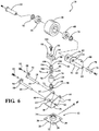
- the vertical adjusting means 26 may also take on a different structure, as shown in the second embodiment of the present invention in FIGS. 4-6 .
- the vertical adjusting means 26 provides a floating retainer 94 having a substantially U-shaped plate-like configuration with a threaded aperture 96 extending therethrough.
- a pair of substantially cylindrical rods 98 are integrally connected to and extend outwardly from the floating retainer 94.
- the rods 98 of the floating retainer 94 are received by the coaxial apertures 88 provided in the plates 62 of the wheel frame 16. This allows the elastic assembly 24 to pivot with respect to the wheel frame 16.
- a swivel lock nut 100 having a threaded aperture 102 extending therethrough is aligned with and connected to the underside of the floating retainer 94 in the upper retainer 76 of the elastic assembly 24.
- the swivel lock nut 100 has a similar configuration to that of the upper retainer 76 wherein a substantially cylindrical portion 104 is connected to a broader cylindrical base 106.
- a threaded fastener 108 is threaded through the aperture 96 provided in the floating retainer 94 and through the threaded aperture 102 provided in the swivel lock nut 100 and the threaded aperture in the upper retainer 76.
- the swivel lock nut 100 and the floating retainer 94 allow the threaded fastener 108 to be threaded in and out of the vertical adjustment means 26, thereby adjusting the vertical height of the wheel 20 by adjusting the angle between the wheel frame 16 and the yolk frame 14.
- This particular embodiment has the advantage of not having to remove the fastener 108 from the caster wheel apparatus 10, but rather, the vertical height of the wheel 20 may be adjusted by simply turning the fastener 108 of the vertical adjustment means 26.
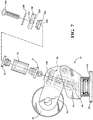
- the threaded fastener 108 may be locked in a set position, as shown in FIGS. 7-10 .
- the caster wheel apparatus 10 is similar to the embodiment described in FIGS. 4-6 ; however, the adjusting means 26 provides a floating retainer 110 having a plate-like configuration with a pair of rods112 extending from each side of the floating retainer110. The rods 112 engage the apertures 88 in the wheel frame 16, as previously described.
- the floating retainer 110 has a stepped inner aperture 114 for matingly receiving a swivel lock nut 116 having a stepped outer diameter that is connected to the floating retainer 110.
- the swivel lock nut 116 has a threaded aperture 118 extending there through for threadably receiving the threaded fastener 108.
- a washer 120 is connected to the underside of the head of the threaded fastener 108 such that the washer 120 abuts the floating retainer 110 when the threaded fastener 108 is fully threaded into the threaded aperture 118 of the swivel lock nut 116.
- the floating retainer 110 also has a threaded aperture 122 extending through one side of the floating retainer 110.
- the threaded aperture 122 threadably receives a set screw 124, wherein the head of the set screw 124 engages an arcuate recess 126 provided on an outer circumference of the washer 120.
- the washer 120 may have numerous arcuate recesses 126 formed on the washer 120.
- FIG. 9 shows four arcuate recesses 126 spaced at 90° degree intervals on the washer 120; however, the present invention anticipates different positions and intervals of the arcuate recesses 126 on the washer 120.
- the set screw 124 is loosened or threaded away from the floating retainer 110 such that the head of the set screw 124 no longer engages the arcuate recess 126 formed in the washer 120. This allows the threaded fastener 108 to turn thereby adjusting the vertical height of the wheel 20. This is defined as the unlocked position. Once a desired position of the wheel is achieved, the set screw 124 is threaded back into the floating retainer 110 so as to engage one of the arcuate recesses 126 in the washer 120 thereby locking the wheel 20 in a set position.
- the caster wheel apparatus 10 of the present invention is mounted to a vehicle by mounting the mounting plate 28 of the swivel bearing assembly 12 to the vehicle through the use of conventional fasteners.
- the vertical height of the wheel 20 may be adjusted by removing the fastener 92 and inserting or removing washers 90 between the swivel plate 82 and the upper retainer 76. Once the proper number of washers 90 are in place, the fastener 92 is threaded back into the vertical adjusting means 26.
- the vertical height of the wheel 20 is adjusted by simply threading the fastener 108 into or out of the vertical adjusting means 26 until the wheel 20 has reached the desired height.
- the set screw 124 may be utilized to prevent the threaded fastener 108 from rotating thereby locking the vertical height of the wheel 20 into position.
Landscapes
- Engineering & Computer Science (AREA)
- Mechanical Engineering (AREA)
- Handcart (AREA)
Claims (9)
- Höhenverstellbare Schwenkrolle (10) mit einem Gabelrahmen (14) und einem Radgestell (16), wobei der Gabelrahmen (14) einen Schwenkstift (46) aufweist, der mit dem Gabelrahmen (14) verbunden ist und sich durch diesen erstreckt, und das Radgestell (16) ein Ende, das schwenkend mit dem Gabelrahmen (14) verbunden ist, und ein zweites Ende, das drehbar mit einem Rad (20) verbunden ist, aufweist, umfassend:ein elastisches Element (24) mit einer ersten Haltevorrichtung (58), die mit einem Ende des elastischen Elements (24) verbunden ist, und einer zweiten Haltevorrichtung (76), die mit einem entgegengesetzten Ende des elastischen Elements (24) verbunden ist, worin die erste Haltevorrichtung (58) mit dem Schwenkstift (46) des Gabelrahmens (14) verbunden ist, damit das elastische Element (24) mit Bezug auf den Gabelrahmen (14) schwenken kann, dadurch gekennzeichnet, dass die zweite Haltevorrichtung (76) eine Gewindeöffnung (81) aufweist, die sich entlang einer Längsachse dort hindurch erstreckt;eine Schwenkplatte (82), die mit dem Radgestell (16) gekoppelt ist und eine Gewindeöffnung aufweist, die sich dort hindurch und koaxial zu der Längsachse erstreckt;ein Gewindebefestigungselement (92), das lösbar in die Gewindeöffnung in der Schwenkplatte (82) und die Gewindeöffnung in der zweiten Haltevorrichtung (76) eingreift; undein Distanzstück (90) mit Positionierung zwischen der zweiten Haltevorrichtung (76) und der Schwenkplatte (82) zum Einstellen einer vertikalen Höhe des Rades (20) durch Einstellen eines Winkels des Radgestells (16) relativ zu dem Gabelrahmen (14).
- Höhenverstellbare Schwenkrolle (10) wie Anspruch 1 angegeben, wobei das Distanzstück (90) ferner umfasst:
mindestens eine Unterlegscheibe (90) mit einem Durchlass zum Aufnehmen des Gewindebefestigungselements (92). - Höhenverstellbare Schwenkrolle (10) wie Anspruch 1 angegeben, ferner umfassend:
die Schwenkplatte (82) mit einem Paar Stangen (86), das durch ein Paar Öffnungen (88) in dem Radgestell (16) aufgenommen wird, um Drehung der Schwenkplatte (82) relativ zu dem Radgestell (16) zu erlauben. - Höhenverstellbare Schwenkrolle (10) wie Anspruch 1 angegeben, ferner umfassend:
eine Schwenklageranordnung (12), die mit dem Gabelrahmen (14) zum drehbaren Lagern des Gabelrahmens (14) gekoppelt ist. - Höhenverstellbare Schwenkrolle (10) wie Anspruch 1 angegeben, ferner umfassend:
das elastische Element (24), das aus einem Polyurethanmaterial hergestellt ist. - Höhenverstellbare Schwenkrolle (10) wie Anspruch 1 angegeben, wobei das elastische Element (24) ferner umfasst:
mindestens ein im Wesentlichen zylindrisches Polyurethanrohr (74). - Höhenverstellbare Schwenkrolle (10) wie Anspruch 1 angegeben, ferner umfassend:das elastische Element (24) mit einer im Wesentlichen zylindrischen Konfiguration mit einer Öffnung, die sich entlang einer Längsachse dort hindurch erstreckt;die erste Haltevorrichtung (58), die von der Öffnung an einem Ende des elastischen Elements aufgenommen wird, und die zweite Haltevorrichtung (76), die von der Öffnung an dem entgegengesetzten Ende des elastischen Elements aufgenommen wird; unddie erste Haltevorrichtung (58) und die zweite Haltevorrichtung (76), die in der Öffnung des elastischen Elements (24) beabstandet sind, wenn das elastische Element (24) nicht extensiv komprimiert ist, und die erste Haltevorrichtung (58) und die zweite Haltevorrichtung (76), die in der Öffnung des elastischen Elements (24) ineinandergreifen, wenn das elastische Element (24) extensiv komprimiert ist.
- Höhenverstellbare Schwenkrolle (10) wie Anspruch 7 angegeben, ferner umfassend:
die erste Haltevorrichtung (58) und die zweite Haltevorrichtung (76), die jeweils einen sich von dort erstreckenden ringförmigen Vorsprung (75, 77) aufweisen, und die erste Haltevorrichtung (58) und die zweite Haltevorrichtung (76), die den ringförmigen Vorsprung (75, 77) mit Presspassung in die Öffnung des elastischen Elements (24) aufweisen, um Bewegung der ersten Haltevorrichtung (58) und der zweiten Haltevorrichtung (76) relativ zu dem elastischen Element (24) zu verhindern. - Höhenverstellbare Schwenkrolle (10) nach Anspruch 1, ferner umfassend:das Radgestell (16), das schwenkend mit dem Gabelrahmen (14) über einen zweiten Schwenkstift (48) verbunden ist;das elastische Element (24) mit einem im Wesentlichen zylindrischen Polyurethanrohr (74), das eine Öffnung aufweist, die sich entlang einer Längsachse dort hindurch erstreckt; unddie erste Haltevorrichtung (58), die von dem Durchlass an einem Ende des Polyurethanrohres (74) aufgenommen wird, und die zweite Haltevorrichtung (76), die von dem Durchlass an einem entgegengesetzten Ende des Polyurethanrohres (24) aufgenommen wird, worin die erste Haltevorrichtung (58) mit dem Schwenkstift (46) des Gabelrahmens (14) verbunden ist, damit das Polyurethanrohr (74) mit Bezug auf den Gabelrahmen (14) schwenken kann.
Priority Applications (1)
| Application Number | Priority Date | Filing Date | Title |
|---|---|---|---|
| PL13795320T PL2909047T3 (pl) | 2012-10-19 | 2013-10-21 | Mechanizm do regulacji w pionie kółka samonastawnego |
Applications Claiming Priority (2)
| Application Number | Priority Date | Filing Date | Title |
|---|---|---|---|
| US201261716040P | 2012-10-19 | 2012-10-19 | |
| PCT/US2013/065926 WO2014063152A1 (en) | 2012-10-19 | 2013-10-21 | Vertically adjustable caster wheel apparatus |
Publications (2)
| Publication Number | Publication Date |
|---|---|
| EP2909047A1 EP2909047A1 (de) | 2015-08-26 |
| EP2909047B1 true EP2909047B1 (de) | 2019-08-14 |
Family
ID=50483997
Family Applications (1)
| Application Number | Title | Priority Date | Filing Date |
|---|---|---|---|
| EP13795320.4A Active EP2909047B1 (de) | 2012-10-19 | 2013-10-21 | Höhenverstellbare schwenkrolle |
Country Status (4)
| Country | Link |
|---|---|
| US (1) | US8839487B2 (de) |
| EP (1) | EP2909047B1 (de) |
| PL (1) | PL2909047T3 (de) |
| WO (1) | WO2014063152A1 (de) |
Families Citing this family (13)
| Publication number | Priority date | Publication date | Assignee | Title |
|---|---|---|---|---|
| ES2694663T3 (es) | 2013-03-06 | 2018-12-26 | Gatekeeper Systems, Inc. | Ruedas para vehículos no motorizados |
| US20140265283A1 (en) * | 2013-03-15 | 2014-09-18 | Jeff Tad Clifton | Service Vehicle Operation Training System and Method |
| KR101504241B1 (ko) * | 2014-10-15 | 2015-03-19 | 오준석 | 캐스터 및 캐스터를 포함하는 화이트 보드 |
| US10085903B1 (en) * | 2016-07-14 | 2018-10-02 | Ki Mobility | Angle adjustment assembly |
| US9956822B1 (en) * | 2016-12-22 | 2018-05-01 | Olympia International, Inc. | Wheel assembly for luggage |
| US10308068B2 (en) | 2017-05-03 | 2019-06-04 | Snap-On Incorporated | Suspension caster |
| US10717324B2 (en) | 2017-09-26 | 2020-07-21 | Ross Design & Engineering, Inc. | Vertically adjustable caster wheel |
| US10155415B1 (en) * | 2017-12-13 | 2018-12-18 | Kuo-Yu Lu | Shockproof caster |
| EP3593777B1 (de) * | 2018-07-10 | 2021-05-26 | TRUMPF Medizin Systeme GmbH + Co. KG | Rollenaufhängungssystem |
| US11712924B2 (en) | 2019-11-13 | 2023-08-01 | Superior Tire and Rubber Corp. | Caster assembly |
| US11333038B2 (en) * | 2020-01-09 | 2022-05-17 | Hamilton Sundstrand Corporation | Vibration isolation of linear hydraulic actuators using dual load path brackets |
| CA3106917A1 (en) * | 2020-01-24 | 2021-07-24 | Gatekeeper Systems, Inc. | Self-adjusting caster assemblies |
| US12172468B2 (en) * | 2023-02-24 | 2024-12-24 | Snap-On Incorporated | Adjustable wheel assembly |
Family Cites Families (48)
| Publication number | Priority date | Publication date | Assignee | Title |
|---|---|---|---|---|
| US1835144A (en) * | 1928-12-08 | 1931-12-08 | George A Cleaveland | Adjustable swivel caster |
| US2227875A (en) * | 1938-07-08 | 1941-01-07 | Cecil W Boden | Trailer for road vehicles |
| FR852602A (fr) | 1939-04-04 | 1940-02-28 | Support de roue pivotant | |
| US2494019A (en) * | 1945-01-05 | 1950-01-10 | Chicago Roller Skate Co | Roller skate resilient hanger structure |
| FR945777A (fr) * | 1947-04-15 | 1949-05-13 | Brevets J A Gregoire Soc D | Perfectionnements aux dispositifs de suspension des véhicules |
| US2507980A (en) * | 1947-08-18 | 1950-05-16 | Walter H Knapp | Independent wheel suspension |
| US2707795A (en) * | 1951-07-28 | 1955-05-10 | Faultless Caster Corp | Spring caster |
| US2738542A (en) * | 1952-04-21 | 1956-03-20 | Harry I Clark | Shock absorbing caster |
| US2885720A (en) * | 1955-11-04 | 1959-05-12 | George J Segal | Caster |
| FR2399328A1 (fr) | 1977-08-02 | 1979-03-02 | Hervieu | Roulettes a suspension |
| JPS5660707A (en) | 1979-10-19 | 1981-05-25 | Chuo Spring Co Ltd | Suspension for automobile |
| ATE42507T1 (de) * | 1985-08-23 | 1989-05-15 | Jd Technologie Ag | Federnde und schwenkbare lenkrolle. |
| GB2187687A (en) * | 1985-11-19 | 1987-09-16 | Domestic & General Finance Co | Trailer with damped caster wheel |
| DE3628838A1 (de) * | 1986-08-25 | 1988-03-03 | Wolf Woco & Co Franz J | Feder |
| EP0296326B1 (de) | 1987-06-09 | 1992-12-09 | Heinrich Blickle GmbH & Co.KG | Gefederte Schwerlastrolle |
| DE3839433C1 (de) | 1988-11-23 | 1989-10-19 | Carl Hurth Maschinen- Und Zahnradfabrik Gmbh & Co, 8000 Muenchen, De | |
| FR2655109B1 (fr) * | 1989-11-24 | 1994-02-04 | Paulstra Gmbh | Element elastique de support raideurs echelonnees. |
| JPH06127201A (ja) | 1992-10-15 | 1994-05-10 | Suehiro Giken Kk | キャスター |
| US5347680A (en) * | 1993-02-08 | 1994-09-20 | Northrop Corporation | Spring retracting caster |
| US5400469A (en) | 1993-04-22 | 1995-03-28 | Fki Industries, Inc. | Lever action caster with shock absorbing spring |
| DE29501456U1 (de) | 1994-02-03 | 1995-03-23 | Acla-Werke GmbH, 51065 Köln | Lenkrolle |
| US6149169A (en) * | 1997-04-08 | 2000-11-21 | Frog Legs, Inc. | Caster fork with dampener |
| DE19741742C2 (de) | 1997-09-22 | 2000-02-17 | Jungheinrich Ag | Gabelhubwagen mit Stützrad |
| DE19753412C2 (de) | 1997-12-02 | 2001-03-22 | Jungheinrich Ag | Gabelhubwagen mit verstellbarer Stützrolle |
| DE19753411B4 (de) | 1997-12-02 | 2004-02-12 | Jungheinrich Ag | Flurförderzeug |
| CN1180944C (zh) * | 1999-02-08 | 2004-12-22 | 萱场工业株式会社 | 小脚轮 |
| JP2001001705A (ja) | 1999-06-15 | 2001-01-09 | Toyota Autom Loom Works Ltd | 搬送車用キャスタ |
| US6543798B2 (en) * | 2000-04-04 | 2003-04-08 | Pride Mobility Products Corporation | Anti-tip caster suspension for a wheelchair |
| JP2001277807A (ja) * | 2000-04-04 | 2001-10-10 | Kayaba Ind Co Ltd | キャスター |
| US6425161B1 (en) | 2000-06-13 | 2002-07-30 | Superior Tire & Rubber Corporation | Industrial caster wheel with elastomeric spring/damper member |
| US6279199B1 (en) * | 2000-06-13 | 2001-08-28 | Ross Design & Engineering, Inc. | Vertically adjustable caster |
| US6460641B1 (en) | 2000-06-29 | 2002-10-08 | Invacare Corporation | Mid-wheel drive wheelchair with front wheel multiple bias suspension and anti-tip assembly |
| US6607201B2 (en) * | 2001-01-03 | 2003-08-19 | Bill W. Marshburn | Swivel wheel assembly with adjustable shock absorption |
| DE20100404U1 (de) | 2001-01-10 | 2001-03-15 | Gigga Corp., Taipeh/T'ai-Pei | Fahrradstoßdämpfer |
| US6499184B2 (en) | 2001-05-14 | 2002-12-31 | Ross Design & Engineering, Inc. | Elastomeric biased caster |
| US7093319B2 (en) * | 2002-06-28 | 2006-08-22 | Superior Tire & Rubber Corporation | Industrial caster wheel with elastomeric spring/damper member and adjustment member |
| JP3661169B2 (ja) * | 2002-07-04 | 2005-06-15 | ハンマーキャスター株式会社 | キャスター |
| KR100441165B1 (ko) | 2002-07-22 | 2004-07-21 | 명광산업주식회사 | 캐스터 완충장치 |
| US6892421B2 (en) * | 2002-12-11 | 2005-05-17 | The United States Of America As Represented By The Department Of Veterans Affairs | Oblique angled suspension caster fork for wheelchairs |
| US20060117524A1 (en) * | 2004-12-07 | 2006-06-08 | Li-Lan Yan | Structure of a shock absorbing caster |
| KR200412713Y1 (ko) * | 2005-12-28 | 2006-03-31 | 삼송공업 주식회사 | 캐스터의 완충장치 |
| US8490242B2 (en) | 2007-02-23 | 2013-07-23 | Universit Of Pittsburgh—Of the Commonwealth System of Higher Education | Mobile caster |
| JP2008307916A (ja) * | 2007-06-12 | 2008-12-25 | Sanyo Super Stand Co Ltd | キャスター |
| US20090205164A1 (en) * | 2008-02-19 | 2009-08-20 | Larson Albert W | Castor Wheel Assembly |
| JP2010149653A (ja) * | 2008-12-25 | 2010-07-08 | Matsunaga Seisakusho:Kk | 衝撃吸収キャスター |
| AU2009100069A4 (en) | 2009-01-28 | 2009-03-05 | Caremed Supply, Inc. | Bed frame with ergonomic retraction, reactive mattress retainers and shock isolated caster mounts |
| JP2012101650A (ja) * | 2010-11-09 | 2012-05-31 | Sumitomo Rubber Ind Ltd | キャスター |
| JP5486480B2 (ja) | 2010-11-30 | 2014-05-07 | 株式会社ナンシン | 緩衝機構を有するキャスタ |
-
2013
- 2013-10-21 EP EP13795320.4A patent/EP2909047B1/de active Active
- 2013-10-21 WO PCT/US2013/065926 patent/WO2014063152A1/en not_active Ceased
- 2013-10-21 PL PL13795320T patent/PL2909047T3/pl unknown
- 2013-10-21 US US14/058,861 patent/US8839487B2/en active Active
Non-Patent Citations (1)
| Title |
|---|
| None * |
Also Published As
| Publication number | Publication date |
|---|---|
| EP2909047A1 (de) | 2015-08-26 |
| US20140109341A1 (en) | 2014-04-24 |
| US8839487B2 (en) | 2014-09-23 |
| HK1213226A1 (en) | 2016-06-30 |
| WO2014063152A1 (en) | 2014-04-24 |
| PL2909047T3 (pl) | 2020-02-28 |
Similar Documents
| Publication | Publication Date | Title |
|---|---|---|
| US8839487B2 (en) | Vertically adjustable caster wheel apparatus | |
| US7093319B2 (en) | Industrial caster wheel with elastomeric spring/damper member and adjustment member | |
| CA2880533C (en) | Motor vehicle axle suspension with longitudinal leaf spring | |
| US7537225B2 (en) | Adjustable suspension leveling apparatus | |
| US6499184B2 (en) | Elastomeric biased caster | |
| USRE30308E (en) | Suspension structure for automotive vehicles | |
| EP3892476B1 (de) | Radanordnung | |
| US3482854A (en) | Suspension structure for automotive vehicles | |
| US20090205164A1 (en) | Castor Wheel Assembly | |
| US20110131761A1 (en) | Caster Wheel System | |
| US20090243246A1 (en) | Suspension system with enhanced stability | |
| US20150369309A1 (en) | Brake Component Handling Apparatus | |
| US7770904B2 (en) | Stability system for an industrial vehicle | |
| AU2019444627B2 (en) | Crushing device | |
| EP3687833B1 (de) | Vertikaljustierbare lenkrolle | |
| CN205095855U (zh) | 磨辊轧距调节机构以及磨粉机 | |
| HK1213226B (en) | Vertically adjustable caster wheel apparatus | |
| US10499554B2 (en) | Anti wobbling castor support for a wheel | |
| WO2010119402A1 (en) | A supplementary vehicle spring assembly | |
| EP1868829B1 (de) | Stabilitätssystem für ein nutzfahrzeug | |
| CN219489512U (zh) | 一种用于叉车驱动轮的浮动结构 | |
| EP2332400B1 (de) | Zinkenaufnahme | |
| KR20180001176A (ko) | 캐스터 | |
| CN214087549U (zh) | 一种具有护脚板的手搬车 | |
| US11806603B1 (en) | Skateboard truck assembly |
Legal Events
| Date | Code | Title | Description |
|---|---|---|---|
| PUAI | Public reference made under article 153(3) epc to a published international application that has entered the european phase |
Free format text: ORIGINAL CODE: 0009012 |
|
| 17P | Request for examination filed |
Effective date: 20150507 |
|
| AK | Designated contracting states |
Kind code of ref document: A1 Designated state(s): AL AT BE BG CH CY CZ DE DK EE ES FI FR GB GR HR HU IE IS IT LI LT LU LV MC MK MT NL NO PL PT RO RS SE SI SK SM TR |
|
| AX | Request for extension of the european patent |
Extension state: BA ME |
|
| DAX | Request for extension of the european patent (deleted) | ||
| REG | Reference to a national code |
Ref country code: HK Ref legal event code: DE Ref document number: 1213226 Country of ref document: HK |
|
| STAA | Information on the status of an ep patent application or granted ep patent |
Free format text: STATUS: EXAMINATION IS IN PROGRESS |
|
| 17Q | First examination report despatched |
Effective date: 20170904 |
|
| GRAP | Despatch of communication of intention to grant a patent |
Free format text: ORIGINAL CODE: EPIDOSNIGR1 |
|
| STAA | Information on the status of an ep patent application or granted ep patent |
Free format text: STATUS: GRANT OF PATENT IS INTENDED |
|
| INTG | Intention to grant announced |
Effective date: 20190301 |
|
| GRAJ | Information related to disapproval of communication of intention to grant by the applicant or resumption of examination proceedings by the epo deleted |
Free format text: ORIGINAL CODE: EPIDOSDIGR1 |
|
| STAA | Information on the status of an ep patent application or granted ep patent |
Free format text: STATUS: EXAMINATION IS IN PROGRESS |
|
| GRAJ | Information related to disapproval of communication of intention to grant by the applicant or resumption of examination proceedings by the epo deleted |
Free format text: ORIGINAL CODE: EPIDOSDIGR1 |
|
| GRAP | Despatch of communication of intention to grant a patent |
Free format text: ORIGINAL CODE: EPIDOSNIGR1 |
|
| GRAS | Grant fee paid |
Free format text: ORIGINAL CODE: EPIDOSNIGR3 |
|
| INTC | Intention to grant announced (deleted) | ||
| GRAJ | Information related to disapproval of communication of intention to grant by the applicant or resumption of examination proceedings by the epo deleted |
Free format text: ORIGINAL CODE: EPIDOSDIGR1 |
|
| GRAP | Despatch of communication of intention to grant a patent |
Free format text: ORIGINAL CODE: EPIDOSNIGR1 |
|
| GRAS | Grant fee paid |
Free format text: ORIGINAL CODE: EPIDOSNIGR3 |
|
| GRAR | Information related to intention to grant a patent recorded |
Free format text: ORIGINAL CODE: EPIDOSNIGR71 |
|
| GRAS | Grant fee paid |
Free format text: ORIGINAL CODE: EPIDOSNIGR3 |
|
| STAA | Information on the status of an ep patent application or granted ep patent |
Free format text: STATUS: GRANT OF PATENT IS INTENDED |
|
| GRAA | (expected) grant |
Free format text: ORIGINAL CODE: 0009210 |
|
| STAA | Information on the status of an ep patent application or granted ep patent |
Free format text: STATUS: THE PATENT HAS BEEN GRANTED |
|
| AK | Designated contracting states |
Kind code of ref document: B1 Designated state(s): AL AT BE BG CH CY CZ DE DK EE ES FI FR GB GR HR HU IE IS IT LI LT LU LV MC MK MT NL NO PL PT RO RS SE SI SK SM TR |
|
| INTG | Intention to grant announced |
Effective date: 20190708 |
|
| REG | Reference to a national code |
Ref country code: GB Ref legal event code: FG4D |
|
| REG | Reference to a national code |
Ref country code: CH Ref legal event code: EP Ref country code: AT Ref legal event code: REF Ref document number: 1166577 Country of ref document: AT Kind code of ref document: T Effective date: 20190815 |
|
| REG | Reference to a national code |
Ref country code: IE Ref legal event code: FG4D |
|
| REG | Reference to a national code |
Ref country code: DE Ref legal event code: R096 Ref document number: 602013059213 Country of ref document: DE |
|
| REG | Reference to a national code |
Ref country code: SE Ref legal event code: TRGR |
|
| REG | Reference to a national code |
Ref country code: NL Ref legal event code: FP |
|
| REG | Reference to a national code |
Ref country code: LT Ref legal event code: MG4D |
|
| PG25 | Lapsed in a contracting state [announced via postgrant information from national office to epo] |
Ref country code: LT Free format text: LAPSE BECAUSE OF FAILURE TO SUBMIT A TRANSLATION OF THE DESCRIPTION OR TO PAY THE FEE WITHIN THE PRESCRIBED TIME-LIMIT Effective date: 20190814 Ref country code: HR Free format text: LAPSE BECAUSE OF FAILURE TO SUBMIT A TRANSLATION OF THE DESCRIPTION OR TO PAY THE FEE WITHIN THE PRESCRIBED TIME-LIMIT Effective date: 20190814 Ref country code: FI Free format text: LAPSE BECAUSE OF FAILURE TO SUBMIT A TRANSLATION OF THE DESCRIPTION OR TO PAY THE FEE WITHIN THE PRESCRIBED TIME-LIMIT Effective date: 20190814 Ref country code: NO Free format text: LAPSE BECAUSE OF FAILURE TO SUBMIT A TRANSLATION OF THE DESCRIPTION OR TO PAY THE FEE WITHIN THE PRESCRIBED TIME-LIMIT Effective date: 20191114 Ref country code: BG Free format text: LAPSE BECAUSE OF FAILURE TO SUBMIT A TRANSLATION OF THE DESCRIPTION OR TO PAY THE FEE WITHIN THE PRESCRIBED TIME-LIMIT Effective date: 20191114 Ref country code: PT Free format text: LAPSE BECAUSE OF FAILURE TO SUBMIT A TRANSLATION OF THE DESCRIPTION OR TO PAY THE FEE WITHIN THE PRESCRIBED TIME-LIMIT Effective date: 20191216 |
|
| REG | Reference to a national code |
Ref country code: AT Ref legal event code: MK05 Ref document number: 1166577 Country of ref document: AT Kind code of ref document: T Effective date: 20190814 |
|
| PG25 | Lapsed in a contracting state [announced via postgrant information from national office to epo] |
Ref country code: IS Free format text: LAPSE BECAUSE OF FAILURE TO SUBMIT A TRANSLATION OF THE DESCRIPTION OR TO PAY THE FEE WITHIN THE PRESCRIBED TIME-LIMIT Effective date: 20191214 Ref country code: RS Free format text: LAPSE BECAUSE OF FAILURE TO SUBMIT A TRANSLATION OF THE DESCRIPTION OR TO PAY THE FEE WITHIN THE PRESCRIBED TIME-LIMIT Effective date: 20190814 Ref country code: LV Free format text: LAPSE BECAUSE OF FAILURE TO SUBMIT A TRANSLATION OF THE DESCRIPTION OR TO PAY THE FEE WITHIN THE PRESCRIBED TIME-LIMIT Effective date: 20190814 Ref country code: GR Free format text: LAPSE BECAUSE OF FAILURE TO SUBMIT A TRANSLATION OF THE DESCRIPTION OR TO PAY THE FEE WITHIN THE PRESCRIBED TIME-LIMIT Effective date: 20191115 Ref country code: AL Free format text: LAPSE BECAUSE OF FAILURE TO SUBMIT A TRANSLATION OF THE DESCRIPTION OR TO PAY THE FEE WITHIN THE PRESCRIBED TIME-LIMIT Effective date: 20190814 Ref country code: ES Free format text: LAPSE BECAUSE OF FAILURE TO SUBMIT A TRANSLATION OF THE DESCRIPTION OR TO PAY THE FEE WITHIN THE PRESCRIBED TIME-LIMIT Effective date: 20190814 |
|
| PG25 | Lapsed in a contracting state [announced via postgrant information from national office to epo] |
Ref country code: TR Free format text: LAPSE BECAUSE OF FAILURE TO SUBMIT A TRANSLATION OF THE DESCRIPTION OR TO PAY THE FEE WITHIN THE PRESCRIBED TIME-LIMIT Effective date: 20190814 |
|
| PG25 | Lapsed in a contracting state [announced via postgrant information from national office to epo] |
Ref country code: AT Free format text: LAPSE BECAUSE OF FAILURE TO SUBMIT A TRANSLATION OF THE DESCRIPTION OR TO PAY THE FEE WITHIN THE PRESCRIBED TIME-LIMIT Effective date: 20190814 Ref country code: DK Free format text: LAPSE BECAUSE OF FAILURE TO SUBMIT A TRANSLATION OF THE DESCRIPTION OR TO PAY THE FEE WITHIN THE PRESCRIBED TIME-LIMIT Effective date: 20190814 Ref country code: EE Free format text: LAPSE BECAUSE OF FAILURE TO SUBMIT A TRANSLATION OF THE DESCRIPTION OR TO PAY THE FEE WITHIN THE PRESCRIBED TIME-LIMIT Effective date: 20190814 Ref country code: RO Free format text: LAPSE BECAUSE OF FAILURE TO SUBMIT A TRANSLATION OF THE DESCRIPTION OR TO PAY THE FEE WITHIN THE PRESCRIBED TIME-LIMIT Effective date: 20190814 |
|
| PG25 | Lapsed in a contracting state [announced via postgrant information from national office to epo] |
Ref country code: SM Free format text: LAPSE BECAUSE OF FAILURE TO SUBMIT A TRANSLATION OF THE DESCRIPTION OR TO PAY THE FEE WITHIN THE PRESCRIBED TIME-LIMIT Effective date: 20190814 Ref country code: SK Free format text: LAPSE BECAUSE OF FAILURE TO SUBMIT A TRANSLATION OF THE DESCRIPTION OR TO PAY THE FEE WITHIN THE PRESCRIBED TIME-LIMIT Effective date: 20190814 Ref country code: CZ Free format text: LAPSE BECAUSE OF FAILURE TO SUBMIT A TRANSLATION OF THE DESCRIPTION OR TO PAY THE FEE WITHIN THE PRESCRIBED TIME-LIMIT Effective date: 20190814 Ref country code: MC Free format text: LAPSE BECAUSE OF FAILURE TO SUBMIT A TRANSLATION OF THE DESCRIPTION OR TO PAY THE FEE WITHIN THE PRESCRIBED TIME-LIMIT Effective date: 20190814 Ref country code: IS Free format text: LAPSE BECAUSE OF FAILURE TO SUBMIT A TRANSLATION OF THE DESCRIPTION OR TO PAY THE FEE WITHIN THE PRESCRIBED TIME-LIMIT Effective date: 20200224 |
|
| REG | Reference to a national code |
Ref country code: CH Ref legal event code: PL |
|
| REG | Reference to a national code |
Ref country code: DE Ref legal event code: R097 Ref document number: 602013059213 Country of ref document: DE |
|
| PLBE | No opposition filed within time limit |
Free format text: ORIGINAL CODE: 0009261 |
|
| STAA | Information on the status of an ep patent application or granted ep patent |
Free format text: STATUS: NO OPPOSITION FILED WITHIN TIME LIMIT |
|
| PG2D | Information on lapse in contracting state deleted |
Ref country code: IS |
|
| PG25 | Lapsed in a contracting state [announced via postgrant information from national office to epo] |
Ref country code: CH Free format text: LAPSE BECAUSE OF NON-PAYMENT OF DUE FEES Effective date: 20191031 Ref country code: LU Free format text: LAPSE BECAUSE OF NON-PAYMENT OF DUE FEES Effective date: 20191021 Ref country code: LI Free format text: LAPSE BECAUSE OF NON-PAYMENT OF DUE FEES Effective date: 20191031 |
|
| 26N | No opposition filed |
Effective date: 20200603 |
|
| PG25 | Lapsed in a contracting state [announced via postgrant information from national office to epo] |
Ref country code: SI Free format text: LAPSE BECAUSE OF FAILURE TO SUBMIT A TRANSLATION OF THE DESCRIPTION OR TO PAY THE FEE WITHIN THE PRESCRIBED TIME-LIMIT Effective date: 20190814 |
|
| PG25 | Lapsed in a contracting state [announced via postgrant information from national office to epo] |
Ref country code: CY Free format text: LAPSE BECAUSE OF FAILURE TO SUBMIT A TRANSLATION OF THE DESCRIPTION OR TO PAY THE FEE WITHIN THE PRESCRIBED TIME-LIMIT Effective date: 20190814 |
|
| PG25 | Lapsed in a contracting state [announced via postgrant information from national office to epo] |
Ref country code: MT Free format text: LAPSE BECAUSE OF FAILURE TO SUBMIT A TRANSLATION OF THE DESCRIPTION OR TO PAY THE FEE WITHIN THE PRESCRIBED TIME-LIMIT Effective date: 20190814 Ref country code: HU Free format text: LAPSE BECAUSE OF FAILURE TO SUBMIT A TRANSLATION OF THE DESCRIPTION OR TO PAY THE FEE WITHIN THE PRESCRIBED TIME-LIMIT; INVALID AB INITIO Effective date: 20131021 |
|
| PG25 | Lapsed in a contracting state [announced via postgrant information from national office to epo] |
Ref country code: MK Free format text: LAPSE BECAUSE OF FAILURE TO SUBMIT A TRANSLATION OF THE DESCRIPTION OR TO PAY THE FEE WITHIN THE PRESCRIBED TIME-LIMIT Effective date: 20190814 |
|
| P01 | Opt-out of the competence of the unified patent court (upc) registered |
Effective date: 20230609 |
|
| P02 | Opt-out of the competence of the unified patent court (upc) changed |
Effective date: 20230621 |
|
| PGFP | Annual fee paid to national office [announced via postgrant information from national office to epo] |
Ref country code: NL Payment date: 20251026 Year of fee payment: 13 |
|
| PGFP | Annual fee paid to national office [announced via postgrant information from national office to epo] |
Ref country code: DE Payment date: 20251029 Year of fee payment: 13 |
|
| PGFP | Annual fee paid to national office [announced via postgrant information from national office to epo] |
Ref country code: GB Payment date: 20251027 Year of fee payment: 13 |
|
| PGFP | Annual fee paid to national office [announced via postgrant information from national office to epo] |
Ref country code: IT Payment date: 20251021 Year of fee payment: 13 |
|
| PGFP | Annual fee paid to national office [announced via postgrant information from national office to epo] |
Ref country code: FR Payment date: 20251027 Year of fee payment: 13 |
|
| PGFP | Annual fee paid to national office [announced via postgrant information from national office to epo] |
Ref country code: BE Payment date: 20251027 Year of fee payment: 13 |
|
| PGFP | Annual fee paid to national office [announced via postgrant information from national office to epo] |
Ref country code: SE Payment date: 20251027 Year of fee payment: 13 |
|
| PGFP | Annual fee paid to national office [announced via postgrant information from national office to epo] |
Ref country code: IE Payment date: 20251027 Year of fee payment: 13 |
|
| PGFP | Annual fee paid to national office [announced via postgrant information from national office to epo] |
Ref country code: PL Payment date: 20251001 Year of fee payment: 13 |