EP2908767B1 - System und verfahren zur entwicklung einer zahnkomponente - Google Patents
System und verfahren zur entwicklung einer zahnkomponente Download PDFInfo
- Publication number
- EP2908767B1 EP2908767B1 EP13783288.7A EP13783288A EP2908767B1 EP 2908767 B1 EP2908767 B1 EP 2908767B1 EP 13783288 A EP13783288 A EP 13783288A EP 2908767 B1 EP2908767 B1 EP 2908767B1
- Authority
- EP
- European Patent Office
- Prior art keywords
- patient
- representation
- jaws
- bite
- movement
- Prior art date
- Legal status (The legal status is an assumption and is not a legal conclusion. Google has not performed a legal analysis and makes no representation as to the accuracy of the status listed.)
- Active
Links
- 238000000034 method Methods 0.000 title claims description 51
- 230000033001 locomotion Effects 0.000 claims description 117
- 238000013461 design Methods 0.000 claims description 11
- 230000009466 transformation Effects 0.000 claims description 10
- 238000013519 translation Methods 0.000 claims description 3
- 238000000844 transformation Methods 0.000 claims description 2
- 238000009966 trimming Methods 0.000 claims 1
- 210000001847 jaw Anatomy 0.000 description 58
- 210000004373 mandible Anatomy 0.000 description 12
- 210000002050 maxilla Anatomy 0.000 description 10
- 238000012545 processing Methods 0.000 description 5
- 230000008901 benefit Effects 0.000 description 4
- 238000004590 computer program Methods 0.000 description 4
- 230000006870 function Effects 0.000 description 4
- 239000000463 material Substances 0.000 description 3
- 238000004088 simulation Methods 0.000 description 3
- 241000282465 Canis Species 0.000 description 2
- 230000003068 static effect Effects 0.000 description 2
- 230000014616 translation Effects 0.000 description 2
- 206010033372 Pain and discomfort Diseases 0.000 description 1
- 230000009471 action Effects 0.000 description 1
- 210000003484 anatomy Anatomy 0.000 description 1
- 230000001055 chewing effect Effects 0.000 description 1
- 238000002591 computed tomography Methods 0.000 description 1
- 238000012937 correction Methods 0.000 description 1
- 210000002455 dental arch Anatomy 0.000 description 1
- 210000004513 dentition Anatomy 0.000 description 1
- 230000001419 dependent effect Effects 0.000 description 1
- 230000004927 fusion Effects 0.000 description 1
- 238000012986 modification Methods 0.000 description 1
- 230000004048 modification Effects 0.000 description 1
- 210000003205 muscle Anatomy 0.000 description 1
- 238000005457 optimization Methods 0.000 description 1
- 230000000149 penetrating effect Effects 0.000 description 1
- 239000007787 solid Substances 0.000 description 1
- 230000036346 tooth eruption Effects 0.000 description 1
- 238000002604 ultrasonography Methods 0.000 description 1
- 230000000007 visual effect Effects 0.000 description 1
Images


Classifications
-
- A—HUMAN NECESSITIES
- A61—MEDICAL OR VETERINARY SCIENCE; HYGIENE
- A61C—DENTISTRY; APPARATUS OR METHODS FOR ORAL OR DENTAL HYGIENE
- A61C5/00—Filling or capping teeth
- A61C5/70—Tooth crowns; Making thereof
- A61C5/77—Methods or devices for making crowns
-
- A—HUMAN NECESSITIES
- A61—MEDICAL OR VETERINARY SCIENCE; HYGIENE
- A61C—DENTISTRY; APPARATUS OR METHODS FOR ORAL OR DENTAL HYGIENE
- A61C9/00—Impression cups, i.e. impression trays; Impression methods
- A61C9/004—Means or methods for taking digitized impressions
-
- A—HUMAN NECESSITIES
- A61—MEDICAL OR VETERINARY SCIENCE; HYGIENE
- A61C—DENTISTRY; APPARATUS OR METHODS FOR ORAL OR DENTAL HYGIENE
- A61C13/00—Dental prostheses; Making same
- A61C13/0003—Making bridge-work, inlays, implants or the like
- A61C13/0004—Computer-assisted sizing or machining of dental prostheses
-
- A—HUMAN NECESSITIES
- A61—MEDICAL OR VETERINARY SCIENCE; HYGIENE
- A61C—DENTISTRY; APPARATUS OR METHODS FOR ORAL OR DENTAL HYGIENE
- A61C13/00—Dental prostheses; Making same
- A61C13/34—Making or working of models, e.g. preliminary castings, trial dentures; Dowel pins [4]
-
- A—HUMAN NECESSITIES
- A61—MEDICAL OR VETERINARY SCIENCE; HYGIENE
- A61C—DENTISTRY; APPARATUS OR METHODS FOR ORAL OR DENTAL HYGIENE
- A61C19/00—Dental auxiliary appliances
- A61C19/04—Measuring instruments specially adapted for dentistry
- A61C19/05—Measuring instruments specially adapted for dentistry for determining occlusion
- A61C19/052—Measuring instruments specially adapted for dentistry for determining occlusion with tracing appliances
-
- A—HUMAN NECESSITIES
- A61—MEDICAL OR VETERINARY SCIENCE; HYGIENE
- A61C—DENTISTRY; APPARATUS OR METHODS FOR ORAL OR DENTAL HYGIENE
- A61C7/00—Orthodontics, i.e. obtaining or maintaining the desired position of teeth, e.g. by straightening, evening, regulating, separating, or by correcting malocclusions
- A61C7/002—Orthodontic computer assisted systems
Definitions
- This invention generally relates to a system and a method of digitally designing a dental component in the form of a dental restoration or an orthodontic appliance for a patient. More particularly, the invention relates to designing the dental component by obtaining different bite configurations of the patient's jaws.
- articulation relates to the movement of the teeth when they come in contact and to the arrangement of artificial teeth to simulate the natural teeth. See for example " Oxford Dictionary of Dentistry", First Edition 2010, ISBN 978-0-19-953301-5: articulation n. 1 . The jointed movement of the upper and lower teeth when they come into contact. 2. The arrangement of artificial teeth to simulate the natural dentition.
- restorations such artificial teeth, crowns, bridges, dentures etc. it is important that the articulation is maintained. If the articulation is not correct the patient may experience poor bite function, discomfort and/or pain, moreover, the restoration may crack or break.
- Articulators has been very common to use so-called articulators when designing restoration manually. Articulators comes in a variety of models and designs, however, common for them all is that they are used to simulate the articulation. Articulators comprises an upper part on which a model of the maxilla is attached and a lower part on which a model of the mandible is attached. The upper and lower parts are moveable relative to each other within certain restraints. Such restraints, or at least some of them, are in many types of articulators adjustable in order to allow the user to adjust and thereby obtaining a better simulation of the patient's articulation. The adjustable restraints which often are referred to as articulator parameters can be measured and obtained in many different ways.
- articulator parameter is the articulator axis around which the maxilla and mandibular model rotates and where facebows often are used to correctly place the models relative to this axis.
- Other such parameters can for example be the condylar guidance, the Bennett angle and Bennett shift.
- the description further relates to an alternative method of determining patient specific motion which is easy to apply and uses hardware which is used for other purposes and is becoming more and more common in the dental clinics and laboratories.
- WO 2011/103876 A1 discloses a computer-implemented method of using a dynamic virtual articulator for simulating occlusion of teeth, when performing computer-aided designing of one or more dental restorations for a patient, where the method comprises the steps of: - providing the virtual articulator comprising a virtual three-dimensional model of the upper jaw and a virtual three-dimensional model of the lower jaw resembling the upper jaw and lower jaw, respectively, of the patient' s mouth; - providing movement of the virtual upper jaw and the virtual lower jaw relative to each other for simulating dynamic occlusion, whereby collisions between teeth in the virtual upper and virtual lower jaw occur; wherein the method further comprises: providing that the teeth in the virtual upper jaw and virtual lower jaw are blocked from penetrating each other' s virtual surfaces in the collisions.
- the occlusal contact movement is estimated as it is in particular this movement which is relevant to maintain when designing restorations and other dental components in order to avoid pain and discomfort to the patient.
- the occlusal contact movement can advantageously be recorded. This allows for later playback in order to visualise the movement or use it in order to design the dental component.
- the bite configurations do not necessarily need to cover the entire bite of the upper and lower jaws.
- only part of the actual bite is used for the respective 3D representation of the bite configurations. This saves time and is especially advantageous when using intra-oral scanners. The application of the current method with intra-oral scanner will be discussed further herein.
- the respective 3D representations of bite configurations can be used to align the 3D representation of the patient's upper jaw and the 3D representation of the patient's lower jaw . Accordingly, when the occlusal contact movement of the jaws has been determined it can be used to visualize the movement on a monitor.
- Such alignment is well known in the art. Typically it is provided by an initial alignment and then followed by optimization, for example by using a ICP (Iterative Closest Point) algorithm. For more information see for example " Method for registration of 3-D shapes" by Paul J. Besl and Neil D. McKay, Proc.
- the teeth of the 3D representation of the patient's jaw can be used to define a reference, for example by tracing a surface, or limit, which defines a boundary to which the dental component can be designed without affecting the occlusal contact movement, and thus maintaining the patient specific motion even after restorative work.
- the occlusal contact movement can be used to design proper contacts and function for the component, such as a dental restoration, by playing the contact movement and adjusting the restoration to ensure proper contact and function for the restoration during motion.
- the designer can design the dental component so at least one contact area is provided between the dental component and the reference. In this way occlusal contact is achieved for the dental component and an opposing tooth or restoration when inserted into the mouth of the patient. This can be used to design good bite function where the dental components, such as the restoration, support the dynamic occlusion.
- the movement itself can be used as a boundary.
- the upper jaw can be treated as a solid object which during playing the occlusal contact motion basically cuts or digs away overlapping material from the dental component which prevents the occlusal contact motion from being played correctly.
- overlapping material may be identified, e.g. marking it in a red color, whereby it is up to the designer to decide whether the area should be removed or redesigned.
- the occlusal contact movement is the movement of the jaws where at least one area of contact between the teeth of the upper jaw (maxilla) and the teeth of the lower jaw (mandible) is maintained. This is often also referred to as the dynamic occlusion.
- More than two different bite configurations may be required in order to determine or estimate the occlusal contact movement of the patient's jaws relative to each other, such as three, four, five, six, seven, eight, nine, ten etc.
- the bite configurations can be recorded using an intra oral 3D scanner, such as 3Shape's TRIOS scanner.
- the dentist will ask the patient to bite his or her upper jaw and lower jaw together, and while the patient bites together in a first configuration, the dentist will perform a scanning of the patient's teeth by means of the intra oral scanner to acquire a first 3D representation. Then the dentist will ask the patient to bite his or her upper jaw and lower jaw together again, and while the patient bites together in a second configuration, the dentist will perform a scanning of the patient's teeth by means of the intra oral scanner to acquire a second 3D representation. If more bite configurations are desired or required for determining the occlusal contact movement of the jaws relative to each other, the dentist will ask the patient to bite together a third, fourth, fifth etc. time and perform a scanning for each bite.
- digitally determining the occlusal contact movement comprises a consecutive sequence of at least two 3D representations of bite configurations of the patient's jaws in respective occlusions.
- Such a sequence of bite configurations can for example be obtained by holding a scanner, such as the TRIOS scanner described above, against the teeth of the patient while the patient is moving the jaws in an occlusal contact movement.
- the TRIOS is then set to record a sequence of 3D scans during the occlusal contact movement.
- Each 3D scan can then be used to align the maxilla and mandible, whereafter the maxilla and mandible can be displayed in their respective alignment in a sequence corresponding to the sequence wherein the bite configurations were obtained during the recorded sequence of 3D scans.
- the method comprises obtaining a plurality of 3D representations of bite configurations of the patient's jaw using an intra-oral scanner.
- the frames can for example be used to generate an animation showing the movement of jaws
- the frame can advantageously be a 3D frame, ie. where the upper and lower jaws has been aligned with their respective bite configurations, whereby the 3D representations of the upper and lower jaw can be rotated .
- the frames can alternatively be a 2D image.
- the plurality or consecutive sequence of 3D representations of bite configurations can be used to directly determine the occlusal contact motion if they are taken with an interval sufficiently short for generating an occlusal contact motion with a resolution which is high enough for a given application.
- the occlusal contact movement of the 3D representations are adapted to be played as a video stream.
- the speed can be altered for example showing it in slow motion.
- the method as described herein is thus particularly advantageously used together with an intra-oral scanner as this can obtain the 3D representation of the jaws and the bite registrations.
- the intra-oral scanner is used by the dentist or dental technician for many other purposes and is thus an instrument which is becoming very versatile in its use.
- the bite configurations can also be obtained by means of the dentist taking a physical impression, using impression material, in the patient's mouth for each different bites configuration.
- the impressions should then be scanned in for example a 3D desktop scanner afterwards to obtain the 3D representations of the different bite configurations.
- the method of digitally designing the dental component will typically be performed by a dental technician using a software CAD program running on a computer, such as 3Shape's Dental System CAD software.
- the dental technician will typically obtain the different 3D representations, i.e.
- the dental technician can then design the dental component, or the component can be automatically designed by the software program.
- the different 3D representations can be obtained as computer files from the dentist, if the dentist has performed the scanning using an intra oral 3D scanner. If physical impressions were made, then the impressions can be scanned by the dental technician him/herself in the dental laboratory, and the 3D representations obtained by the scanning can then be obtained as computer files and loaded into the computer for use in the software CAD program.
- the method may be a computer-implemented method. According to the invention, digitally determining occlusal contact movement of the patient's jaws relative to each other comprises interpolating the movement between the measured bite configurations.
- the interpolation is a linear interpolation of the position and rotation/angles of the jaws over a number of steps.
- the number of steps can be decided based on the numbers and/or distance between the 3D representations of the bite registrations. A higher number of steps will result in an occlusal contact movement with a higher resolution, however, more processing power is necessary.
- the interpolation comprises performing a rigid transformation.
- the interpolation comprises performing a linear transformation.
- the interpolation comprises performing a non-linear transformation.
- the interpolation is a combination of linear and non-linear transformations.
- the transformation comprises translation and rotation.
- the interpolation is performed with regard to teeth present within the range of known data points from at least the first and the second bite configurations. If a tooth is present along the path of the interpolation, then the interpolation will be a non-linear translations and/or rotation. In other words, if it during interpolation is detected that teeth will collide, i.e. those areas of the 3D representations will overlap which would be impossible in the physical world, then interpolation will move the jaws so that the overlap is avoided in order to ensure proper contact.
- the method further comprises
- the method further comprises
- the occlusal contact movement of the patient's jaws comprise:
- the occlusal contact motion is played in the order it was determined. E.g. if the occlusal contact motion was determined by first taking lateral 3D representations of bite registrations, followed by 3D representation of bite registration taken during protrusion and finally 3D representations of bite registrations taken during retrusion, the occlusal contact motion will be played in that same sequence. This increases the accuracy of the occlusal contact motion since the motion may be slightly different if played the other way around due to anatomy such as muscle movement, jaw configuration etc.
- the risk of losing the higher accuracy may be acceptable in exchange of being able to play the occlusal contact movement in any order and direction.
- determining the occlusal contact movement of the patient's jaws comprises determining the extreme positions of the movements of the jaws.
- At least one of the 3D representations provides constraints for the occlusal contact movement of the patient's jaws.
- the method comprises indicating which articulations/movements of the jaws which are due to recorded bite configurations and which articulations/movements of the jaws that are due to the determined occlusal contact movement.
- the bite configurations comprise:
- the bite configurations comprise one or more interocclusal records, where the interocclusal records comprise:
- At least one of the bite configurations comprises an extreme position of the movements of the jaws.
- the bite configurations comprise:
- the dental component is designed for the patient based on the determined occlusal contact movement of the patient's jaws.
- the method comprises that during designing of the dental component an operator has the option to shift between viewing/visualizing the articulations/movements of the jaws which are due to recorded bite configurations.
- the dental component is a dental restoration or an orthodontics appliance.
- the dental restoration may be a crown, an abutment, a bridge, a full denture, a partial removable denture, an inlay, an onlay etc.
- the orthodontic appliance may be a brace, an aligner, a retainer etc.
- the 3D representations may be obtained by means of scanning the patient's teeth intra-orally and/or by means of scanning physical impressions of the patient's teeth and/or by means of scanning physical models of the patient's teeth.
- the 3D representation may be obtained by means of obtaining a 3D scan.
- the 3D scan may be an intra oral scan of at least part of the patient's set of teeth, a scan of at least part of an impression of the patient's set of teeth, and/or a scan of at least part of a physical model of the patient's set of teeth.
- the 3D scan may be performed by means of laser light scanning, LED scanning, white light scanning, fluorescence scanning, probe-scanning, X-ray scanning, and/or CT scanning.
- a computer program product comprising program code means for causing a data processing system to perform the method according to any of the embodiments is described herein, when said program code means are executed on the data processing system, and a computer program product, comprising a computer-readable medium having stored there on the program code means.
- a nontransitory computer readable medium storing thereon a computer program, where said computer program is configured for causing computer-assisted digitally designing of a dental component for a patient is described, and comprises:
- Figure 1 shows an example of a flowchart of a method of digitally designing a dental component for a patient.
- a 3D representation of the patient's upper jaw is obtained.
- a 3D representation of the patient's lower jaw is obtained.
- at least a first 3D representation of a first bite configuration of the patient's jaws and a second 3D representation of a second bite configuration of the patient's jaws are obtained.
- occlusal contact movement of the patient's jaws relative to each other is digitally determined based on the at least first 3D representation and second 3D representation.
- the dental component is digitally designed based on the occlusal contact movement of the patient's jaw relative to each other.
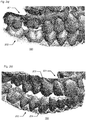
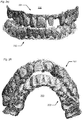
- Figure 2 shows examples of different bite configurations.
- Fig. 2a shows a bite configuration 200 where the patient's upper jaw 201 and lower jaw 202 are in static occlusion.
- Fig. 2b shows a bite configuration 200 where the canine 203 in the right side of the patient's upper jaw 201 is in contact with the canine 204 in the right side of the patient's lower jaw 202.
- Fig. 2c shows a bite configuration 200 where the incisal edge 205 of anterior teeth 206 in the upper jaw 201 is in contact with the incisal edge 207 of the anterior teeth 208 in the lower jaw 202.
- Fig. 2a shows a bite configuration 200 where the patient's upper jaw 201 and lower jaw 202 are in static occlusion.
- Fig. 2b shows a bite configuration 200 where the canine 203 in the right side of the patient's upper jaw 201 is in contact with the canine 204 in the right side of the patient's lower jaw 202.
- FIG. 2d shows a bite configuration 200 with a furthest protrusion and some laterotrusion of the jaws 201, 202.
- Fig. 2e shows a bite configuration 200 also with a furthest protrusion and some laterotrusion of the jaws 201, 202, but where the laterotrusion is different from fig. 2d ).
- Fig. 2f shows a bite configuration 200 with strong retrusion of the jaws 201, 202.
- Figure 3 shows schematically an embodiment where five 3D representations of different bite configurations 300, 301, 302, 303, 304 in respective occlusions have been obtained and the movement of the patient's jaws relative to each other is determined by interpolation between these.
- the movement determined in this embodiment is the natural chewing movement of the patient. Although a higher number of bite configurations will allow for the movement to be determined with higher accuracy to the natural movement it is possible to obtain it reasonably with as few as five bite configurations.
- the bite configuration where the maxilla 310 and the mandible 311 are in centric occlusion 300 is obtained. This is the natural bite of the patient. Typically, this is also the position where the teeth are in maximal occlusal contact.
- the sideward movement of the jaw when in occlusion can be determined by using the centric occlusion together with a left sideward bite configuration 302 wherein the mandible of the patient is moved to the left and a right sideward bite configuration 301 wherein the mandible of the patient is moved to the right.
- the sideward movement is then determined by interpolating between the right sideward bite configuration 301 and the central occlusion 300, and between the central occlusion 300 and the left sideward bite configuration 302.
- the interpolation may be linear; however, typically the movement of the dental arches defines a curved movement. Accordingly, the sideward movement may be determined by interpolating along a curved sideward line 305.
- the interpolation paths/curves 305, 308, 312 preferably define an average movement derived from typical jaw movements of patients.
- the system may check for occlusal contact between the teeth of the mandible and the maxilla. If the system finds that the teeth of the maxilla and mandible would overlap if moved along the sideward line then it open the jaws so that the teeth maintain contact but do no overlap. Similarly, if the system finds that there are no contacts between the teeth, e.g. the jaw is open, it would close the maxilla and the mandible together until contact occurs. This will be illustrated further in figures 4a- 4c and 5a - 5c .
- the opening and closing of the jaws may be a linear movement, however, it may also be a rotation around a default axis.
- the default axis can be set as default by the computer, set by the user or determined otherwise.
- the retrusion 307 which is the backwards movement from the centric occlusion to a back bite configuration 303 where the mandible is retracted can be determined by interpolating as described above along a retrusion curve 308.
- protrusion 309 which is the forward motion of the mandible relative to maxilla from the centric occlusion to a front bite configuration 304 can also be determined by interpolating as described along a protrusion curve 312.
- the determined occlusal movements may deviate from the interpolation lines. However, they will go through the respective points representing each 3D representation of a bite configuration since these are well known position. For improved accuracy further 3D representations of bite configurations may be obtained, which also has been mentioned earlier.
- Figure 4a show the 3D representation of a bite configuration where the 3D representation of the patient's upper jaw 310 and the 3D representation of the patient's lower jaw 311 are in centric occlusion 300.
- Fig. 4b shows the actual patient specific movement, where the lower jaw 311 is moved in a right lateral direction as indicated by the arrow.
- Figure 4b shows a configuration of the upper and lower jaw during lateral movement between the central occlusion and the right sideward bite configuration 301. The movement is done while keeping at least one contact point between the teeth of the upper and lower jaw.
- the contact points may not necessarily be present in the shown cross-section, but may occur between other teeth in the first 3D teeth model. However, in the current case a contact point 350 is present between two molars 337 and 327.
- Figures 4a, 4b and 4c shows representative relative positions of the upper and lower jaw during the actual patient specific movement. Other such sectioning views could be made in other areas at other points during the lateral movement or even during other movement, such as protrusion or retrusion.
- correction may be necessary when determining the patient specific movement, i.e. the occlusal contact movement, using interpolation.
- Figure 5a shows the bite configuration wherein the upper and lower jaw are in centric occlusion 300. This is identical to figure 4a as it was recorded in that position. However, when interpolating between the centric occlusion bite configuration and the right sideward bite configuration 301 an overlap 352 is detected between at the molars 327 and 337, as shown in figure 5b which corresponds to the position shown in figure 4b . Accordingly in order to compensate for this the jaws are moved apart until the overlapping area is gone, but only so far that an occlusal contact still exists.
- a trace surface 600 is generated by tracing the cusps of a tooth 601 of the first 3D teeth model as it follows the occlusal contact movement 602.
- the trace surface can then be used as a reference for designing the dental component.
- the trace surface 600 may be used as a cutting surface for cutting the dental component if it penetrates the trace surface and thus would block the actual patient specific occlusal contact movement to be performed by the patient.
- the trace surface is typically a sum of the trace lines or surfaces of each tooth in the respective jaws.
- a claim may refer to any of the preceding claims, and "any” is understood to mean “any one or more” of the preceding claims.
- the features of the method described above and in the following may be implemented in software and carried out on a data processing system or other processing means caused by the execution of computer-executable instructions.
- the instructions may be program code means loaded in a memory, such as a RAM, from a storage medium or from another computer via a computer network.
- the described features may be implemented by hardwired circuitry instead of software or in combination with software.
Landscapes
- Health & Medical Sciences (AREA)
- Life Sciences & Earth Sciences (AREA)
- General Health & Medical Sciences (AREA)
- Epidemiology (AREA)
- Dentistry (AREA)
- Animal Behavior & Ethology (AREA)
- Oral & Maxillofacial Surgery (AREA)
- Public Health (AREA)
- Veterinary Medicine (AREA)
- Engineering & Computer Science (AREA)
- Biomedical Technology (AREA)
- Biophysics (AREA)
- General Engineering & Computer Science (AREA)
- Dental Tools And Instruments Or Auxiliary Dental Instruments (AREA)
- Dental Prosthetics (AREA)
Claims (18)
- Verfahren zur Entwicklung einer dentalen Komponente (203, 204, 206, 208) in Form einer Zahnrestauration oder einer kieferorthopädischen Vorrichtung für einen Patienten, wobei das Verfahren umfasst:(i) Erhalten einer 3D-Darstellung des Oberkiefers (201) des Patienten;(ii) Erhalten einer 3D-Darstellung des Unterkiefers (202) des Patienten;(iii) Erhalten mindestens einer ersten 3D-Darstellung einer ersten Bissanordnung (200, 300, 301, 302, 303, 304) der Kiefer (201, 202) des Patienten in einer ersten Okklusion (300) und einer zweiten 3D-Darstellung einer zweiten Bissanordnung (200, 300, 301, 302, 303, 304) der Kiefer des Patienten in einer zweiten Okklusion (300), die sich von der ersten Okklusion unterscheidet;(iv) digitales Bestimmen einer okklusalen Kontaktbewegung (602) der Kiefer des Patienten relativ zueinander, basierend auf der mindestens ersten 3D-Darstellung, der zweiten 3D-Darstellung und dem Kontakt zwischen Ober- und Unterkiefer des Patienten;
wobei
digitales Bestimmen der okklusalen Kontaktbewegung (602) der Kiefer (201, 202) des Patienten relativ zueinander umfasst:- Interpolieren der Bewegung zwischen den gemessenen Bissanordnungen,- Erkennen von Überlappungsbereichen der Zähne der 3D-Darstellung des Oberkiefers (201) des Patienten und der 3D-Darstellung des Unterkiefers (202) des Patienten während der Interpolation und- Bewegen der 3D-Darstellung des Oberkiefers (201) des Patienten und der 3D-Darstellung des Unterkiefers (202) des Patienten auseinander, bis keine überlappenden Bereiche mehr erfasst werden; und(v) digitales Entwickeln der dentalen Komponente, basierend auf der okklusalen Kontaktbewegung der Kiefer des Patienten relativ zueinander. - Verfahren nach Anspruch 1, wobei das digitale Bestimmen der okklusalen Kontaktbewegung (602) eine aufeinanderfolgende Sequenz von mindestens zwei 3D-Darstellungen von Bissanordnungen (200, 300, 301, 302, 303, 304) der Kiefer (201, 202) des Patienten in jeweiligen Okklusionen umfasst.
- Verfahren nach Anspruch 2, wobei das Verfahren weiter das Erhalten der aufeinanderfolgenden Sequenz von mindestens zwei 3D-Darstellungen von Bissanordnungen (200, 300, 301, 302, 303, 304) der Kiefer (201, 202) des Patienten in jeweiligen Okklusionen unter Verwendung eines intraoralen Scanners umfasst.
- Verfahren nach Anspruch 2 oder 3, wobei das Verfahren weiter umfasst, dass die 3D-Darstellungen von Bissanordnungen (200, 300, 301, 302, 303, 304) als eine aufeinanderfolgende Sequenz von Bildern aufgezeichnet werden.
- Verfahren nach einem der Ansprüche 1 bis 4, wobei die Interpolation die Durchführung einer starren Transformation, einer linearen Transformation, einer nichtlinearen Transformation und/oder einer Kombination von linearen und nichtlinearen Transformationen umfasst.
- Verfahren nach Anspruch 5, wobei die Transformation Translation und Rotation umfasst.
- Verfahren nach Anspruch 1, 5 oder 6, wobei die Interpolation bezüglich der Zähne durchgeführt wird, die im Bereich der bekannten Datenpunkte von mindestens der ersten und der zweiten Bissanordnungen (200, 300, 301, 302, 303, 304) vorhanden sind.
- Verfahren nach einem der Ansprüche 1 bis 7, wobei das Verfahren weiter das Erhalten einer dritten 3D-Darstellung einer dritten Bissanordnung (200, 300, 301, 302, 303, 304) der Kiefer (201, 202) des Patienten umfasst.
- Verfahren nach einem der Ansprüche 1 bis 8, wobei das Verfahren das digitale Ausrichten mindestens der 3D-Darstellung des Oberkiefers (201), der 3D-Darstellung des Unterkiefers (202), der ersten 3D-Darstellung der ersten Bissanordnung und der zweiten 3D-Darstellung der zweiten Bissanordnung umfasst.
- Verfahren nach einem der Ansprüche 1 bis 9, wobei mindestens eine der 3D-Darstellungen Einschränkungen für die okklusale Kontaktbewegung (602) der Kiefer (201, 202) des Patienten vorsieht.
- Verfahren nach einem der Ansprüche 1 bis 10, wobei das Verfahren die Angabe umfasst, welche Bewegungen der Kiefer (201, 202) aufgrund von aufgezeichneten Bissanordnungen (200, 300, 301, 302, 303, 304) und welche Bewegungen der Kiefer aufgrund der bestimmten okklusalen Kontaktbewegung (602) erfolgen.
- Verfahren nach einem der Ansprüche 1 bis 11, wobei die okklusale Kontaktbewegung in der festgelegten Reihenfolge abgespielt wird.
- Verfahren nach einem der Ansprüche 1 bis 12, wobei die okklusale Kontaktbewegung eine Referenz definiert, die als Entwicklungsrichtlinie bei der Entwicklung der dentalen Komponente verwendet wird.
- Verfahren nach Anspruch 13, wobei die mindestens eine Kontaktfläche zwischen der dentalen Komponente und der Referenz vorgesehen ist.
- Verfahren nach Anspruch 13 oder 14, wobei die okklusale Kontaktbewegung eine Spurenoberfläche definiert, die als Entwicklungsrichtlinie bei der Entwicklung der dentalen Komponente dient.
- Verfahren nach Anspruch 15, bei dem die Spurenoberfläche als eine Schneidebene zum Trimmen der dentalen Komponente verwendet wird.
- Verfahren nach Anspruch 15, wobei mindestens ein Teil der dentalen Komponente auf der Spurenoberfläche eingerastet ist.
- System zum Ausführen des Verfahrens nach Anspruch 1 zur Entwicklung einer dentalen Komponente in Form einer Zahnrestauration oder einer kieferorthopädischen Vorrichtung für einen Patienten, wobei das System umfasst:- Mittel zum Erhalten einer 3D-Darstellung des Oberkiefers (201) des Patienten;- Mittel zum Erhalten einer 3D-Darstellung des Unterkiefers (202) des Patienten;- Mittel zum Erhalten mindestens einer ersten 3D-Darstellung einer ersten Bissanordnung (200, 300, 301, 302, 303, 304) der Kiefer (201, 202) des Patienten in einer ersten Okklusion und einer zweiten 3D-Darstellung einer zweiten Bissanordnung (200, 300, 301, 302, 303, 304) der Kiefer des Patienten in einer zweiten Okklusion, die sich von der ersten Okklusion unterscheidet;- Mittel zum digitalen Bestimmen einer okklusalen Kontaktbewegung (602) der Kiefer (201, 202) des Patienten relativ zueinander, basierend auf der mindestens ersten 3D-Darstellung, der zweiten 3D-Darstellung und dem Kontakt zwischen Ober- und Unterkiefer des Patienten; und- Mittel zum digitalen Bestimmen der okklusalen Kontaktbewegung der Kiefer (201, 202) des Patienten relativ zueinander umfasst Interpolieren der Bewegung zwischen den gemessenen Bissanordnungen,- Mittel zum Erkennen von Überlappungsbereichen der Zähne der 3D-Darstellung des Oberkiefers (201) des Patienten und der 3D-Darstellung des Unterkiefers (202) des Patienten während einer Interpolation,- Mittel zum Bewegen der 3D-Darstellung des Oberkiefers des Patienten und der 3D-Darstellung des Unterkiefers des Patienten, bis keine überlappenden Bereiche mehr erkannt werden; und- Mittel zum digitalen Entwickeln der dentalen Komponente, basierend auf der okklusalen Kontaktbewegung des Kiefers des Patienten relativ zueinander.
Priority Applications (2)
| Application Number | Priority Date | Filing Date | Title |
|---|---|---|---|
| EP18209776.6A EP3473207B1 (de) | 2012-10-18 | 2013-10-18 | System und verfahren zum entwerfen einer zahnkomponente |
| DK18209776.6T DK3473207T3 (da) | 2012-10-18 | 2013-10-18 | System og fremgangsmåde til udformning af en dental komponent |
Applications Claiming Priority (3)
| Application Number | Priority Date | Filing Date | Title |
|---|---|---|---|
| US201261715561P | 2012-10-18 | 2012-10-18 | |
| DKPA201270638 | 2012-10-18 | ||
| PCT/EP2013/071888 WO2014060595A1 (en) | 2012-10-18 | 2013-10-18 | Multiple bite configurations |
Related Child Applications (1)
| Application Number | Title | Priority Date | Filing Date |
|---|---|---|---|
| EP18209776.6A Division EP3473207B1 (de) | 2012-10-18 | 2013-10-18 | System und verfahren zum entwerfen einer zahnkomponente |
Publications (2)
| Publication Number | Publication Date |
|---|---|
| EP2908767A1 EP2908767A1 (de) | 2015-08-26 |
| EP2908767B1 true EP2908767B1 (de) | 2018-12-05 |
Family
ID=50487600
Family Applications (2)
| Application Number | Title | Priority Date | Filing Date |
|---|---|---|---|
| EP18209776.6A Active EP3473207B1 (de) | 2012-10-18 | 2013-10-18 | System und verfahren zum entwerfen einer zahnkomponente |
| EP13783288.7A Active EP2908767B1 (de) | 2012-10-18 | 2013-10-18 | System und verfahren zur entwicklung einer zahnkomponente |
Family Applications Before (1)
| Application Number | Title | Priority Date | Filing Date |
|---|---|---|---|
| EP18209776.6A Active EP3473207B1 (de) | 2012-10-18 | 2013-10-18 | System und verfahren zum entwerfen einer zahnkomponente |
Country Status (7)
| Country | Link |
|---|---|
| US (1) | US11000348B2 (de) |
| EP (2) | EP3473207B1 (de) |
| JP (1) | JP2015536163A (de) |
| CN (1) | CN104869940B (de) |
| DK (1) | DK3473207T3 (de) |
| ES (1) | ES2917382T3 (de) |
| WO (1) | WO2014060595A1 (de) |
Families Citing this family (23)
| Publication number | Priority date | Publication date | Assignee | Title |
|---|---|---|---|---|
| US20140372084A1 (en) * | 2011-11-15 | 2014-12-18 | Trispera Dental Inc. | Method and system for acquiring data from an individual for preparing a 3d model |
| US9737382B2 (en) | 2013-12-27 | 2017-08-22 | James R. Glidewell Dental Ceramics, Inc. | Apparatus and methods of making denture devices |
| US9707061B2 (en) | 2013-12-27 | 2017-07-18 | James R. Glidewell Dental Ceramics, Inc. | Apparatus and methods of making denture devices |
| US9844424B2 (en) * | 2014-02-21 | 2017-12-19 | Align Technology, Inc. | Dental appliance with repositioning jaw elements |
| US10537406B2 (en) | 2014-02-21 | 2020-01-21 | Align Technology, Inc. | Dental appliance with repositioning jaw elements |
| EP3107484B1 (de) | 2014-02-21 | 2022-03-30 | Trispera Dental Inc. | Zahnkonstruktionsverfahren und -system mit erweiterter realität |
| JP6596514B2 (ja) * | 2015-05-15 | 2019-10-23 | トロフィー | 咬合用歯科模型のx線走査のための方法及び装置 |
| CN109789330A (zh) * | 2016-03-30 | 2019-05-21 | P3竞技股份有限公司 | 气道和氧气提升咬嘴的增材打印 |
| US10304190B2 (en) * | 2016-06-29 | 2019-05-28 | 3M Innovative Properties Company | Virtual model of articulation from intra-oral scans |
| JP2018117837A (ja) * | 2017-01-25 | 2018-08-02 | 富士通株式会社 | 咬合状態特定コンピュータプログラム、咬合状態特定装置、及びその方法 |
| CN110475525A (zh) * | 2017-03-30 | 2019-11-19 | 株式会社Gc | 试戴义齿、试戴义齿制作程序及义齿制作方法 |
| WO2018222243A1 (en) | 2017-05-29 | 2018-12-06 | Chou Jang Ching | Aligning apparatus used in fabricating dental prostheses |
| DE102017217558A1 (de) * | 2017-10-02 | 2019-04-04 | Sirona Dental Systems Gmbh | Verfahren zur Herstellung einer geführten Aufbissschiene und eine geführte Aufbissschiene |
| CN108056829B (zh) * | 2017-10-19 | 2021-04-16 | 该美生物科技(上海)有限公司 | 一种用于促进牙齿重新定位牙科治疗的方法 |
| US11737857B2 (en) | 2017-11-01 | 2023-08-29 | Align Technology, Inc. | Systems and methods for correcting malocclusions of teeth |
| CN108836534A (zh) * | 2018-06-21 | 2018-11-20 | 四川大学 | 一种基于3d打印的前牙咬合阻断器的制作及使用方法 |
| US11654001B2 (en) * | 2018-10-04 | 2023-05-23 | Align Technology, Inc. | Molar trimming prediction and validation using machine learning |
| JP7170933B2 (ja) * | 2019-07-18 | 2022-11-14 | スリーエム イノベイティブ プロパティズ カンパニー | 歯科治療のための仮想咬合モデル |
| CN111973309B (zh) * | 2020-07-24 | 2022-05-17 | 上海交通大学医学院附属第九人民医院 | 一种调合导板制作方法 |
| CN113040953B (zh) * | 2021-04-28 | 2022-06-17 | 山东迈尔医疗科技有限公司 | 一种制作活动义齿支架的方法 |
| CN113362955B (zh) * | 2021-06-18 | 2023-09-29 | 北京联袂义齿技术有限公司 | 一种牙颌运动轨迹的建模及评价方法 |
| US11759296B2 (en) * | 2021-08-03 | 2023-09-19 | Ningbo Shenlai Medical Technology Co., Ltd. | Method for generating a digital data set representing a target tooth arrangement |
| WO2023213425A1 (en) * | 2022-05-06 | 2023-11-09 | 3Shape A/S | Method for monitoring changes in bite |
Family Cites Families (26)
| Publication number | Priority date | Publication date | Assignee | Title |
|---|---|---|---|---|
| US5340309A (en) * | 1990-09-06 | 1994-08-23 | Robertson James G | Apparatus and method for recording jaw motion |
| JP2000107203A (ja) | 1998-10-06 | 2000-04-18 | Shiyuukai | 歯科補綴物の製作方法 |
| US7160110B2 (en) * | 1999-11-30 | 2007-01-09 | Orametrix, Inc. | Three-dimensional occlusal and interproximal contact detection and display using virtual tooth models |
| EP2258303B1 (de) | 2000-04-19 | 2013-09-18 | OraMetrix, Inc. | System zur Erstellung eines individuellen virtuellen dreidimensionalen Modells eines Zahnes |
| US6582229B1 (en) | 2000-04-25 | 2003-06-24 | Align Technology, Inc. | Methods for modeling bite registration |
| US7084868B2 (en) * | 2000-04-26 | 2006-08-01 | University Of Louisville Research Foundation, Inc. | System and method for 3-D digital reconstruction of an oral cavity from a sequence of 2-D images |
| AU2003268686A1 (en) * | 2002-09-27 | 2004-04-19 | Nihon University | Occludator, face bow, occlusion-confirming system and tempromandibular joint-reproducing system |
| US7118375B2 (en) * | 2004-01-08 | 2006-10-10 | Duane Milford Durbin | Method and system for dental model occlusal determination using a replicate bite registration impression |
| ITMO20040050A1 (it) * | 2004-03-04 | 2004-06-04 | Marcello Marchesi | Metodo per la creazione e l'elaborazione di immagini per uso odontoiatrico |
| US20060003292A1 (en) * | 2004-05-24 | 2006-01-05 | Lauren Mark D | Digital manufacturing of removable oral appliances |
| US20080038684A1 (en) | 2005-01-27 | 2008-02-14 | Scott Keating | Systems and Processes for Computationally Setting Bite Alignment |
| US9504541B2 (en) | 2006-01-05 | 2016-11-29 | Dentsply International Inc. | Method and system for designing custom restorations for dental implants |
| US7698014B2 (en) * | 2006-01-20 | 2010-04-13 | 3M Innovative Properties Company | Local enforcement of accuracy in fabricated models |
| US20070207441A1 (en) * | 2006-03-03 | 2007-09-06 | Lauren Mark D | Four dimensional modeling of jaw and tooth dynamics |
| US8487962B2 (en) * | 2006-03-06 | 2013-07-16 | D4D Technologies, Llc | Augmented reality system for a dental laboratory |
| US7835811B2 (en) * | 2006-10-07 | 2010-11-16 | Voxelogix Corporation | Surgical guides and methods for positioning artificial teeth and dental implants |
| WO2008051130A1 (en) * | 2006-10-27 | 2008-05-02 | Nobel Biocare Services Ag | Method and apparatus for obtaining data for a dental component and a physical dental model |
| KR20100126700A (ko) * | 2008-01-23 | 2010-12-02 | 센서블 테크놀로지스, 인크. | 햅티컬 작동가능한 치아 모델링 시스템 |
| EP2229914B1 (de) | 2009-03-20 | 2018-05-30 | Nobel Biocare Services AG | System und Verfahren zur Ausrichtung virtuellen Modellen |
| JP2011000133A (ja) | 2009-06-16 | 2011-01-06 | Kazuo Okuma | 歯冠修復物製造に用いられる生態的機能コアの取得方法 |
| US8896592B2 (en) * | 2009-08-21 | 2014-11-25 | Align Technology, Inc. | Digital dental modeling |
| EP4059471A1 (de) * | 2010-02-25 | 2022-09-21 | 3Shape A/S | Dynamischer virtueller artikulator |
| US8352060B2 (en) * | 2010-05-05 | 2013-01-08 | Hankookin, LLC. | Computer-aided fabrication of a removable dental prosthesis |
| US8423166B2 (en) * | 2010-06-25 | 2013-04-16 | Kabushiki Kaisha Shofu | Method for calculating grinding portion of pre-grinding denture |
| JP5676325B2 (ja) | 2010-08-10 | 2015-02-25 | 伊藤 秀文 | 情報処理装置、情報処理方法、及びプログラム |
| WO2018070761A1 (ko) | 2016-10-11 | 2018-04-19 | 엘지전자 주식회사 | 냉매 유로 절환용 사방 밸브 |
-
2013
- 2013-10-18 EP EP18209776.6A patent/EP3473207B1/de active Active
- 2013-10-18 CN CN201380064771.0A patent/CN104869940B/zh active Active
- 2013-10-18 WO PCT/EP2013/071888 patent/WO2014060595A1/en active Application Filing
- 2013-10-18 DK DK18209776.6T patent/DK3473207T3/da active
- 2013-10-18 JP JP2015537279A patent/JP2015536163A/ja active Pending
- 2013-10-18 US US14/436,614 patent/US11000348B2/en active Active
- 2013-10-18 EP EP13783288.7A patent/EP2908767B1/de active Active
- 2013-10-18 ES ES18209776T patent/ES2917382T3/es active Active
Non-Patent Citations (1)
| Title |
|---|
| None * |
Also Published As
| Publication number | Publication date |
|---|---|
| ES2917382T3 (es) | 2022-07-08 |
| CN104869940A (zh) | 2015-08-26 |
| EP3473207B1 (de) | 2022-03-23 |
| EP3473207A1 (de) | 2019-04-24 |
| US11000348B2 (en) | 2021-05-11 |
| US20160166362A1 (en) | 2016-06-16 |
| JP2015536163A (ja) | 2015-12-21 |
| DK3473207T3 (da) | 2022-06-20 |
| WO2014060595A1 (en) | 2014-04-24 |
| EP2908767A1 (de) | 2015-08-26 |
| CN104869940B (zh) | 2017-11-07 |
Similar Documents
| Publication | Publication Date | Title |
|---|---|---|
| EP2908767B1 (de) | System und verfahren zur entwicklung einer zahnkomponente | |
| US11751981B2 (en) | Dynamic virtual articulator for simulating occlusion of teeth | |
| US11633265B2 (en) | Dynamic virtual articulator for simulating occlusion of teeth | |
| AU2013365985B2 (en) | Methods and systems for dental procedures | |
| US8706672B2 (en) | Computer-assisted creation of a custom tooth set-up using facial analysis | |
| US20150019176A1 (en) | Method and apparatus for dental articulation | |
| EP3188687B1 (de) | Verfahren zur verwendung einer digitalen repräsentation eines gesichtsbogens | |
| JP6871212B2 (ja) | 複数の噛み合わせ | |
| US20200268485A1 (en) | Method for determining and visualizing tooth movements and planned instances of tooth repositioning | |
| Edher | Virtual interocclusal registration using intra-oral scanning | |
| 권주현 | Measurement of mandibular kinematics for virtual articulation using a structured-light 3D scanner | |
| Lahori et al. | VIRTUAL ARTICULATORS: CHANGING TRENDS IN PROSTHODONTICS. |
Legal Events
| Date | Code | Title | Description |
|---|---|---|---|
| PUAI | Public reference made under article 153(3) epc to a published international application that has entered the european phase |
Free format text: ORIGINAL CODE: 0009012 |
|
| 17P | Request for examination filed |
Effective date: 20150513 |
|
| AK | Designated contracting states |
Kind code of ref document: A1 Designated state(s): AL AT BE BG CH CY CZ DE DK EE ES FI FR GB GR HR HU IE IS IT LI LT LU LV MC MK MT NL NO PL PT RO RS SE SI SK SM TR |
|
| AX | Request for extension of the european patent |
Extension state: BA ME |
|
| DAX | Request for extension of the european patent (deleted) | ||
| STAA | Information on the status of an ep patent application or granted ep patent |
Free format text: STATUS: EXAMINATION IS IN PROGRESS |
|
| 17Q | First examination report despatched |
Effective date: 20170410 |
|
| GRAP | Despatch of communication of intention to grant a patent |
Free format text: ORIGINAL CODE: EPIDOSNIGR1 |
|
| STAA | Information on the status of an ep patent application or granted ep patent |
Free format text: STATUS: GRANT OF PATENT IS INTENDED |
|
| INTG | Intention to grant announced |
Effective date: 20180301 |
|
| GRAJ | Information related to disapproval of communication of intention to grant by the applicant or resumption of examination proceedings by the epo deleted |
Free format text: ORIGINAL CODE: EPIDOSDIGR1 |
|
| STAA | Information on the status of an ep patent application or granted ep patent |
Free format text: STATUS: EXAMINATION IS IN PROGRESS |
|
| GRAP | Despatch of communication of intention to grant a patent |
Free format text: ORIGINAL CODE: EPIDOSNIGR1 |
|
| STAA | Information on the status of an ep patent application or granted ep patent |
Free format text: STATUS: GRANT OF PATENT IS INTENDED |
|
| INTC | Intention to grant announced (deleted) | ||
| INTG | Intention to grant announced |
Effective date: 20180801 |
|
| GRAS | Grant fee paid |
Free format text: ORIGINAL CODE: EPIDOSNIGR3 |
|
| GRAA | (expected) grant |
Free format text: ORIGINAL CODE: 0009210 |
|
| STAA | Information on the status of an ep patent application or granted ep patent |
Free format text: STATUS: THE PATENT HAS BEEN GRANTED |
|
| AK | Designated contracting states |
Kind code of ref document: B1 Designated state(s): AL AT BE BG CH CY CZ DE DK EE ES FI FR GB GR HR HU IE IS IT LI LT LU LV MC MK MT NL NO PL PT RO RS SE SI SK SM TR |
|
| REG | Reference to a national code |
Ref country code: GB Ref legal event code: FG4D |
|
| REG | Reference to a national code |
Ref country code: CH Ref legal event code: EP |
|
| REG | Reference to a national code |
Ref country code: AT Ref legal event code: REF Ref document number: 1072111 Country of ref document: AT Kind code of ref document: T Effective date: 20181215 |
|
| REG | Reference to a national code |
Ref country code: IE Ref legal event code: FG4D |
|
| REG | Reference to a national code |
Ref country code: DE Ref legal event code: R096 Ref document number: 602013047856 Country of ref document: DE |
|
| REG | Reference to a national code |
Ref country code: CH Ref legal event code: NV Representative=s name: VALIPAT S.A. GEVERS SA, CH |
|
| REG | Reference to a national code |
Ref country code: DK Ref legal event code: T3 Effective date: 20190318 |
|
| REG | Reference to a national code |
Ref country code: CH Ref legal event code: PCAR Free format text: NEW ADDRESS: RUE DES NOYERS 11, 2000 NEUCHATEL (CH) |
|
| REG | Reference to a national code |
Ref country code: SE Ref legal event code: TRGR |
|
| REG | Reference to a national code |
Ref country code: NL Ref legal event code: FP |
|
| REG | Reference to a national code |
Ref country code: AT Ref legal event code: MK05 Ref document number: 1072111 Country of ref document: AT Kind code of ref document: T Effective date: 20181205 |
|
| REG | Reference to a national code |
Ref country code: LT Ref legal event code: MG4D |
|
| PG25 | Lapsed in a contracting state [announced via postgrant information from national office to epo] |
Ref country code: NO Free format text: LAPSE BECAUSE OF FAILURE TO SUBMIT A TRANSLATION OF THE DESCRIPTION OR TO PAY THE FEE WITHIN THE PRESCRIBED TIME-LIMIT Effective date: 20190305 Ref country code: BG Free format text: LAPSE BECAUSE OF FAILURE TO SUBMIT A TRANSLATION OF THE DESCRIPTION OR TO PAY THE FEE WITHIN THE PRESCRIBED TIME-LIMIT Effective date: 20190305 Ref country code: HR Free format text: LAPSE BECAUSE OF FAILURE TO SUBMIT A TRANSLATION OF THE DESCRIPTION OR TO PAY THE FEE WITHIN THE PRESCRIBED TIME-LIMIT Effective date: 20181205 Ref country code: AT Free format text: LAPSE BECAUSE OF FAILURE TO SUBMIT A TRANSLATION OF THE DESCRIPTION OR TO PAY THE FEE WITHIN THE PRESCRIBED TIME-LIMIT Effective date: 20181205 Ref country code: LT Free format text: LAPSE BECAUSE OF FAILURE TO SUBMIT A TRANSLATION OF THE DESCRIPTION OR TO PAY THE FEE WITHIN THE PRESCRIBED TIME-LIMIT Effective date: 20181205 Ref country code: LV Free format text: LAPSE BECAUSE OF FAILURE TO SUBMIT A TRANSLATION OF THE DESCRIPTION OR TO PAY THE FEE WITHIN THE PRESCRIBED TIME-LIMIT Effective date: 20181205 Ref country code: FI Free format text: LAPSE BECAUSE OF FAILURE TO SUBMIT A TRANSLATION OF THE DESCRIPTION OR TO PAY THE FEE WITHIN THE PRESCRIBED TIME-LIMIT Effective date: 20181205 |
|
| REG | Reference to a national code |
Ref country code: ES Ref legal event code: FG2A Ref document number: 2713550 Country of ref document: ES Kind code of ref document: T3 Effective date: 20190522 |
|
| PG25 | Lapsed in a contracting state [announced via postgrant information from national office to epo] |
Ref country code: AL Free format text: LAPSE BECAUSE OF FAILURE TO SUBMIT A TRANSLATION OF THE DESCRIPTION OR TO PAY THE FEE WITHIN THE PRESCRIBED TIME-LIMIT Effective date: 20181205 Ref country code: RS Free format text: LAPSE BECAUSE OF FAILURE TO SUBMIT A TRANSLATION OF THE DESCRIPTION OR TO PAY THE FEE WITHIN THE PRESCRIBED TIME-LIMIT Effective date: 20181205 Ref country code: GR Free format text: LAPSE BECAUSE OF FAILURE TO SUBMIT A TRANSLATION OF THE DESCRIPTION OR TO PAY THE FEE WITHIN THE PRESCRIBED TIME-LIMIT Effective date: 20190306 |
|
| PG25 | Lapsed in a contracting state [announced via postgrant information from national office to epo] |
Ref country code: PL Free format text: LAPSE BECAUSE OF FAILURE TO SUBMIT A TRANSLATION OF THE DESCRIPTION OR TO PAY THE FEE WITHIN THE PRESCRIBED TIME-LIMIT Effective date: 20181205 Ref country code: PT Free format text: LAPSE BECAUSE OF FAILURE TO SUBMIT A TRANSLATION OF THE DESCRIPTION OR TO PAY THE FEE WITHIN THE PRESCRIBED TIME-LIMIT Effective date: 20190405 Ref country code: CZ Free format text: LAPSE BECAUSE OF FAILURE TO SUBMIT A TRANSLATION OF THE DESCRIPTION OR TO PAY THE FEE WITHIN THE PRESCRIBED TIME-LIMIT Effective date: 20181205 |
|
| PG25 | Lapsed in a contracting state [announced via postgrant information from national office to epo] |
Ref country code: IS Free format text: LAPSE BECAUSE OF FAILURE TO SUBMIT A TRANSLATION OF THE DESCRIPTION OR TO PAY THE FEE WITHIN THE PRESCRIBED TIME-LIMIT Effective date: 20190405 Ref country code: SM Free format text: LAPSE BECAUSE OF FAILURE TO SUBMIT A TRANSLATION OF THE DESCRIPTION OR TO PAY THE FEE WITHIN THE PRESCRIBED TIME-LIMIT Effective date: 20181205 Ref country code: RO Free format text: LAPSE BECAUSE OF FAILURE TO SUBMIT A TRANSLATION OF THE DESCRIPTION OR TO PAY THE FEE WITHIN THE PRESCRIBED TIME-LIMIT Effective date: 20181205 Ref country code: SK Free format text: LAPSE BECAUSE OF FAILURE TO SUBMIT A TRANSLATION OF THE DESCRIPTION OR TO PAY THE FEE WITHIN THE PRESCRIBED TIME-LIMIT Effective date: 20181205 Ref country code: EE Free format text: LAPSE BECAUSE OF FAILURE TO SUBMIT A TRANSLATION OF THE DESCRIPTION OR TO PAY THE FEE WITHIN THE PRESCRIBED TIME-LIMIT Effective date: 20181205 |
|
| REG | Reference to a national code |
Ref country code: DE Ref legal event code: R097 Ref document number: 602013047856 Country of ref document: DE |
|
| PLBE | No opposition filed within time limit |
Free format text: ORIGINAL CODE: 0009261 |
|
| STAA | Information on the status of an ep patent application or granted ep patent |
Free format text: STATUS: NO OPPOSITION FILED WITHIN TIME LIMIT |
|
| PG25 | Lapsed in a contracting state [announced via postgrant information from national office to epo] |
Ref country code: SI Free format text: LAPSE BECAUSE OF FAILURE TO SUBMIT A TRANSLATION OF THE DESCRIPTION OR TO PAY THE FEE WITHIN THE PRESCRIBED TIME-LIMIT Effective date: 20181205 |
|
| 26N | No opposition filed |
Effective date: 20190906 |
|
| PG25 | Lapsed in a contracting state [announced via postgrant information from national office to epo] |
Ref country code: TR Free format text: LAPSE BECAUSE OF FAILURE TO SUBMIT A TRANSLATION OF THE DESCRIPTION OR TO PAY THE FEE WITHIN THE PRESCRIBED TIME-LIMIT Effective date: 20181205 |
|
| PG25 | Lapsed in a contracting state [announced via postgrant information from national office to epo] |
Ref country code: MC Free format text: LAPSE BECAUSE OF FAILURE TO SUBMIT A TRANSLATION OF THE DESCRIPTION OR TO PAY THE FEE WITHIN THE PRESCRIBED TIME-LIMIT Effective date: 20181205 |
|
| PG25 | Lapsed in a contracting state [announced via postgrant information from national office to epo] |
Ref country code: LU Free format text: LAPSE BECAUSE OF NON-PAYMENT OF DUE FEES Effective date: 20191018 |
|
| REG | Reference to a national code |
Ref country code: BE Ref legal event code: MM Effective date: 20191031 |
|
| PG25 | Lapsed in a contracting state [announced via postgrant information from national office to epo] |
Ref country code: BE Free format text: LAPSE BECAUSE OF NON-PAYMENT OF DUE FEES Effective date: 20191031 |
|
| PG25 | Lapsed in a contracting state [announced via postgrant information from national office to epo] |
Ref country code: IE Free format text: LAPSE BECAUSE OF NON-PAYMENT OF DUE FEES Effective date: 20191018 |
|
| PG25 | Lapsed in a contracting state [announced via postgrant information from national office to epo] |
Ref country code: CY Free format text: LAPSE BECAUSE OF FAILURE TO SUBMIT A TRANSLATION OF THE DESCRIPTION OR TO PAY THE FEE WITHIN THE PRESCRIBED TIME-LIMIT Effective date: 20181205 |
|
| PG25 | Lapsed in a contracting state [announced via postgrant information from national office to epo] |
Ref country code: MT Free format text: LAPSE BECAUSE OF FAILURE TO SUBMIT A TRANSLATION OF THE DESCRIPTION OR TO PAY THE FEE WITHIN THE PRESCRIBED TIME-LIMIT Effective date: 20181205 Ref country code: HU Free format text: LAPSE BECAUSE OF FAILURE TO SUBMIT A TRANSLATION OF THE DESCRIPTION OR TO PAY THE FEE WITHIN THE PRESCRIBED TIME-LIMIT; INVALID AB INITIO Effective date: 20131018 |
|
| PG25 | Lapsed in a contracting state [announced via postgrant information from national office to epo] |
Ref country code: MK Free format text: LAPSE BECAUSE OF FAILURE TO SUBMIT A TRANSLATION OF THE DESCRIPTION OR TO PAY THE FEE WITHIN THE PRESCRIBED TIME-LIMIT Effective date: 20181205 |
|
| PGFP | Annual fee paid to national office [announced via postgrant information from national office to epo] |
Ref country code: NL Payment date: 20221019 Year of fee payment: 10 |
|
| PGFP | Annual fee paid to national office [announced via postgrant information from national office to epo] |
Ref country code: SE Payment date: 20221019 Year of fee payment: 10 Ref country code: DK Payment date: 20221021 Year of fee payment: 10 |
|
| PGFP | Annual fee paid to national office [announced via postgrant information from national office to epo] |
Ref country code: CH Payment date: 20221026 Year of fee payment: 10 |
|
| P01 | Opt-out of the competence of the unified patent court (upc) registered |
Effective date: 20230529 |
|
| PGFP | Annual fee paid to national office [announced via postgrant information from national office to epo] |
Ref country code: GB Payment date: 20231020 Year of fee payment: 11 |
|
| PGFP | Annual fee paid to national office [announced via postgrant information from national office to epo] |
Ref country code: ES Payment date: 20231227 Year of fee payment: 11 |
|
| PGFP | Annual fee paid to national office [announced via postgrant information from national office to epo] |
Ref country code: IT Payment date: 20231026 Year of fee payment: 11 Ref country code: FR Payment date: 20231025 Year of fee payment: 11 Ref country code: DE Payment date: 20231020 Year of fee payment: 11 |