EP2908111A1 - Instrumentation equipment for nuclear power plant - Google Patents
Instrumentation equipment for nuclear power plant Download PDFInfo
- Publication number
- EP2908111A1 EP2908111A1 EP15154576.1A EP15154576A EP2908111A1 EP 2908111 A1 EP2908111 A1 EP 2908111A1 EP 15154576 A EP15154576 A EP 15154576A EP 2908111 A1 EP2908111 A1 EP 2908111A1
- Authority
- EP
- European Patent Office
- Prior art keywords
- pressure
- power plant
- nuclear power
- hydrogen
- storage material
- Prior art date
- Legal status (The legal status is an assumption and is not a legal conclusion. Google has not performed a legal analysis and makes no representation as to the accuracy of the status listed.)
- Withdrawn
Links
- UFHFLCQGNIYNRP-UHFFFAOYSA-N Hydrogen Chemical compound [H][H] UFHFLCQGNIYNRP-UHFFFAOYSA-N 0.000 claims abstract description 157
- 239000001257 hydrogen Substances 0.000 claims abstract description 153
- 229910052739 hydrogen Inorganic materials 0.000 claims abstract description 153
- 239000011232 storage material Substances 0.000 claims abstract description 100
- 239000007788 liquid Substances 0.000 claims abstract description 89
- 239000012530 fluid Substances 0.000 claims abstract description 57
- 239000010410 layer Substances 0.000 claims description 43
- 229920002545 silicone oil Polymers 0.000 claims description 38
- 229920003216 poly(methylphenylsiloxane) Polymers 0.000 claims description 33
- 125000004435 hydrogen atom Chemical group [H]* 0.000 claims description 24
- 229930195733 hydrocarbon Natural products 0.000 claims description 21
- 150000002430 hydrocarbons Chemical class 0.000 claims description 21
- KDLHZDBZIXYQEI-UHFFFAOYSA-N Palladium Chemical compound [Pd] KDLHZDBZIXYQEI-UHFFFAOYSA-N 0.000 claims description 14
- 125000001997 phenyl group Chemical group [H]C1=C([H])C([H])=C(*)C([H])=C1[H] 0.000 claims description 12
- 229910045601 alloy Inorganic materials 0.000 claims description 7
- 239000000956 alloy Substances 0.000 claims description 7
- 239000000463 material Substances 0.000 claims description 7
- 229910052763 palladium Inorganic materials 0.000 claims description 6
- 239000004215 Carbon black (E152) Substances 0.000 claims description 5
- PXHVJJICTQNCMI-UHFFFAOYSA-N Nickel Chemical compound [Ni] PXHVJJICTQNCMI-UHFFFAOYSA-N 0.000 claims description 4
- RTAQQCXQSZGOHL-UHFFFAOYSA-N Titanium Chemical compound [Ti] RTAQQCXQSZGOHL-UHFFFAOYSA-N 0.000 claims description 4
- 230000000903 blocking effect Effects 0.000 claims description 4
- BASFCYQUMIYNBI-UHFFFAOYSA-N platinum Chemical compound [Pt] BASFCYQUMIYNBI-UHFFFAOYSA-N 0.000 claims description 4
- 239000002344 surface layer Substances 0.000 claims description 4
- 229910052719 titanium Inorganic materials 0.000 claims description 4
- 239000010936 titanium Substances 0.000 claims description 4
- 229910017052 cobalt Inorganic materials 0.000 claims description 3
- 239000010941 cobalt Substances 0.000 claims description 3
- GUTLYIVDDKVIGB-UHFFFAOYSA-N cobalt atom Chemical compound [Co] GUTLYIVDDKVIGB-UHFFFAOYSA-N 0.000 claims description 3
- OYPRJOBELJOOCE-UHFFFAOYSA-N Calcium Chemical compound [Ca] OYPRJOBELJOOCE-UHFFFAOYSA-N 0.000 claims description 2
- VYZAMTAEIAYCRO-UHFFFAOYSA-N Chromium Chemical compound [Cr] VYZAMTAEIAYCRO-UHFFFAOYSA-N 0.000 claims description 2
- RYGMFSIKBFXOCR-UHFFFAOYSA-N Copper Chemical compound [Cu] RYGMFSIKBFXOCR-UHFFFAOYSA-N 0.000 claims description 2
- FYYHWMGAXLPEAU-UHFFFAOYSA-N Magnesium Chemical compound [Mg] FYYHWMGAXLPEAU-UHFFFAOYSA-N 0.000 claims description 2
- BQCADISMDOOEFD-UHFFFAOYSA-N Silver Chemical compound [Ag] BQCADISMDOOEFD-UHFFFAOYSA-N 0.000 claims description 2
- QCWXUUIWCKQGHC-UHFFFAOYSA-N Zirconium Chemical compound [Zr] QCWXUUIWCKQGHC-UHFFFAOYSA-N 0.000 claims description 2
- 229910052782 aluminium Inorganic materials 0.000 claims description 2
- XAGFODPZIPBFFR-UHFFFAOYSA-N aluminium Chemical compound [Al] XAGFODPZIPBFFR-UHFFFAOYSA-N 0.000 claims description 2
- 229910052791 calcium Inorganic materials 0.000 claims description 2
- 239000011575 calcium Substances 0.000 claims description 2
- 229910052804 chromium Inorganic materials 0.000 claims description 2
- 239000011651 chromium Substances 0.000 claims description 2
- 229910052802 copper Inorganic materials 0.000 claims description 2
- 239000010949 copper Substances 0.000 claims description 2
- PCHJSUWPFVWCPO-UHFFFAOYSA-N gold Chemical compound [Au] PCHJSUWPFVWCPO-UHFFFAOYSA-N 0.000 claims description 2
- 229910052737 gold Inorganic materials 0.000 claims description 2
- 239000010931 gold Substances 0.000 claims description 2
- 229910052749 magnesium Inorganic materials 0.000 claims description 2
- 239000011777 magnesium Substances 0.000 claims description 2
- WPBNNNQJVZRUHP-UHFFFAOYSA-L manganese(2+);methyl n-[[2-(methoxycarbonylcarbamothioylamino)phenyl]carbamothioyl]carbamate;n-[2-(sulfidocarbothioylamino)ethyl]carbamodithioate Chemical compound [Mn+2].[S-]C(=S)NCCNC([S-])=S.COC(=O)NC(=S)NC1=CC=CC=C1NC(=S)NC(=O)OC WPBNNNQJVZRUHP-UHFFFAOYSA-L 0.000 claims description 2
- 229910052759 nickel Inorganic materials 0.000 claims description 2
- 229910052758 niobium Inorganic materials 0.000 claims description 2
- 239000010955 niobium Substances 0.000 claims description 2
- GUCVJGMIXFAOAE-UHFFFAOYSA-N niobium atom Chemical compound [Nb] GUCVJGMIXFAOAE-UHFFFAOYSA-N 0.000 claims description 2
- 229910052697 platinum Inorganic materials 0.000 claims description 2
- 229910052709 silver Inorganic materials 0.000 claims description 2
- 239000004332 silver Substances 0.000 claims description 2
- 229910052720 vanadium Inorganic materials 0.000 claims description 2
- LEONUFNNVUYDNQ-UHFFFAOYSA-N vanadium atom Chemical compound [V] LEONUFNNVUYDNQ-UHFFFAOYSA-N 0.000 claims description 2
- 229910052726 zirconium Inorganic materials 0.000 claims description 2
- 230000015572 biosynthetic process Effects 0.000 abstract description 11
- VNWKTOKETHGBQD-UHFFFAOYSA-N methane Chemical compound C VNWKTOKETHGBQD-UHFFFAOYSA-N 0.000 description 50
- XLYOFNOQVPJJNP-UHFFFAOYSA-N water Substances O XLYOFNOQVPJJNP-UHFFFAOYSA-N 0.000 description 28
- 238000010586 diagram Methods 0.000 description 27
- 238000005259 measurement Methods 0.000 description 26
- ATUOYWHBWRKTHZ-UHFFFAOYSA-N Propane Chemical compound CCC ATUOYWHBWRKTHZ-UHFFFAOYSA-N 0.000 description 22
- 125000000118 dimethyl group Chemical group [H]C([H])([H])* 0.000 description 20
- 230000000694 effects Effects 0.000 description 18
- 238000000034 method Methods 0.000 description 17
- 230000005855 radiation Effects 0.000 description 17
- 230000005251 gamma ray Effects 0.000 description 16
- 125000002496 methyl group Chemical group [H]C([H])([H])* 0.000 description 16
- OTMSDBZUPAUEDD-UHFFFAOYSA-N Ethane Chemical compound CC OTMSDBZUPAUEDD-UHFFFAOYSA-N 0.000 description 11
- 239000001294 propane Substances 0.000 description 11
- 238000012360 testing method Methods 0.000 description 10
- 238000003608 radiolysis reaction Methods 0.000 description 9
- 239000007789 gas Substances 0.000 description 8
- 238000000354 decomposition reaction Methods 0.000 description 7
- UHOVQNZJYSORNB-UHFFFAOYSA-N Benzene Chemical compound C1=CC=CC=C1 UHOVQNZJYSORNB-UHFFFAOYSA-N 0.000 description 6
- 230000001186 cumulative effect Effects 0.000 description 6
- 239000010408 film Substances 0.000 description 5
- 238000000926 separation method Methods 0.000 description 5
- 238000009530 blood pressure measurement Methods 0.000 description 4
- 239000001273 butane Substances 0.000 description 4
- IJDNQMDRQITEOD-UHFFFAOYSA-N n-butane Chemical compound CCCC IJDNQMDRQITEOD-UHFFFAOYSA-N 0.000 description 4
- OFBQJSOFQDEBGM-UHFFFAOYSA-N n-pentane Natural products CCCCC OFBQJSOFQDEBGM-UHFFFAOYSA-N 0.000 description 4
- 239000012466 permeate Substances 0.000 description 4
- 238000011144 upstream manufacturing Methods 0.000 description 4
- 238000004817 gas chromatography Methods 0.000 description 3
- 150000002431 hydrogen Chemical class 0.000 description 3
- 239000002245 particle Substances 0.000 description 3
- 239000000843 powder Substances 0.000 description 3
- 230000002195 synergetic effect Effects 0.000 description 3
- 239000010409 thin film Substances 0.000 description 3
- 229910018540 Si C Inorganic materials 0.000 description 2
- 238000009825 accumulation Methods 0.000 description 2
- 238000004458 analytical method Methods 0.000 description 2
- 238000009835 boiling Methods 0.000 description 2
- 229910052799 carbon Inorganic materials 0.000 description 2
- 125000004432 carbon atom Chemical group C* 0.000 description 2
- 238000009833 condensation Methods 0.000 description 2
- 230000005494 condensation Effects 0.000 description 2
- 230000006378 damage Effects 0.000 description 2
- 230000006866 deterioration Effects 0.000 description 2
- 230000007774 longterm Effects 0.000 description 2
- 238000012423 maintenance Methods 0.000 description 2
- 238000007747 plating Methods 0.000 description 2
- 239000000047 product Substances 0.000 description 2
- 238000000197 pyrolysis Methods 0.000 description 2
- 229920006395 saturated elastomer Polymers 0.000 description 2
- 239000004065 semiconductor Substances 0.000 description 2
- 229910010271 silicon carbide Inorganic materials 0.000 description 2
- 239000007787 solid Substances 0.000 description 2
- 238000004544 sputter deposition Methods 0.000 description 2
- 239000010935 stainless steel Substances 0.000 description 2
- 229910001220 stainless steel Inorganic materials 0.000 description 2
- 238000007796 conventional method Methods 0.000 description 1
- 238000001816 cooling Methods 0.000 description 1
- 239000000498 cooling water Substances 0.000 description 1
- 230000007423 decrease Effects 0.000 description 1
- 238000012217 deletion Methods 0.000 description 1
- 230000037430 deletion Effects 0.000 description 1
- 230000005484 gravity Effects 0.000 description 1
- -1 hydrogen ions Chemical class 0.000 description 1
- 230000010354 integration Effects 0.000 description 1
- 230000001678 irradiating effect Effects 0.000 description 1
- 229910052751 metal Inorganic materials 0.000 description 1
- 239000002184 metal Substances 0.000 description 1
- 238000002156 mixing Methods 0.000 description 1
- 239000003758 nuclear fuel Substances 0.000 description 1
- 238000005504 petroleum refining Methods 0.000 description 1
- 239000011148 porous material Substances 0.000 description 1
- 238000005096 rolling process Methods 0.000 description 1
- 229910052710 silicon Inorganic materials 0.000 description 1
- 239000010703 silicon Substances 0.000 description 1
- 239000000126 substance Substances 0.000 description 1
Images


Classifications
-
- G—PHYSICS
- G21—NUCLEAR PHYSICS; NUCLEAR ENGINEERING
- G21D—NUCLEAR POWER PLANT
- G21D3/00—Control of nuclear power plant
- G21D3/08—Regulation of any parameters in the plant
-
- G—PHYSICS
- G01—MEASURING; TESTING
- G01L—MEASURING FORCE, STRESS, TORQUE, WORK, MECHANICAL POWER, MECHANICAL EFFICIENCY, OR FLUID PRESSURE
- G01L19/00—Details of, or accessories for, apparatus for measuring steady or quasi-steady pressure of a fluent medium insofar as such details or accessories are not special to particular types of pressure gauges
- G01L19/06—Means for preventing overload or deleterious influence of the measured medium on the measuring device or vice versa
- G01L19/0627—Protection against aggressive medium in general
-
- G—PHYSICS
- G21—NUCLEAR PHYSICS; NUCLEAR ENGINEERING
- G21C—NUCLEAR REACTORS
- G21C17/00—Monitoring; Testing ; Maintaining
-
- Y—GENERAL TAGGING OF NEW TECHNOLOGICAL DEVELOPMENTS; GENERAL TAGGING OF CROSS-SECTIONAL TECHNOLOGIES SPANNING OVER SEVERAL SECTIONS OF THE IPC; TECHNICAL SUBJECTS COVERED BY FORMER USPC CROSS-REFERENCE ART COLLECTIONS [XRACs] AND DIGESTS
- Y02—TECHNOLOGIES OR APPLICATIONS FOR MITIGATION OR ADAPTATION AGAINST CLIMATE CHANGE
- Y02E—REDUCTION OF GREENHOUSE GAS [GHG] EMISSIONS, RELATED TO ENERGY GENERATION, TRANSMISSION OR DISTRIBUTION
- Y02E30/00—Energy generation of nuclear origin
- Y02E30/30—Nuclear fission reactors
Definitions
- the present invention relates to instrumentation equipment for a nuclear power plant, in particular instrumentation equipment for a nuclear power plant having a pressure transmitter suitable for using in a radiation environment and high-temperature environment.
- a pressure transmitter In instrumentation equipment for a nuclear power plant, a pressure transmitter is utilized in order to measure the quantity of process (water level, pressure, differential pressure and flow rate).
- a pressure transmitter transfers a pressure of fluid received by a diaphragm to a pressure sensor with a sealed liquid filled within an impulse line, and transmits the electrical signal detected by the pressure sensor outside.
- a pressure transmitter which measures absolute pressure and one which measures differential pressure or gauge pressure.
- pressure transmitters are used for various measurement of a process fluid in a nuclear power plant, as well as a petroleum-refining plant, a chemical plant, etc., and for example, a precision of ⁇ 1% is required in view of ensuring the safety of a plant and the quality of a product.
- a part of hydrogen (hydrogen atoms, hydrogen molecules and hydrogen ions) contained in a process fluid permeates the diaphragm and remain in the impulse line as bubbles. This increases the pressure within the impulse line to result in the deterioration of pressure-transmission properties, and therefore it was difficult to keep the measurement precision.
- JP-A-2005-114453 discloses that a hydrogen storage alloy film is formed on one side surface of the diaphragm contacting on the sealed liquid to capture hydrogen which has permeated the diaphragm on the hydrogen storage alloy film, and also reports that according to this technique, the formation of bubbles in the sealed liquid can be inhibited to maintain the pressure-transmission properties.
- the above-described conventional technique is for reducing the effect of hydrogen which has permeated the diaphragm from the outside of a pressure transmitter, and the technique did not take into account hydrogen generated within the impulse line of the pressure transmitter and hydrogen which has permeated the diaphragm into the inside of the impulse line. That is, under a special environment such as a radiation environment or a high-temperature environment, the sealed liquid filled within the impulse line of the pressure transmitter decomposes due to radiation or heat to generate a gas such as hydrogen and hydrocarbons. This also deteriorates the pressure-transmission properties of the pressure transmitter because the generated gas becomes bubbles when exceeding the solubility of the sealed liquid.
- the object of the present invention is to provide instrumentation equipment for a nuclear power plant in which the formation of bubbles in the impulse line can be surely inhibited and thereby reliability and maintainability are improved over a long duration.
- the instrumentation equipment for a nuclear power plant of the present invention includes a tubular impulse line provided on a site to measure a fluid to be measured in a primary system of the nuclear power plant, a sealed liquid filled within the impulse line, a pressure-sensing diaphragm to receive a pressure of the fluid to be measured, the pressure-sensing diaphragm provided in a state of closing one opening of the impulse line, a pressure sensor provided on another opening of the impulse line in a state of being exposed to the sealed liquid, and a hydrogen storage material provided within the impulse line.
- the instrumentation equipment for the nuclear power plant of the present invention with the above-described configuration has the hydrogen storage material within the impulse line.
- hydrogen generated due to the decomposition of the sealed liquid is stored in the hydrogen storage material, and therefore the formation of bubbles in the impulse line can be inhibited and the pressure in the differential pressure line can be stabilized.
- the quantity of process can be measured within a given precision over a long duration, leading to a reduction of maintenance costs. That is, reliability and maintainability can be improved.
- FIG. 12 is a diagram illustrating the configuration of a pressure transmitter, which is the principal part of the instrumentation equipment for the nuclear power plant according to a fourth embodiment.
- FIG. 1 is a diagram illustrating an application example of the instrumentation equipment for a nuclear power plant according to the first embodiment intended for a nuclear power plant primary system and the configuration of a feedwater system and condensation system in a nuclear power plant of boiling water reactor (BWR) type.
- BWR boiling water reactor
- the nuclear power plant 100 has a pressure vessel 53 containing a reactor core 51, which is a bunch of nuclear fuels, soaked in reactor water 52.
- the pressure vessel 53 is connected to a high-pressure turbine 55 via a main steam piping 54, and the high-pressure turbine 55 is connected to a low-pressure turbine 57 via a moisture separation heater 56.
- the high-pressure turbine 55 and the low-pressure turbine 57 are disposed coaxially and further connected to a power generator 58 operated with these turbines.
- the moisture separation heater 56 is provided with a drain tank 60 via a drain piping 59.
- the low-pressure turbine 57 is further provided with a condenser 61, and the cooling pipe 62 is arranged in the condenser 61.
- the condenser 61 and the pressure vessel 53 are connected to each other via a condensate piping 63.
- the condensate piping 63 is provided with a condensate pump 64, a feedwater heater 65 and a feedwater pump 66 beginning from the side of the condenser 61, and the reactor water 52 is circulated between the pressure vessel 53 and the high-pressure turbine 55 and low-pressure turbine 57.
- the feedwater heater 65 is provided with a drain tank 68 via the drain piping 67, and the drain tank 68 is connected to a condensate piping 63 in the side of the condenser 61 via a feedwater piping 69 and a drain pump 70.
- the instrumentation equipment for a nuclear power plant 10 is employed for measurement of, for example, a water level in the drain tank 68 for the feedwater heater 65.
- the instrumentation equipment for the nuclear power plant 10 of the present invention which can be applied to a nuclear power plant primary system under a special environment such as a radiation environment and a high-temperature environment.
- the instrumentation equipment for the nuclear power plant 10 has a pressure transmitter 1, a control unit 80 in which a output signal from the pressure transmitter 1 is incorporated and a monitor 81 which outputs information of the water level measured with the control unit 80.
- the instrumentation equipment for the nuclear power plant 10 of the first embodiment has the pressure transmitter 1 for measurement of differential pressure, the configuration of which is characteristic.
- the pressure transmitter 1, which is the characterizing part of the instrumentation equipment for the nuclear power plant 10 will be described in more detail.
- FIG. 2 is a diagram illustrating the configuration of a pressure transmitter, which is the principal part of the instrumentation equipment for a nuclear power plant according to the first embodiment.
- the pressure transmitter 1 illustrated in FIG. 2 is used for pressure measurement of the reactor water 52 in the nuclear power plant primary system as a fluid to be measured, and measures a pressure difference between two points (high-pressure side and low-pressure side).
- the pressure transmitter 1 has an impulse line 11 provided for the fluid to be measured Fh in the high-pressure side and an impulse line 11' provided for the fluid to be measured Fl in the lower-pressure side.
- the sealed liquid L is filled within a pair of impulse lines 11, 11'.
- One openings of the impulse lines 11, 11' are closed by pressure-sensing diaphragms 13, 13', respectively.
- the pressure transmitter 1 has one pressure sensor 15 which is commonly provided on the other openings of the impulse lines 11, 11', and one center diaphragm 17 provided in parallel with the pressure sensor 15.
- a hydrogen storage material is provided within the impulse lines 11, 11', which is a particularly characteristic configuration.
- the impulse lines 11, 11' have pressure-receiving chambers 11a, 11a' respectively in which the opening diameter is enlarged at one opening parts of the respective impulse lines 11, 11'.
- the opening parts of the impulse lines 11, 11' enlarged by the respective pressure-receiving chambers 11a, 11a' are closed by the pressure-sensing diaphragms 13, 13', respectively.
- the impulse lines 11, 11' are installed at measurement sites in the primary system of the nuclear power plant 100.
- the impulse lines 11, 11' are connected to pipings in which the fluids to be measured flow at the openings on the side closed by the respective pressure-sensing diaphragms 13, 13'.
- the pressure-receiving chambers 11a, 11a' have an internal shape which does not inhibit the motion of the respective pressure-sensing diaphragms 13, 13' due to receiving a pressure.
- the impulse lines 11, 11'further have pressure-relieving chambers 11b, 11b' for an excess pressure in which the opening diameter is enlarged at the other opening parts on the side opposite to the side closed by the respective pressure-sensing diaphragms 13, 13'.
- the pressure-relieving chambers 11b, 11b' which have a shape with the opening diameter enlarged at the respective impulse lines 11, 11' are disposed so as to hold one center diaphragm 17 therebetween, and separated from each other by the center diaphragm 17.
- Each of the pressure-relieving chambers 11b, 11b' has an internal shape which does not inhibit the motion of the center diaphragm 17 due to receiving a pressure.
- the impulse lines 11, 11' also have a bifurcated path and the pressure sensor 15 is provided on the forefront openings of the bifurcated impulse lines 11, 11'.
- the impulse line 11, which is provided for the fluid to be measured Fh in the high-pressure side has a path bifurcated at the wall of the pressure-relieving chamber 11b.
- the impulse line 11', which is provided for the fluid to be measured Fl in the low-pressure side has a path bifurcated before the pressure-relieving chamber 11b'.
- the forefront openings of the bifurcated paths of the impulse lines 11, 11' are disposed so as to hold one pressure sensor 15 therebetween, and the impulse lines 11, 11' are separated from each other by the pressure sensor 15.
- the sealed liquid L is sealed within one pair of the impulse lines 11, 11' closed as described above, and filled within the impulse lines 11, 11' including the pressure-receiving chambers 11a, 11a', the pressure-relieving chambers 11b, 11b' and the bifurcated parts to the pressure sensor 15.
- the sealed liquids L filled within the pair of the impulse lines 11, 11' may be the same type.
- the sealed liquid L is, for example, silicone oil, and an example thereof is dimethyl silicone oil or methylphenyl silicone oil, which contains a phenyl group. Silicone oil containing the phenyl group is specifically the methylphenyl silicone oil represented as Formula (1).
- the phenyl group is a group which has a double-bond structure with a high bonding strength, and less likely to leave hydrogen atoms and methyl groups due to radiolysis and pyrolysis. Therefore, particularly as a sealed liquid for instrumentation equipment for the nuclear power plant applied to the primary system of the nuclear power plant 100, the methylphenyl silicone oil is preferably filled within a part subject to radiolysis and pyrolysis.
- the sealed liquid L filled within only one of the impulse lines 11, 11' may be the silicone oil containing the phenyl group, and the other sealed liquid L may be common one such as dimethyl silicone oil.
- the pressure-sensing diaphragms 13, 13' are diaphragms which are directly exposed to the fluids to be measured Fh, Fl respectively to receive the pressure.
- the fluids to be measured Fh, Fl are the reactor water 52 in the nuclear power plant primary system in which the pressure transmitter 1 is installed.
- the pressure-sensing diaphragms 13, 13' are fixed against the impulse lines 11, 11' in the state of closing the openings of the pressure-receiving chambers 11a, 11a' in the impulse lines 11, 11', respectively. Further, the pressure-sensing diaphragms 13, 13' are installed in the primary system of the nuclear power plant 100 so that one pressure-sensing c, diaphragm 13 is exposed to the fluid to be measured Fh in the high-pressure side and the other pressure-sensing diaphragm 13' is exposed to the fluid to be measured Fl in the low-pressure side.
- each of the pressure-sensing diaphragms 13, 13' is composed of a material for which resistance to the fluids to be measured Fh, Fl is considered, such as stainless steel. Moreover, each of the pressure-sensing diaphragms 13, 13' may be one processed in the shape of corrugation, for example.
- the pressure sensor 15 is for detecting a pressure transmitted by the sealed liquid L filled within the impulse lines 11, 11', and for example, is a semiconductor pressure sensor.
- the pressure sensor 15 converts the difference of pressures applied on both sides of the semiconductor chip into an electrical signal to output.
- the pressure sensor 15 is held between the impulse lines 11, 11' so as to receive a pressure transferred by the sealed liquid L in the impulse line 11 on one surface and receive a pressure transferred by the sealed liquid L in the impulse line 11' on the other surface.
- This provides a configuration in which the pressure difference between the pressure of the fluid to be measured Fh in the high-pressure side received by the pressure-sensing diaphragm 13 and the pressure of the fluid to be measured Fl in the low-pressure side received by the pressure-sensing diaphragm 13' is detected.
- an output circuit 15b is connected to the control unit 80 in FIG. 1 .
- the center diaphragm 17 is a diaphragm for protecting from overload which has a less amount of deformation to a pressure applied and is disposed in parallel with the pressure sensor 15 for the pair of impulse lines 11, 11'.
- the center diaphragm 17 is provided so as to close the opening of the pressure-relieving chambers 11b, 11b' provided in the impulse lines 11, 11', respectively, to separate the impulse lines 11, 11' at the opening and to expose both sides to the sealed liquid L.
- the center diaphragm 17 itself does not deform significantly even when an excess pressure is applied to one of the pressure-sensing diaphragms 13, 13', and therefore the amount of the deformation of the pressure-sensing diaphragms 13, 13' is not large as well, resulting in a configuration in which the pressure-sensing diaphragms 13, 13' are less likely to be damaged.
- the hydrogen storage material is provided within the impulse lines 11, 11' to thereby be disposed in the state of contacting with the sealed liquid L.
- the hydrogen storage material is preferably disposed along the direction of the arrangement of the impulse lines 11, 11'.
- the hydrogen storage material is composed of a metal with characteristics of incorporating hydrogen or an alloy thereof and stores hydrogen and hydrogen atoms in a hydrocarbon (in detail, a saturated chain hydrocarbon) generated in the impulse lines 11, 11'.
- the hydrogen storage material is specifically palladium, magnesium, vanadium, titanium, manganese, zirconium, nickel, niobium, cobalt, calcium, or an alloy thereof.
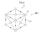
- FIG. 3 is a diagram illustrating hydrogen storage with a hydrogen storage material, specifically an example in which palladium (Pd) is used as the hydrogen storage material 19.
- the crystalline structure of palladium, the hydrogen storage material 19 is the face-centered cubic lattice, and a hydrogen molecule 101 is stored as a hydrogen atom 101a between the palladium atoms 19'. It is known that palladium stores hydrogen of 935 times as large a volume as that of palladium itself by the hydrogen storage.
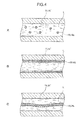
- FIGS. 4A to 4C are diagrams illustrating examples of the arrangement of the hydrogen storage material 19 in the impulse lines 11, 11'.
- the disposition state of the hydrogen storage material 19 within the impulse lines 11, 11' will be described on the basis of FIGS. 4A to 4C .
- the hydrogen storage materials 19a to 19c of FIGS. 4A to 4C described below respectively, may be used in combination.
- FIG. 4A is a diagram illustrating a configuration in which the granular hydrogen storage material 19a is mixed in the sealed liquid L filled within the impulse lines 11, 11'.
- the hydrogen storage material 19a is provided along the direction of the arrangement of the impulse lines 11, 11'.
- the granular hydrogen storage material 19a be dispersed in the sealed liquid L and thereby mixed in the sealed liquid L homogenously. This enables the hydrogen storage material 19a to influence the impulse lines 11, 11' over the nearly whole area thereof.
- the granular hydrogen storage material 19a may be powder with a small particle diameter or solids with a larger particle diameter. The smaller the diameter of the hydrogen storage material 19a becomes, the larger the surface area thereof becomes to accelerate the storage rate of hydrogen and therefore the more preferable.
- the hydrogen storage material 19a may constitute a colloidal liquid in a state of being mixed with the sealed liquid L depending on the particle size of the hydrogen storage material 19a.
- the hydrogen storage material 19a is solids with a certain size
- the shape is not limited.
- using a porous hydrogen storage material as the hydrogen storage material 19a makes the surface area thereof larger to accelerate the storage rate of hydrogen, and therefore is preferable.
- FIG. 4B is a diagram illustrating a configuration in which the hydrogen storage material 19b is provided on the wall of the impulse lines 11, 11'. In this configuration, the hydrogen storage material 19b is provided along the direction of the arrangement of the impulse lines 11, 11'.
- the hydrogen storage material 19b is provided on the inner wall of the impulse lines 11, 11', for example as a film formed with a plating method or a sputtering method.
- the wall of the impulse lines 11, 11' to be provided with the hydrogen storage material 19b includes a wall surface with which the sealed liquid L contacts in the pressure-receiving chambers 11a, 11a' and the pressure-relieving chambers 11b, 11b' described using FIG. 2 .
- the hydrogen storage material 19b be formed as a film on the inner wall of the impulse lines 11, 11' in as large an area as possible.
- the hydrogen storage material 19b is provided on the wall surface of the impulse lines 11, 11'
- a configuration in which the granular hydrogen storage material 19a described using FIG. 4A is fixed on the wall surface of the impulse lines 11, 11' may also be employed.
- This configuration can prevent the deterioration of the pressure-sensing diaphragms 13, 13' and the center diaphragm 17 due to their collision with the granular hydrogen storage material 19a with a certain size.
- the hydrogen storage material 19b may be provided on the center diaphragm 17.
- providing the hydrogen storage material 19b on both surfaces of the center diaphragm 17 contacting with the sealed liquid L enables to further increase the surface area of the hydrogen storage material 19b.
- FIG. 4C is a diagram illustrating a configuration in which the hydrogen storage material 19c is laid within the impulse lines 11, 11'.
- the hydrogen storage material 19c is, for example, rod-like and is laid along the path of the impulse lines 11, 11'. In this configuration, the hydrogen storage material 19c is provided along the direction of the arrangement of the impulse lines 11, 11'.
- the rod-like hydrogen storage material 19c may be a wire with a circular cross-section, and it is preferable to make the cross-section wide as if being pressed and extended, use a porous material as the rod-like hydrogen storage material, or lay the rod-like hydrogen storage material 19c spirally because the surface area increases to accelerate the store rate of hydrogen.
- the rod-like hydrogen storage material 19c is easy to process and can reduce the cost.
- the pressure transmitter 1 constituted as described above is provided, for example, for measurement of the water level in the drain tank 68 for the feedwater heater 65 as shown in FIG. 1 .
- the pressure transmitter 1 is provided so that a fluid flowing in the piping upstream of the drain tank 68, i.e., a fluid flowing in the feedwater piping 69 between the drain tank 68 and the condenser 61 is supplied to one pressure-sensing diaphragm 13 in the pressure transmitter 1 as the fluid to be measured Fh in the high-pressure side.
- the pressure transmitter 1 is provided so that a fluid flowing in the piping downstream of the drain tank 68, i.e., a fluid flowing in the drain piping 67 between the drain tank 68 and the feedwater heater 65 is supplied to the other pressure-sensing diaphragm 13' in the pressure transmitter 1 as the fluid to be measured Fl in the low-pressure side.
- This provides a configuration in which the differential pressure between the upstream side and the downstream side of the drain tank 68 is received by the pressure sensor 15 in the pressure transmitter 1 to be output to the output circuit 15b.
- the information from the output circuit 15b described above is transferred to the monitor 81 and the central control panel 82 (installed in the central control room, although not shown in figures) via the control unit 80. Then, the information (differential pressure) output to the output circuit 15b is monitored as the water level in the drain tank 68, and on the basis of the value the water level is controlled so as to be a given value.
- the configuration has been exemplified in which the instrumentation equipment for the nuclear power plant 10 is used for the measurement of the water level in the drain tank 68 for the feedwater heater 65.
- the position of the instrumentation equipment for the nuclear power plant 10 to be installed on is not limited to this, and in particular it is effective to employ the instrumentation equipment for the nuclear power plant 10 for various process measurement for the reactor water 52, which directly cools the reactor core 51, as a fluid to be measured.
- the instrumentation equipment for a nuclear power plant 10 is described above as one to measure the differential pressure between the upstream side and the downstream side in the system of the nuclear power plant 100, measurement is not limited to this, and for example, the instrumentation equipment for the nuclear power plant 10 may measure the gauge pressure of the fluid to be measured Fh in the high-pressure side using the atmosphere as the fluid to be measured Fl in the low-pressure side.
- the above-described feedwater system and condensation system in the nuclear power plant 100 is the primary system of the nuclear power plant and in the special environment with a high radiation dose, in which the sealed liquid L in the instrumentation equipment for the nuclear power plant 10 provided for the measurement of the water level in the drain tank 68 is subject to radiolysis.
- the reactor water 52 which directly cools the reactor core 51 in the nuclear power plant 100 is the fluid to be measured and contains a large amount of hydrogen generated due to radiolysis etc.
- This reactor water 52 is introduced as steam from the main steam piping 54 to the moisture separation heater 56, the drain tank 60, the feedwater heater 65, the condenser 61, the drain tank 68, etc.
- the reactor water 52 introduced as steam is condensed into condensed water by the moisture separation heater 56, the feedwater heater 65, etc.
- noncondensable hydrogen contained in the steam is accumulated in the upper part due to the smaller specific gravity than that of the saturated steam and the concentration gradually increases. The higher the concentration of the hydrogen accumulated in the upper part of the reactor water 52, which is the fluid to be measured, the more likely the hydrogen is to permeate the pressure-sensing diaphragms 13, 13'.
- the instrumentation equipment for the nuclear power plant 10 of the first embodiment is provided in such nuclear power plant primary system and has the configuration in which the pressure transmitter 1 having the hydrogen storage material 19 within the impulse lines 11, 11' is provided.
- the hydrogen generated due to the radiolysis of the sealed liquid L in the radiation environment or the hydrogen which permeates the pressure-sensing diaphragms 13, 13' to be incorporated in the sealed liquid L is stored in the hydrogen storage material 19.
- This enables to lower the concentration of hydrocarbons such as methane, ethane and propane in the sealed liquid L and inhibit the formation of bubbles in the impulse lines 11, 11'.
- the pressure in the impulse lines 11, 11' can be stabilized to maintain the pressure-transmission properties over a long duration, and therefore the variation of indicated values can be reduced to keep the allowable error precision of the instrumentation equipment for the nuclear power plant 10 (e.g., a precision of ⁇ 1%) for a long period of time. Due to the above results, the quantity of process can be measured within a given precision over a long duration and the cost of maintenance can be reduced. That is, reliability and maintainability can be improved. Particularly, the nearer the pressure on the upstream side and the downstream side in the piping is to the vacuum, the less the pressure of the sealed liquid L is and the solubility decreases, and therefore a remarkable effect can be achieved.
- FIG. 5 is a configuration diagram of a test apparatus for the irradiation test. As shown FIG. 5 , the irradiation test was conducted in an irradiation chamber 201. A radiation source apparatus 203 for the ⁇ -ray h ⁇ and an oil-enclosing container 207 placed on a setting table 205 were disposed in the irradiation chamber 201.
- the radiation source apparatus 203 is an apparatus which generates the ⁇ -ray h ⁇ from a cobalt radiation source, and has an irradiation port 203a for irradiating the generated ⁇ -ray h ⁇ .
- the oil-enclosing container 207 is a container made of stainless steel within which a sealed liquid being a sample for the irradiation test is filled, and disposed at the position to which the ⁇ -ray h ⁇ irradiated from the irradiation port 203a of the radiation source apparatus 203 is directed.
- the oil-enclosing container 207 is disposed away from the radiation source apparatus 203 by a given distance so that the sealed liquid filled within the container can be irradiated with a given dose of the ⁇ -ray h ⁇ .
- the irradiation test using the above-described test apparatus was conducted for two cases, i.e., the case that the methylphenyl silicone oil was filled within the oil-enclosing container 207 and the case that the dimethyl silicone oil was filled within the container.
- FIG. 6 is a graph showing the result of the analysis using a gas chromatography, i.e., the relative value of the quantity of the generated gas, which is the integration of the dose of the ⁇ -ray h ⁇ , with reference to the cumulative dose.
- the quantity of the generated hydrogen (hydrogen molecule) and methane in the methylphenyl silicone oil were less than those in the dimethyl silicone oil.
- the quantity of the generated hydrogen in the methylphenyl silicone oil at a cumulative dose of 1 kGy was less by four orders than that in the dimethyl silicone oil.
- the quantity of the generated methane in the methylphenyl silicone oil at a cumulative dose of 100 kGy was less by about an order than that in the dimethyl silicone oil.
- the quantities of hydrogen and hydrocarbons generated by irradiation in the methylphenyl silicone oil, which is used as the sealed liquid L for the pressure transmitter 1 of the first embodiment, were less than those in the dimethyl silicone oil, which is used as a sealed liquid in a common pressure transmitter.
- benzene was not detected from the methylphenyl silicone oil and the leaving of the phenyl group due to radiolysis was also suppressed.
- the quantity of the gas generated by irradiation can be significantly reduced in comparison with the case that the dimethyl silicone oil, which is used as the sealed liquid of the common pressure transmitter, is used.
- the pressure transmitter 1 of the first embodiment described using FIG. 2 has the configuration in which the hydrogen storage material 19 is provided within the impulse lines 11, 11'.
- the hydrogen is stored in the hydrogen storage material 19.
- hydrogen which permeates the pressure-sensing diaphragms 13, 13' to be incorporated in the sealed liquid L is also stored in the hydrogen storage material 19. Accordingly, the concentration of hydrocarbons such as methane, ethane and propane in the sealed liquid L can be lowered.
- the sealed liquid L in the case that the methylphenyl silicone oil is used as the sealed liquid L, the quantities of hydrogen and hydrocarbons generated by the irradiation can be still more suppressed and the concentration of hydrocarbons such as methane, ethane and propane in the sealed liquid L can be still more lowered in comparison with the case that the dimethyl silicone oil is used.
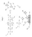
- FIG. 7 is a diagram illustrating the decomposition of methylphenyl silicone oil due to irradiation of the ⁇ -ray h ⁇ etc., and hydrogen storage with the hydrogen storage material 19.
- irradiation to the sealed liquid L consisting of the methylphenyl silicone oil L1 there exist the case that the pressure transmitter 1 is exposed to an area of radiation atmosphere and also exist the case that the sealed liquid L is irradiated by radiation contained in the fluids to be measured Fh, Fl through the pressure-sensing diaphragms 13, 13'.
- the methylphenyl silicone oil L1 used as the sealed liquid is irradiated with the ⁇ -ray h ⁇ , then a C-H bond or Si-C bond in the methylphenyl silicone oil L1 is broken. Thereby, the hydrogen atom 101a or the methyl group 102a leaves from the methylphenyl silicone oil L1.
- the generation of the hydrogen molecule 101 can be inhibited, but also the generation of the methane 102 can be inhibited because of the reduction of the quantity of the hydrogen atoms 101a to bond to the methyl group 102a.
- the case that the hydrogen storage material 19 stores hydrogen atoms in a hydrocarbon is as follows. That is, some of the hydrogen atoms 101a and the methyl groups 102a which have left from the methylphenyl silicone oil L1 due to radiolysis bond together to generate the methane 102. Thereafter, once the methane 102 contacts with the surface of the hydrogen storage material 19, the methane 102 dissociates into the methyl group 102a and the hydrogen atom 101a on the surface. The hydrogen atom 101a which has left is stored in the hydrogen storage material 19 and the methyl group 102a eventually becomes a carbon atom and is adsorbed on the surface of the hydrogen storage material 19. The same applies to ethane, propane and butane generated in the sealed liquid, and thereby can prevent the pressure from increasing within the impulse line due to the accumulation of hydrocarbons such as the methane 102 as bubbles.
- FIG. 8 is a diagram illustrating the decomposition of the silicone oil (dimethyl silicone oil) due to the irradiation of the ⁇ -ray h ⁇ etc., and hydrogen storage with the hydrogen storage material.
- the sealed liquid L consisting of the silicone oil
- the pressure transmitter 1 is exposed to an area of radiation atmosphere and also exist the case that the sealed liquid L is irradiated by radiation contained in the fluids to be measured Fh, Fl through the pressure-sensing diaphragms 13, 13'.
- the silicone oil L2 used as the sealed liquid L is irradiated with the ⁇ -ray h ⁇ , then the C-H bond or Si-C bond in the silicone oil L2 is broken. Thereby, the hydrogen atom 101a or the methyl group 102a leaves from the silicone oil L2.
- the generation of the hydrogen molecule 101 can be inhibited, but also the generation of the methane 102 can be inhibited because of the reduction of the quantity of the hydrogen atoms 101a to bond to the methyl group 102a.
- the case that the hydrogen storage material 19 stores the hydrogen atom 101a in a hydrocarbon is as follows. That is, some of the hydrogen atoms 101a and the methyl groups 102a which have left from the silicone oil L2 due to radiolysis bond together to generate the methane 102. Thereafter, once the methane 102 contacts with the surface of the hydrogen storage material 19, the methane 102 dissociates into the methyl group 102a and the hydrogen atom 101a on the surface. The hydrogen atom 101a which has left is stored in the hydrogen storage material 19 and the methyl group 102a eventually becomes a carbon atom and is adsorbed on the surface of the hydrogen storage material 19. The same applies to ethane, propane and butane generated in the sealed liquid, and thereby can prevent the pressure from increasing within the impulse line due to the accumulation of hydrocarbons such as the methane 102 as bubbles.
- the concentration of hydrocarbons such as methane, ethane and propane in the sealed liquid L can be still more lowered and the formation of bubbles in the impulse lines 11, 11' can be still more inhibited in comparison with the case that the dimethyl silicone oil is used.
- the instrumentation equipment for the nuclear power plant having such pressure transmitter has an improved reliability and maintainability in addition to the above effects.
- FIG. 9 is a diagram illustrating the configuration of a pressure transmitter, which is the principal part of the instrumentation equipment for the nuclear power plant according to the second embodiment.
- the pressure transmitter 2 illustrated in FIG. 9 is used for the pressure measurement of the reactor water 52 in the nuclear power plant primary system illustrated in FIG. 1 as a fluid to be measured, and measures the pressure difference between two points (high-pressure side and low-pressure side).
- the pressure transmitter 2 is different from the pressure transmitter 1 described using FIG. 2 in that a hydrogen-permeation-preventing layer 21 is provided on the pressure-sensing diaphragms 13, 13', and the other configurations are the same. Therefore, the same configuration as in the pressure transmitter 1 illustrated in FIG. 2 is given with the identical symbol and duplicating descriptions are omitted.
- the hydrogen-permeation-preventing layer 21 is provided on the pressure-sensing diaphragm 13, 13'.
- the hydrogen-permeation-preventing layer 21 is preferably provided on the surface layer on the side of the impulse lines 11, 11' or as an intermediate layer in the pressure-sensing diaphragms 13, 13', and disposed in a state of not contacting with the fluids to be measured Fh, Fl. This provides a configuration in which the effect of the hydrogen-permeation-preventing layer 21 on the reactor water 52 as the fluids to be measured Fh, Fl and the process system in which the fluids to be measured Fh, Fl involved can be suppressed.
- the hydrogen-permeation-preventing layer 21 includes a hydrogen storage material or a hydrogen blocking material.
- the hydrogen storage material included in the hydrogen-permeation-preventing layer 21 is the same material as the hydrogen storage material described in the first embodiment and stores hydrogen from the sides of the fluids to be measured Fh, Fl to prevent the permeation of hydrogen into the impulse lines 11, 11'. Thereby, the pressure within the impulse lines 11, 11' can be stabilized.
- the hydrogen blocking material included in the hydrogen-permeation-preventing layer 21 is a material which can block storage and permeation of hydrogen per se and thereby prevents the permeation of hydrogen from the sides of the fluids to be measured Fh, Fl into the impulse lines 11, 11'.
- a hydrogen blocking material is specifically gold, silver, copper, platinum, aluminum, chromium, titanium or an alloy thereof.
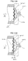
- FIGS. 10A and 10B are diagrams illustrating examples of the arrangement of the hydrogen-permeation-preventing layer 21 in the pressure-sensing diaphragm 13, 13', and enlarged views of the pressure-sensing diaphragm 13 in the high-pressure side in FIG. 9 .
- the disposition state of the hydrogen-permeation-preventing layer 21 in the pressure-sensing diaphragm 13 will be described on the basis of FIGS. 10A and 10B .
- the configuration to be described here also applies to the pressure-sensing diaphragm 13' in the low-pressure side, and therefore the configuration in the high-pressure side will be described as a representative example.
- the hydrogen-permeation-preventing layers 21a, 21b in the configurations described below in FIGS 10A and 10B respectively may be used in combination.
- FIG. 10A is a diagram illustrating the configuration in which the hydrogen-permeation-preventing layer 21a is provided on the surface layer on the side of the impulse line 11 in the pressure-sensing diaphragm 13.
- the hydrogen-permeation-preventing layer 21a is preferably provided in a state of covering as wide surface as possible in the pressure-sensing diaphragm 13 to inhibit the exposure of the pressure-sensing diaphragm 13 to the sealed liquid L.
- the hydrogen-permeation-preventing layer 21 may be provided on the whole surface of the surface layer on the side of the impulse line 11 in the pressure-sensing diaphragm 13.
- This hydrogen-permeation-preventing layer 21a is formed as a film on the surface of the pressure-sensing diaphragm 13 with a plating method, a sputtering method or the like, and it is easy to dispose on the pressure-sensing diaphragm 13.
- FIG. 10B is a diagram illustrating the configuration in which the hydrogen-permeation-preventing layer 21b is provided as an intermediate layer of the pressure-sensing diaphragm 13.
- the hydrogen-permeation-preventing layer 21b is preferably provided as a thin film held between the two pressure-sensing diaphragms 13a, 13b and has a size to close the opening of the pressure-receiving chamber 11a, which is one opening of the impulse line 11.
- this hydrogen-permeation-preventing layer 21b includes a hydrogen storage material
- the hydrogen-permeation-preventing layer 21b is not limited to a thin film and the configuration in which powder is packed tightly and held between the two pressure-sensing diaphragms 13a, 13b is also possible.
- This hydrogen-permeation-preventing layer 21b is formed as a unit as an intermediate layer of the pressure-sensing diaphragm 13 by rolling two pressure-sensing diaphragms 13a, 13b with the hydrogen-permeation-preventing layer 21b in a thin film or powder held therebetween to integrate.
- this hydrogen-permeation-preventing layer 21b never influence the sealed liquid L, not only the fluids to be measured Fh, Fl.
- the hydrogen-permeation-preventing layer 21 may be provided on only one of the pressure-sensing diaphragms 13, 13'. Moreover, in the case that the environments in which the impulse lines 11, 11' are disposed are uneven and the hydrogen storage material 19 is provided within one of the impulse lines 11, 11', a synergistic effect as described below can be obtained by providing the hydrogen-permeation-preventing layer 21 on the side on which the hydrogen storage material 19 is provided.
- the above-described instrumentation equipment for a nuclear power plant of the second embodiment is provided in a nuclear power plant primary system and has the configuration in which the pressure transmitter 2 having the pressure-sensing diaphragms 13, 13' provided with the hydrogen-permeation-preventing layers 21 is provided.
- the pressure transmitter 2 having the pressure-sensing diaphragms 13, 13' provided with the hydrogen-permeation-preventing layers 21 is provided.
- the hydrogen-permeation-preventing layer 21 is simply provided on the pressure-sensing diaphragms 13, 13', hydrogen and hydrocarbons generated due to the decomposition of the sealed liquid L are not released outside and the pressure within the impulse lines 11, 11' cannot be stabilized.
- the hydrogen storage material 19 is provided within the impulse lines 11, 11' to inhibit the formation of bubbles in the impulse lines 11, 11'.
- the methylphenyl silicone oil may be also used as the sealed liquid L for the pressure transmitter 2 illustrated in FIGS. 9 , 10 in the present embodiment.
- the concentration of hydrocarbons such as methane, ethane and propane in the sealed liquid L can be still more lowered and the formation of bubbles in the impulse lines 11, 11' can be still more inhibited in comparison with the case that the dimethyl silicone oil is used.
- the instrumentation equipment for the nuclear power plant having such pressure transmitter has an improved reliability and maintainability in addition to the above effects.
- FIG. 11 is a diagram illustrating the configuration of a pressure transmitter, which is the principal part of the instrumentation equipment for the nuclear power plant according to the third embodiment.
- the pressure transmitter 3 illustrated in FIG. 11 is used for pressure measurement of the reactor water 52 in the nuclear power plant primary system illustrated in FIG. 1 as a fluid to be measured and is for measurement of absolute pressure to measure the pressure of the fluid to be measured F.
- the pressure transmitter 3 is different from the pressure transmitter 1 described using FIG. 2 in that it has one pressure-sensing diaphragm 13 and one impulse line 11 for one pressure sensor 15 only, and the other configurations are the same.
- the other opening of the impulse line 11 is disposed only on the side of one surface of the pressure sensor 15, and the pressure of the fluid to be measured F received by the pressure-sensing diaphragm 13 provided on one opening of the impulse line 11 is detected. Further, a vacuum chamber 31 is provided on the other side of the pressure sensor 15, and a vacuum pump (not shown) is provided via the vacuum chamber 31. Thereby, the other side of the pressure sensor 15 is evacuated.
- the pressure transmitter 3 as described above may be combined with the pressure transmitter 2 described using FIGS. 9 , 10 , and for example, a hydrogen-permeation-preventing layer may be provided on the pressure-sensing diaphragm 13 in the pressure transmitter 3.
- the pressure-sensing diaphragm 13 is connected to a part of a piping in which a fluid to be measured in the nuclear power plant primary system flows.
- the methylphenyl silicone oil may be also used as the sealed liquid L for the pressure transmitter 3 illustrated in FIG. 11 in the present embodiment.
- the concentration of hydrocarbons such as methane, ethane and propane in the sealed liquid L can be still more lowered and the formation of bubbles in the impulse lines 11, 11' can be still more inhibited in comparison with the case that the dimethyl silicone oil is used.
- the instrumentation equipment for the nuclear power plant having such the pressure transmitter has an improved reliability and maintainability in addition to the above effects.
- FIG. 12 is a diagram illustrating the configuration of a pressure transmitter, which is the principal part of the instrumentation equipment for the nuclear power plant according to the fourth embodiment.
- the pressure transmitter 4 illustrated in FIG. 12 is used for pressure measurement of the reactor water 52 in the nuclear power plant primary system illustrated in FIG. 1 as a fluid to be measured and in particular suitably used under a high-temperature environment, and here will be described as the pressure transmitter for measurement of a difference of pressures between two points (high-pressure side and low-pressure side).
- the pressure transmitter 4 is different from the pressure transmitter 1 described using FIG. 2 in that the impulse lines 11, 11' are composed of a plurality of pipe parts 41, 42, ..., 41', 42', ... connected together and intermediate diaphragms 40 are provided at the connections, and the other configurations are the same. Therefore, the same configuration as in the pressure transmitter 1 illustrated in FIG. 2 is given with the identical symbol and overlapping descriptions are omitted.
- the impulse lines 11, 11' have the plurality of pipe parts 41, 42, ..., 41', 42', ..., connected in series.
- the impulse line 11 is composed of three pipe parts 41, 42, 43 and the impulse line 11' is composed of three pipe parts 41', 42', 43'.
- the pipe parts 41 to 43' constitute pressure-receiving chambers 11a, 11a' in which the opening diameter is enlarged at the opening parts of the pipe parts on the pressure-receiving side for the fluids to be measured Fh, Fl, and pressure-relieving chambers 11b, 11b' in which the opening diameter is enlarged at the other opening parts of the pipe parts.
- the pipe parts 41, 41' which are disposed on the side nearest to the fluids to be measured Fh, Fl in the respective impulse lines 11, 11' constitute replacer parts.
- the opening parts of the pressure-receiving chambers 11a, 11a' in the pipe parts 41, 41' are closed by the pressure-sensing diaphragms 13, 13', respectively.
- the impulse lines 11, 11' are installed on measurement sites in the primary system of the nuclear power plant 100.
- the impulse lines 11, 11' are connected to pipings in which the fluids to be measured flow at openings on the side closed by the pressure-sensing diaphragms 13, 13', respectively.
- the pipe parts 43, 43' which are disposed on the side nearest to the pressure sensor 15 in the respective impulse lines 11, 11' constitute a main part including the pressure sensor 15.
- the openings of the pressure-relieving chambers 11b, 11b' in the respective pipe parts 43, 43' are disposed so as to hold one center diaphragm 17 therebetween, and closed by the center diaphragm 17.
- the pipe parts 42, 42' disposed in the centers of the respective impulse lines 11, 11' constitute capillary parts, which are connection sites between the pipe parts 41, 41' constituting the replacer parts and pipe parts 43, 43' constituting the main part.
- the opening of pressure-relieving chamber 11b is disposed to be opposed to the opening of the pressure-receiving chamber 11a, and the intermediate diaphragm 40 is held at the opposing part, and the connection is closed by the intermediate diaphragms 40. That is, although the impulse lines 11, 11' have configurations in which the plurality of pipe parts 41, 42, 43, 41', 42', 43' are connected, each of the inner spaces is separated by the intermediate diaphragm 40.
- the sealed liquid L is filled within the pipe parts 41, 42, 43, 41', 42', 43' independently closed by the pressure-sensing diaphragms 13, 13', the pressure sensor 15, the center diaphragm 17 and the respective intermediate diaphragms 40.
- the sealed liquid L is the same silicone oil containing the phenyl group (e.g., methylphenyl silicone oil) as in the second embodiment.
- the pipe parts 41, 42, 43, 41', 42', 43' constituting the impulse lines 11, 11' are provided with the same hydrogen storage material in the same disposition state as in the first embodiment.
- the configuration is not limited to one in which all of the pipe parts 41, 42, 43, 41', 42', 43' contain the silicone oil containing the phenyl group as the sealed liquid L and are provided with the hydrogen storage material 19 therewithin, and this configuration may be applied to only a selected pipe part.
- the intermediate diaphragms 40 are provided in the intermediate parts of the impulse lines 11, 11' disposed between the pressure-sensing diaphragms 13, 13' and the pressure sensor 15, and are for preventing the destruction of the pressure-sensing diaphragms 13, 13' and the pressure sensor 15 due to an excess pressure.
- Such intermediate diaphragms 40 are provided so as to close the respective intermediate parts of the impulse lines 11, 11' and to separate the impulse lines 11, 11' into the plurality of pipe parts 41, 42, 43, 41', 42', 43' and expose both sides to the respective sealed liquids L.
- the intermediate diaphragm 40 serves as a buffer for the excess pressure and the destruction of the pressure-sensing diaphragms 13, 13 and the pressure sensor 15 is less likely to occur in this configuration,.
- the intermediate diaphragm 40 disposed nearest to the pressure sensor 15 constitutes the main part as a seal diaphragm.
- a hydrogen storage material may be provided on the intermediate diaphragm 40.
- the surface area of the hydrogen storage material can be further enlarged by providing the hydrogen storage material on both surfaces of the intermediate diaphragm 40 contacting with the sealed liquid L.
- the hydrogen storage material 19 may be provided within only one of the impulse lines 11, 11' or the hydrogen storage material 19 may be provided within a desired pipe part among the pipe parts 41, 42, ..., 41', 42', ... in the impulse lines 11, 11'.
- the pressure transmitter 4 as described above may be combined with the pressure transmitter 2 described using FIGS. 9 , 10 , and provided with a hydrogen-permeation-preventing layer on the pressure-sensing diaphragms 13, 13'.
- the pressure transmitter 4 for measurement of absolute pressure can be obtained by using only one of the impulse lines 11, 11' as in the case of the pressure transmitter 3 described using FIG. 11 .
- the instrumentation equipment for the nuclear power plant of the present embodiment has been described as one to measure the differential pressure between two points, however is not limited to this and for example, may measure the gauge pressure of the fluid to be measured Fh in the high-pressure side using the atmosphere as the fluid to be measured Fl in the low-pressure side.
- the above-described instrumentation equipment for the nuclear power plant of the fourth embodiment is used in a high-temperature environment, and therefore is instantaneously exposed to a high-temperature atmosphere (e.g., higher than 300°C) in some cases. Even in such a case, the same effect as in the first embodiment can be obtained because the instrumentation equipment for the nuclear power plant has the configuration in which the pressure transmitter 4 having the hydrogen storage material within the pipe parts 41, 42, 43, 41', 42', 43' constituting the impulse lines 11, 11' is provided. Moreover, the same effect as in the second embodiment can be obtained by combining with the second embodiment, i.e., employing the configuration in which the hydrogen-permeation-preventing layers are provided on the pressure-sensing diaphragms 13, 13'.
- the methylphenyl silicone oil may be also used as the sealed liquid L for the pressure transmitter 4 illustrated in FIG. 12 in the present embodiment.
- the concentration of hydrocarbons such as methane, ethane and propane in the sealed liquid L can be still more lowered and formation of bubbles in the impulse lines 11, 11' can be still more inhibited in comparison with the case that the dimethyl silicone oil is used.
- instrumentation equipment for the nuclear power plant having such pressure transmitter has an improved reliability and maintainability in addition to the above effects.
- instrumentation equipment for the nuclear power plant of the first to fourth embodiments can be used for process measurement in the nuclear power plant primary system.
- instrumentation equipment for the nuclear power plant having a configuration in combination of these configurations may also be used.
- the instrumentation equipment for the nuclear power plant of the third embodiment or one having a configuration combined with this is used.
- the nuclear power plant with which the instrumentation equipment for the nuclear power plant of the present invention is provided is not limited to the above-described boiling water reactor type, and for example, may be a nuclear power plant of pressurized water reactor (PWR) type. Also in this case, the same effect can be obtained by using the instrumentation equipment for the nuclear power plant of the present invention for various process measurement for reactor water (primary cooling water) which directly cools the reactor core as a fluid to be measured.
- reactor water primary cooling water
- control lines and information lines shown are those considered to be necessary for the description, and not all of the control lines and information lines are shown in the product. It may be considered that in fact almost all of the configurations are connected to each other.
Landscapes
- Physics & Mathematics (AREA)
- Engineering & Computer Science (AREA)
- Plasma & Fusion (AREA)
- General Engineering & Computer Science (AREA)
- High Energy & Nuclear Physics (AREA)
- General Physics & Mathematics (AREA)
- Measuring Fluid Pressure (AREA)
Applications Claiming Priority (1)
| Application Number | Priority Date | Filing Date | Title |
|---|---|---|---|
| JP2014025041A JP6199765B2 (ja) | 2014-02-13 | 2014-02-13 | 原子力プラント計装装置 |
Publications (1)
| Publication Number | Publication Date |
|---|---|
| EP2908111A1 true EP2908111A1 (en) | 2015-08-19 |
Family
ID=52462255
Family Applications (1)
| Application Number | Title | Priority Date | Filing Date |
|---|---|---|---|
| EP15154576.1A Withdrawn EP2908111A1 (en) | 2014-02-13 | 2015-02-10 | Instrumentation equipment for nuclear power plant |
Country Status (4)
| Country | Link |
|---|---|
| US (1) | US20150228365A1 (enExample) |
| EP (1) | EP2908111A1 (enExample) |
| JP (1) | JP6199765B2 (enExample) |
| CN (1) | CN104848981A (enExample) |
Families Citing this family (7)
| Publication number | Priority date | Publication date | Assignee | Title |
|---|---|---|---|---|
| JP2015078944A (ja) * | 2013-10-18 | 2015-04-23 | 株式会社日立製作所 | 圧力伝送装置 |
| JP2015078945A (ja) * | 2013-10-18 | 2015-04-23 | 株式会社日立製作所 | 圧力伝送器 |
| JP6283266B2 (ja) * | 2014-06-05 | 2018-02-21 | 株式会社日立ハイテクソリューションズ | 圧力計測装置 |
| CN106653118B (zh) * | 2016-12-07 | 2018-03-06 | 中国核工业第五建设有限公司 | 充压测试系统及方法 |
| CN110501033B (zh) * | 2018-05-17 | 2025-12-02 | 艾默生(北京)仪表有限公司 | 测量元件及包括此种测量元件的测量装置 |
| EP3769063B1 (en) | 2018-05-17 | 2023-01-04 | Rosemount Inc. | Measuring element and measuring device comprising the same |
| CN111519051A (zh) * | 2020-04-21 | 2020-08-11 | 上海申核能源工程技术有限公司 | 一种核设施事故后用吸氢材料配置工艺 |
Citations (7)
| Publication number | Priority date | Publication date | Assignee | Title |
|---|---|---|---|---|
| US5566571A (en) * | 1994-03-29 | 1996-10-22 | Kabushiki Kaisha Toshiba | Differential pressure detecting equipment capable of preventing accumulation of non-condensible gases |
| JP2004361159A (ja) * | 2003-06-03 | 2004-12-24 | Fuji Electric Systems Co Ltd | リモートシール形圧力・差圧発信器 |
| JP2005114453A (ja) | 2003-10-06 | 2005-04-28 | Yokogawa Electric Corp | 差圧測定装置 |
| US20050126296A1 (en) * | 2003-12-16 | 2005-06-16 | Rosemount Inc. | Remote process seal with improved stability in demanding applications |
| US20080168777A1 (en) * | 2007-01-11 | 2008-07-17 | Siemens Magnet Technology Ltd. | Cryostat for Transporting Cooled Equipment at a Cryogenic Temperature |
| JP2011185758A (ja) * | 2010-03-09 | 2011-09-22 | Yokogawa Electric Corp | 圧力測定器 |
| US20130312531A1 (en) * | 2012-05-22 | 2013-11-28 | Robert C. Hedtke | Pressure transmitter with hydrogen getter |
Family Cites Families (8)
| Publication number | Priority date | Publication date | Assignee | Title |
|---|---|---|---|---|
| JPS5943725B2 (ja) * | 1975-05-05 | 1984-10-24 | ポラロイド、コ−ポレ−シヨン | カメラの露出制御装置 |
| JPS5874144U (ja) * | 1981-11-14 | 1983-05-19 | 横河電機株式会社 | 差圧・圧力計 |
| JP3182807B2 (ja) * | 1991-09-20 | 2001-07-03 | 株式会社日立製作所 | 多機能流体計測伝送装置及びそれを用いた流体量計測制御システム |
| JP3314349B2 (ja) * | 1995-10-16 | 2002-08-12 | 株式会社日立製作所 | 圧力伝送器 |
| US5837158A (en) * | 1996-09-23 | 1998-11-17 | Sandia Corporation | Polymer formulations for gettering hydrogen |
| JP2003156399A (ja) * | 2001-11-22 | 2003-05-30 | Toyoda Mach Works Ltd | 半導体圧力検出装置 |
| JP2014020953A (ja) * | 2012-07-19 | 2014-02-03 | Azbil Corp | 差圧・圧力発信器 |
| JP2015078945A (ja) * | 2013-10-18 | 2015-04-23 | 株式会社日立製作所 | 圧力伝送器 |
-
2014
- 2014-02-13 JP JP2014025041A patent/JP6199765B2/ja active Active
-
2015
- 2015-01-08 CN CN201510009345.8A patent/CN104848981A/zh active Pending
- 2015-02-10 EP EP15154576.1A patent/EP2908111A1/en not_active Withdrawn
- 2015-02-11 US US14/619,261 patent/US20150228365A1/en not_active Abandoned
Patent Citations (7)
| Publication number | Priority date | Publication date | Assignee | Title |
|---|---|---|---|---|
| US5566571A (en) * | 1994-03-29 | 1996-10-22 | Kabushiki Kaisha Toshiba | Differential pressure detecting equipment capable of preventing accumulation of non-condensible gases |
| JP2004361159A (ja) * | 2003-06-03 | 2004-12-24 | Fuji Electric Systems Co Ltd | リモートシール形圧力・差圧発信器 |
| JP2005114453A (ja) | 2003-10-06 | 2005-04-28 | Yokogawa Electric Corp | 差圧測定装置 |
| US20050126296A1 (en) * | 2003-12-16 | 2005-06-16 | Rosemount Inc. | Remote process seal with improved stability in demanding applications |
| US20080168777A1 (en) * | 2007-01-11 | 2008-07-17 | Siemens Magnet Technology Ltd. | Cryostat for Transporting Cooled Equipment at a Cryogenic Temperature |
| JP2011185758A (ja) * | 2010-03-09 | 2011-09-22 | Yokogawa Electric Corp | 圧力測定器 |
| US20130312531A1 (en) * | 2012-05-22 | 2013-11-28 | Robert C. Hedtke | Pressure transmitter with hydrogen getter |
Also Published As
| Publication number | Publication date |
|---|---|
| CN104848981A (zh) | 2015-08-19 |
| US20150228365A1 (en) | 2015-08-13 |
| JP2015152373A (ja) | 2015-08-24 |
| JP6199765B2 (ja) | 2017-09-20 |
Similar Documents
| Publication | Publication Date | Title |
|---|---|---|
| EP2908111A1 (en) | Instrumentation equipment for nuclear power plant | |
| CN104568294B (zh) | 压力传送装置 | |
| JP2015078945A (ja) | 圧力伝送器 | |
| Sun et al. | The effect of Cl-and acetic acid on localized CO2 corrosion in wet gas flow | |
| TW591221B (en) | Improved hydrogen permeation probe | |
| CN110068428B (zh) | 一种碘吸附器泄漏率在线测量系统及其测量方法 | |
| Mohammed Nor et al. | Corrosion of carbon steel in high CO2 containing environments-The effect of high flow rate | |
| CN202471554U (zh) | 氢扩散渗透特性测量装置 | |
| Jurns et al. | Bubble point measurements with liquid methane of a screen capillary liquid acquisition device | |
| Glatzmaier | Hydrogen sensor for parabolic trough expansion tanks | |
| US20180073956A1 (en) | System and method for monitoring hydrogen flux | |
| Glatzmaier | Development of Hydrogen Mitigation for the Nevada Solar One Power Plant | |
| US9939339B2 (en) | Pressure transmitter device | |
| Hay et al. | Electrochemical monitoring of carbon steel corrosion in heavy water production | |
| JP2013015504A (ja) | 水蒸気透過測定システム | |
| Glatzmaier | Acciona power plant hydrogen mitigation project | |
| Glatzmaier | Abengoa/Acciona Power Plant Hydrogen Mitigation Project (Cooperative Research and Development Final Report, CRADA Number CRD-15-583) | |
| Kuwana et al. | ICONE23-1424 DEVELOPMENT OF METHOD OF DRIFT SUPPRESSION FOR PRESSURE TRANSMITTERS CONTAINING PALLADIUM | |
| Kitanin et al. | Method of measuring the quantity of air liberated in aviation fuel flow at low pipeline pressure | |
| Alvis | Comparison of waterflood corrosion detection and monitoring devices | |
| RU2561016C1 (ru) | Установка измерения и учета сжиженного углеводородного газа | |
| Corneli et al. | Memory effects in measurements of low tritium concentrations as required for the outlet of the TEP system of the ITER fuel cycle | |
| US10712242B2 (en) | Mercury-in-gas sampling system | |
| Li et al. | WGS-mixture separation and WGS reaction test in a bench-scale multi-tubular membrane reactor | |
| Schmitt et al. | Measuring Corrosivity as Simple as Temperature? |
Legal Events
| Date | Code | Title | Description |
|---|---|---|---|
| PUAI | Public reference made under article 153(3) epc to a published international application that has entered the european phase |
Free format text: ORIGINAL CODE: 0009012 |
|
| 17P | Request for examination filed |
Effective date: 20150610 |
|
| AK | Designated contracting states |
Kind code of ref document: A1 Designated state(s): AL AT BE BG CH CY CZ DE DK EE ES FI FR GB GR HR HU IE IS IT LI LT LU LV MC MK MT NL NO PL PT RO RS SE SI SK SM TR |
|
| AX | Request for extension of the european patent |
Extension state: BA ME |
|
| STAA | Information on the status of an ep patent application or granted ep patent |
Free format text: STATUS: EXAMINATION IS IN PROGRESS |
|
| 17Q | First examination report despatched |
Effective date: 20181213 |
|
| STAA | Information on the status of an ep patent application or granted ep patent |
Free format text: STATUS: THE APPLICATION IS DEEMED TO BE WITHDRAWN |
|
| 18D | Application deemed to be withdrawn |
Effective date: 20191120 |