EP2907437A2 - Robot cleaner - Google Patents
Robot cleaner Download PDFInfo
- Publication number
- EP2907437A2 EP2907437A2 EP15154740.3A EP15154740A EP2907437A2 EP 2907437 A2 EP2907437 A2 EP 2907437A2 EP 15154740 A EP15154740 A EP 15154740A EP 2907437 A2 EP2907437 A2 EP 2907437A2
- Authority
- EP
- European Patent Office
- Prior art keywords
- brush
- auxiliary
- main
- robot cleaner
- connection member
- Prior art date
- Legal status (The legal status is an assumption and is not a legal conclusion. Google has not performed a legal analysis and makes no representation as to the accuracy of the status listed.)
- Granted
Links
- 239000000428 dust Substances 0.000 claims abstract description 37
- 238000009434 installation Methods 0.000 claims description 42
- 239000002245 particle Substances 0.000 description 6
- 230000008878 coupling Effects 0.000 description 5
- 238000010168 coupling process Methods 0.000 description 5
- 238000005859 coupling reaction Methods 0.000 description 5
- 238000004140 cleaning Methods 0.000 description 4
- 239000000463 material Substances 0.000 description 2
- 230000003247 decreasing effect Effects 0.000 description 1
- 230000001747 exhibiting effect Effects 0.000 description 1
- 238000000034 method Methods 0.000 description 1
- 239000000843 powder Substances 0.000 description 1
Images


Classifications
-
- A—HUMAN NECESSITIES
- A47—FURNITURE; DOMESTIC ARTICLES OR APPLIANCES; COFFEE MILLS; SPICE MILLS; SUCTION CLEANERS IN GENERAL
- A47L—DOMESTIC WASHING OR CLEANING; SUCTION CLEANERS IN GENERAL
- A47L9/00—Details or accessories of suction cleaners, e.g. mechanical means for controlling the suction or for effecting pulsating action; Storing devices specially adapted to suction cleaners or parts thereof; Carrying-vehicles specially adapted for suction cleaners
- A47L9/02—Nozzles
- A47L9/04—Nozzles with driven brushes or agitators
- A47L9/0405—Driving means for the brushes or agitators
- A47L9/0411—Driving means for the brushes or agitators driven by electric motor
-
- A—HUMAN NECESSITIES
- A47—FURNITURE; DOMESTIC ARTICLES OR APPLIANCES; COFFEE MILLS; SPICE MILLS; SUCTION CLEANERS IN GENERAL
- A47L—DOMESTIC WASHING OR CLEANING; SUCTION CLEANERS IN GENERAL
- A47L11/00—Machines for cleaning floors, carpets, furniture, walls, or wall coverings
- A47L11/24—Floor-sweeping machines, motor-driven
-
- A—HUMAN NECESSITIES
- A47—FURNITURE; DOMESTIC ARTICLES OR APPLIANCES; COFFEE MILLS; SPICE MILLS; SUCTION CLEANERS IN GENERAL
- A47L—DOMESTIC WASHING OR CLEANING; SUCTION CLEANERS IN GENERAL
- A47L11/00—Machines for cleaning floors, carpets, furniture, walls, or wall coverings
- A47L11/40—Parts or details of machines not provided for in groups A47L11/02 - A47L11/38, or not restricted to one of these groups, e.g. handles, arrangements of switches, skirts, buffers, levers
- A47L11/4036—Parts or details of the surface treating tools
- A47L11/4041—Roll shaped surface treating tools
-
- A—HUMAN NECESSITIES
- A47—FURNITURE; DOMESTIC ARTICLES OR APPLIANCES; COFFEE MILLS; SPICE MILLS; SUCTION CLEANERS IN GENERAL
- A47L—DOMESTIC WASHING OR CLEANING; SUCTION CLEANERS IN GENERAL
- A47L11/00—Machines for cleaning floors, carpets, furniture, walls, or wall coverings
- A47L11/40—Parts or details of machines not provided for in groups A47L11/02 - A47L11/38, or not restricted to one of these groups, e.g. handles, arrangements of switches, skirts, buffers, levers
- A47L11/4036—Parts or details of the surface treating tools
- A47L11/4044—Vacuuming or pick-up tools; Squeegees
-
- A—HUMAN NECESSITIES
- A47—FURNITURE; DOMESTIC ARTICLES OR APPLIANCES; COFFEE MILLS; SPICE MILLS; SUCTION CLEANERS IN GENERAL
- A47L—DOMESTIC WASHING OR CLEANING; SUCTION CLEANERS IN GENERAL
- A47L11/00—Machines for cleaning floors, carpets, furniture, walls, or wall coverings
- A47L11/40—Parts or details of machines not provided for in groups A47L11/02 - A47L11/38, or not restricted to one of these groups, e.g. handles, arrangements of switches, skirts, buffers, levers
- A47L11/4063—Driving means; Transmission means therefor
- A47L11/4069—Driving or transmission means for the cleaning tools
-
- A—HUMAN NECESSITIES
- A47—FURNITURE; DOMESTIC ARTICLES OR APPLIANCES; COFFEE MILLS; SPICE MILLS; SUCTION CLEANERS IN GENERAL
- A47L—DOMESTIC WASHING OR CLEANING; SUCTION CLEANERS IN GENERAL
- A47L9/00—Details or accessories of suction cleaners, e.g. mechanical means for controlling the suction or for effecting pulsating action; Storing devices specially adapted to suction cleaners or parts thereof; Carrying-vehicles specially adapted for suction cleaners
- A47L9/02—Nozzles
- A47L9/04—Nozzles with driven brushes or agitators
- A47L9/0427—Gearing or transmission means therefor
- A47L9/0433—Toothed gearings
- A47L9/0438—Toothed gearings with gears having orbital motion, e.g. planetary gearing
-
- A—HUMAN NECESSITIES
- A47—FURNITURE; DOMESTIC ARTICLES OR APPLIANCES; COFFEE MILLS; SPICE MILLS; SUCTION CLEANERS IN GENERAL
- A47L—DOMESTIC WASHING OR CLEANING; SUCTION CLEANERS IN GENERAL
- A47L9/00—Details or accessories of suction cleaners, e.g. mechanical means for controlling the suction or for effecting pulsating action; Storing devices specially adapted to suction cleaners or parts thereof; Carrying-vehicles specially adapted for suction cleaners
- A47L9/02—Nozzles
- A47L9/04—Nozzles with driven brushes or agitators
- A47L9/0461—Dust-loosening tools, e.g. agitators, brushes
- A47L9/0466—Rotating tools
- A47L9/0477—Rolls
-
- A—HUMAN NECESSITIES
- A47—FURNITURE; DOMESTIC ARTICLES OR APPLIANCES; COFFEE MILLS; SPICE MILLS; SUCTION CLEANERS IN GENERAL
- A47L—DOMESTIC WASHING OR CLEANING; SUCTION CLEANERS IN GENERAL
- A47L2201/00—Robotic cleaning machines, i.e. with automatic control of the travelling movement or the cleaning operation
Definitions
- the main brush may be connected to the auxiliary brush via a second connection member.
- the motor may include a rotary shaft provided in a first direction
- the main brush and the auxiliary brush may each include a rotary shaft provided in the first direction
- the at least one side brush may include a rotary shaft provided in a second direction perpendicular to the first direction.
- the robot cleaner may further include an installation unit defining the suction port, wherein the installation unit may include a first installation unit, in which the main brush may be installed, and a second installation unit, in which the auxiliary brush may be installed.
- the first installation unit and the second installation unit may be provided to receive at least a portion of the main brush and at least a portion of the auxiliary brush, respectively.
- the main body 10 may include a suction port 15 to suction dust from the surface to be cleaned during travel of the main body 10.
- the suction port 15 may be provided at the bottom of the main body 10.
- the brush assembly 100 may be disposed in the suction port 15.
- the brush assembly 100 may include a main brush 20, an auxiliary brush 30, and a side brush 40.
- Coupling for a third connection member 45a may be applied in addition to coupling for the first connection member 72 and the second connection member 35 as previously described.
- the auxiliary gear 36 provided at one side of the auxiliary brush 30 may be coupled to a horizontal gear of the third connection member 45a and the horizontal gear may be connected to the second connection member 35 and a worm gear 46a. That is, the worm gear 46a extends in an axial direction of the horizontal gear and the horizontal gear is engaged with the gear of the second connection member 35.
Abstract
Description
- The present invention relates to a robot cleaner that drives various brushes using a single motor.
- A robot cleaner is an appliance that suctions foreign matter, such as dust, from an area to be cleaned so as to automatically clean the area while autonomously traveling in the area without user manipulation.
- The robot cleaner detects the distance to an obstacle, such as furniture, office supplies, or walls, located in the area through various sensors and cleans the area while avoiding collision with the obstacle using detected information.
- A fan is rotated by a motor to generate suction force and dust is scattered by a brush unit. Consequently, the robot cleaner suctions the dust together with external air. The motor is disposed under the fan along the same rotary shaft. When the rotary shaft is rotated by the motor, the fan connected to the rotary shaft is rotated to generate suction force.
- The robot cleaner may include various brushes to more effectively suction dust. For example, the robot cleaner may include a main brush disposed in a suction port and a side brush disposed at a side of the suction port.
- The main brush and the side brush are rotated by different motors. As a result, material cost is increased and the size of the robot cleaner is also increased.
- In a case in which the height of the suction port is large, large-sized dust particles may be suctioned through the suction port but suction force is decreased. On the other hand, in a case in which the height of the suction port is small, suction force is increased but large-sized dust particles may not be suctioned through the suction port.
- The foregoing described problems may be overcome and/or other aspects may be achieved by one or more embodiments of a robot cleaner that drives various brushes using a single motor.
- The foregoing described problems may be overcome and/or other aspects may be achieved by one or more embodiments of a robot cleaner including an auxiliary brush rotatable to move dust to a suction port, thereby assisting operation of a main brush.
- Additional aspects of one or more embodiments will be set forth in part in the description which follows and, in part, will be obvious from the description, or may be learned by practice of one or more embodiments.
- In accordance with one or more embodiments, a robot cleaner to remove dust from a surface to be cleaned may include a main body having a suction port, a main brush rotatably disposed in the suction port, an auxiliary brush rotatably disposed adjacent to the main brush, and at least one side brush rotatably installed to move the dust to the suction port, wherein the main brush, the auxiliary brush, and the at least one side brush may be driven by a single motor in an interlocking fashion.
- The main brush and the auxiliary brush may be arranged in parallel to each other. The main brush and the auxiliary brush may each include a rotary shaft parallel to the surface and the at least one side brush may include a rotary shaft perpendicular to the surface.
- The motor may be connected to the main brush via a first connection member and the first connection member may interconnect a rotary shaft of the motor and one side of the main brush.
- The main brush may be connected to the auxiliary brush via a second connection member.
- The second connection member may interconnect one side of the main brush and one side of the auxiliary brush.
- The second connection member may include at least one gear to interconnect the main brush and the auxiliary brush such that the main brush and the auxiliary brush may be rotatable in the same direction.
- The second connection member may interconnect the one side of the main brush, one side of the auxiliary brush, and the at least one side brush.
- The second connection member may include a plurality of gears having different speed reduction ratios such that the main brush, the auxiliary brush, and the at least one side brush may be rotatable at different speeds.
- The auxiliary brush may be connected to the at least one side brush via a third connection member.
- The third connection member may include a plurality of gears to interconnect the auxiliary brush rotating about a horizontal shaft and the at least one side brush rotating about a vertical shaft.
- The main body may include an installation unit defining the suction port and the installation unit may include a first installation unit, in which the main brush may be installed, and a second installation unit, in which the auxiliary brush may be installed.
- The auxiliary brush may include at least one blade to move the dust on the surface to the suction port.
- The at least one blade may protrude perpendicular to an axial direction of the auxiliary brush to move the dust according to rotation of the auxiliary brush.
- The auxiliary brush may be disposed in front of the main brush to move the dust on the surface to the suction port.
- In accordance with one or more embodiments, a robot cleaner may include a motor, a main brush connected to the motor via a first connection member such that the main brush is rotatable, an auxiliary brush connected to the main brush via a second connection member such that the auxiliary brush may be rotatable while being interlocked with the main brush, and at least one side brush connected to the auxiliary brush via a third connection member such that the at least one side brush may be rotatable while being interlocked with the auxiliary brush.
- The second connection member and the third connection member may each include at least one gear.
- The at least one gear may be coupled at different speed reduction ratios such that the main brush, the auxiliary brush, and the at least one side brush may be rotatable at different speeds.
- The motor may include a rotary shaft provided in a first direction, the main brush and the auxiliary brush may each include a rotary shaft provided in the first direction, and the at least one side brush may include a rotary shaft provided in a second direction perpendicular to the first direction.
- The second connection member may be installed such that the second connection member may be rotatable about a rotary shaft provided in the first direction to interconnect the main brush and the auxiliary brush disposed in the first direction. The third connection member may include at least one gear to interconnect the auxiliary brush disposed in the first direction and the at least one side brush provided in the second direction.
- In accordance with one or more embodiments, a robot cleaner may include a main brush rotatably installed in a suction port and an auxiliary unit installed adjacent to the main brush, wherein the auxiliary unit may include an auxiliary brush installed to rotate about a rotary shaft provided in parallel to a rotary shaft of the main brush and at least one blade attached to the auxiliary brush to move dust to the suction port.
- The robot cleaner may further include an installation unit defining the suction port, wherein the installation unit may include a first installation unit, in which the main brush may be installed, and a second installation unit, in which the auxiliary brush may be installed.
- The first installation unit and the second installation unit may be provided to receive at least a portion of the main brush and at least a portion of the auxiliary brush, respectively.
- The auxiliary unit may further include a connection member installed to interconnect one side of the main brush and one side of the auxiliary brush such that the auxiliary brush may be rotatable while being interlocked with the main brush.
- The connection member may be installed such that the main brush and the auxiliary brush may be rotatable in the same direction.
- The connection member may include a plurality of gears having different speed reduction ratios such that the main brush and the auxiliary brush may be rotatable at different speeds.
- The at least one blade may protrude from the auxiliary brush to scatter dust on a surface to be cleaned while rotating according to rotation of the auxiliary brush.
- These and/or other aspects will become apparent and more readily appreciated from the following description of embodiments, taken in conjunction with the accompanying drawings of which:
-
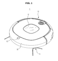
FIG. 1 is a view showing a robot cleaner according to one or more embodiments; -
FIG. 2 is a view showing the bottom of a robot cleaner according to one or more embodiments; -
FIG. 3 is a view showing an installation unit of a robot cleaner according to one or more embodiments; -
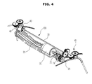
FIG. 4 is a view showing a brush assembly of a robot cleaner according to one or more embodiments; -
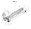
FIG. 5 is a view showing a main brush and an auxiliary brush of a robot cleaner according to one or more embodiments; -
FIGS. 6A and6B are views showing operation of an auxiliary brush of a robot cleaner according to one or more embodiments; -
FIG. 7 is a view showing a first side brush of a robot cleaner according to one or more embodiments; and -
FIG. 8 is a view showing a second side brush of a robot cleaner according to one or more embodiments. - Reference will now be made in detail to one or more embodiments, examples of which are illustrated in the accompanying drawings, wherein like reference numerals refer to like elements throughout.
-
FIG. 1 is a view showing arobot cleaner 1 according to one or more embodiments andFIG. 2 is a view showing the bottom of arobot cleaner 1 according to one or more embodiments. - The
robot cleaner 1 may include amain body 10 forming the external appearance thereof and a brush assembly 100 (seeFIG. 4 ) to sweep or scatter dust on a surface to be cleaned. The dust may mean dirt, motes, powder, scraps, and other dust particles which may be collected by an automatic or semi-automatic cleaning device including the robot cleaner. - The
main body 10 may have various shapes. For example, themain body 10 may be formed in a circular shape. The circularmain body 10 may have a uniform turning radius. During turning of themain body 10, therefore, themain body 10 may avoid contact with adjacent obstacles and may easily perform a change of direction. In addition, during travel of themain body 10, themain body 10 may be prevented from being caught by an obstacle and thus being jammed. In another example, themain body 10 may be formed in a quadrangular shape. In this case, cleaning may be satisfactorily performed even at a corner where walls are connected to each other. - The
main body 10 may be provided at the top thereof with adisplay unit 12 to display various kinds of information, such as an operation state of therobot cleaner 1, quantity of dust, a battery charge level, and time. In addition, themain body 10 may be provided at the front thereof with asensor window 50, upon which light reflected by an obstacle or a wall is incident, and avision window 60 to acquire an image of a view above themain body 10 perpendicular to a travel direction. Therobot cleaner 1 may determine a zone to be cleaned and move on a surface to be cleaned through thesensor window 50 and thevision window 60. - The
main body 10 may include drivingwheels 90, by which the main body moves about the surface to be cleaned. Two drivingwheels 90 may be symmetrically disposed at left and right edges of the middle area of the bottom of themain body 10. In addition, themain body 10 may further include a plurality ofauxiliary wheels 80 to smooth motion of therobot cleaner 1 moving through the drivingwheels 90. - During cleaning, the
robot cleaner 1 may move forward, move backward, or turn around due to the drivingwheels 90 and theauxiliary wheels 80. For example, the two drivingwheels 90 may be uniformly controlled such that therobot cleaner 1 moves forward or backward. In another example, the drivingwheels 90 may be separately controlled such that therobot cleaner 1 turns around. - In addition, the
main body 10 may include asuction port 15 to suction dust from the surface to be cleaned during travel of themain body 10. Thesuction port 15 may be provided at the bottom of themain body 10. Thebrush assembly 100 may be disposed in thesuction port 15. Thebrush assembly 100 may include amain brush 20, anauxiliary brush 30, and aside brush 40. - The
main brush 20 may be rotatably disposed in thesuction port 15. Themain brush 20 may sweep dust on a floor adjacent to thesuction port 15 to guide the dust to thesuction port 15. In thesuction portion 15 may be provided a blower (not shown) to move the dust introduced into the suction port 14 to a dust collector (not shown) provided in themain body 10. - The
auxiliary brush 30 may be rotatably disposed adjacent to themain brush 20. Themain brush 20 and theauxiliary brush 30 may be arranged in parallel to each other. Theauxiliary brush 30 will hereinafter be described in detail. - The
side brush 40 may be provided to clean a side part or a corner part of themain body 10. Theside brush 40 may be rotatably mounted at one side of the edge of the bottom of themain body 10. Theside brush 40 may be mounted at a front diagonal position deviating from a middle area of themain body 10. - The
side brush 40 may move dust around themain body 10 to thesuction port 15. Theside brush 40 may extend a cleaning range of therobot cleaner 1 to the circumference of themain body 10 including the bottom of themain body 10. As shown inFIGS. 1 and2 , a pair of side brushes 40 may be provided at the front of themain body 10. Only one side brush may be provided as needed. That is, therobot cleaner 1 may include at least oneside brush 40. -
FIG. 3 is a view showing aninstallation unit 17 of arobot cleaner 1 according to one or more embodiments andFIG. 4 is a view showing abrush assembly 100 of a robot cleaner according to one or more embodiments. - The
main body 10 may include aninstallation unit 17, in which thebrush assembly 100 may be installed. Thebrush assembly 100 may be rotatably mounted in theinstallation unit 17. Theinstallation unit 17 may define a space in which themain brush 20, theauxiliary brush 30, and theside brush 40 may be installed. In addition, theinstallation unit 17 may include auxiliarywheel receiving parts 82 to receive theauxiliary wheels 80. - The
installation unit 17 may include afirst installation unit 22 defining thesuction port 15. Themain brush 20 may be disposed in thefirst installation unit 22. Asecond installation unit 32 may be provided adjacent to thefirst installation unit 22. Theauxiliary brush 30 may be disposed in thesecond installation unit 32. Athird installation unit 42, in which theside brush 40 may be received, may be provided at each side of thefirst installation unit 22 and thesecond installation unit 32. - A
motor 70 to provide power to thebrush assembly 100 may be disposed at the upper part of theinstallation unit 17. As shown inFIG. 4 , themain brush 20, theauxiliary brush 30, and theside brush 40 may be connected to one another such that themain brush 20, theauxiliary brush 30, and theside brush 40 may be driven by themotor 70 in an interlocking fashion. Themain brush 20, theauxiliary brush 30, and theside brush 40 may be provided in various forms to receive power from themotor 70. - For example, the
main brush 20 may be connected to themotor 70 to receive power from themotor 70 and the power may be transmitted from themain brush 20 to theauxiliary brush 30 and theside brush 40. As shown inFIG. 4 , themain brush 20 and themotor 70 may be connected to each other via afirst connection member 74. In addition, themain brush 20 and theauxiliary brush 30 may be connected to each other via asecond connection member 35 and theauxiliary brush 30 and theside brush 40 may be connected to each other via athird connection member 45. - The
installation unit 17 may include a second connectionmember installation unit 34 disposed between thesecond installation unit 32 and thethird installation unit 42. Thethird connection member 45 may be disposed in thethird installation unit 42. Thefirst connection member 74 may be disposed at one side of thefirst installation unit 22. - As shown in
FIG. 4 , themotor 70, themain brush 20, and theauxiliary brush 30 may include rotary shafts parallel to the surface to be cleaned and theside brush 40 may include a rotary shaft perpendicular to the surface to be cleaned. That is, when arotary shaft 72 of themotor 70 is provided in a first direction, themain brush 20 and theauxiliary brush 30 may include rotary shafts provided in the first direction and theside brush 40 may include a rotary shaft provided in a second direction perpendicular to the first direction. - Consequently, the
second connection member 35 may be rotatably installed along a rotary shaft provided in the first direction to interconnect themain brush 20 and theauxiliary brush 30 disposed in parallel to each other in the first direction. In addition, thethird connection member 45 may include aworm gear 46 to interlock theauxiliary brush 30 and theside brush 40 perpendicularly coupled to each other. - Hereinafter, a coupling relationship between the
motor 70 and thebrush assembly 100 and the shape of thebrush assembly 100 will be described in detail. -
FIG. 5 is a view showing themain brush 20 and theauxiliary brush 30 of a robot cleaner according to one or more embodiments. For the convenience of description, theside brush 40 is omitted fromFIG. 5 . - As previously described, the
motor 70, themain brush 20, and theauxiliary brush 30 may rotate about the rotary shafts extending in the same direction. As shown inFIG. 5 , themotor 70, themain brush 20, and theauxiliary brush 30 may be arranged in parallel to one another. - The
motor 70 may include arotary shaft 72 protruding from one side thereof. Thefirst connection member 74 may connect therotary shaft 72 of themotor 70 to themain brush 20. Themain brush 20 may be formed in the shape of a rotatable drum. Themain brush 20 may include a plurality ofbrushes 23 disposed at the outer circumference thereof. Thebrushes 23 may be made of various materials exhibiting elasticity. - A
main gear 26 may be coupled to one side of themain brush 20. Themain gear 26 may be connected to therotary shaft 72 of themotor 70 via thefirst connection member 74 such that themain brush 20 receives power from themotor 70. As shown inFIG. 5 , thefirst connection member 74 may be provided, for example, in the form of a belt to connect themain gear 26 to therotary shaft 72 of themotor 70.
Theauxiliary brush 30 may be provided as a rotary shaft arranged in parallel to themain brush 20 and extending in the same direction. Theauxiliary brush 30 may be disposed in front of themain brush 20 to move dust on the surface to be cleaned to thesuction port 15. - The
auxiliary brush 30 may be connected to themain brush 20 via thesecond connection member 35 to receive power from themotor 70. Theauxiliary brush 30 may includeauxiliary gears 36 coupled to opposite sides thereof. Thesecond connection member 35 may include at least onegear 38 to interconnect theauxiliary gear 36 provided at one side of theauxiliary brush 30 and themain gear 26.
The at least onegear 38 included in thesecond connection member 35 may rotate about a rotary shaft provided in the same direction as themain brush 20 and theauxiliary brush 30. Thesecond connection member 35 may interconnect themain brush 20 and theauxiliary brush 30 such that themain brush 20 and theauxiliary brush 30 may rotate in the same direction. In addition, thesecond connection member 35 may include a plurality ofgears 30 having different speed reduction ratios such that themain brush 20 and theauxiliary brush 30 may rotate at different speeds. -
FIGS. 6A and6B are views showing operation of anauxiliary brush 30 of arobot cleaner 1 according to one or more embodiments. For the convenience of description, themotor 70 is omitted fromFIGS. 6A and6B and theside brush 40 is schematically shown inFIGS. 6A and6B . - As shown in
FIGS. 6A and6B , themain brush 20 and theauxiliary brush 30 may be disposed such that themain brush 20 and theauxiliary brush 30 may be at least partially received in thefirst installation unit 22 and thesecond installation unit 32, respectively. Thesuction port 15 may be provided at one side of thefirst installation unit 22 opposite to the other side of thefirst installation unit 22 where thefirst installation unit 22 may contact thesecond installation unit 32. - As shown in
FIG. 5 , theauxiliary brush 30 may include at least oneblade 33 extending along the rotary shaft thereof. The at least oneblade 33 may protrude perpendicular to an axial direction of theauxiliary brush 30. Theblade 33 may move dust on the surface to be cleaned to thesuction port 15 according to rotation of theauxiliary brush 30. A plurality ofblades 33 may be provided at the outer circumference of theauxiliary brush 30. -
FIGS. 6A and6B show a pair ofsymmetric blades 33. Theblades 33 may rotate according to rotation of theauxiliary brush 30. Theblades 33 may be disposed in parallel to a floor or perpendicular to the floor.FIG. 6A shows a case in which one of theblades 33 is disposed perpendicular to the floor and thus is adjacent to the surface to be cleaned.FIG. 6B shows a case in which theblades 33 are disposed in parallel to the floor and thus are away from the surface to be cleaned. - In
FIG. 6A , theblades 33 are positioned adjacent to the surface to be cleaned to narrow an area to be suctioned by thesuction port 15. As a narrow area is suctioned using the same power, suction force of therobot cleaner 1 may be greatly increased. InFIG. 6B , theblades 33 are positioned away from the surface to be cleaned with the result that a suction area is increased. Consequently, large-sized dust particles may be suctioned through theauxiliary brush 30. - The
auxiliary brush 30 may be disposed at the front of themain body 10 such that theauxiliary brush 30 may be positioned more forward than themain brush 20. As a result, theauxiliary brush 30 may sweep large-sized dust particles on the floor and move the dust particles to themain brush 20 during rotation of theauxiliary brush 30. In addition, dust on the floor may be scattered by an air stream generated during rotation of the blades and the scattered dust may be suctioned into the suction port through the main brush. That is, suction efficiency of the robot cleaner may be improved by the provision of the auxiliary brush. - As previously described, the
main brush 20 and theauxiliary brush 30 may be connected to each other via thesecond connection member 35 such that theauxiliary brush 30 is rotatable according to rotation of themain brush 20. Alternatively, themain brush 20 and theauxiliary brush 30 may be rotatable by different motors. Theauxiliary brush 30, thesecond connection member 35, and theblades 33 may constitute an auxiliary unit. -
FIG. 7 is a view showing afirst side brush 40 of arobot cleaner 1 according to one or more embodiments. Unlike theauxiliary brush 30 and themain brush 20, which may be connected to each other at one side of theauxiliary brush 30 and one side of themain brush 20, a pair of side brushes 40 may be coupled to opposite sides of theauxiliary brush 30. The first side brush means aside brush 40 coupled to one side of theauxiliary brush 30 opposite to the other side of theauxiliary brush 30 at which theauxiliary brush 30 is coupled to themain brush 20. For the convenience of description, the first side brush will be referred to as aside brush 40. - The
side brush 40 may be coupled to one side of theauxiliary brush 30. When a pair of side brushes 40 is provided, the side brushes 40 may be coupled to opposite sides of theauxiliary brush 30. Theside brush 40 may be connected to theauxiliary brush 30 via thethird connection member 45. As previously described, thethird connection member 45 may be provided to interconnect rotary shafts perpendicular to each other unlike thesecond connection member 35 to interconnect themain brush 20 and theauxiliary brush 30 having the rotary shafts provided in the same direction. - The
third connection member 45 may include a plurality ofgears auxiliary brush 30 rotating about the rotary shaft provided as a horizontal shaft and theside brush 40 rotating about the rotary shaft provided as a vertical shaft. Specifically, thethird connection member 45 may include ahorizontal gear 47 rotating about a horizontal shaft, avertical gear 48 rotating about a vertical shaft, and aworm gear 46 connected between thehorizontal gear 47 and thevertical gear 48. Theauxiliary gear 36 provided at one side of theauxiliary brush 30 may be engaged with thehorizontal gear 47 and thehorizontal gear 47 may be connected to theworm gear 46. Theworm gear 46 may be connected to thevertical gear 48 and thevertical gear 48 may be coupled to theside brush 40. - In addition, the
third connection member 45 may include at least onegear auxiliary brush 30 and theside brush 40 may rotate at different speeds. Consequently, themain brush 20, theauxiliary brush 30, and theside brush 40 may rotate at different speeds due to thethird connection member 45 and thethird connection member 45 including the gears having different speed reduction ratios. -
FIG. 8 is a view showing asecond side brush 40a of arobot cleaner 1 according to one or more embodiments. The second side brush means aside brush 40a coupled to the side of theauxiliary brush 30 at which theauxiliary brush 30 is coupled to themain brush 20. That is, the structure ofFIG. 8 may include the structure ofFIG. 7 showing coupling between theauxiliary brush 30 and thefirst side brush 40 and the structure ofFIG. 5 showing coupling between themain brush 20 and theauxiliary brush 30. For the convenience of description, the second side brush will be referred to as aside brush 40a. - Coupling for a
third connection member 45a may be applied in addition to coupling for thefirst connection member 72 and thesecond connection member 35 as previously described. Theauxiliary gear 36 provided at one side of theauxiliary brush 30 may be coupled to a horizontal gear of thethird connection member 45a and the horizontal gear may be connected to thesecond connection member 35 and aworm gear 46a. That is, theworm gear 46a extends in an axial direction of the horizontal gear and the horizontal gear is engaged with the gear of thesecond connection member 35. - When the
motor 70 is driven to rotate therotary shaft 72, thefirst connection member 72 connected to therotary shaft 72 may transmit power to themain gear 26. Themain brush 20 and thegear 38 of thesecond connection member 35 may be rotated according to rotation of themain gear 26. In addition, the horizontal gear engaged with thesecond connection member 35 may be rotated. As a result, theworm gear 46a of theauxiliary gear 36 coupled to the horizontal gear may be rotated. In addition, theauxiliary brush 30 and avertical gear 48a may be rotated. Theside brush 40a coupled to thevertical gear 48a may be rotated according to rotation of thevertical gear 48a. - The first connection member, the second connection member, and the third connection member may constitute a single connection member. That is, the main brush, the auxiliary brush, and the side brush may be configured to receive power from a single motor.
- As is apparent from the above description, in a robot cleaner according to embodiments of the present invention, a main brush, an auxiliary brush, and at least one side brush may be driven by a single motor in an interlocking fashion.
- In addition, the auxiliary brush may be provided to assist the main brush, thereby improving suction efficiency.
- While aspects of the present invention have been particularly shown and described with reference to differing embodiments thereof, it should be understood that these embodiments should be considered in a descriptive sense only and not for purposes of limitation. Descriptions of features or aspects within each embodiment should typically be considered as available for other similar features or aspects in the remaining embodiments. Suitable results may equally be achieved if the described techniques are performed in a different order and/or if components in a described system, architecture, device, or circuit are combined in a different manner and/or replaced or supplemented by other components or their equivalents.
- Although a few embodiments of the present invention have been shown and described, it would be appreciated by those skilled in the art that changes may be made in these embodiments without departing from the principles of the invention, the scope of which is defined in the claims.
Claims (15)
- A robot cleaner to remove dust from a surface to be cleaned, the robot cleaner comprising:a main body having a suction port;a main brush rotatably disposed in the suction port;an auxiliary brush rotatably disposed adjacent to the main brush; andat least one side brush rotatably installed to move the dust to the suction port, whereinthe main brush, the auxiliary brush, and the at least one side brush are driven by a single motor.
- The robot cleaner according to claim 1, wherein the main brush and the auxiliary brush are arranged side by side.
- The robot cleaner according to claim 1, wherein
the main brush comprises a first rotary shaft parallel to the surface and the auxiliary brush comprises a second rotary shaft parallel to the surface, and
the at least one side brush comprises a third rotary shaft perpendicular to the surface. - The robot cleaner according to claim 1, wherein
the single motor is connected to the main brush via a connection member, and
the connection member interconnects a rotary shaft of the single motor and one side of the main brush. - The robot cleaner according to claim 1, wherein the main brush is connected to the auxiliary brush via a connection member.
- The robot cleaner according to claim 5, wherein the connection member interconnects one side of the main brush and one side of the auxiliary brush.
- The robot cleaner according to claim 6, wherein the connection member comprises at least one gear to interconnect the main brush and the auxiliary brush such that the main brush and the auxiliary brush are rotatable in a same direction.
- The robot cleaner according to claim 5, 6 or 7, wherein the connection member interconnects one side of the main brush, one side of the auxiliary brush, and the at least one side brush.
- The robot cleaner according to claim 8, wherein the connection member comprises a plurality of gears having different speed reduction ratios such that the main brush, the auxiliary brush, and the at least one side brush are rotatable at different speeds.
- The robot cleaner according to any one of the preceding claims, wherein the auxiliary brush is connected to the at least one side brush via a connection member.
- The robot cleaner according to claim 10, wherein the connection member comprises a plurality of gears to interconnect the auxiliary brush rotating about a horizontal shaft and the at least one side brush rotating about a vertical shaft.
- The robot cleaner according to any one of the preceding claims, wherein
the main body comprises an installation unit defining the suction port, and
the installation unit comprises a first installation unit, in which the main brush is installed, and a second installation unit, in which the auxiliary brush is installed. - The robot cleaner according to any one of the preceding claims 1, wherein the auxiliary brush comprises at least one blade to move the dust on the surface to the suction port.
- The robot cleaner according to claim 13, wherein the at least one blade protrudes perpendicular to an axial direction of the auxiliary brush to move the dust according to a rotation of the auxiliary brush.
- The robot cleaner according to claim 1, wherein the auxiliary brush is disposed in front of the main brush to move the dust on the surface to the suction port.
Applications Claiming Priority (1)
| Application Number | Priority Date | Filing Date | Title |
|---|---|---|---|
| KR1020140016838A KR102137524B1 (en) | 2014-02-13 | 2014-02-13 | Robot cleaner |
Publications (3)
| Publication Number | Publication Date |
|---|---|
| EP2907437A2 true EP2907437A2 (en) | 2015-08-19 |
| EP2907437A3 EP2907437A3 (en) | 2015-08-26 |
| EP2907437B1 EP2907437B1 (en) | 2021-04-14 |
Family
ID=52465274
Family Applications (1)
| Application Number | Title | Priority Date | Filing Date |
|---|---|---|---|
| EP15154740.3A Active EP2907437B1 (en) | 2014-02-13 | 2015-02-11 | Robot cleaner |
Country Status (3)
| Country | Link |
|---|---|
| US (1) | US9668627B2 (en) |
| EP (1) | EP2907437B1 (en) |
| KR (1) | KR102137524B1 (en) |
Cited By (6)
| Publication number | Priority date | Publication date | Assignee | Title |
|---|---|---|---|---|
| CN105747999A (en) * | 2016-05-13 | 2016-07-13 | 盐城工学院 | Floor sweeping robot |
| CN105769060A (en) * | 2016-05-13 | 2016-07-20 | 盐城工学院 | Electrostatic adsorption type floor sweeping robot |
| CN106264356A (en) * | 2016-08-12 | 2017-01-04 | 湖南格兰博智能科技有限责任公司 | A kind of intelligent garbage cleaning device |
| EP3199082A1 (en) * | 2016-01-26 | 2017-08-02 | Nidec Corporation | Wheel driving device and cleaner robot having the same |
| EP3995064A1 (en) | 2020-11-09 | 2022-05-11 | Miele & Cie. KG | Vacuum cleaning robot with connection housing part |
| EP4223197A1 (en) * | 2022-02-03 | 2023-08-09 | Black & Decker, Inc. | Vacuum cleaner and cleaning accessory for a vacuum cleaner |
Families Citing this family (21)
| Publication number | Priority date | Publication date | Assignee | Title |
|---|---|---|---|---|
| US9901234B1 (en) * | 2014-10-24 | 2018-02-27 | Bobsweep Inc. | Robotic vacuum with rotating cleaning apparatus |
| US11576543B2 (en) | 2014-07-18 | 2023-02-14 | Ali Ebrahimi Afrouzi | Robotic vacuum with rotating cleaning apparatus |
| DE102017103775A1 (en) | 2017-02-23 | 2018-08-23 | Miele & Cie. Kg | Self-propelled cleaning device with one main and at least one side brush |
| US10551843B2 (en) * | 2017-07-11 | 2020-02-04 | Neato Robotics, Inc. | Surface type detection for robotic cleaning device |
| KR102024089B1 (en) | 2017-08-07 | 2019-09-23 | 엘지전자 주식회사 | Robot Cleaner |
| KR102014140B1 (en) | 2017-08-07 | 2019-08-26 | 엘지전자 주식회사 | Robot Cleaner |
| KR102014141B1 (en) | 2017-08-07 | 2019-10-21 | 엘지전자 주식회사 | Robot Cleaner |
| KR102000068B1 (en) | 2017-08-07 | 2019-07-15 | 엘지전자 주식회사 | Cleaner |
| KR102014142B1 (en) | 2017-08-07 | 2019-08-26 | 엘지전자 주식회사 | Robot Cleaner |
| KR102011827B1 (en) | 2017-08-07 | 2019-08-19 | 엘지전자 주식회사 | Robot Cleaner And Controlling Method Thereof |
| KR102021828B1 (en) | 2017-08-07 | 2019-09-17 | 엘지전자 주식회사 | Cleaner |
| KR102033936B1 (en) | 2017-08-07 | 2019-10-18 | 엘지전자 주식회사 | Robot Cleaner |
| CN109419457A (en) * | 2017-08-25 | 2019-03-05 | 科沃斯机器人股份有限公司 | Multimedium intelligent cleaning device |
| US10384346B2 (en) * | 2017-09-08 | 2019-08-20 | Niantic, Inc. | Collision detection, estimation, and avoidance |
| US10795377B2 (en) * | 2018-01-03 | 2020-10-06 | AI Incorporated | Method for autonomously controlling speed of components and functions of a robot |
| KR102045003B1 (en) | 2018-01-25 | 2019-11-14 | 엘지전자 주식회사 | Controlling Method of Robot Cleaner |
| CN108577685A (en) * | 2018-05-18 | 2018-09-28 | 江苏昊科汽车空调有限公司 | A kind of dust cleaning plant convenient for sweeping robot |
| WO2020073873A1 (en) * | 2018-10-08 | 2020-04-16 | 江苏美的清洁电器股份有限公司 | Cleaning apparatus |
| WO2021179595A1 (en) * | 2020-03-10 | 2021-09-16 | 美智纵横科技有限责任公司 | Virtual wall apparatus and floor-cleaning robot system |
| US11284759B2 (en) * | 2020-03-30 | 2022-03-29 | Bissell Inc. | Edge cleaning brushes for floor cleaner |
| KR20210128601A (en) * | 2020-04-17 | 2021-10-27 | 엘지전자 주식회사 | Robot Cleaner |
Family Cites Families (13)
| Publication number | Priority date | Publication date | Assignee | Title |
|---|---|---|---|---|
| JP3813811B2 (en) * | 2000-11-10 | 2006-08-23 | 東芝テック株式会社 | Suction port and vacuum cleaner |
| US7571511B2 (en) | 2002-01-03 | 2009-08-11 | Irobot Corporation | Autonomous floor-cleaning robot |
| JP2004358116A (en) * | 2003-06-09 | 2004-12-24 | Toshiba Tec Corp | Rotary cleaner body and suction head body of vacuum cleaner |
| KR100556811B1 (en) * | 2004-06-12 | 2006-03-10 | 엘지전자 주식회사 | Suction head of vacuum cleaner |
| US7441298B2 (en) | 2005-12-02 | 2008-10-28 | Irobot Corporation | Coverage robot mobility |
| KR101160393B1 (en) * | 2007-05-09 | 2012-06-26 | 아이로보트 코퍼레이션 | Compact autonomous coverage robot |
| EP2417892B1 (en) * | 2009-06-30 | 2016-06-08 | LG Electronics Inc. | Robot cleaner |
| TWI419671B (en) * | 2009-08-25 | 2013-12-21 | Ind Tech Res Inst | Cleaning dev ice with sweeping and vacuuming functions |
| CN201840427U (en) * | 2010-10-11 | 2011-05-25 | 洋通工业股份有限公司 | Drive module |
| KR101566207B1 (en) * | 2011-06-28 | 2015-11-13 | 삼성전자 주식회사 | Robot cleaner and control method thereof |
| KR101907161B1 (en) * | 2011-10-06 | 2018-10-15 | 삼성전자주식회사 | Robot cleaner |
| US9173539B2 (en) * | 2011-10-18 | 2015-11-03 | Samsung Electronics Co., Ltd. | Robot cleaner and method for controlling the same |
| KR101954144B1 (en) * | 2012-06-08 | 2019-03-05 | 엘지전자 주식회사 | Robot cleaner, controlling method of the same, and robot cleaning system |
-
2014
- 2014-02-13 KR KR1020140016838A patent/KR102137524B1/en active IP Right Grant
-
2015
- 2015-02-11 EP EP15154740.3A patent/EP2907437B1/en active Active
- 2015-02-13 US US14/621,920 patent/US9668627B2/en active Active
Non-Patent Citations (1)
| Title |
|---|
| None |
Cited By (9)
| Publication number | Priority date | Publication date | Assignee | Title |
|---|---|---|---|---|
| EP3199082A1 (en) * | 2016-01-26 | 2017-08-02 | Nidec Corporation | Wheel driving device and cleaner robot having the same |
| US10548445B2 (en) | 2016-01-26 | 2020-02-04 | Nidec Corporation | Wheel driving device and cleaner robot having the same |
| CN105747999A (en) * | 2016-05-13 | 2016-07-13 | 盐城工学院 | Floor sweeping robot |
| CN105769060A (en) * | 2016-05-13 | 2016-07-20 | 盐城工学院 | Electrostatic adsorption type floor sweeping robot |
| CN106264356A (en) * | 2016-08-12 | 2017-01-04 | 湖南格兰博智能科技有限责任公司 | A kind of intelligent garbage cleaning device |
| CN106264356B (en) * | 2016-08-12 | 2019-02-05 | 湖南格兰博智能科技有限责任公司 | A kind of intelligent garbage cleaning device |
| EP3995064A1 (en) | 2020-11-09 | 2022-05-11 | Miele & Cie. KG | Vacuum cleaning robot with connection housing part |
| DE102020129405A1 (en) | 2020-11-09 | 2022-05-12 | Miele & Cie. Kg | Vacuum robot for autonomous cleaning of floor surfaces in a room |
| EP4223197A1 (en) * | 2022-02-03 | 2023-08-09 | Black & Decker, Inc. | Vacuum cleaner and cleaning accessory for a vacuum cleaner |
Also Published As
| Publication number | Publication date |
|---|---|
| KR20150095469A (en) | 2015-08-21 |
| KR102137524B1 (en) | 2020-07-24 |
| US20150223653A1 (en) | 2015-08-13 |
| EP2907437B1 (en) | 2021-04-14 |
| EP2907437A3 (en) | 2015-08-26 |
| US9668627B2 (en) | 2017-06-06 |
Similar Documents
| Publication | Publication Date | Title |
|---|---|---|
| EP2907437B1 (en) | Robot cleaner | |
| JP7157494B2 (en) | sweeping robot | |
| EP3190939B1 (en) | Robotic vacuum cleaner | |
| US9335767B2 (en) | Robot cleaner and control method thereof | |
| US9854956B2 (en) | Robot cleaner and control method thereof | |
| KR101523980B1 (en) | Autonomous cleaning device | |
| KR100544480B1 (en) | Automatic cleaning apparatus | |
| JP5891736B2 (en) | Self-propelled vacuum cleaner | |
| WO2018225852A1 (en) | Autonomous electrical cleaning apparatus | |
| JP6757575B2 (en) | Self-propelled vacuum cleaner | |
| US9615715B2 (en) | Robot cleaner | |
| KR20150141979A (en) | Robotic vacuum cleaner with protruding sidebrush | |
| KR100876705B1 (en) | Auto moving cleaner | |
| CN211582928U (en) | Robot of sweeping floor with two round brush structures | |
| KR101450972B1 (en) | Automatic cleaner | |
| KR101423838B1 (en) | Robot cleaner | |
| JP2014176508A (en) | Vacuum cleaner | |
| JP6247521B2 (en) | Electric vacuum cleaner | |
| JP6640603B2 (en) | Self-propelled vacuum cleaner | |
| KR102186450B1 (en) | Robot cleaner | |
| CN215959660U (en) | Cleaning robot | |
| KR100677259B1 (en) | Brush apparatus for robot cleaner | |
| KR20130050482A (en) | Robot cleaner | |
| KR102662324B1 (en) | robotic vacuum | |
| JP2022067662A (en) | Autonomous travel type cleaner |
Legal Events
| Date | Code | Title | Description |
|---|---|---|---|
| PUAL | Search report despatched |
Free format text: ORIGINAL CODE: 0009013 |
|
| PUAI | Public reference made under article 153(3) epc to a published international application that has entered the european phase |
Free format text: ORIGINAL CODE: 0009012 |
|
| AK | Designated contracting states |
Kind code of ref document: A2 Designated state(s): AL AT BE BG CH CY CZ DE DK EE ES FI FR GB GR HR HU IE IS IT LI LT LU LV MC MK MT NL NO PL PT RO RS SE SI SK SM TR |
|
| AX | Request for extension of the european patent |
Extension state: BA ME |
|
| AK | Designated contracting states |
Kind code of ref document: A3 Designated state(s): AL AT BE BG CH CY CZ DE DK EE ES FI FR GB GR HR HU IE IS IT LI LT LU LV MC MK MT NL NO PL PT RO RS SE SI SK SM TR |
|
| AX | Request for extension of the european patent |
Extension state: BA ME |
|
| RIC1 | Information provided on ipc code assigned before grant |
Ipc: A47L 9/04 20060101AFI20150722BHEP |
|
| 17P | Request for examination filed |
Effective date: 20160224 |
|
| RBV | Designated contracting states (corrected) |
Designated state(s): AL AT BE BG CH CY CZ DE DK EE ES FI FR GB GR HR HU IE IS IT LI LT LU LV MC MK MT NL NO PL PT RO RS SE SI SK SM TR |
|
| GRAP | Despatch of communication of intention to grant a patent |
Free format text: ORIGINAL CODE: EPIDOSNIGR1 |
|
| STAA | Information on the status of an ep patent application or granted ep patent |
Free format text: STATUS: GRANT OF PATENT IS INTENDED |
|
| INTG | Intention to grant announced |
Effective date: 20201106 |
|
| GRAS | Grant fee paid |
Free format text: ORIGINAL CODE: EPIDOSNIGR3 |
|
| GRAA | (expected) grant |
Free format text: ORIGINAL CODE: 0009210 |
|
| STAA | Information on the status of an ep patent application or granted ep patent |
Free format text: STATUS: THE PATENT HAS BEEN GRANTED |
|
| AK | Designated contracting states |
Kind code of ref document: B1 Designated state(s): AL AT BE BG CH CY CZ DE DK EE ES FI FR GB GR HR HU IE IS IT LI LT LU LV MC MK MT NL NO PL PT RO RS SE SI SK SM TR |
|
| RAP3 | Party data changed (applicant data changed or rights of an application transferred) |
Owner name: SAMSUNG ELECTRONICS CO., LTD. |
|
| REG | Reference to a national code |
Ref country code: GB Ref legal event code: FG4D |
|
| REG | Reference to a national code |
Ref country code: CH Ref legal event code: EP |
|
| REG | Reference to a national code |
Ref country code: DE Ref legal event code: R096 Ref document number: 602015068007 Country of ref document: DE |
|
| REG | Reference to a national code |
Ref country code: IE Ref legal event code: FG4D |
|
| REG | Reference to a national code |
Ref country code: AT Ref legal event code: REF Ref document number: 1381513 Country of ref document: AT Kind code of ref document: T Effective date: 20210515 |
|
| REG | Reference to a national code |
Ref country code: LT Ref legal event code: MG9D |
|
| REG | Reference to a national code |
Ref country code: AT Ref legal event code: MK05 Ref document number: 1381513 Country of ref document: AT Kind code of ref document: T Effective date: 20210414 |
|
| REG | Reference to a national code |
Ref country code: NL Ref legal event code: MP Effective date: 20210414 |
|
| PG25 | Lapsed in a contracting state [announced via postgrant information from national office to epo] |
Ref country code: NL Free format text: LAPSE BECAUSE OF FAILURE TO SUBMIT A TRANSLATION OF THE DESCRIPTION OR TO PAY THE FEE WITHIN THE PRESCRIBED TIME-LIMIT Effective date: 20210414 Ref country code: LT Free format text: LAPSE BECAUSE OF FAILURE TO SUBMIT A TRANSLATION OF THE DESCRIPTION OR TO PAY THE FEE WITHIN THE PRESCRIBED TIME-LIMIT Effective date: 20210414 Ref country code: FI Free format text: LAPSE BECAUSE OF FAILURE TO SUBMIT A TRANSLATION OF THE DESCRIPTION OR TO PAY THE FEE WITHIN THE PRESCRIBED TIME-LIMIT Effective date: 20210414 Ref country code: BG Free format text: LAPSE BECAUSE OF FAILURE TO SUBMIT A TRANSLATION OF THE DESCRIPTION OR TO PAY THE FEE WITHIN THE PRESCRIBED TIME-LIMIT Effective date: 20210714 Ref country code: AT Free format text: LAPSE BECAUSE OF FAILURE TO SUBMIT A TRANSLATION OF THE DESCRIPTION OR TO PAY THE FEE WITHIN THE PRESCRIBED TIME-LIMIT Effective date: 20210414 Ref country code: HR Free format text: LAPSE BECAUSE OF FAILURE TO SUBMIT A TRANSLATION OF THE DESCRIPTION OR TO PAY THE FEE WITHIN THE PRESCRIBED TIME-LIMIT Effective date: 20210414 |
|
| PG25 | Lapsed in a contracting state [announced via postgrant information from national office to epo] |
Ref country code: RS Free format text: LAPSE BECAUSE OF FAILURE TO SUBMIT A TRANSLATION OF THE DESCRIPTION OR TO PAY THE FEE WITHIN THE PRESCRIBED TIME-LIMIT Effective date: 20210414 Ref country code: SE Free format text: LAPSE BECAUSE OF FAILURE TO SUBMIT A TRANSLATION OF THE DESCRIPTION OR TO PAY THE FEE WITHIN THE PRESCRIBED TIME-LIMIT Effective date: 20210414 Ref country code: ES Free format text: LAPSE BECAUSE OF FAILURE TO SUBMIT A TRANSLATION OF THE DESCRIPTION OR TO PAY THE FEE WITHIN THE PRESCRIBED TIME-LIMIT Effective date: 20210414 Ref country code: PT Free format text: LAPSE BECAUSE OF FAILURE TO SUBMIT A TRANSLATION OF THE DESCRIPTION OR TO PAY THE FEE WITHIN THE PRESCRIBED TIME-LIMIT Effective date: 20210816 Ref country code: NO Free format text: LAPSE BECAUSE OF FAILURE TO SUBMIT A TRANSLATION OF THE DESCRIPTION OR TO PAY THE FEE WITHIN THE PRESCRIBED TIME-LIMIT Effective date: 20210714 Ref country code: PL Free format text: LAPSE BECAUSE OF FAILURE TO SUBMIT A TRANSLATION OF THE DESCRIPTION OR TO PAY THE FEE WITHIN THE PRESCRIBED TIME-LIMIT Effective date: 20210414 Ref country code: LV Free format text: LAPSE BECAUSE OF FAILURE TO SUBMIT A TRANSLATION OF THE DESCRIPTION OR TO PAY THE FEE WITHIN THE PRESCRIBED TIME-LIMIT Effective date: 20210414 Ref country code: GR Free format text: LAPSE BECAUSE OF FAILURE TO SUBMIT A TRANSLATION OF THE DESCRIPTION OR TO PAY THE FEE WITHIN THE PRESCRIBED TIME-LIMIT Effective date: 20210715 Ref country code: IS Free format text: LAPSE BECAUSE OF FAILURE TO SUBMIT A TRANSLATION OF THE DESCRIPTION OR TO PAY THE FEE WITHIN THE PRESCRIBED TIME-LIMIT Effective date: 20210814 |
|
| REG | Reference to a national code |
Ref country code: DE Ref legal event code: R097 Ref document number: 602015068007 Country of ref document: DE |
|
| PG25 | Lapsed in a contracting state [announced via postgrant information from national office to epo] |
Ref country code: CZ Free format text: LAPSE BECAUSE OF FAILURE TO SUBMIT A TRANSLATION OF THE DESCRIPTION OR TO PAY THE FEE WITHIN THE PRESCRIBED TIME-LIMIT Effective date: 20210414 Ref country code: DK Free format text: LAPSE BECAUSE OF FAILURE TO SUBMIT A TRANSLATION OF THE DESCRIPTION OR TO PAY THE FEE WITHIN THE PRESCRIBED TIME-LIMIT Effective date: 20210414 Ref country code: EE Free format text: LAPSE BECAUSE OF FAILURE TO SUBMIT A TRANSLATION OF THE DESCRIPTION OR TO PAY THE FEE WITHIN THE PRESCRIBED TIME-LIMIT Effective date: 20210414 Ref country code: SM Free format text: LAPSE BECAUSE OF FAILURE TO SUBMIT A TRANSLATION OF THE DESCRIPTION OR TO PAY THE FEE WITHIN THE PRESCRIBED TIME-LIMIT Effective date: 20210414 Ref country code: SK Free format text: LAPSE BECAUSE OF FAILURE TO SUBMIT A TRANSLATION OF THE DESCRIPTION OR TO PAY THE FEE WITHIN THE PRESCRIBED TIME-LIMIT Effective date: 20210414 Ref country code: RO Free format text: LAPSE BECAUSE OF FAILURE TO SUBMIT A TRANSLATION OF THE DESCRIPTION OR TO PAY THE FEE WITHIN THE PRESCRIBED TIME-LIMIT Effective date: 20210414 |
|
| PLBE | No opposition filed within time limit |
Free format text: ORIGINAL CODE: 0009261 |
|
| STAA | Information on the status of an ep patent application or granted ep patent |
Free format text: STATUS: NO OPPOSITION FILED WITHIN TIME LIMIT |
|
| 26N | No opposition filed |
Effective date: 20220117 |
|
| PGFP | Annual fee paid to national office [announced via postgrant information from national office to epo] |
Ref country code: GB Payment date: 20220121 Year of fee payment: 8 Ref country code: DE Payment date: 20220120 Year of fee payment: 8 |
|
| PG25 | Lapsed in a contracting state [announced via postgrant information from national office to epo] |
Ref country code: IS Free format text: LAPSE BECAUSE OF FAILURE TO SUBMIT A TRANSLATION OF THE DESCRIPTION OR TO PAY THE FEE WITHIN THE PRESCRIBED TIME-LIMIT Effective date: 20210814 Ref country code: AL Free format text: LAPSE BECAUSE OF FAILURE TO SUBMIT A TRANSLATION OF THE DESCRIPTION OR TO PAY THE FEE WITHIN THE PRESCRIBED TIME-LIMIT Effective date: 20210414 |
|
| PG25 | Lapsed in a contracting state [announced via postgrant information from national office to epo] |
Ref country code: IT Free format text: LAPSE BECAUSE OF FAILURE TO SUBMIT A TRANSLATION OF THE DESCRIPTION OR TO PAY THE FEE WITHIN THE PRESCRIBED TIME-LIMIT Effective date: 20210414 |
|
| PG25 | Lapsed in a contracting state [announced via postgrant information from national office to epo] |
Ref country code: MC Free format text: LAPSE BECAUSE OF FAILURE TO SUBMIT A TRANSLATION OF THE DESCRIPTION OR TO PAY THE FEE WITHIN THE PRESCRIBED TIME-LIMIT Effective date: 20210414 |
|
| REG | Reference to a national code |
Ref country code: CH Ref legal event code: PL |
|
| REG | Reference to a national code |
Ref country code: BE Ref legal event code: MM Effective date: 20220228 |
|
| PG25 | Lapsed in a contracting state [announced via postgrant information from national office to epo] |
Ref country code: LU Free format text: LAPSE BECAUSE OF NON-PAYMENT OF DUE FEES Effective date: 20220211 |
|
| PG25 | Lapsed in a contracting state [announced via postgrant information from national office to epo] |
Ref country code: FR Free format text: LAPSE BECAUSE OF NON-PAYMENT OF DUE FEES Effective date: 20220228 |
|
| PG25 | Lapsed in a contracting state [announced via postgrant information from national office to epo] |
Ref country code: LI Free format text: LAPSE BECAUSE OF NON-PAYMENT OF DUE FEES Effective date: 20220228 Ref country code: IE Free format text: LAPSE BECAUSE OF NON-PAYMENT OF DUE FEES Effective date: 20220211 Ref country code: CH Free format text: LAPSE BECAUSE OF NON-PAYMENT OF DUE FEES Effective date: 20220228 |
|
| PG25 | Lapsed in a contracting state [announced via postgrant information from national office to epo] |
Ref country code: BE Free format text: LAPSE BECAUSE OF NON-PAYMENT OF DUE FEES Effective date: 20220228 |
|
| REG | Reference to a national code |
Ref country code: DE Ref legal event code: R119 Ref document number: 602015068007 Country of ref document: DE |
|
| GBPC | Gb: european patent ceased through non-payment of renewal fee |
Effective date: 20230211 |
|
| PG25 | Lapsed in a contracting state [announced via postgrant information from national office to epo] |
Ref country code: GB Free format text: LAPSE BECAUSE OF NON-PAYMENT OF DUE FEES Effective date: 20230211 |
|
| PG25 | Lapsed in a contracting state [announced via postgrant information from national office to epo] |
Ref country code: GB Free format text: LAPSE BECAUSE OF NON-PAYMENT OF DUE FEES Effective date: 20230211 Ref country code: DE Free format text: LAPSE BECAUSE OF NON-PAYMENT OF DUE FEES Effective date: 20230901 |
|
| PG25 | Lapsed in a contracting state [announced via postgrant information from national office to epo] |
Ref country code: HU Free format text: LAPSE BECAUSE OF FAILURE TO SUBMIT A TRANSLATION OF THE DESCRIPTION OR TO PAY THE FEE WITHIN THE PRESCRIBED TIME-LIMIT; INVALID AB INITIO Effective date: 20150211 |