EP2906835B1 - Dispositif permettant d'assembler au moins deux éléments - Google Patents
Dispositif permettant d'assembler au moins deux éléments Download PDFInfo
- Publication number
- EP2906835B1 EP2906835B1 EP13770658.6A EP13770658A EP2906835B1 EP 2906835 B1 EP2906835 B1 EP 2906835B1 EP 13770658 A EP13770658 A EP 13770658A EP 2906835 B1 EP2906835 B1 EP 2906835B1
- Authority
- EP
- European Patent Office
- Prior art keywords
- sleeve
- toothed structure
- rear grip
- wall
- mounting
- Prior art date
- Legal status (The legal status is an assumption and is not a legal conclusion. Google has not performed a legal analysis and makes no representation as to the accuracy of the status listed.)
- Not-in-force
Links
Images

Classifications
-
- F—MECHANICAL ENGINEERING; LIGHTING; HEATING; WEAPONS; BLASTING
- F16—ENGINEERING ELEMENTS AND UNITS; GENERAL MEASURES FOR PRODUCING AND MAINTAINING EFFECTIVE FUNCTIONING OF MACHINES OR INSTALLATIONS; THERMAL INSULATION IN GENERAL
- F16B—DEVICES FOR FASTENING OR SECURING CONSTRUCTIONAL ELEMENTS OR MACHINE PARTS TOGETHER, e.g. NAILS, BOLTS, CIRCLIPS, CLAMPS, CLIPS OR WEDGES; JOINTS OR JOINTING
- F16B5/00—Joining sheets or plates, e.g. panels, to one another or to strips or bars parallel to them
- F16B5/06—Joining sheets or plates, e.g. panels, to one another or to strips or bars parallel to them by means of clamps or clips
- F16B5/0607—Joining sheets or plates, e.g. panels, to one another or to strips or bars parallel to them by means of clamps or clips joining sheets or plates to each other
- F16B5/0621—Joining sheets or plates, e.g. panels, to one another or to strips or bars parallel to them by means of clamps or clips joining sheets or plates to each other in parallel relationship
- F16B5/0642—Joining sheets or plates, e.g. panels, to one another or to strips or bars parallel to them by means of clamps or clips joining sheets or plates to each other in parallel relationship the plates being arranged one on top of the other and in full close contact with each other
-
- F—MECHANICAL ENGINEERING; LIGHTING; HEATING; WEAPONS; BLASTING
- F16—ENGINEERING ELEMENTS AND UNITS; GENERAL MEASURES FOR PRODUCING AND MAINTAINING EFFECTIVE FUNCTIONING OF MACHINES OR INSTALLATIONS; THERMAL INSULATION IN GENERAL
- F16B—DEVICES FOR FASTENING OR SECURING CONSTRUCTIONAL ELEMENTS OR MACHINE PARTS TOGETHER, e.g. NAILS, BOLTS, CIRCLIPS, CLAMPS, CLIPS OR WEDGES; JOINTS OR JOINTING
- F16B21/00—Means for preventing relative axial movement of a pin, spigot, shaft or the like and a member surrounding it; Stud-and-socket releasable fastenings
- F16B21/06—Releasable fastening devices with snap-action
- F16B21/065—Releasable fastening devices with snap-action with an additional locking element
Definitions
- the invention relates to a device for connecting at least two elements according to the preamble of claim 1.
- Such a device is off JP 2005 155738 A known.
- the previously known device for connecting at least two elements has an outer part and a relative to the outer part in a longitudinal direction displaceable inner part, on which a radially outwardly directed inner tooth structure is formed.
- rear handle arms for engaging behind an element and the rear handle arms opposite cover assembly is present, wherein the cover assembly is formed alone on a head sleeve of the outer part and the rear handle arms are formed on the inner part.
- the outer part has a Wandfreimachung for each Schugriffarm through which engages the respective rear arm.
- the outer member has a radially inwardly directed outer tooth structure that engages the inner tooth structure in a final assembly.
- WO 2006/087439 A1 Another device for connecting at least two elements is made WO 2006/087439 A1 known.
- the known device has an outer part and a relative to the outer part in a longitudinal direction displaceable inner part. On the inner part, a radially outwardly directed inner tooth structure is formed. Furthermore, rear grip arms for engaging behind an element and the rear handle arms opposite cover assembly are present.
- the cover assembly is formed on the outer part, which further comprises as an abutment for the inner tooth structure a toothed recess formed with a bottom plate, the edge of each of a pair of arranged in a plane teeth the inner tooth structure is engaged behind.
- the cover assembly is formed in the prior art device by two pairs of edge wings, wherein a pair of edge wings on the outer part and the other pair of edge wings are integrally formed on the inner part.
- the molded on the outer part edge wings are arranged under normal use of the prior art device between the two elements to be connected, while the edge formed on the inner part abut an outer side of one of the two elements to be connected.
- the invention has for its object to provide a device of the type mentioned, which continues to be characterized by a simple fit to different total thicknesses of elements to be connected a very reliable gap-free connection in a power-defined final assembly arrangement between these two Elements is created.
- the cover assembly alone on a head portion of the outer part, which are formed by formed in the outer part wall clearances engaging rear arms on the inner part, the two elements to be joined can be superimposed gap-free and with the inventive device with a predetermined extraction forces of a mounting member of the Connect mounting tool engagement sleeve corresponding final assembly. Furthermore, by forming an outer tooth structure on the outer part which engages with the inner tooth structure in a final assembly, a fine gradation of the detent positions and thus a good fit achieved at different total thicknesses of the elements to be joined.
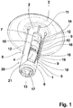
- Fig. 1 shows a perspective view of an expediently made of a hard elastic plastic material embodiment of a device according to the invention.
- the embodiment according to Fig. 1 has an elongate outer part 1, in which in a head sleeve 2 of circumferentially closed hollow cylinder-like shape as a cover assembly, an elastically deformable curved plate-like cover 3 is formed.
- the outer part 1 has two opposing outer wall webs 4, 5, which extend from the cover 3 remote from the end of the head sleeve 2 away in the direction of a researcherhülse 6 of correspondingly the head sleeve 2 of circumferentially closed hollow cylinder-like shape.
- each outer wall web 4 On the radially inward-facing side of each outer wall web 4, 5 is formed in each case one of a plurality of inner teeth 9 formednchteil leopard poetic 10.
- short tolerance compensation ribs 11 or long tolerance compensation ribs 12 are expediently formed on the head sleeve 2 and on the outer wall webs 4, extending in the longitudinal direction with a radial projection over the head sleeve 2 and in the case of the long tolerance compensation ribs 12 over the outer wall webs 4, 5 extend away from the cover 3 in the direction of the foot sleeve 6.
- the embodiment according to Fig. 1 Furthermore, it has an elongate inner part 13, which is arranged displaceable in the longitudinal direction and substantially free of play in the interior of the outer part 1 enclosed by the head sleeve 2, the outer wall webs 4, 5 and the foot sleeve 6.
- the inner part 13 has a substantially hollow-cylinder-like shape and is formed with a circumferentially closed mounting tool engagement sleeve 14, of which in Longitudinal two opposing inner wall webs 15, 16 extend away.
- the inner wall webs 15, 16 are connected at their ends facing away from the mounting tool engagement sleeve 14 with a circumferentially closed end sleeve 17 of the inner part 13.
- each inner wall web 15, 16 there is provided a number of inner teeth tooth structure 19 formed by outer teeth 18, the inner tooth structures 19 being made complementary to the outer tooth structures 10.
- the inner part 13 has two rear handle arms 20, 21, which are integrally formed on the end sleeve 17 and extending through the Wandfreimachitch 7, 8 in the direction of the Abdeckprocesses 3 obliquely radially outwardly and over the outer circumference of the outer part 1 protruding.
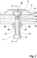
- Fig. 2 shows the embodiment according to Fig. 1 in a first sectional view in a final assembly arrangement when connecting a thin first element 22 arranged at the edge, a thick second element 23 arranged at the edge and a third element 24 of intermediate thickness lying between the first element 22 and the second element 23. From the illustration according to Fig. 2 can be seen that in this final assembly arrangement of the cover 3 rests on the third element 24 remote from the outside of the first element 22, while the rear handle arms 20, 21 formed Hintergriff vom 25 abut the third element 24 remote from the outside of the second element 23. As a result, the elements 22, 23, 24 are firmly connected.
- FIG. 2 To take the in Fig. 2 was shown starting from the in Fig. 1 shown delivery arrangement in Fig. 2 not shown, engageable with a trained in a certain rotational position into engagement with a mounting tool engagement sleeve 14, radially inwardly projecting engagement rib 26
- Rear engagement structure formed mounting pin inserted into the mounting tool engagement sleeve 14, rotated for engagement with the engagement rib 26 and pulled out again until the final mounting arrangement according to Fig. 2 is reached. This is then taken when a predetermined pull-out force releases the mounting pin from engagement with the engagement rib 26.
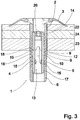
- Fig. 3 shows in a second sectional view taken along the line III-III of Fig. 2 the embodiment according to Fig. 1 in the final assembly according to Fig. 2 , Out Fig. 3
- each internal tooth structure 19 formed with three outer teeth 18 on one inner wall web 15, 16 engages the opposite outer tooth structure 10 formed on each outer wall web 4, 5 in its middle region, as shown schematically in the head sleeve 2 arched in the direction of the foot sleeve 6 cover 3 with a certain bias on the first element 22 rests.
- the curvature of the Abdecktapes 3 is set up so that between two discrete latching steps between the outer tooth structure 10 and the inner teeth tooth structure 19, a continuous compensation in the total thickness of the elements 22, 23, 24 is ensured.
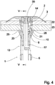
- Fig. 4 shows in a first sectional view as shown in FIG Fig. 2 the embodiment according to Fig. 1 in a further final assembly arrangement when connecting now only a first element 22 and a second element 23, which has a smaller overall thickness than that in Fig. 2 and Fig. 3 shown composite of a total of three elements 22, 23, 24 have.
- Out Fig. 4 It can be seen that in the further final assembly arrangement, the inner part 13 relative to the final assembly arrangement according to Fig. 2 and Fig. 3 with its end sleeve 17 is further spaced from the foot sleeve 6, while the mounting tool engaging sleeve 14 is completely enclosed by the head sleeve 2 and the cover 3.
- Fig. 5 shows in a sectional view taken along the line VV of Fig. 4 the further final assembly according to Fig. 4 , Out Fig. 5 is clear, in the further final assembly arrangement, which is at the same time a minimal thickness final assembly arrangement, the three outer teeth 18 of the inner partial tooth structure 19 formed on the inner wall webs 15, 16 engage with the three inner teeth 9 of the inner toothed teeth 9 closest to the head sleeve 2 of the outer tooth structure 10 formed on the outer wall webs 4, 5.
- the covering screen 3 expediently continues to exert a certain pressure force on the first element 22 facing it in order to ensure a play-free hold of the device according to the invention.
Landscapes
- Engineering & Computer Science (AREA)
- General Engineering & Computer Science (AREA)
- Mechanical Engineering (AREA)
- Component Parts Of Construction Machinery (AREA)
- Orthopedics, Nursing, And Contraception (AREA)
- Golf Clubs (AREA)
Claims (8)
- Dispositif pour assurer une liaison d'assemblage d'au moins deux éléments (22, 23, 24), comprenant une partie extérieure (1), une partie intérieure (13), qui peut coulisser par rapport à la partie extérieure (1) dans une direction longitudinale, et sur laquelle est réalisée une structure dentée de partie intérieure (19) dirigée radialement vers l'extérieur, le dispositif comprenant également des bras de retenue arrière (20, 21) destinés à venir en prise derrière un élément (23), et un agencement de recouvrement (3) à l'opposé des bras de retenue arrière (20, 21), dispositif
dans lequel l'agencement de recouvrement (3) est réalisé seul sur une douille de tête (2) de la partie extérieure (1),
dans lequel les bras de retenue arrière (20, 21) sont réalisés sur la partie intérieure (13),
dans lequel la partie extérieure (1) présente pour chaque bras de retenue arrière (20, 21), un dégagement de paroi (7, 8) à travers lequel passe le bras de retenue arrière (20, 21) respectivement correspondant, et dans lequel la partie extérieure (1) présente une structure dentée de partie extérieure (10), qui est dirigée radialement vers l'intérieur, et est en prise avec la structure dentée de partie intérieure (19) dans l'ensemble à l'état de montage final,
caractérisé en ce que la partie intérieure (13) comporte une douille de venue en prise d'outil de montage (14), qui dispose d'une structure de venue en prise (26) qui résiste jusqu'à une force d'extraction prédéterminée. - Dispositif selon la revendication 1, caractérisé en ce que la structure dentée de partie intérieure (19) est réalisée sur des nervures de paroi intérieure (15, 16) se situant entre les bras de retenue arrière (20, 21).
- Dispositif selon la revendication 2, caractérisé en ce que chaque nervure de paroi intérieure (15, 16) est reliée, par une extrémité, à la douille de venue en prise d'outil de montage (14), et par l'autre extrémité, à une douille d'extrémité (17) située à l'opposé de la douille de venue en prise d'outil de montage (14).
- Dispositif selon l'une des revendications 1 à 3,
caractérisé en ce que la structure dentée de partie extérieure (10) s'étend, dans la direction longitudinale, sur une distance plus grande que la structure dentée de partie intérieure (19). - Dispositif selon l'une des revendications 1 à 4,
caractérisé en ce que la structure dentée de partie extérieure (10) est réalisée sur des nervures de paroi extérieure (4, 5) se situant entre les dégagements de paroi (7, 8). - Dispositif selon l'une des revendications 1 à 5,
caractérisé en ce que dans l'ensemble ou chaque ensemble à l'état de montage final, la structure dentée de partie extérieure (10) et la structure dentée de partie intérieure (19) sont en prise réciproque par l'intermédiaire de plusieurs paires de dents intérieures (9) et de dents extérieures (18). - Dispositif selon l'une des revendications 1 à 6,
caractérisé en ce que l'agencement de recouvrement (3) présente en bordure, une configuration bombée en direction des bras de retenue arrière (20, 21), et est déformable de manière élastique. - Dispositif selon l'une des revendications 5 à 7,
caractérisé en ce que les nervures de paroi extérieure (4, 5) sont reliées à une douille de guidage (6) située à l'opposé de la douille de tête (2).
Applications Claiming Priority (2)
| Application Number | Priority Date | Filing Date | Title |
|---|---|---|---|
| DE102012218339.6A DE102012218339A1 (de) | 2012-10-09 | 2012-10-09 | Vorrichtung zum Verbinden von wenigstens zwei Elementen |
| PCT/EP2013/069725 WO2014056714A1 (fr) | 2012-10-09 | 2013-09-23 | Dispositif permettant d'assembler au moins deux éléments |
Publications (2)
| Publication Number | Publication Date |
|---|---|
| EP2906835A1 EP2906835A1 (fr) | 2015-08-19 |
| EP2906835B1 true EP2906835B1 (fr) | 2017-08-30 |
Family
ID=49263300
Family Applications (1)
| Application Number | Title | Priority Date | Filing Date |
|---|---|---|---|
| EP13770658.6A Not-in-force EP2906835B1 (fr) | 2012-10-09 | 2013-09-23 | Dispositif permettant d'assembler au moins deux éléments |
Country Status (4)
| Country | Link |
|---|---|
| EP (1) | EP2906835B1 (fr) |
| DE (1) | DE102012218339A1 (fr) |
| ES (1) | ES2648493T3 (fr) |
| WO (1) | WO2014056714A1 (fr) |
Families Citing this family (2)
| Publication number | Priority date | Publication date | Assignee | Title |
|---|---|---|---|---|
| CH716425A1 (de) * | 2019-07-24 | 2021-01-29 | Laufen Keramik Holding | Befestigungssystem zur Wandbefestigung von Sanitärvorrichtungen. |
| DE102020214127A1 (de) | 2020-11-10 | 2022-05-12 | Springfix-Befestigungstechnik Gesellschaft mit beschränkter Haftung | Vorrichtung zur Befestigung an einem Bauteil sowie ein Verfahren zur Befestigung einer Vorrichtung an einem Bauteil |
Family Cites Families (13)
| Publication number | Priority date | Publication date | Assignee | Title |
|---|---|---|---|---|
| US2502267A (en) * | 1946-03-13 | 1950-03-28 | Robert L Mcpherson | Self-clinching fastener |
| DE3421574A1 (de) * | 1984-06-09 | 1985-12-12 | Messerschmitt-Bölkow-Blohm GmbH, 2800 Bremen | Blindnietartiges verbindungselement |
| JP2727454B2 (ja) * | 1988-06-28 | 1998-03-11 | 株式会社ニフコ | 板の結合クリップ |
| JP4375695B2 (ja) * | 2000-07-21 | 2009-12-02 | 株式会社ニフコ | 部品の取付装置 |
| FR2845741B1 (fr) * | 2002-10-11 | 2005-01-21 | Itw De France | Rivet muni de pattes elastiques |
| JP2005155738A (ja) * | 2003-11-25 | 2005-06-16 | Piolax Inc | クリップ |
| FR2882114B1 (fr) | 2005-02-17 | 2008-06-20 | Raymond Et Cie Soc En Commandi | Rivet metallique a fixation demontable |
| DE102009048441A1 (de) * | 2009-10-07 | 2011-04-28 | Trw Automotive Electronics & Components Gmbh | Verbindungsbaugruppe |
| JP5550894B2 (ja) * | 2009-12-18 | 2014-07-16 | ポップリベット・ファスナー株式会社 | クリップ |
| JP5378251B2 (ja) * | 2010-01-29 | 2013-12-25 | 大和化成工業株式会社 | クリップ |
| DE102010035011A1 (de) * | 2010-08-20 | 2012-02-23 | A. Raymond Et Cie | Vorrichtung zum Halten eines Anbauteiles an einem Trägerteil sowie Anordnung mit einer derartigen Vorrichtung und mit einem Anbauteil |
| US9303672B2 (en) * | 2010-12-14 | 2016-04-05 | Illinois Tool Works Inc. | Rivet fastener |
| JP2012180915A (ja) * | 2011-03-02 | 2012-09-20 | Nifco Inc | クリップ |
-
2012
- 2012-10-09 DE DE102012218339.6A patent/DE102012218339A1/de active Pending
-
2013
- 2013-09-23 EP EP13770658.6A patent/EP2906835B1/fr not_active Not-in-force
- 2013-09-23 ES ES13770658.6T patent/ES2648493T3/es active Active
- 2013-09-23 WO PCT/EP2013/069725 patent/WO2014056714A1/fr not_active Ceased
Non-Patent Citations (1)
| Title |
|---|
| None * |
Also Published As
| Publication number | Publication date |
|---|---|
| DE102012218339A1 (de) | 2014-04-10 |
| EP2906835A1 (fr) | 2015-08-19 |
| ES2648493T3 (es) | 2018-01-03 |
| WO2014056714A1 (fr) | 2014-04-17 |
Similar Documents
| Publication | Publication Date | Title |
|---|---|---|
| EP2123524B1 (fr) | Raclette d'essuie-glace | |
| EP2810829B1 (fr) | Clip de fixation | |
| WO2012113586A1 (fr) | Balai d'essuie-glace et embout | |
| WO2011101207A1 (fr) | Dispositif de fixation | |
| WO2015085994A1 (fr) | Cadre de retenue pour un connecteur par enfichage | |
| EP3660339A1 (fr) | Dispositif de compensation de tolérance | |
| DE102013110866A1 (de) | Kapazitive Sensoranordnung eines Kraftfahrzeugs | |
| DE2541105A1 (de) | Befestigungselement | |
| DE102008059827B4 (de) | Gleitschuh für ein Schaltelement einer Schalteinrichtung und Schaltelement mit einem solchen Gleitschuh | |
| DE202013103271U1 (de) | Innenflächenseitig vertiefte Kappenanordnung und Reißverschluss-Schieber | |
| EP2592965B1 (fr) | Tiroir avec deux panneaux latéraux et unpanneu arrière | |
| EP2906835B1 (fr) | Dispositif permettant d'assembler au moins deux éléments | |
| DE102019216483B4 (de) | Zierleiste und Steckverbindung für eine Kraftfahrzeugkarosserie | |
| DE102007004065B4 (de) | Stecker | |
| DE102011079131A1 (de) | Wischblattadaptervorrichtung | |
| EP2281122B1 (fr) | Pince de fixation et dispositif présentant une pince de fixation et un composant associé | |
| DE102014112889A1 (de) | Dichtstopfen | |
| DE102006061703A1 (de) | Verbindungsanordnung | |
| DE202010004995U1 (de) | Befestiger zur Befestigung eines ersten Bauteils an einem zweiten Bauteil | |
| EP3116766B1 (fr) | Groupe modulaire pour un véhicule automobile et procédé servant à relier une partie de carrosserie à un spoiler | |
| DE102008025093B4 (de) | Sicherheitsgurt-Umlenkelement mit einstückigem Verkleidungsteil | |
| DE2847978C2 (de) | Wischvorrichtung für Scheiben von Kraftfahrzeugen | |
| DE102016212809B4 (de) | Scharnieranordnung sowie hiermit ausgestattetes Kraftfahrzeug | |
| DE2608605C3 (de) | Wischvorrichtung für Scheiben von Kraftfahrzeugen | |
| DE102009009883A1 (de) | Verbindungsanordnung zum Verbinden eines Anbauteils mit einem Trägerteil |
Legal Events
| Date | Code | Title | Description |
|---|---|---|---|
| PUAI | Public reference made under article 153(3) epc to a published international application that has entered the european phase |
Free format text: ORIGINAL CODE: 0009012 |
|
| 17P | Request for examination filed |
Effective date: 20150421 |
|
| AK | Designated contracting states |
Kind code of ref document: A1 Designated state(s): AL AT BE BG CH CY CZ DE DK EE ES FI FR GB GR HR HU IE IS IT LI LT LU LV MC MK MT NL NO PL PT RO RS SE SI SK SM TR |
|
| AX | Request for extension of the european patent |
Extension state: BA ME |
|
| DAX | Request for extension of the european patent (deleted) | ||
| GRAP | Despatch of communication of intention to grant a patent |
Free format text: ORIGINAL CODE: EPIDOSNIGR1 |
|
| STAA | Information on the status of an ep patent application or granted ep patent |
Free format text: STATUS: GRANT OF PATENT IS INTENDED |
|
| INTG | Intention to grant announced |
Effective date: 20170314 |
|
| GRAS | Grant fee paid |
Free format text: ORIGINAL CODE: EPIDOSNIGR3 |
|
| GRAA | (expected) grant |
Free format text: ORIGINAL CODE: 0009210 |
|
| STAA | Information on the status of an ep patent application or granted ep patent |
Free format text: STATUS: THE PATENT HAS BEEN GRANTED |
|
| AK | Designated contracting states |
Kind code of ref document: B1 Designated state(s): AL AT BE BG CH CY CZ DE DK EE ES FI FR GB GR HR HU IE IS IT LI LT LU LV MC MK MT NL NO PL PT RO RS SE SI SK SM TR |
|
| REG | Reference to a national code |
Ref country code: GB Ref legal event code: FG4D Free format text: NOT ENGLISH |
|
| REG | Reference to a national code |
Ref country code: CH Ref legal event code: EP |
|
| REG | Reference to a national code |
Ref country code: AT Ref legal event code: REF Ref document number: 923850 Country of ref document: AT Kind code of ref document: T Effective date: 20170915 |
|
| REG | Reference to a national code |
Ref country code: IE Ref legal event code: FG4D Free format text: LANGUAGE OF EP DOCUMENT: GERMAN |
|
| REG | Reference to a national code |
Ref country code: FR Ref legal event code: PLFP Year of fee payment: 5 |
|
| REG | Reference to a national code |
Ref country code: DE Ref legal event code: R096 Ref document number: 502013008220 Country of ref document: DE |
|
| REG | Reference to a national code |
Ref country code: ES Ref legal event code: FG2A Ref document number: 2648493 Country of ref document: ES Kind code of ref document: T3 Effective date: 20180103 Ref country code: NL Ref legal event code: MP Effective date: 20170830 |
|
| REG | Reference to a national code |
Ref country code: LT Ref legal event code: MG4D |
|
| PG25 | Lapsed in a contracting state [announced via postgrant information from national office to epo] |
Ref country code: FI Free format text: LAPSE BECAUSE OF FAILURE TO SUBMIT A TRANSLATION OF THE DESCRIPTION OR TO PAY THE FEE WITHIN THE PRESCRIBED TIME-LIMIT Effective date: 20170830 Ref country code: LT Free format text: LAPSE BECAUSE OF FAILURE TO SUBMIT A TRANSLATION OF THE DESCRIPTION OR TO PAY THE FEE WITHIN THE PRESCRIBED TIME-LIMIT Effective date: 20170830 Ref country code: SE Free format text: LAPSE BECAUSE OF FAILURE TO SUBMIT A TRANSLATION OF THE DESCRIPTION OR TO PAY THE FEE WITHIN THE PRESCRIBED TIME-LIMIT Effective date: 20170830 Ref country code: HR Free format text: LAPSE BECAUSE OF FAILURE TO SUBMIT A TRANSLATION OF THE DESCRIPTION OR TO PAY THE FEE WITHIN THE PRESCRIBED TIME-LIMIT Effective date: 20170830 Ref country code: NO Free format text: LAPSE BECAUSE OF FAILURE TO SUBMIT A TRANSLATION OF THE DESCRIPTION OR TO PAY THE FEE WITHIN THE PRESCRIBED TIME-LIMIT Effective date: 20171130 |
|
| PG25 | Lapsed in a contracting state [announced via postgrant information from national office to epo] |
Ref country code: LV Free format text: LAPSE BECAUSE OF FAILURE TO SUBMIT A TRANSLATION OF THE DESCRIPTION OR TO PAY THE FEE WITHIN THE PRESCRIBED TIME-LIMIT Effective date: 20170830 Ref country code: RS Free format text: LAPSE BECAUSE OF FAILURE TO SUBMIT A TRANSLATION OF THE DESCRIPTION OR TO PAY THE FEE WITHIN THE PRESCRIBED TIME-LIMIT Effective date: 20170830 Ref country code: IS Free format text: LAPSE BECAUSE OF FAILURE TO SUBMIT A TRANSLATION OF THE DESCRIPTION OR TO PAY THE FEE WITHIN THE PRESCRIBED TIME-LIMIT Effective date: 20171230 Ref country code: BG Free format text: LAPSE BECAUSE OF FAILURE TO SUBMIT A TRANSLATION OF THE DESCRIPTION OR TO PAY THE FEE WITHIN THE PRESCRIBED TIME-LIMIT Effective date: 20171130 Ref country code: GR Free format text: LAPSE BECAUSE OF FAILURE TO SUBMIT A TRANSLATION OF THE DESCRIPTION OR TO PAY THE FEE WITHIN THE PRESCRIBED TIME-LIMIT Effective date: 20171201 |
|
| PG25 | Lapsed in a contracting state [announced via postgrant information from national office to epo] |
Ref country code: NL Free format text: LAPSE BECAUSE OF FAILURE TO SUBMIT A TRANSLATION OF THE DESCRIPTION OR TO PAY THE FEE WITHIN THE PRESCRIBED TIME-LIMIT Effective date: 20170830 |
|
| PG25 | Lapsed in a contracting state [announced via postgrant information from national office to epo] |
Ref country code: RO Free format text: LAPSE BECAUSE OF FAILURE TO SUBMIT A TRANSLATION OF THE DESCRIPTION OR TO PAY THE FEE WITHIN THE PRESCRIBED TIME-LIMIT Effective date: 20170830 Ref country code: DK Free format text: LAPSE BECAUSE OF FAILURE TO SUBMIT A TRANSLATION OF THE DESCRIPTION OR TO PAY THE FEE WITHIN THE PRESCRIBED TIME-LIMIT Effective date: 20170830 Ref country code: PL Free format text: LAPSE BECAUSE OF FAILURE TO SUBMIT A TRANSLATION OF THE DESCRIPTION OR TO PAY THE FEE WITHIN THE PRESCRIBED TIME-LIMIT Effective date: 20170830 |
|
| REG | Reference to a national code |
Ref country code: CH Ref legal event code: PL |
|
| PG25 | Lapsed in a contracting state [announced via postgrant information from national office to epo] |
Ref country code: SK Free format text: LAPSE BECAUSE OF FAILURE TO SUBMIT A TRANSLATION OF THE DESCRIPTION OR TO PAY THE FEE WITHIN THE PRESCRIBED TIME-LIMIT Effective date: 20170830 Ref country code: SM Free format text: LAPSE BECAUSE OF FAILURE TO SUBMIT A TRANSLATION OF THE DESCRIPTION OR TO PAY THE FEE WITHIN THE PRESCRIBED TIME-LIMIT Effective date: 20170830 Ref country code: EE Free format text: LAPSE BECAUSE OF FAILURE TO SUBMIT A TRANSLATION OF THE DESCRIPTION OR TO PAY THE FEE WITHIN THE PRESCRIBED TIME-LIMIT Effective date: 20170830 Ref country code: MC Free format text: LAPSE BECAUSE OF FAILURE TO SUBMIT A TRANSLATION OF THE DESCRIPTION OR TO PAY THE FEE WITHIN THE PRESCRIBED TIME-LIMIT Effective date: 20170830 |
|
| REG | Reference to a national code |
Ref country code: DE Ref legal event code: R097 Ref document number: 502013008220 Country of ref document: DE |
|
| REG | Reference to a national code |
Ref country code: IE Ref legal event code: MM4A |
|
| REG | Reference to a national code |
Ref country code: BE Ref legal event code: MM Effective date: 20170930 |
|
| PG25 | Lapsed in a contracting state [announced via postgrant information from national office to epo] |
Ref country code: LU Free format text: LAPSE BECAUSE OF NON-PAYMENT OF DUE FEES Effective date: 20170923 |
|
| PLBE | No opposition filed within time limit |
Free format text: ORIGINAL CODE: 0009261 |
|
| STAA | Information on the status of an ep patent application or granted ep patent |
Free format text: STATUS: NO OPPOSITION FILED WITHIN TIME LIMIT |
|
| GBPC | Gb: european patent ceased through non-payment of renewal fee |
Effective date: 20171130 |
|
| PG25 | Lapsed in a contracting state [announced via postgrant information from national office to epo] |
Ref country code: IE Free format text: LAPSE BECAUSE OF NON-PAYMENT OF DUE FEES Effective date: 20170923 Ref country code: CH Free format text: LAPSE BECAUSE OF NON-PAYMENT OF DUE FEES Effective date: 20170930 Ref country code: LI Free format text: LAPSE BECAUSE OF NON-PAYMENT OF DUE FEES Effective date: 20170930 |
|
| 26N | No opposition filed |
Effective date: 20180531 |
|
| PG25 | Lapsed in a contracting state [announced via postgrant information from national office to epo] |
Ref country code: SI Free format text: LAPSE BECAUSE OF FAILURE TO SUBMIT A TRANSLATION OF THE DESCRIPTION OR TO PAY THE FEE WITHIN THE PRESCRIBED TIME-LIMIT Effective date: 20170830 Ref country code: BE Free format text: LAPSE BECAUSE OF NON-PAYMENT OF DUE FEES Effective date: 20170930 |
|
| REG | Reference to a national code |
Ref country code: FR Ref legal event code: PLFP Year of fee payment: 6 |
|
| PG25 | Lapsed in a contracting state [announced via postgrant information from national office to epo] |
Ref country code: MT Free format text: LAPSE BECAUSE OF FAILURE TO SUBMIT A TRANSLATION OF THE DESCRIPTION OR TO PAY THE FEE WITHIN THE PRESCRIBED TIME-LIMIT Effective date: 20170830 |
|
| PG25 | Lapsed in a contracting state [announced via postgrant information from national office to epo] |
Ref country code: GB Free format text: LAPSE BECAUSE OF NON-PAYMENT OF DUE FEES Effective date: 20171130 |
|
| PG25 | Lapsed in a contracting state [announced via postgrant information from national office to epo] |
Ref country code: HU Free format text: LAPSE BECAUSE OF FAILURE TO SUBMIT A TRANSLATION OF THE DESCRIPTION OR TO PAY THE FEE WITHIN THE PRESCRIBED TIME-LIMIT; INVALID AB INITIO Effective date: 20130923 |
|
| PG25 | Lapsed in a contracting state [announced via postgrant information from national office to epo] |
Ref country code: CY Free format text: LAPSE BECAUSE OF FAILURE TO SUBMIT A TRANSLATION OF THE DESCRIPTION OR TO PAY THE FEE WITHIN THE PRESCRIBED TIME-LIMIT Effective date: 20170830 |
|
| REG | Reference to a national code |
Ref country code: AT Ref legal event code: MM01 Ref document number: 923850 Country of ref document: AT Kind code of ref document: T Effective date: 20180923 |
|
| PG25 | Lapsed in a contracting state [announced via postgrant information from national office to epo] |
Ref country code: MK Free format text: LAPSE BECAUSE OF FAILURE TO SUBMIT A TRANSLATION OF THE DESCRIPTION OR TO PAY THE FEE WITHIN THE PRESCRIBED TIME-LIMIT Effective date: 20170830 |
|
| PG25 | Lapsed in a contracting state [announced via postgrant information from national office to epo] |
Ref country code: AT Free format text: LAPSE BECAUSE OF NON-PAYMENT OF DUE FEES Effective date: 20180923 |
|
| PG25 | Lapsed in a contracting state [announced via postgrant information from national office to epo] |
Ref country code: TR Free format text: LAPSE BECAUSE OF FAILURE TO SUBMIT A TRANSLATION OF THE DESCRIPTION OR TO PAY THE FEE WITHIN THE PRESCRIBED TIME-LIMIT Effective date: 20170830 |
|
| PG25 | Lapsed in a contracting state [announced via postgrant information from national office to epo] |
Ref country code: PT Free format text: LAPSE BECAUSE OF FAILURE TO SUBMIT A TRANSLATION OF THE DESCRIPTION OR TO PAY THE FEE WITHIN THE PRESCRIBED TIME-LIMIT Effective date: 20170830 |
|
| PG25 | Lapsed in a contracting state [announced via postgrant information from national office to epo] |
Ref country code: AL Free format text: LAPSE BECAUSE OF FAILURE TO SUBMIT A TRANSLATION OF THE DESCRIPTION OR TO PAY THE FEE WITHIN THE PRESCRIBED TIME-LIMIT Effective date: 20170830 |
|
| PGFP | Annual fee paid to national office [announced via postgrant information from national office to epo] |
Ref country code: FR Payment date: 20210921 Year of fee payment: 9 Ref country code: CZ Payment date: 20210922 Year of fee payment: 9 Ref country code: IT Payment date: 20210922 Year of fee payment: 9 |
|
| PGFP | Annual fee paid to national office [announced via postgrant information from national office to epo] |
Ref country code: DE Payment date: 20210920 Year of fee payment: 9 |
|
| PGFP | Annual fee paid to national office [announced via postgrant information from national office to epo] |
Ref country code: ES Payment date: 20211125 Year of fee payment: 9 |
|
| REG | Reference to a national code |
Ref country code: DE Ref legal event code: R119 Ref document number: 502013008220 Country of ref document: DE |
|
| PG25 | Lapsed in a contracting state [announced via postgrant information from national office to epo] |
Ref country code: CZ Free format text: LAPSE BECAUSE OF NON-PAYMENT OF DUE FEES Effective date: 20220923 |
|
| PG25 | Lapsed in a contracting state [announced via postgrant information from national office to epo] |
Ref country code: FR Free format text: LAPSE BECAUSE OF NON-PAYMENT OF DUE FEES Effective date: 20220930 Ref country code: DE Free format text: LAPSE BECAUSE OF NON-PAYMENT OF DUE FEES Effective date: 20230401 |
|
| PG25 | Lapsed in a contracting state [announced via postgrant information from national office to epo] |
Ref country code: IT Free format text: LAPSE BECAUSE OF NON-PAYMENT OF DUE FEES Effective date: 20220923 |
|
| REG | Reference to a national code |
Ref country code: ES Ref legal event code: FD2A Effective date: 20231102 |
|
| PG25 | Lapsed in a contracting state [announced via postgrant information from national office to epo] |
Ref country code: ES Free format text: LAPSE BECAUSE OF NON-PAYMENT OF DUE FEES Effective date: 20220924 |
|
| PG25 | Lapsed in a contracting state [announced via postgrant information from national office to epo] |
Ref country code: ES Free format text: LAPSE BECAUSE OF NON-PAYMENT OF DUE FEES Effective date: 20220924 |