EP2906818B1 - Wind turbine on a spar floating structure with two rotors on a v-shaped support structure - Google Patents
Wind turbine on a spar floating structure with two rotors on a v-shaped support structure Download PDFInfo
- Publication number
- EP2906818B1 EP2906818B1 EP13789718.7A EP13789718A EP2906818B1 EP 2906818 B1 EP2906818 B1 EP 2906818B1 EP 13789718 A EP13789718 A EP 13789718A EP 2906818 B1 EP2906818 B1 EP 2906818B1
- Authority
- EP
- European Patent Office
- Prior art keywords
- wind turbine
- rotors
- twin
- turbine according
- rotor
- Prior art date
- Legal status (The legal status is an assumption and is not a legal conclusion. Google has not performed a legal analysis and makes no representation as to the accuracy of the status listed.)
- Active
Links
Images

Classifications
-
- F—MECHANICAL ENGINEERING; LIGHTING; HEATING; WEAPONS; BLASTING
- F03—MACHINES OR ENGINES FOR LIQUIDS; WIND, SPRING, OR WEIGHT MOTORS; PRODUCING MECHANICAL POWER OR A REACTIVE PROPULSIVE THRUST, NOT OTHERWISE PROVIDED FOR
- F03D—WIND MOTORS
- F03D1/00—Wind motors with rotation axis substantially parallel to the air flow entering the rotor
- F03D1/02—Wind motors with rotation axis substantially parallel to the air flow entering the rotor having a plurality of rotors
-
- B—PERFORMING OPERATIONS; TRANSPORTING
- B63—SHIPS OR OTHER WATERBORNE VESSELS; RELATED EQUIPMENT
- B63B—SHIPS OR OTHER WATERBORNE VESSELS; EQUIPMENT FOR SHIPPING
- B63B35/00—Vessels or similar floating structures specially adapted for specific purposes and not otherwise provided for
- B63B35/44—Floating buildings, stores, drilling platforms, or workshops, e.g. carrying water-oil separating devices
-
- F—MECHANICAL ENGINEERING; LIGHTING; HEATING; WEAPONS; BLASTING
- F03—MACHINES OR ENGINES FOR LIQUIDS; WIND, SPRING, OR WEIGHT MOTORS; PRODUCING MECHANICAL POWER OR A REACTIVE PROPULSIVE THRUST, NOT OTHERWISE PROVIDED FOR
- F03D—WIND MOTORS
- F03D13/00—Assembly, mounting or commissioning of wind motors; Arrangements specially adapted for transporting wind motor components
- F03D13/20—Arrangements for mounting or supporting wind motors; Masts or towers for wind motors
- F03D13/25—Arrangements for mounting or supporting wind motors; Masts or towers for wind motors specially adapted for offshore installation
-
- F—MECHANICAL ENGINEERING; LIGHTING; HEATING; WEAPONS; BLASTING
- F03—MACHINES OR ENGINES FOR LIQUIDS; WIND, SPRING, OR WEIGHT MOTORS; PRODUCING MECHANICAL POWER OR A REACTIVE PROPULSIVE THRUST, NOT OTHERWISE PROVIDED FOR
- F03D—WIND MOTORS
- F03D80/00—Details, components or accessories not provided for in groups F03D1/00 - F03D17/00
- F03D80/80—Arrangement of components within nacelles or towers
- F03D80/82—Arrangement of components within nacelles or towers of electrical components
- F03D80/85—Cabling
-
- B—PERFORMING OPERATIONS; TRANSPORTING
- B63—SHIPS OR OTHER WATERBORNE VESSELS; RELATED EQUIPMENT
- B63B—SHIPS OR OTHER WATERBORNE VESSELS; EQUIPMENT FOR SHIPPING
- B63B35/00—Vessels or similar floating structures specially adapted for specific purposes and not otherwise provided for
- B63B35/44—Floating buildings, stores, drilling platforms, or workshops, e.g. carrying water-oil separating devices
- B63B2035/442—Spar-type semi-submersible structures, i.e. shaped as single slender, e.g. substantially cylindrical or trussed vertical bodies
-
- B—PERFORMING OPERATIONS; TRANSPORTING
- B63—SHIPS OR OTHER WATERBORNE VESSELS; RELATED EQUIPMENT
- B63B—SHIPS OR OTHER WATERBORNE VESSELS; EQUIPMENT FOR SHIPPING
- B63B35/00—Vessels or similar floating structures specially adapted for specific purposes and not otherwise provided for
- B63B35/44—Floating buildings, stores, drilling platforms, or workshops, e.g. carrying water-oil separating devices
- B63B2035/4433—Floating structures carrying electric power plants
- B63B2035/446—Floating structures carrying electric power plants for converting wind energy into electric energy
-
- F—MECHANICAL ENGINEERING; LIGHTING; HEATING; WEAPONS; BLASTING
- F05—INDEXING SCHEMES RELATING TO ENGINES OR PUMPS IN VARIOUS SUBCLASSES OF CLASSES F01-F04
- F05B—INDEXING SCHEME RELATING TO WIND, SPRING, WEIGHT, INERTIA OR LIKE MOTORS, TO MACHINES OR ENGINES FOR LIQUIDS COVERED BY SUBCLASSES F03B, F03D AND F03G
- F05B2240/00—Components
- F05B2240/90—Mounting on supporting structures or systems
- F05B2240/91—Mounting on supporting structures or systems on a stationary structure
- F05B2240/917—Mounting on supporting structures or systems on a stationary structure attached to cables
-
- F—MECHANICAL ENGINEERING; LIGHTING; HEATING; WEAPONS; BLASTING
- F05—INDEXING SCHEMES RELATING TO ENGINES OR PUMPS IN VARIOUS SUBCLASSES OF CLASSES F01-F04
- F05B—INDEXING SCHEME RELATING TO WIND, SPRING, WEIGHT, INERTIA OR LIKE MOTORS, TO MACHINES OR ENGINES FOR LIQUIDS COVERED BY SUBCLASSES F03B, F03D AND F03G
- F05B2240/00—Components
- F05B2240/90—Mounting on supporting structures or systems
- F05B2240/93—Mounting on supporting structures or systems on a structure floating on a liquid surface
-
- F—MECHANICAL ENGINEERING; LIGHTING; HEATING; WEAPONS; BLASTING
- F05—INDEXING SCHEMES RELATING TO ENGINES OR PUMPS IN VARIOUS SUBCLASSES OF CLASSES F01-F04
- F05B—INDEXING SCHEME RELATING TO WIND, SPRING, WEIGHT, INERTIA OR LIKE MOTORS, TO MACHINES OR ENGINES FOR LIQUIDS COVERED BY SUBCLASSES F03B, F03D AND F03G
- F05B2240/00—Components
- F05B2240/90—Mounting on supporting structures or systems
- F05B2240/95—Mounting on supporting structures or systems offshore
-
- F—MECHANICAL ENGINEERING; LIGHTING; HEATING; WEAPONS; BLASTING
- F05—INDEXING SCHEMES RELATING TO ENGINES OR PUMPS IN VARIOUS SUBCLASSES OF CLASSES F01-F04
- F05B—INDEXING SCHEME RELATING TO WIND, SPRING, WEIGHT, INERTIA OR LIKE MOTORS, TO MACHINES OR ENGINES FOR LIQUIDS COVERED BY SUBCLASSES F03B, F03D AND F03G
- F05B2260/00—Function
- F05B2260/70—Adjusting of angle of incidence or attack of rotating blades
-
- Y—GENERAL TAGGING OF NEW TECHNOLOGICAL DEVELOPMENTS; GENERAL TAGGING OF CROSS-SECTIONAL TECHNOLOGIES SPANNING OVER SEVERAL SECTIONS OF THE IPC; TECHNICAL SUBJECTS COVERED BY FORMER USPC CROSS-REFERENCE ART COLLECTIONS [XRACs] AND DIGESTS
- Y02—TECHNOLOGIES OR APPLICATIONS FOR MITIGATION OR ADAPTATION AGAINST CLIMATE CHANGE
- Y02E—REDUCTION OF GREENHOUSE GAS [GHG] EMISSIONS, RELATED TO ENERGY GENERATION, TRANSMISSION OR DISTRIBUTION
- Y02E10/00—Energy generation through renewable energy sources
- Y02E10/70—Wind energy
- Y02E10/72—Wind turbines with rotation axis in wind direction
-
- Y—GENERAL TAGGING OF NEW TECHNOLOGICAL DEVELOPMENTS; GENERAL TAGGING OF CROSS-SECTIONAL TECHNOLOGIES SPANNING OVER SEVERAL SECTIONS OF THE IPC; TECHNICAL SUBJECTS COVERED BY FORMER USPC CROSS-REFERENCE ART COLLECTIONS [XRACs] AND DIGESTS
- Y02—TECHNOLOGIES OR APPLICATIONS FOR MITIGATION OR ADAPTATION AGAINST CLIMATE CHANGE
- Y02E—REDUCTION OF GREENHOUSE GAS [GHG] EMISSIONS, RELATED TO ENERGY GENERATION, TRANSMISSION OR DISTRIBUTION
- Y02E10/00—Energy generation through renewable energy sources
- Y02E10/70—Wind energy
- Y02E10/727—Offshore wind turbines
Definitions
- the invention relates to the construction of wind power plants, intended to be exploited at sea, where the wind is on average stronger and more regular, and where the neighborhood constraints are the least penalizing.
- the disadvantage for the TLP is that the cost corresponding to the structure and the anchors is important and hardly compatible with its function.
- Mr. Torr Todman ( GB2443886 ) describes a "T" birotor architecture.
- the invention of William Heronemus ( US2003 / 168864 ) describes a "V" trirotor architecture where the rotors are placed facing the wind on a floating structure equipped with a flotation system and a ballast.
- Alexandroff ( FR2752443 and EP0761964 ) has a "V” architecture, with a “wind” and “downwind” wind turbine.
- the French patent application FR2938306 In particular, it presents a birotor wind turbine generator on a floating structure of the "floating tense" type.
- a disadvantage of this technique is related to the floating structure type "floating tension". Indeed, according to this technique, the floating structure is maintained in position in the sea by one or more tensioned anchor lines. The distance between the ground and the floating structure, slightly cast, is therefore fixed. As a result, the floating structure can not naturally follow the movement of the waves, and it is necessary to raise the rotors relative to the sea level to avoid immersion in large waves. Moreover, such a structure requires the use of anchoring and relatively expensive anchoring lines.
- the invention relates to a particular architecture of floating wind turbine to improve the technologies known to date.
- the improvements concern particularly the general architecture of the whole, as well as the combination of particular devices.
- the invention relates to a "V" birotor aerogenerator on a floating structure.
- the floating structure is of the SPAR type (in English "Single Point Anchor Reservoir"), comprising a central shaft provided with a ballast in its lower part (also called float), and pivoting on itself in order to orient its upper part carrying both rotors facing the wind.
- the wind turbine comprises at least three stays, including an upper cable connecting the two rotors between them and two lower cables each connecting one of the rotors to the central shaft.
- the invention therefore proposes a new wind turbine comprising two wind rotors mounted on a "V" structure, itself mounted on a floating structure of the SPAR type.
- Such a floating structure SPAR type is conventionally formed of a central shaft, or float, provided with a ballast in its lower part, and is held in position by non-tensioned anchor lines.
- a structure floats like a plug, and can follow the natural movement of the waves.
- the "SPAR” type architecture has major hydrodynamic advantages with a very soft stability, guaranteeing slow movements decreasing sensitivity to waves and waves, especially for sensitive electromechanical parts (whose height at above the body of water already aggravates the acceleration due to shocks and movements in the sea).
- such a structure is more economical and durable than a "floating floating" type structure, and allows implantation on all types of bottom (rocks, sand, silt).
- the rotors are naturally oriented according to the invention, possibly by acting on their pitch, and require no reaction from the support, that they do not tend to rotate in the opposite direction of the aerial.
- a guying according to the invention makes it possible to take up the forces in the transverse plane and to balance the system.
- the guying includes exactly three stays or cables, including an upper cable directly connecting the two rotors above the central shaft / mast and two lower cables connected to the central shaft / mast balancing the system.
- the moments in the transverse plane, around the longitudinal axis, are taken up by the guying, an upper cable directly connecting the two rotors at the top of the mast and two lower cables taken up at a leveling ring the system.
- This intrinsically rigid structure can be prestressed to further minimize vibrations. It is aerodynamically advantageous (low drag), and promotes stability by limiting weight in the high.
- an interest of the birotor is to pool the structural elements and anchoring, particularly expensive, and therefore to obtain a lower cost of production compared to a single rotor solution.
- birotor Another interest of the birotor is to be able to "densify" the production of energy, the rotors normally having to be separated by 3 to 5 times their diameter in order to avoid the aerodynamic disturbances emitted downstream of a rotor. It is thus possible according to the invention to produce more electrical power for a given operating area, and therefore to obtain better economic performance.
- Each of the rotors is placed facing the wind, the torque induced by their mass reversal torque to counter the torque generated by the thrust of the wind on the rotors, which advantageously reduces the size of the ballast.
- Another advantage of the proposed aerogenerator is that it allows, thanks to the position of the anchoring lines near the waterline, a simplified maintenance and a decreased inclining moment.
- This invention thus has the remarkable advantage of building at a lower cost a floating wind system naturally oriented and permanently in the wind even in the presence of waves and waves, thus producing more average electrical power. It is thus possible according to the invention to produce more average electrical power for a given operating area, with structures at lower cost.
- the energy (electricity) thus produced can then be conveyed by cable or stored locally, for example after chemical transformation to produce hydrogen, methane, etc.
- the structure of the dead works i.e. the structure located above the water
- which supports the two rotors comprises at least four arrows bars (for example 4, 6 or 8).
- These arrows bars can be metal or composite, and more or less profiled.
- the structure of the dead works that supports the two rotors includes exactly four arrows bars, two for each rotor.
- the structure of the dead works which supports the two rotors thus consists partly of four arrows bars, metal or composite and more or less profiled, two for each rotor, so as to take the bending force around the vertical axes and transverse to the clean mass and the action of the wind on the blades (drag) and the indirect actions of the sea.
- the wind deflector works in traction
- the lee in the wind works in compression.
- the two arrows bars supporting a rotor are tubular, and are positioned in open V, with the tip of the V at the rotor. This makes it possible to improve the aerodynamics of the structure.
- the two rotors are counter-rotating, this characteristic being advantageous because it makes it possible to cancel the gyroscopic forces induced on the structures.
- the system of orientation of the wind turbine by the step playing on the drag of the blades does not require any engine or transmissions inside the central shaft / mast. But above all, acting directly on the aerial, it requires no reaction of the support, that it does not tend to turn in the opposite direction of the aerial, which is taken up by the foundations for the devices founded, or by tethered anchor lines for other floating wind turbines (including floating-tense type).
- Such a pitch orientation system is therefore more suitable for the use of unstretched anchor lines, less expensive and allowing implantation on all types of bottom (rocks, sand, mud).
- each rotor may comprise a blade, two blades, three blades or more.
- the number of blades may be different from one rotor to another.
- each rotor comprises two blades. This allows in particular to reduce the cost of the rotor, and to limit the mass at the top of the structure.
- the rotors may be of the two-blade type. This feature is particularly interesting because it facilitates the horizontal transport of the wind turbine, on land and sea, by a smaller footprint.
- the aerogenerator can be assembled on the ground on a single solid ground, and then transported horizontally to the ground using trolleys to the launching dock.
- the aerogenerator may be transported on the water horizontally, to the place of operation, with the aid of a barge or a transport boat.
- This solution has the advantage of not requiring heavy crane for transportation and assembly of the wind turbine (wind turbine).
- the ballast may consist of recyclable or recycled materials, sand, aggregates, crushed concrete and rubble from construction, etc. This makes it more efficient than a liquid ballast while being environmentally friendly.
- the control of the orientation of the upper part of the assembly from the control of the pitch generates an oscillation of the wind turbine around its vertical axis, alternatively creating a supplement / deficit of wind on one of the rotors.
- This phenomenon of creation of artificial wind or "pumping" makes it possible to increase the efficiency of the wind turbine in light wind.
- the central drum comprises a submerged portion and a non-submerged portion, the non-immersed portion being movable relative to the immersed portion and connected to the portion immersed by an orientation ring, and the lower cables each connect one of the rotors to the movable portion of the central shaft.
- the immersed portion is held in position by the unstretched anchor lines. It can not rotate on itself.
- the non-submerged portion is itself movable, and allows the floating structure to rotate around the central shaft to orient the two rotors as desired, to orient its upper part facing the wind.
- the slewing ring forms a rotary coupling system, located at the base of the "V" of the "V" birotor wind turbine.
- the central shaft is entirely mobile, and is provided with a crown ring to which the anchoring lines are attached.
- the floating structure pivots on itself around a fixed shaft located above the water, in order to orient its upper part facing the wind.
- the invention also relates to a birotor wind turbine as previously described isolated or constituting an offshore wind power plant of any power.
- the general principle of the invention is based on the combination of a "V" birotor wind turbine and a SPAR floating structure, implementing a specific guying.
- the SPAR type floating structure comprising a central shaft provided with a ballast at its lower part, and pivots on itself in order to orient its upper part carrying the two rotors facing the wind.
- an aerogenerator according to the invention comprises at least three stays, including an upper cable connecting the two rotors between them and two lower cables each connecting one of said rotors to the central shaft.
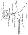
- the central shaft comprises on the one hand a submerged portion 7, comprising the ballast, and a non-immersed portion, also called mast 5.
- the mast is movable relative to the submerged barrel 7 at a ring gear. orientation 6.
- the floating structure is maintained in the water using unstretched anchor lines 8.
- an aerogenerator as illustrated in Figures 1A and 1B comprises two nacelles, each provided with a rotor 1, 2 mounted on a "V" structure.
- the two rotors 1, 2 are each held by two arrows bars, which can be recessed on the top of the profiled mast 5.
- a hinge is provided at the bottom of the arrows bars, so as to they can be folded when transporting the wind turbine. When the wind blows on the blades, the wind deflector works in tension, the lee in the wind works in compression.
- three cables are provided to take the moments in the transverse plane, around the longitudinal axis, and balance the structure.
- An upper cable 3 also called hanger, connects the two rotors.
- Lower cables also called risers, are used to connect each of the rotors to the profiled mast 5.
- the structure can be oriented naturally to orient its upper part (mast 5, rotors 1, 2 and guying 3, 4) facing the wind.
- the central shaft is entirely mobile.
- a crown ring is placed around the barrel, and the anchor lines are connected to this ring.
- the barrel can pivot about its central axis, while being held by the anchor lines connected to the ring.
- the ring rotates in a rail provided on the central shaft.
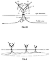
- the figure 2 represents a wind farm consisting of several birotor wind turbines according to the invention.
- wind turbines according to the invention can be used alone, or be part of off-shore wind power plants of all powers, linear or concentrated configurations of the wind farm type.
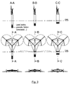
- the figure 3 represents a front view of several configurations of draft (short ballast, long ballast), according to the example described in relation to the Figures 1A and 1B .
- the figure 4 represents the downward orientation of the two nacelles.
- the figure 5 represents the operation of the wind turbine in pumping mode.
Landscapes
- Engineering & Computer Science (AREA)
- Chemical & Material Sciences (AREA)
- Mechanical Engineering (AREA)
- Combustion & Propulsion (AREA)
- Sustainable Energy (AREA)
- Life Sciences & Earth Sciences (AREA)
- Sustainable Development (AREA)
- General Engineering & Computer Science (AREA)
- Architecture (AREA)
- Civil Engineering (AREA)
- Structural Engineering (AREA)
- Ocean & Marine Engineering (AREA)
- Wind Motors (AREA)
Description
L'invention est relative à la construction de centrales électriques éoliennes, destinées à être exploitées en mer, là où le vent est en moyenne plus fort et plus régulier, et là où les contraintes de voisinage sont les moins pénalisantes.The invention relates to the construction of wind power plants, intended to be exploited at sea, where the wind is on average stronger and more regular, and where the neighborhood constraints are the least penalizing.
Des solutions d'éoliennes en mer fixées sur des fondations au sol existent déjà et permettent une exploitation jusqu'à environ 50m de profondeur.Solutions of offshore wind turbines fixed on ground foundations already exist and allow exploitation up to about 50m deep.
Compte tenu des caractéristiques géographiques des pays (dont la France) dont les côtes présentent rapidement des fonds de profondeur supérieurs à 50m, il est judicieux de pouvoir disposer d'éoliennes flottantes.Given the geographical characteristics of the countries (including France) whose coasts quickly have depths deeper than 50m, it is wise to have floating wind turbines.
Plusieurs types d'éoliennes flottantes sont actuellement à l'étude ou en développement :
- Type Barge flottante ou multi-flotteurs :
- L'éolienne est fixée sur une plate-forme semblable à une barge flottante ou bien sur une plate forme multi-flotteurs, d'où un volume de flottaison essentiellement en surface.
- L'ensemble est ancré au fond marin par des ancrages souples.
- Type Floating Barge or Multi-Floats:
- The wind turbine is fixed on a platform similar to a floating barge or on a multi-float platform, resulting in a floatation volume essentially on the surface.
- The set is anchored to the seabed by flexible anchors.
L'inconvénient de ce type d'architecture est une grande sensibilité aux vagues et à la houle, induisant des efforts dynamiques importants sur les nacelles éoliennes, incompatibles avec leurs fonctions.
- Type Flotteur semi-submersible :
- L'éolienne est installée sur un flotteur conçu pour minimiser la sensibilité à la houle. En effet, une grande partie du corps flottant est située sous l'eau.
- Type Semi-submersible float:
- The wind turbine is installed on a float designed to minimize the sensitivity to waves. Indeed, a large part of the floating body is located under water.
L'inconvénient de ce type d'architecture est de nécessiter une masse importante de matériaux pour obtenir une bonne stabilité de l'ensemble, ce qui engendre un coût de production difficilement compatible avec sa fonction.
- Type TLP (en anglais « Tension Leg Platform ») :
- L'éolienne est située sur une structure flottante maintenue au moyen d'un ou plusieurs câbles tendus et ancrés dans le fond marin.
- TLP type (in English "Tension Leg Platform"):
- The wind turbine is located on a floating structure maintained by means of one or more cables stretched and anchored in the seabed.
L'intérêt est de placer l'essentiel de la partie flottante « sous les vagues », d'où une meilleure stabilité dans la houle.The interest is to place the bulk of the floating part "under the waves", hence a better stability in the swell.
L'inconvénient pour le TLP porte sur le fait que le coût correspondant à la structure et aux ancrages est important et difficilement compatible avec sa fonction.The disadvantage for the TLP is that the cost corresponding to the structure and the anchors is important and hardly compatible with its function.
Les inventions de MM. Sieg (
L'invention de M. Torr Todman (
L'invention de M. William Heronemus (
Le brevet déposé par MM. Alexandroff (
La demande de brevet français
L'invention porte sur une architecture particulière d'éolienne flottante permettant d'améliorer les technologies connues à ce jour.The invention relates to a particular architecture of floating wind turbine to improve the technologies known to date.
Les perfectionnements concernent particulièrement l'architecture générale de l'ensemble, ainsi que la combinaison de dispositifs particuliers.The improvements concern particularly the general architecture of the whole, as well as the combination of particular devices.
Plus précisément, l'invention concerne un aérogénérateur birotor en « V » sur une structure flottante. Selon l'invention, la structure flottante est du type SPAR (en anglais « Single Point Anchor Reservoir »), comprenant un fût central muni d'un lest en sa partie basse (encore appelé flotteur), et pivotant sur elle-même afin d'orienter sa partie haute portant les deux rotors face au vent. De plus, l'aérogénérateur comprend au moins trois haubans, dont un câble supérieur reliant les deux rotors entre eux et deux câbles inférieurs reliant chacun un des rotors au fût central.More specifically, the invention relates to a "V" birotor aerogenerator on a floating structure. According to the invention, the floating structure is of the SPAR type (in English "Single Point Anchor Reservoir"), comprising a central shaft provided with a ballast in its lower part (also called float), and pivoting on itself in order to orient its upper part carrying both rotors facing the wind. In addition, the wind turbine comprises at least three stays, including an upper cable connecting the two rotors between them and two lower cables each connecting one of the rotors to the central shaft.
L'invention propose donc un nouvel aérogénérateur comprenant deux rotors au vent montés sur une structure en « V », elle-même montée sur une structure flottante du type SPAR.The invention therefore proposes a new wind turbine comprising two wind rotors mounted on a "V" structure, itself mounted on a floating structure of the SPAR type.
Une telle structure flottante de type SPAR est classiquement formée d'un fût central, ou flotteur, muni d'un lest dans sa partie inférieure, et est maintenue en position par des lignes d'ancrage non tendues. Ainsi, une telle structure flotte comme un bouchon, et peut suivre le mouvement naturel des vagues.Such a floating structure SPAR type is conventionally formed of a central shaft, or float, provided with a ballast in its lower part, and is held in position by non-tensioned anchor lines. Thus, such a structure floats like a plug, and can follow the natural movement of the waves.
De ce fait, il est possible de placer les rotors plus proches du niveau de l'eau (et donc plus bas que selon la technique décrite dans la demande de brevet français
En d'autres termes, l'architecture de type « SPAR » présente des avantages hydrodynamiques majeurs avec une stabilité très douce, gage de mouvements lents diminuant la sensibilité à la houle et aux vagues, notamment pour les parties électromécaniques sensibles (dont la hauteur au-dessus du plan d'eau aggrave déjà les accélérations dues aux chocs et aux mouvements dans la mer).In other words, the "SPAR" type architecture has major hydrodynamic advantages with a very soft stability, guaranteeing slow movements decreasing sensitivity to waves and waves, especially for sensitive electromechanical parts (whose height at above the body of water already aggravates the acceleration due to shocks and movements in the sea).
De plus, une telle structure est plus économique et durable qu'une structure de type « flottant tendu », et permet une implantation sur tous types de fond (roches, sable, vase).In addition, such a structure is more economical and durable than a "floating floating" type structure, and allows implantation on all types of bottom (rocks, sand, silt).
On peut également noter que les rotors s'orientent naturellement selon l'invention, éventuellement en agissant sur leur pas, et n'exigent aucune réaction du support, qu'ils ne tendent pas à faire tourner en sens inverse de l'aérien.It may also be noted that the rotors are naturally oriented according to the invention, possibly by acting on their pitch, and require no reaction from the support, that they do not tend to rotate in the opposite direction of the aerial.
Par ailleurs, l'utilisation d'un haubanage selon l'invention permet de reprendre les efforts dans le plan transversal et d'équilibrer le système.Moreover, the use of a guying according to the invention makes it possible to take up the forces in the transverse plane and to balance the system.
En particulier, le haubanage comprend exactement trois haubans ou câbles, dont un câble supérieur reliant directement les deux rotors au dessus du fût central / mât et deux câbles inférieurs reliés au fût central / mât équilibrant le système.In particular, the guying includes exactly three stays or cables, including an upper cable directly connecting the two rotors above the central shaft / mast and two lower cables connected to the central shaft / mast balancing the system.
Par exemple, les moments dans le plan transversal, autour de l'axe longitudinal, sont repris par le haubanage, un câble supérieur reliant directement les deux rotors au dessus du mât et deux câbles inférieurs repris au niveau d'une couronne d'orientation équilibrant le système.For example, the moments in the transverse plane, around the longitudinal axis, are taken up by the guying, an upper cable directly connecting the two rotors at the top of the mast and two lower cables taken up at a leveling ring the system.
Cette structure intrinsèquement assez rigide peut être précontrainte pour minimiser encore les vibrations. Elle est avantageuse sur le plan aérodynamique (faible traînée), et favorise la stabilité en limitant le poids dans les hauts.This intrinsically rigid structure can be prestressed to further minimize vibrations. It is aerodynamically advantageous (low drag), and promotes stability by limiting weight in the high.
De plus, un tel contour auto-tendu formé par les trois câbles permet de reprendre les efforts dans un plan, et non dans un axe.In addition, such a self-tensioning contour formed by the three cables makes it possible to take up the forces in a plane, and not in one axis.
Finalement, un intérêt du birotor est de mutualiser les éléments de structure et d'ancrage, particulièrement coûteux, et par conséquent d'obtenir un coût de production plus avantageux par rapport à une solution mono rotor.Finally, an interest of the birotor is to pool the structural elements and anchoring, particularly expensive, and therefore to obtain a lower cost of production compared to a single rotor solution.
Un autre intérêt du birotor est de pouvoir « densifier » la production d'énergie, les rotors devant normalement être éloignés de 3 à 5 fois leur diamètre afin d'éviter les perturbations aérodynamiques émises en aval d'un rotor. Il est ainsi possible selon l'invention de produire davantage de puissance électrique pour une superficie d'exploitation donnée, et par conséquent d'obtenir de meilleures performances économiques. Chacun des rotors est placé face au vent, le couple de renversement induit par leur masse permet de contrer le couple généré par la poussée du vent sur les rotors, ce qui permet de réduire avantageusement la taille du lest.Another interest of the birotor is to be able to "densify" the production of energy, the rotors normally having to be separated by 3 to 5 times their diameter in order to avoid the aerodynamic disturbances emitted downstream of a rotor. It is thus possible according to the invention to produce more electrical power for a given operating area, and therefore to obtain better economic performance. Each of the rotors is placed facing the wind, the torque induced by their mass reversal torque to counter the torque generated by the thrust of the wind on the rotors, which advantageously reduces the size of the ballast.
Un autre intérêt de l'aérogénérateur proposé est qu'il permet, grâce à la position des lignes d'ancrage près de la flottaison, une maintenance simplifiée et un moment inclinant diminué.Another advantage of the proposed aerogenerator is that it allows, thanks to the position of the anchoring lines near the waterline, a simplified maintenance and a decreased inclining moment.
Ainsi, l'invention repose sur l'association :
- d'une structure flottante lestée SPAR, qui présente l'avantage d'être plus économique qu'une structure multi-flotteurs (moins d'acier utilisé), mais qui présente aussi l'inconvénient majeur d'être relativement instable (sensibilité à la houle et aux vagues).
- avec une structure birotor en « V », s'orientant naturellement, afin de capter le maximum de vent, autour du fût central (éventuellement à l'aide d'un système d'accouplement rotatif proche de la surface de l'eau), qui permet à l'ensemble d'acquérir un meilleur comportement dynamique et une meilleure réponse aux contraintes imposées simultanément par les variations de sens du vent et par les mouvements induits par les vagues et la houle, en diminuant l'interaction aérodynamique/hydrodynamique de l'ensemble. En particulier, selon un des modes de réalisation, le fait que le système d'accouplement rotatif soit proche de la surface de l'eau (à la base du « V ») assure une meilleure stabilité à l'ensemble, en atténuant les couples mécaniques induits par les contraintes dynamiques imposées par les vagues et la houle sur les structures et sur le système d'accouplement rotatif.
- SPAR weighted floating structure, which has the advantage of being more economical than a multi-float structure (less steel used), but which also has the major disadvantage of being relatively unstable (sensitivity to swell and waves).
- with a "V" birotor structure, naturally oriented, in order to capture the maximum wind, around the central shaft (possibly using a rotary coupling system close to the surface of the water), which allows the whole to acquire a better dynamic behavior and a better answer to the constraints imposed simultaneously by the variations of direction of the wind and by the movements induced by the waves and the swell, by decreasing the aerodynamic / hydrodynamic interaction of the 'together. In particular, according to one of the embodiments, the fact that the rotary coupling system is close to the surface of the water (at the base of the "V") ensures a better stability to the assembly, by reducing the torques mechanical forces induced by the dynamic stresses imposed by waves and waves on the structures and on the rotary coupling system.
Cette invention présente donc l'avantage remarquable de construire à moindre coût un système éolien flottant s'orientant naturellement et en permanence dans le vent même en présence de houle et de vagues, produisant ainsi davantage de puissance électrique moyenne. Il est ainsi possible selon l'invention de produire davantage de puissance électrique moyenne pour une superficie d'exploitation donnée, avec des structures à moindre coût.This invention thus has the remarkable advantage of building at a lower cost a floating wind system naturally oriented and permanently in the wind even in the presence of waves and waves, thus producing more average electrical power. It is thus possible according to the invention to produce more average electrical power for a given operating area, with structures at lower cost.
On note que l'énergie (électricité) ainsi produite peut ensuite être acheminée par câble ou stockée sur place, par exemple après transformation chimique pour produire de l'hydrogène, du méthane, etc.It is noted that the energy (electricity) thus produced can then be conveyed by cable or stored locally, for example after chemical transformation to produce hydrogen, methane, etc.
Selon une caractéristique particulière de l'invention, la structure des oeuvres mortes (i.e. la structure située au dessus de l'eau) qui soutient les deux rotors comprend au moins quatre barres de flèches (par exemple 4, 6 ou 8).According to a particular characteristic of the invention, the structure of the dead works (i.e. the structure located above the water) which supports the two rotors comprises at least four arrows bars (for example 4, 6 or 8).
Ces barres de flèches peuvent être en métal ou en composites, et plus ou moins profilées.These arrows bars can be metal or composite, and more or less profiled.
En particulier, la structure des oeuvres mortes qui soutient les deux rotors comprend exactement quatre barres de flèches, deux pour chaque rotor.In particular, the structure of the dead works that supports the two rotors includes exactly four arrows bars, two for each rotor.
La structure des oeuvres mortes qui soutient les deux rotors est ainsi constituée en partie de quatre barres de flèches, en métal ou en composites et plus ou moins profilé, deux pour chaque rotor, de façon à reprendre l'effort fléchissant autour des axes vertical et transversal du à la masse propre et à l'action du vent sur les pales (trainée) ainsi qu'aux actions indirectes de la mer. Autrement dit, lorsque que le vent souffle sur les pales, la barre de flèche au vent travaille en traction, celle sous le vent travaille en compression.The structure of the dead works which supports the two rotors thus consists partly of four arrows bars, metal or composite and more or less profiled, two for each rotor, so as to take the bending force around the vertical axes and transverse to the clean mass and the action of the wind on the blades (drag) and the indirect actions of the sea. In other words, when the wind blows on the blades, the wind deflector works in traction, the lee in the wind works in compression.
Ces barres de flèches peuvent être encastrées sur le haut du fût central / mât profilé.These arrows bars can be embedded on the top of the central shaft / profiled mast.
Par exemple, les deux barres de flèches soutenant un rotor sont tubulaires, et sont positionnées en V ouvert, avec la pointe du V au niveau du rotor. Ceci permet notamment d'améliorer l'aérodynamisme de la structure.For example, the two arrows bars supporting a rotor are tubular, and are positioned in open V, with the tip of the V at the rotor. This makes it possible to improve the aerodynamics of the structure.
Selon une autre caractéristique de l'invention, les deux rotors sont contrarotatifs, cette caractéristique étant avantageuse car elle permet d'annuler les efforts gyroscopiques induits sur les structures.According to another characteristic of the invention, the two rotors are counter-rotating, this characteristic being advantageous because it makes it possible to cancel the gyroscopic forces induced on the structures.
Selon une autre caractéristique de l'invention, il suffit d'une légère dissymétrie de traînée d'un rotor par rapport à l'autre pour provoquer un angle de pivotement. Cette caractéristique est particulièrement intéressante car elle autorise le pilotage de l'orientation de la partie haute de l'ensemble, pour la placer face au vent, uniquement en faisant varier différemment le pas des pales des deux rotors. Il est alors inutile d'implanter un lourd et coûteux dispositif d'orientation mécanique avec moteur et engrenages.According to another characteristic of the invention, it suffices to have a slight asymmetry of drag of one rotor relative to the other to cause a pivot angle. This feature is particularly interesting because it allows steering the orientation of the upper part of the assembly, to place it facing the wind, only by varying the pitch of the blades of the two rotors differently. It is then useless to implement a heavy and expensive mechanical orientation device with motor and gears.
Selon une autre caractéristique de l'invention, il suffit d'une légère dissymétrie de traînée d'un rotor par rapport à l'autre pour provoquer un angle de pivotement. Cette caractéristique est particulièrement intéressante car elle autorise le pilotage de l'orientation de la partie haute de l'ensemble, pour la placer face au vent, uniquement en faisant varier le pas des pales d'un des deux rotors. Il est alors inutile d'implanter un lourd et couteux dispositif d'orientation mécanique avec moteur et engrenages.According to another characteristic of the invention, it suffices to have a slight asymmetry of drag of one rotor relative to the other to cause a pivot angle. This feature is particularly interesting because it allows steering the orientation of the upper part of the assembly, to place it facing the wind, only by varying the pitch of the blades of one of the two rotors. It is then useless to implement a heavy and expensive mechanical orientation device with motor and gears.
Le système d'orientation de l'aérogénérateur au vent par le pas jouant sur la trainée des pales ne nécessite pas de moteur ni de transmissions à l'intérieur du fût central / mât. Mais surtout, agissant directement sur l'aérien, il n'exige aucune réaction du support, qu'il ne tend pas à faire tourner en sens inverse de l'aérien, ce qui est repris par les fondations pour les dispositifs fondés, ou par les lignes d'ancrage tendues pour les d'autres éoliennes flottantes (notamment de type flottant-tendu). Un tel système d'orientation par le pas est donc plus adapté à l'utilisation de lignes d'ancrage non tendues, moins coûteuses et permettant une implantation sur tous types de fond (roches, sable, vase).The system of orientation of the wind turbine by the step playing on the drag of the blades does not require any engine or transmissions inside the central shaft / mast. But above all, acting directly on the aerial, it requires no reaction of the support, that it does not tend to turn in the opposite direction of the aerial, which is taken up by the foundations for the devices founded, or by tethered anchor lines for other floating wind turbines (including floating-tense type). Such a pitch orientation system is therefore more suitable for the use of unstretched anchor lines, less expensive and allowing implantation on all types of bottom (rocks, sand, mud).
En particulier, chaque rotor peut comprendre une pale, deux pales, trois pales ou plus. Le nombre de pales peut être différent d'un rotor à l'autre. Par exemple, chaque rotor comprend deux pales. Ceci permet notamment de diminuer le coût du rotor, et de limiter la masse en partie haute de la structure.In particular, each rotor may comprise a blade, two blades, three blades or more. The number of blades may be different from one rotor to another. For example, each rotor comprises two blades. This allows in particular to reduce the cost of the rotor, and to limit the mass at the top of the structure.
Selon une autre caractéristique de l'invention, les rotors peuvent être de type bipales. Cette caractéristique est particulièrement intéressante car elle facilite le transport à l'horizontal de l'aérogénérateur, sur terre et sur mer, par un encombrement moindre.According to another characteristic of the invention, the rotors may be of the two-blade type. This feature is particularly interesting because it facilitates the horizontal transport of the wind turbine, on land and sea, by a smaller footprint.
Selon une autre caractéristique de l'invention, l'aérogénérateur pourra être assemblé à terre sur un simple terre plein, puis transporté à terre à l'horizontal à l'aide de chariots jusqu'au quai de mise à l'eau.According to another characteristic of the invention, the aerogenerator can be assembled on the ground on a single solid ground, and then transported horizontally to the ground using trolleys to the launching dock.
Selon une autre caractéristique de l'invention, l'aérogénérateur pourra être transporté sur l'eau à l'horizontal, jusqu'au lieu d'exploitation, à l'aide d'une barge ou d'un bateau de transport. Cette solution présente l'avantage de ne pas nécessiter de grue lourde pour le transport et l'assemblage de l'aérogénérateur (éolienne).According to another characteristic of the invention, the aerogenerator may be transported on the water horizontally, to the place of operation, with the aid of a barge or a transport boat. This solution has the advantage of not requiring heavy crane for transportation and assembly of the wind turbine (wind turbine).
Selon une autre caractéristique de l'invention, le lest peut être constitué de matériaux recyclables ou recyclés, sable, agrégats, graves de béton concassé et gravats issus du BTP, etc. Cela permet d'être plus efficace qu'un lest liquide tout en étant aussi écologique.According to another characteristic of the invention, the ballast may consist of recyclable or recycled materials, sand, aggregates, crushed concrete and rubble from construction, etc. This makes it more efficient than a liquid ballast while being environmentally friendly.
Selon une autre caractéristique de l'invention, la commande de l'orientation de la partie haute de l'ensemble à partir du pilotage du pas génère une oscillation de l'éolienne autour de son axe vertical, créant de façon alternative un supplément/déficit de vent sur un des rotors. Ce phénomène de création de vent artificiel ou "pompage" permet d'augmenter l'efficacité de l'éolienne par vent faible.According to another characteristic of the invention, the control of the orientation of the upper part of the assembly from the control of the pitch generates an oscillation of the wind turbine around its vertical axis, alternatively creating a supplement / deficit of wind on one of the rotors. This phenomenon of creation of artificial wind or "pumping" makes it possible to increase the efficiency of the wind turbine in light wind.
Selon un premier mode de réalisation de l'invention, le fût central comprend une portion immergée et une portion non immergée, la portion non immergée étant mobile par rapport à la portion immergée et reliée à la portion immergée par une couronne d'orientation, et les câbles inférieurs relient chacun un des rotors à la portion mobile du fût central.According to a first embodiment of the invention, the central drum comprises a submerged portion and a non-submerged portion, the non-immersed portion being movable relative to the immersed portion and connected to the portion immersed by an orientation ring, and the lower cables each connect one of the rotors to the movable portion of the central shaft.
Selon ce mode de réalisation, la portion immergée est maintenue en position par les lignes d'ancrage non tendues. Elle ne peut donc pas pivoter sur elle-même. La portion non immergée est quant à elle mobile, et permet à la structure flottante de pivoter autour du fût central pour orienter les deux rotors comme souhaité, afin d'orienter sa partie haute face au vent.According to this embodiment, the immersed portion is held in position by the unstretched anchor lines. It can not rotate on itself. The non-submerged portion is itself movable, and allows the floating structure to rotate around the central shaft to orient the two rotors as desired, to orient its upper part facing the wind.
La couronne d'orientation selon ce mode de réalisation forme un système d'accouplement rotatif, situé à la base du « V » de l'aérogénérateur birotor en « V ».The slewing ring according to this embodiment forms a rotary coupling system, located at the base of the "V" of the "V" birotor wind turbine.
On note qu'aucune technique de l'art antérieur ne fait référence à l'association d'une structure munie d'un système de flottaison et d'un lest, avec un birotor en « V » (avec deux rotors au vent) s'orientant face au vent autour d'un axe central à l'aide d'un système d'accouplement rotatif situé à la base du « V ».It is noted that no technique of the prior art refers to the combination of a structure provided with a flotation system and a ballast, with a "V" birotor (with two rotors in the wind). 'Orientation facing the wind around a central axis using a rotary coupling system located at the base of the' V '.
Selon un deuxième mode de réalisation, le fût central est entièrement mobile, et est muni d'un anneau formant couronne, auquel sont attachées les lignes d'ancrage.According to a second embodiment, the central shaft is entirely mobile, and is provided with a crown ring to which the anchoring lines are attached.
Ainsi, il est possible de monter les lignes d'ancrage directement sur un anneau formant couronne, laissant ainsi l'ensemble du flotteur tourner sur lui-même. Il est alors possible de supprimer la couronne d'orientation, pièce onéreuse et fragile.Thus, it is possible to mount the anchor lines directly on a crown ring, leaving the entire float turn on itself. It is then possible to remove the orientation ring, expensive and fragile part.
Selon encore un autre mode de réalisation, la structure flottante pivote sur elle-même autour d'un fût fixe situé au dessus de l'eau, afin d'orienter sa partie haute face au vent.According to yet another embodiment, the floating structure pivots on itself around a fixed shaft located above the water, in order to orient its upper part facing the wind.
Selon une autre caractéristique de l'invention, il est possible de dévier vers le haut le sillage aérodynamique produit par les nacelles, en orientant les deux nacelles vers le bas d'un angle d'environ 10 degrés. Il est alors possible de densifier la production électrique, l'éolienne birotor en aval n'étant plus perturbée par le sillage de celle en amont.According to another characteristic of the invention, it is possible to deflect upward the aerodynamic wake produced by the nacelles, by orienting the two nacelles down at an angle of about 10 degrees. It is then possible to densify the electricity production, the wind turbine birotor downstream being no longer disturbed by the wake of that upstream.
L'invention concerne encore un aérogénérateur birotor tel que décrit précédemment isolé ou constituant une centrale éolienne offshore de toute puissance.The invention also relates to a birotor wind turbine as previously described isolated or constituting an offshore wind power plant of any power.
D'autres caractéristiques et avantages de l'invention apparaîtront plus clairement à la lecture de la description suivante d'un mode de réalisation particulier, donné à titre de simple exemple illustratif et non limitatif, et des dessins annexés, parmi lesquels :
- la
figure 1A est une vue d'ensemble de l'aérogénérateur birotor « en V » sur une structure flottante de type SPAR ; - la
figure 1B est une vue de face de l'aérogénérateur birotor « en V » sur une structure flottante de type SPAR ; - la
figure 2 représente une ferme éolienne constituée de plusieurs éoliennes birotor ; - la
figure 3 représente une vue de face de plusieurs configurations de tirants d'eau (lest court, lest long) ; - la
figure 4 représente l'orientation vers le bas des deux nacelles ; - la
figure 5 représente le fonctionnement de l'éolienne en mode pompage.
- the
Figure 1A is an overview of the "V" birotor wind turbine generator on a SPAR floating structure; - the
Figure 1B is a front view of the "V" birotor aerogenerator on a SPAR floating structure; - the
figure 2 represents a wind farm consisting of several birotor wind turbines; - the
figure 3 represents a front view of several draft drafts (short ballast, long ballast); - the
figure 4 represents the downward orientation of the two nacelles; - the
figure 5 represents the operation of the wind turbine in pumping mode.
Le principe général de l'invention repose sur l'association d'un aérogénérateur birotor en « V » et d'une structure flottante de type SPAR, mettant en oeuvre un haubanage spécifique.The general principle of the invention is based on the combination of a "V" birotor wind turbine and a SPAR floating structure, implementing a specific guying.
Plus précisément, la structure flottante de type SPAR comprenant un fût central muni d'un lest en sa partie basse, et pivote sur elle-même afin d'orienter sa partie haute portant les deux rotors face au vent. De plus, un aérogénérateur selon l'invention comprend au moins trois haubans, dont un câble supérieur reliant les deux rotors entre eux et deux câbles inférieurs reliant chacun un desdits rotors au fût central.More specifically, the SPAR type floating structure comprising a central shaft provided with a ballast at its lower part, and pivots on itself in order to orient its upper part carrying the two rotors facing the wind. In addition, an aerogenerator according to the invention comprises at least three stays, including an upper cable connecting the two rotors between them and two lower cables each connecting one of said rotors to the central shaft.
On décrit ci-après, en relation avec les
Selon cet exemple, le fût central comprend d'une part une portion immergée 7, comprenant le lest, et une partie non immergée, encore appelée mât 5. Le mât est mobile par rapport au fût immergé 7 au niveau d'une couronne d'orientation 6.According to this example, the central shaft comprises on the one hand a submerged
La structure flottante est maintenue dans l'eau en utilisant des lignes d'ancrage non tendues 8.The floating structure is maintained in the water using unstretched anchor lines 8.
Plus précisément, un aérogénérateur tel qu'illustré en
De plus, trois câbles sont prévus pour reprendre les moments dans le plan transversal, autour de l'axe longitudinal, et équilibrer la structure.In addition, three cables are provided to take the moments in the transverse plane, around the longitudinal axis, and balance the structure.
Un câble supérieur 3, également appelé suspente, permet de relier les deux rotors.An
Des câbles inférieurs 4, encore appelés soupentes, permettent de relier chacun des rotors au mât profilé 5.
La structure peut s'orienter naturellement, afin d'orienter sa partie haute (mât 5, rotors 1, 2 et haubanage 3, 4) face au vent.The structure can be oriented naturally to orient its upper part (
En particulier, il est possible d'agir sur le pas des pales des deux rotors pour régler l'orientation des rotors.In particular, it is possible to act on the pitch of the blades of the two rotors to adjust the orientation of the rotors.
Selon un deuxième exemple, non illustré, le fût central est entièrement mobile. Dans ce cas, un anneau formant couronne est placé autour du fût, et les lignes d'ancrage sont reliées à cet anneau. De ce fait, le fût peut pivoter autour de son axe central, tout en étant maintenu par les lignes d'ancrage reliées à l'anneau. Par exemple, l'anneau tourne dans un rail prévu sur le fût central.According to a second example, not shown, the central shaft is entirely mobile. In this case, a crown ring is placed around the barrel, and the anchor lines are connected to this ring. As a result, the barrel can pivot about its central axis, while being held by the anchor lines connected to the ring. For example, the ring rotates in a rail provided on the central shaft.
La
En effet, les aérogénérateurs selon l'invention peuvent être utilisés isolément, ou faire partie de centrales électriques éoliennes offshores de toutes puissances, de configurations linéaires ou concentrées du type ferme éolienne.Indeed, the wind turbines according to the invention can be used alone, or be part of off-shore wind power plants of all powers, linear or concentrated configurations of the wind farm type.
La
La
En effet, comme indiqué ci-dessus, il est possible de dévier vers le haut le sillage aérodynamique produit par les nacelles, en orientant les deux nacelles vers le bas d'un angle d'environ 10 degrés.Indeed, as indicated above, it is possible to deflect upward the aerodynamic wake produced by the nacelles, by orienting the two pods down at an angle of about 10 degrees.
La
En effet, il est possible selon l'invention de générer une oscillation de l'éolienne autour de son axe vertical (i.e. autour du fût central), créant de façon alternative un supplément/déficit de vent sur un des rotors, grâce à la commande de l'orientation de la partie haute de l'ensemble à partir du pilotage du pas génère. Ce phénomène de création de vent artificiel ou "pompage" permet d'augmenter l'efficacité de l'éolienne par vent faible.Indeed, it is possible according to the invention to generate an oscillation of the wind turbine around its vertical axis (ie around the central shaft), alternatively creating a supplement / wind deficit on one of the rotors, thanks to the command the orientation of the upper part of the set from the control of the pitch generates. This phenomenon of creation of artificial wind or "pumping" makes it possible to increase the efficiency of the wind turbine in light wind.
Claims (14)
- Twin-rotor wind turbine in the shape of a "V" on a floating structure, said wind turbine comprising two rotors each mounted at one end of a V-shaped structure, characterised in that the floating structure is of the SPAR type which comprises a central body equipped with a ballast at its lower part (7) and pivots on itself in order to orientate its upper part, which carries the two rotors (1, 2), to face the wind,
and in that said wind turbine comprises at least two stays, including an upper cable (3) which connects the two rotors (1, 2) to one another and two lower cables (4) which each connect one of the said rotors to the said central body. - Twin-rotor wind turbine according to Claim 1, characterised in that it comprises exactly three stays.
- Twin-rotor wind turbine according to either of Claims 1 or 2, characterised in that the structure of the dead works that supports the two rotors (1, 2) comprises at least four spreaders.
- Twin-rotor wind turbine according to Claim 3, characterised in that the structure of the dead works that supports the two rotors comprises exactly four spreaders, two for each rotor.
- Twin-rotor wind turbine according to any one of Claims 1 to 4, characterised in that the two rotors are contra-rotating.
- Twin-rotor wind turbine according to any one of Claims 1 to 5, characterised in that the two rotors have variable pitch and that the orientation of the upper part of the assembly in relation to the wind direction is controlled by causing the pitch of the rotors to vary separately.
- Twin-rotor wind turbine according to any one of Claims 1 to 5, characterised in that one of the rotors has a fixed pitch and the other has a variable pitch and that the orientation of the upper part of the assembly in relation to the wind direction is controlled by causing the pitch of one of the two rotors to vary.
- Twin-rotor wind turbine according to any one of Claims 1 to 7, characterised in that it is transported horizontally on land with the aid of wagons as far as the launching quay, and then transported horizontally on a transporting barge or boat.
- Twin-rotor wind turbine according to any one of Claims 1 to 8, characterised in that the ballast is made up of recyclable or recycled materials, sand, aggregates, crushed concrete granular material and rubble.
- Twin-rotor wind turbine according to either of Claims 6 or 7, characterised in that the control of the orientation of the upper part of the assembly based on control of the pitch generates an oscillation of the wind turbine around its vertical axis, creating extra wind/a deficit of wind, alternately, on one of the rotors.
- Twin-rotor wind turbine according to any one of Claims 1 to 10, characterised in that the said central body comprises a submerged portion (7) and a non-submerged portion (5), the said non-submerged portion being movable in relation to the submerged portion and connected to said submerged portion by a slewing crown (6), and in that the said lower cables (4) each connect one of the said rotors to the said non-submerged portion of the said central body.
- Twin-rotor wind turbine according to any one of Claims 1 to 10, characterised in that the said central body is fully mobile and is equipped with a ring forming a crown to which the anchoring lines are attached.
- Twin-rotor wind turbine according to any one of Claims 1 to 12, characterised in that the two pods are oriented downwards by an angle of about 10 degrees.
- Twin-rotor wind turbine according to the preceding claims, on its own or constituting a full-capacity offshore wind power station.
Applications Claiming Priority (2)
| Application Number | Priority Date | Filing Date | Title |
|---|---|---|---|
| FR1202855A FR2996881A1 (en) | 2012-10-15 | 2012-10-15 | BIROTOR "V" AEROGENERATOR ON SPAR TYPE FLOATING STRUCTURE |
| PCT/EP2013/071538 WO2014060420A1 (en) | 2012-10-15 | 2013-10-15 | V-shaped, bi-rotor wind generator on a spar floating structure |
Publications (2)
| Publication Number | Publication Date |
|---|---|
| EP2906818A1 EP2906818A1 (en) | 2015-08-19 |
| EP2906818B1 true EP2906818B1 (en) | 2016-07-20 |
Family
ID=47594831
Family Applications (1)
| Application Number | Title | Priority Date | Filing Date |
|---|---|---|---|
| EP13789718.7A Active EP2906818B1 (en) | 2012-10-15 | 2013-10-15 | Wind turbine on a spar floating structure with two rotors on a v-shaped support structure |
Country Status (3)
| Country | Link |
|---|---|
| EP (1) | EP2906818B1 (en) |
| FR (1) | FR2996881A1 (en) |
| WO (1) | WO2014060420A1 (en) |
Cited By (2)
| Publication number | Priority date | Publication date | Assignee | Title |
|---|---|---|---|---|
| CN110131107A (en) * | 2019-05-22 | 2019-08-16 | 浙江海洋大学 | offshore wind power plant |
| DE102021118329A1 (en) | 2021-07-15 | 2023-01-19 | Aerodyn Consulting Singapore Pte Ltd | Single-point mooring wind energy installation with two wind energy conversion units each having a rotor |
Families Citing this family (12)
| Publication number | Priority date | Publication date | Assignee | Title |
|---|---|---|---|---|
| ES2734136T3 (en) | 2015-07-14 | 2019-12-04 | Vestas Wind Sys As | Cable routing for a wind turbine system that has multiple rotors |
| WO2017084674A1 (en) | 2015-11-18 | 2017-05-26 | Vestas Wind Systems A/S | Control system and method for wind turbine having multiple rotors |
| DE102016110290B4 (en) * | 2016-06-03 | 2021-11-25 | Aerodyn Consulting Singapore Pte Ltd | Floating wind turbine with a plurality of energy conversion units |
| CN108252866A (en) * | 2018-03-06 | 2018-07-06 | 大连理工大学 | A kind of deep sea energy source integrated system based on floating wind turbine and marine tidal-current energy device |
| WO2021121500A1 (en) * | 2019-12-20 | 2021-06-24 | Vestas Wind Systems A/S | Mitigation of nacelle drop by tension wire |
| US12053908B2 (en) | 2021-02-01 | 2024-08-06 | Regen Fiber, Llc | Method and system for recycling wind turbine blades |
| DE102021002882B4 (en) | 2021-06-04 | 2023-02-16 | Stev Bringmann | Floating wind turbine with two energy conversion units |
| CN113673076B (en) * | 2021-07-09 | 2022-09-02 | 华南理工大学 | Dynamic response solving method suitable for ocean floating structure |
| EP4141253A1 (en) * | 2021-08-31 | 2023-03-01 | Siemens Gamesa Renewable Energy A/S | Control of a wind park with floating turbines |
| CN114044090B (en) * | 2021-12-17 | 2023-06-20 | 中交第一航务工程局有限公司 | Floating type water foundation |
| CN115539290A (en) * | 2022-09-17 | 2022-12-30 | 大连理工大学 | V-shaped double-rotor horizontal shaft floating type fan for low wind field |
| GB2629572B (en) * | 2023-04-30 | 2025-09-10 | Shirandami Roozbeh | Floating cranked spar wind turbine |
Family Cites Families (12)
| Publication number | Priority date | Publication date | Assignee | Title |
|---|---|---|---|---|
| EP0761964B1 (en) * | 1995-08-28 | 2002-03-27 | Grégoire Alexandroff | Wind turbine with twin rotor |
| FR2752443B1 (en) | 1996-08-19 | 2000-03-31 | Alexandroff Gregoire | IMPROVEMENTS ON BIROTORS AEROGENERATORS |
| NL1005089C2 (en) * | 1997-01-24 | 1998-01-28 | Beheermaatschappij P Buitendij | Device for generating electrical energy using wind. |
| NL1006496C2 (en) * | 1997-07-07 | 1999-01-08 | Lagerwey Windturbine B V | Windmill island. |
| NL1016986C2 (en) | 2000-12-22 | 2002-07-01 | Beheersmij P Buitendijk B V | Mast construction and method for placing it. |
| WO2003004869A1 (en) | 2001-07-06 | 2003-01-16 | Vestas Wind Systems A/S | Offshore wind turbine with floating foundation |
| ATE441030T1 (en) | 2002-03-08 | 2009-09-15 | Ocean Wind Energy Systems | OFFSHORE WIND TURBINE |
| FR2868483B1 (en) * | 2004-03-30 | 2006-04-28 | Gregoire Alexandroff | MEANS FOR REALIZING A WIND TYPE QUADRIROTOR AND DEVICE FOR IMPLANTING THESE WIND TURBINES IN OFFSHORE PARK |
| GB2443886B8 (en) | 2006-11-20 | 2016-02-17 | Michael Torr Todman | Multi-rotor wind turbine |
| FR2938306A1 (en) * | 2008-11-12 | 2010-05-14 | Olivier Christian Leopold Laffitte | Dual rotor aerogenerator for forming offshore wind power plant, has rotors placed on stretched floating structure, where structure swivels around sleeve located above water surface, to orient upper part of structure opposite to wind |
| WO2010098814A1 (en) * | 2009-02-28 | 2010-09-02 | Ener2 Llc | Improved wind energy device |
| DE102010040887A1 (en) * | 2010-09-16 | 2012-03-22 | Jürgen Clement | Floating device for supporting tower, particularly tower of wind turbine, in water, has planar structure for stabilizing device on water surface, where tower is supported through planner structure |
-
2012
- 2012-10-15 FR FR1202855A patent/FR2996881A1/en not_active Withdrawn
-
2013
- 2013-10-15 WO PCT/EP2013/071538 patent/WO2014060420A1/en not_active Ceased
- 2013-10-15 EP EP13789718.7A patent/EP2906818B1/en active Active
Cited By (3)
| Publication number | Priority date | Publication date | Assignee | Title |
|---|---|---|---|---|
| CN110131107A (en) * | 2019-05-22 | 2019-08-16 | 浙江海洋大学 | offshore wind power plant |
| DE102021118329A1 (en) | 2021-07-15 | 2023-01-19 | Aerodyn Consulting Singapore Pte Ltd | Single-point mooring wind energy installation with two wind energy conversion units each having a rotor |
| EP4308812A2 (en) * | 2021-07-15 | 2024-01-24 | Aerodyn Consulting Singapore Pte Ltd | Single-point-mooring wind turbine |
Also Published As
| Publication number | Publication date |
|---|---|
| WO2014060420A1 (en) | 2014-04-24 |
| FR2996881A1 (en) | 2014-04-18 |
| EP2906818A1 (en) | 2015-08-19 |
Similar Documents
| Publication | Publication Date | Title |
|---|---|---|
| EP2906818B1 (en) | Wind turbine on a spar floating structure with two rotors on a v-shaped support structure | |
| EP3717343B1 (en) | Floating support structure for offshore wind turbine and method for installing a wind turbine provided with such a support structure | |
| EP2997257B1 (en) | Offshore wind turbine on a floating mount comprising a combination of shock-absorbing means | |
| EP2441893B1 (en) | Support device for a wind turbine for producing electric power at sea, corresponding facility for producing electric power at sea. | |
| WO2017207937A1 (en) | Float with reduced heaving, in particular for a floating wind turbine | |
| EP1581703A1 (en) | Method for offshore installation of a wind turbine | |
| FR2948092A1 (en) | CATAMARAN-TYPE BOAT USEFUL FOR ASSEMBLY, TRANSPORT AND REMOVAL AT THE BOTTOM OF THE MARITIME WINDWATER SEA | |
| FR2935005A1 (en) | SEAT STRUCTURE OF A HYDRAULIC TURBOMACHINE | |
| EP1856406B1 (en) | Device for maintaining a hydraulic turbomachine | |
| FR3072643A1 (en) | FLOATING WIND TURBINES WITH REDUCED PILLARS | |
| EP3286069B1 (en) | Floating mounting having a depth-variable horizontal cross-section | |
| FR2991006A1 (en) | FLOATING WIND TURBINE WITH TRANSVERSE FLOW WITH IMPROVED STABILIZATION | |
| EP3707371B1 (en) | Floating hydroelectric power plant for shallow rivers | |
| CA2696758A1 (en) | Vertical axis turbine compatible with wind turbines and marine current turbines | |
| EP2076670B1 (en) | Hydroelectric apparatus for generating electric power mainly from tidal currents | |
| FR2938305A1 (en) | AEROGENERATOR BIROTOR "IN V" BIPALS HAS OSCILLATING HUBS ON STRUCTURE LESTEE FLOTTANT TENDU | |
| FR3012179A1 (en) | COMPACT FLOATING HYDROELECTRIC POWER PLANT | |
| FR2943079A1 (en) | SYSTEM AND METHOD FOR IMMERSION OF A HYDRAULIC TURBOMACHINE | |
| FR3153593A1 (en) | Active and individualized ballasting process for a semi-submersible float for offshore wind turbine and float | |
| EP4677222A1 (en) | Counterweight for semi-submersible float of offshore wind turbine and installation method therefor | |
| FR3153592A1 (en) | Active and centralized ballasting process for a semi-submersible float for offshore wind turbine and float | |
| FR2975445A1 (en) | Circumferential drive aerogenerator for mass production of electricity on high seas, has fulcrum formed by support of rotor, and aerogenerator jointly relieving aerogenerator with bearing structure and airborne aerogenerator |
Legal Events
| Date | Code | Title | Description |
|---|---|---|---|
| PUAI | Public reference made under article 153(3) epc to a published international application that has entered the european phase |
Free format text: ORIGINAL CODE: 0009012 |
|
| 17P | Request for examination filed |
Effective date: 20150407 |
|
| AK | Designated contracting states |
Kind code of ref document: A1 Designated state(s): AL AT BE BG CH CY CZ DE DK EE ES FI FR GB GR HR HU IE IS IT LI LT LU LV MC MK MT NL NO PL PT RO RS SE SI SK SM TR |
|
| AX | Request for extension of the european patent |
Extension state: BA ME |
|
| DAX | Request for extension of the european patent (deleted) | ||
| GRAP | Despatch of communication of intention to grant a patent |
Free format text: ORIGINAL CODE: EPIDOSNIGR1 |
|
| RIC1 | Information provided on ipc code assigned before grant |
Ipc: F03D 13/25 20160101ALI20160209BHEP Ipc: F03D 1/02 20060101AFI20160209BHEP |
|
| INTG | Intention to grant announced |
Effective date: 20160304 |
|
| GRAS | Grant fee paid |
Free format text: ORIGINAL CODE: EPIDOSNIGR3 |
|
| GRAA | (expected) grant |
Free format text: ORIGINAL CODE: 0009210 |
|
| AK | Designated contracting states |
Kind code of ref document: B1 Designated state(s): AL AT BE BG CH CY CZ DE DK EE ES FI FR GB GR HR HU IE IS IT LI LT LU LV MC MK MT NL NO PL PT RO RS SE SI SK SM TR |
|
| REG | Reference to a national code |
Ref country code: GB Ref legal event code: FG4D Free format text: NOT ENGLISH |
|
| REG | Reference to a national code |
Ref country code: CH Ref legal event code: EP |
|
| REG | Reference to a national code |
Ref country code: IE Ref legal event code: FG4D Free format text: LANGUAGE OF EP DOCUMENT: FRENCH |
|
| REG | Reference to a national code |
Ref country code: AT Ref legal event code: REF Ref document number: 814322 Country of ref document: AT Kind code of ref document: T Effective date: 20160815 |
|
| REG | Reference to a national code |
Ref country code: DE Ref legal event code: R096 Ref document number: 602013009706 Country of ref document: DE |
|
| REG | Reference to a national code |
Ref country code: FR Ref legal event code: PLFP Year of fee payment: 4 |
|
| REG | Reference to a national code |
Ref country code: LT Ref legal event code: MG4D |
|
| REG | Reference to a national code |
Ref country code: NL Ref legal event code: MP Effective date: 20160720 |
|
| REG | Reference to a national code |
Ref country code: AT Ref legal event code: MK05 Ref document number: 814322 Country of ref document: AT Kind code of ref document: T Effective date: 20160720 |
|
| PG25 | Lapsed in a contracting state [announced via postgrant information from national office to epo] |
Ref country code: NL Free format text: LAPSE BECAUSE OF FAILURE TO SUBMIT A TRANSLATION OF THE DESCRIPTION OR TO PAY THE FEE WITHIN THE PRESCRIBED TIME-LIMIT Effective date: 20160720 Ref country code: FI Free format text: LAPSE BECAUSE OF FAILURE TO SUBMIT A TRANSLATION OF THE DESCRIPTION OR TO PAY THE FEE WITHIN THE PRESCRIBED TIME-LIMIT Effective date: 20160720 Ref country code: IT Free format text: LAPSE BECAUSE OF FAILURE TO SUBMIT A TRANSLATION OF THE DESCRIPTION OR TO PAY THE FEE WITHIN THE PRESCRIBED TIME-LIMIT Effective date: 20160720 Ref country code: NO Free format text: LAPSE BECAUSE OF FAILURE TO SUBMIT A TRANSLATION OF THE DESCRIPTION OR TO PAY THE FEE WITHIN THE PRESCRIBED TIME-LIMIT Effective date: 20161020 Ref country code: IS Free format text: LAPSE BECAUSE OF FAILURE TO SUBMIT A TRANSLATION OF THE DESCRIPTION OR TO PAY THE FEE WITHIN THE PRESCRIBED TIME-LIMIT Effective date: 20161120 Ref country code: RS Free format text: LAPSE BECAUSE OF FAILURE TO SUBMIT A TRANSLATION OF THE DESCRIPTION OR TO PAY THE FEE WITHIN THE PRESCRIBED TIME-LIMIT Effective date: 20160720 Ref country code: HR Free format text: LAPSE BECAUSE OF FAILURE TO SUBMIT A TRANSLATION OF THE DESCRIPTION OR TO PAY THE FEE WITHIN THE PRESCRIBED TIME-LIMIT Effective date: 20160720 Ref country code: LT Free format text: LAPSE BECAUSE OF FAILURE TO SUBMIT A TRANSLATION OF THE DESCRIPTION OR TO PAY THE FEE WITHIN THE PRESCRIBED TIME-LIMIT Effective date: 20160720 |
|
| PG25 | Lapsed in a contracting state [announced via postgrant information from national office to epo] |
Ref country code: PL Free format text: LAPSE BECAUSE OF FAILURE TO SUBMIT A TRANSLATION OF THE DESCRIPTION OR TO PAY THE FEE WITHIN THE PRESCRIBED TIME-LIMIT Effective date: 20160720 Ref country code: AT Free format text: LAPSE BECAUSE OF FAILURE TO SUBMIT A TRANSLATION OF THE DESCRIPTION OR TO PAY THE FEE WITHIN THE PRESCRIBED TIME-LIMIT Effective date: 20160720 Ref country code: BE Free format text: LAPSE BECAUSE OF NON-PAYMENT OF DUE FEES Effective date: 20161031 Ref country code: PT Free format text: LAPSE BECAUSE OF FAILURE TO SUBMIT A TRANSLATION OF THE DESCRIPTION OR TO PAY THE FEE WITHIN THE PRESCRIBED TIME-LIMIT Effective date: 20161121 Ref country code: SE Free format text: LAPSE BECAUSE OF FAILURE TO SUBMIT A TRANSLATION OF THE DESCRIPTION OR TO PAY THE FEE WITHIN THE PRESCRIBED TIME-LIMIT Effective date: 20160720 Ref country code: LV Free format text: LAPSE BECAUSE OF FAILURE TO SUBMIT A TRANSLATION OF THE DESCRIPTION OR TO PAY THE FEE WITHIN THE PRESCRIBED TIME-LIMIT Effective date: 20160720 Ref country code: GR Free format text: LAPSE BECAUSE OF FAILURE TO SUBMIT A TRANSLATION OF THE DESCRIPTION OR TO PAY THE FEE WITHIN THE PRESCRIBED TIME-LIMIT Effective date: 20161021 Ref country code: ES Free format text: LAPSE BECAUSE OF FAILURE TO SUBMIT A TRANSLATION OF THE DESCRIPTION OR TO PAY THE FEE WITHIN THE PRESCRIBED TIME-LIMIT Effective date: 20160720 |
|
| REG | Reference to a national code |
Ref country code: DE Ref legal event code: R097 Ref document number: 602013009706 Country of ref document: DE |
|
| PG25 | Lapsed in a contracting state [announced via postgrant information from national office to epo] |
Ref country code: RO Free format text: LAPSE BECAUSE OF FAILURE TO SUBMIT A TRANSLATION OF THE DESCRIPTION OR TO PAY THE FEE WITHIN THE PRESCRIBED TIME-LIMIT Effective date: 20160720 Ref country code: EE Free format text: LAPSE BECAUSE OF FAILURE TO SUBMIT A TRANSLATION OF THE DESCRIPTION OR TO PAY THE FEE WITHIN THE PRESCRIBED TIME-LIMIT Effective date: 20160720 |
|
| REG | Reference to a national code |
Ref country code: DE Ref legal event code: R119 Ref document number: 602013009706 Country of ref document: DE |
|
| PLBE | No opposition filed within time limit |
Free format text: ORIGINAL CODE: 0009261 |
|
| STAA | Information on the status of an ep patent application or granted ep patent |
Free format text: STATUS: NO OPPOSITION FILED WITHIN TIME LIMIT |
|
| PG25 | Lapsed in a contracting state [announced via postgrant information from national office to epo] |
Ref country code: DK Free format text: LAPSE BECAUSE OF FAILURE TO SUBMIT A TRANSLATION OF THE DESCRIPTION OR TO PAY THE FEE WITHIN THE PRESCRIBED TIME-LIMIT Effective date: 20160720 Ref country code: SM Free format text: LAPSE BECAUSE OF FAILURE TO SUBMIT A TRANSLATION OF THE DESCRIPTION OR TO PAY THE FEE WITHIN THE PRESCRIBED TIME-LIMIT Effective date: 20160720 Ref country code: BG Free format text: LAPSE BECAUSE OF FAILURE TO SUBMIT A TRANSLATION OF THE DESCRIPTION OR TO PAY THE FEE WITHIN THE PRESCRIBED TIME-LIMIT Effective date: 20161020 Ref country code: SK Free format text: LAPSE BECAUSE OF FAILURE TO SUBMIT A TRANSLATION OF THE DESCRIPTION OR TO PAY THE FEE WITHIN THE PRESCRIBED TIME-LIMIT Effective date: 20160720 Ref country code: CZ Free format text: LAPSE BECAUSE OF FAILURE TO SUBMIT A TRANSLATION OF THE DESCRIPTION OR TO PAY THE FEE WITHIN THE PRESCRIBED TIME-LIMIT Effective date: 20160720 |
|
| REG | Reference to a national code |
Ref country code: CH Ref legal event code: PL |
|
| 26N | No opposition filed |
Effective date: 20170421 |
|
| PG25 | Lapsed in a contracting state [announced via postgrant information from national office to epo] |
Ref country code: LI Free format text: LAPSE BECAUSE OF NON-PAYMENT OF DUE FEES Effective date: 20161031 Ref country code: DE Free format text: LAPSE BECAUSE OF NON-PAYMENT OF DUE FEES Effective date: 20170503 Ref country code: CH Free format text: LAPSE BECAUSE OF NON-PAYMENT OF DUE FEES Effective date: 20161031 |
|
| PG25 | Lapsed in a contracting state [announced via postgrant information from national office to epo] |
Ref country code: SI Free format text: LAPSE BECAUSE OF FAILURE TO SUBMIT A TRANSLATION OF THE DESCRIPTION OR TO PAY THE FEE WITHIN THE PRESCRIBED TIME-LIMIT Effective date: 20160720 Ref country code: LU Free format text: LAPSE BECAUSE OF NON-PAYMENT OF DUE FEES Effective date: 20161015 |
|
| REG | Reference to a national code |
Ref country code: FR Ref legal event code: PLFP Year of fee payment: 5 |
|
| REG | Reference to a national code |
Ref country code: BE Ref legal event code: MM Effective date: 20161031 |
|
| PG25 | Lapsed in a contracting state [announced via postgrant information from national office to epo] |
Ref country code: HU Free format text: LAPSE BECAUSE OF FAILURE TO SUBMIT A TRANSLATION OF THE DESCRIPTION OR TO PAY THE FEE WITHIN THE PRESCRIBED TIME-LIMIT; INVALID AB INITIO Effective date: 20131015 |
|
| PG25 | Lapsed in a contracting state [announced via postgrant information from national office to epo] |
Ref country code: MK Free format text: LAPSE BECAUSE OF FAILURE TO SUBMIT A TRANSLATION OF THE DESCRIPTION OR TO PAY THE FEE WITHIN THE PRESCRIBED TIME-LIMIT Effective date: 20160720 Ref country code: CY Free format text: LAPSE BECAUSE OF FAILURE TO SUBMIT A TRANSLATION OF THE DESCRIPTION OR TO PAY THE FEE WITHIN THE PRESCRIBED TIME-LIMIT Effective date: 20160720 Ref country code: MT Free format text: LAPSE BECAUSE OF FAILURE TO SUBMIT A TRANSLATION OF THE DESCRIPTION OR TO PAY THE FEE WITHIN THE PRESCRIBED TIME-LIMIT Effective date: 20160720 Ref country code: MC Free format text: LAPSE BECAUSE OF FAILURE TO SUBMIT A TRANSLATION OF THE DESCRIPTION OR TO PAY THE FEE WITHIN THE PRESCRIBED TIME-LIMIT Effective date: 20160720 |
|
| REG | Reference to a national code |
Ref country code: FR Ref legal event code: PLFP Year of fee payment: 6 |
|
| PG25 | Lapsed in a contracting state [announced via postgrant information from national office to epo] |
Ref country code: TR Free format text: LAPSE BECAUSE OF FAILURE TO SUBMIT A TRANSLATION OF THE DESCRIPTION OR TO PAY THE FEE WITHIN THE PRESCRIBED TIME-LIMIT Effective date: 20160720 Ref country code: AL Free format text: LAPSE BECAUSE OF FAILURE TO SUBMIT A TRANSLATION OF THE DESCRIPTION OR TO PAY THE FEE WITHIN THE PRESCRIBED TIME-LIMIT Effective date: 20160720 |
|
| P01 | Opt-out of the competence of the unified patent court (upc) registered |
Effective date: 20230529 |
|
| PGFP | Annual fee paid to national office [announced via postgrant information from national office to epo] |
Ref country code: GB Payment date: 20231109 Year of fee payment: 11 |
|
| PGFP | Annual fee paid to national office [announced via postgrant information from national office to epo] |
Ref country code: IE Payment date: 20231010 Year of fee payment: 11 |
|
| GBPC | Gb: european patent ceased through non-payment of renewal fee |
Effective date: 20241015 |
|
| PG25 | Lapsed in a contracting state [announced via postgrant information from national office to epo] |
Ref country code: GB Free format text: LAPSE BECAUSE OF NON-PAYMENT OF DUE FEES Effective date: 20241015 |
|
| PG25 | Lapsed in a contracting state [announced via postgrant information from national office to epo] |
Ref country code: IE Free format text: LAPSE BECAUSE OF NON-PAYMENT OF DUE FEES Effective date: 20241015 |
|
| PGFP | Annual fee paid to national office [announced via postgrant information from national office to epo] |
Ref country code: FR Payment date: 20251027 Year of fee payment: 13 |