DE102010040887A1 - Floating device for supporting tower, particularly tower of wind turbine, in water, has planar structure for stabilizing device on water surface, where tower is supported through planner structure - Google Patents
Floating device for supporting tower, particularly tower of wind turbine, in water, has planar structure for stabilizing device on water surface, where tower is supported through planner structure Download PDFInfo
- Publication number
- DE102010040887A1 DE102010040887A1 DE102010040887A DE102010040887A DE102010040887A1 DE 102010040887 A1 DE102010040887 A1 DE 102010040887A1 DE 102010040887 A DE102010040887 A DE 102010040887A DE 102010040887 A DE102010040887 A DE 102010040887A DE 102010040887 A1 DE102010040887 A1 DE 102010040887A1
- Authority
- DE
- Germany
- Prior art keywords
- tower
- planar structure
- extension
- ballast weight
- water
- Prior art date
- Legal status (The legal status is an assumption and is not a legal conclusion. Google has not performed a legal analysis and makes no representation as to the accuracy of the status listed.)
- Withdrawn
Links
- XLYOFNOQVPJJNP-UHFFFAOYSA-N water Substances O XLYOFNOQVPJJNP-UHFFFAOYSA-N 0.000 title claims abstract description 31
- 230000000087 stabilizing effect Effects 0.000 title claims abstract 3
- 230000005484 gravity Effects 0.000 claims abstract description 6
- 230000002706 hydrostatic effect Effects 0.000 claims abstract description 6
- 238000000034 method Methods 0.000 claims abstract description 6
- 238000004873 anchoring Methods 0.000 claims description 9
- 239000000463 material Substances 0.000 claims description 8
- 230000009969 flowable effect Effects 0.000 claims description 4
- 239000000945 filler Substances 0.000 claims description 3
- 238000004519 manufacturing process Methods 0.000 abstract description 2
- 238000010276 construction Methods 0.000 description 3
- 238000009434 installation Methods 0.000 description 3
- 239000007787 solid Substances 0.000 description 3
- 229910000831 Steel Inorganic materials 0.000 description 2
- 239000004567 concrete Substances 0.000 description 2
- 239000004744 fabric Substances 0.000 description 2
- 239000002657 fibrous material Substances 0.000 description 2
- 239000004033 plastic Substances 0.000 description 2
- 239000010959 steel Substances 0.000 description 2
- 241001074710 Eucalyptus populnea Species 0.000 description 1
- 229920006328 Styrofoam Polymers 0.000 description 1
- 239000004809 Teflon Substances 0.000 description 1
- 229920006362 Teflon® Polymers 0.000 description 1
- 230000006978 adaptation Effects 0.000 description 1
- 239000000956 alloy Substances 0.000 description 1
- 229910045601 alloy Inorganic materials 0.000 description 1
- 238000000576 coating method Methods 0.000 description 1
- 230000001419 dependent effect Effects 0.000 description 1
- 239000006260 foam Substances 0.000 description 1
- 239000004746 geotextile Substances 0.000 description 1
- 239000007788 liquid Substances 0.000 description 1
- 238000012423 maintenance Methods 0.000 description 1
- 238000009417 prefabrication Methods 0.000 description 1
- 239000011150 reinforced concrete Substances 0.000 description 1
- 230000000284 resting effect Effects 0.000 description 1
- 238000005096 rolling process Methods 0.000 description 1
- 230000006641 stabilisation Effects 0.000 description 1
- 238000011105 stabilization Methods 0.000 description 1
- 239000008261 styrofoam Substances 0.000 description 1
- 239000000126 substance Substances 0.000 description 1
- 239000011209 textile-reinforced concrete Substances 0.000 description 1
Images


Classifications
-
- E—FIXED CONSTRUCTIONS
- E02—HYDRAULIC ENGINEERING; FOUNDATIONS; SOIL SHIFTING
- E02D—FOUNDATIONS; EXCAVATIONS; EMBANKMENTS; UNDERGROUND OR UNDERWATER STRUCTURES
- E02D27/00—Foundations as substructures
- E02D27/32—Foundations for special purposes
- E02D27/42—Foundations for poles, masts or chimneys
-
- B—PERFORMING OPERATIONS; TRANSPORTING
- B63—SHIPS OR OTHER WATERBORNE VESSELS; RELATED EQUIPMENT
- B63B—SHIPS OR OTHER WATERBORNE VESSELS; EQUIPMENT FOR SHIPPING
- B63B21/00—Tying-up; Shifting, towing, or pushing equipment; Anchoring
- B63B21/50—Anchoring arrangements or methods for special vessels, e.g. for floating drilling platforms or dredgers
-
- B—PERFORMING OPERATIONS; TRANSPORTING
- B63—SHIPS OR OTHER WATERBORNE VESSELS; RELATED EQUIPMENT
- B63B—SHIPS OR OTHER WATERBORNE VESSELS; EQUIPMENT FOR SHIPPING
- B63B35/00—Vessels or similar floating structures specially adapted for specific purposes and not otherwise provided for
- B63B35/44—Floating buildings, stores, drilling platforms, or workshops, e.g. carrying water-oil separating devices
-
- E—FIXED CONSTRUCTIONS
- E02—HYDRAULIC ENGINEERING; FOUNDATIONS; SOIL SHIFTING
- E02D—FOUNDATIONS; EXCAVATIONS; EMBANKMENTS; UNDERGROUND OR UNDERWATER STRUCTURES
- E02D27/00—Foundations as substructures
- E02D27/32—Foundations for special purposes
- E02D27/42—Foundations for poles, masts or chimneys
- E02D27/425—Foundations for poles, masts or chimneys specially adapted for wind motors masts
-
- F—MECHANICAL ENGINEERING; LIGHTING; HEATING; WEAPONS; BLASTING
- F03—MACHINES OR ENGINES FOR LIQUIDS; WIND, SPRING, OR WEIGHT MOTORS; PRODUCING MECHANICAL POWER OR A REACTIVE PROPULSIVE THRUST, NOT OTHERWISE PROVIDED FOR
- F03D—WIND MOTORS
- F03D13/00—Assembly, mounting or commissioning of wind motors; Arrangements specially adapted for transporting wind motor components
- F03D13/10—Assembly of wind motors; Arrangements for erecting wind motors
-
- F—MECHANICAL ENGINEERING; LIGHTING; HEATING; WEAPONS; BLASTING
- F03—MACHINES OR ENGINES FOR LIQUIDS; WIND, SPRING, OR WEIGHT MOTORS; PRODUCING MECHANICAL POWER OR A REACTIVE PROPULSIVE THRUST, NOT OTHERWISE PROVIDED FOR
- F03D—WIND MOTORS
- F03D13/00—Assembly, mounting or commissioning of wind motors; Arrangements specially adapted for transporting wind motor components
- F03D13/20—Arrangements for mounting or supporting wind motors; Masts or towers for wind motors
- F03D13/22—Foundations specially adapted for wind motors
-
- F—MECHANICAL ENGINEERING; LIGHTING; HEATING; WEAPONS; BLASTING
- F03—MACHINES OR ENGINES FOR LIQUIDS; WIND, SPRING, OR WEIGHT MOTORS; PRODUCING MECHANICAL POWER OR A REACTIVE PROPULSIVE THRUST, NOT OTHERWISE PROVIDED FOR
- F03D—WIND MOTORS
- F03D13/00—Assembly, mounting or commissioning of wind motors; Arrangements specially adapted for transporting wind motor components
- F03D13/20—Arrangements for mounting or supporting wind motors; Masts or towers for wind motors
- F03D13/25—Arrangements for mounting or supporting wind motors; Masts or towers for wind motors specially adapted for offshore installation
-
- B—PERFORMING OPERATIONS; TRANSPORTING
- B63—SHIPS OR OTHER WATERBORNE VESSELS; RELATED EQUIPMENT
- B63B—SHIPS OR OTHER WATERBORNE VESSELS; EQUIPMENT FOR SHIPPING
- B63B35/00—Vessels or similar floating structures specially adapted for specific purposes and not otherwise provided for
- B63B35/44—Floating buildings, stores, drilling platforms, or workshops, e.g. carrying water-oil separating devices
- B63B2035/4433—Floating structures carrying electric power plants
- B63B2035/446—Floating structures carrying electric power plants for converting wind energy into electric energy
-
- F—MECHANICAL ENGINEERING; LIGHTING; HEATING; WEAPONS; BLASTING
- F05—INDEXING SCHEMES RELATING TO ENGINES OR PUMPS IN VARIOUS SUBCLASSES OF CLASSES F01-F04
- F05B—INDEXING SCHEME RELATING TO WIND, SPRING, WEIGHT, INERTIA OR LIKE MOTORS, TO MACHINES OR ENGINES FOR LIQUIDS COVERED BY SUBCLASSES F03B, F03D AND F03G
- F05B2240/00—Components
- F05B2240/40—Use of a multiplicity of similar components
-
- F—MECHANICAL ENGINEERING; LIGHTING; HEATING; WEAPONS; BLASTING
- F05—INDEXING SCHEMES RELATING TO ENGINES OR PUMPS IN VARIOUS SUBCLASSES OF CLASSES F01-F04
- F05B—INDEXING SCHEME RELATING TO WIND, SPRING, WEIGHT, INERTIA OR LIKE MOTORS, TO MACHINES OR ENGINES FOR LIQUIDS COVERED BY SUBCLASSES F03B, F03D AND F03G
- F05B2240/00—Components
- F05B2240/90—Mounting on supporting structures or systems
- F05B2240/93—Mounting on supporting structures or systems on a structure floating on a liquid surface
-
- F—MECHANICAL ENGINEERING; LIGHTING; HEATING; WEAPONS; BLASTING
- F05—INDEXING SCHEMES RELATING TO ENGINES OR PUMPS IN VARIOUS SUBCLASSES OF CLASSES F01-F04
- F05B—INDEXING SCHEME RELATING TO WIND, SPRING, WEIGHT, INERTIA OR LIKE MOTORS, TO MACHINES OR ENGINES FOR LIQUIDS COVERED BY SUBCLASSES F03B, F03D AND F03G
- F05B2240/00—Components
- F05B2240/90—Mounting on supporting structures or systems
- F05B2240/95—Mounting on supporting structures or systems offshore
-
- Y—GENERAL TAGGING OF NEW TECHNOLOGICAL DEVELOPMENTS; GENERAL TAGGING OF CROSS-SECTIONAL TECHNOLOGIES SPANNING OVER SEVERAL SECTIONS OF THE IPC; TECHNICAL SUBJECTS COVERED BY FORMER USPC CROSS-REFERENCE ART COLLECTIONS [XRACs] AND DIGESTS
- Y02—TECHNOLOGIES OR APPLICATIONS FOR MITIGATION OR ADAPTATION AGAINST CLIMATE CHANGE
- Y02B—CLIMATE CHANGE MITIGATION TECHNOLOGIES RELATED TO BUILDINGS, e.g. HOUSING, HOUSE APPLIANCES OR RELATED END-USER APPLICATIONS
- Y02B10/00—Integration of renewable energy sources in buildings
- Y02B10/30—Wind power
-
- Y—GENERAL TAGGING OF NEW TECHNOLOGICAL DEVELOPMENTS; GENERAL TAGGING OF CROSS-SECTIONAL TECHNOLOGIES SPANNING OVER SEVERAL SECTIONS OF THE IPC; TECHNICAL SUBJECTS COVERED BY FORMER USPC CROSS-REFERENCE ART COLLECTIONS [XRACs] AND DIGESTS
- Y02—TECHNOLOGIES OR APPLICATIONS FOR MITIGATION OR ADAPTATION AGAINST CLIMATE CHANGE
- Y02E—REDUCTION OF GREENHOUSE GAS [GHG] EMISSIONS, RELATED TO ENERGY GENERATION, TRANSMISSION OR DISTRIBUTION
- Y02E10/00—Energy generation through renewable energy sources
- Y02E10/70—Wind energy
- Y02E10/72—Wind turbines with rotation axis in wind direction
-
- Y—GENERAL TAGGING OF NEW TECHNOLOGICAL DEVELOPMENTS; GENERAL TAGGING OF CROSS-SECTIONAL TECHNOLOGIES SPANNING OVER SEVERAL SECTIONS OF THE IPC; TECHNICAL SUBJECTS COVERED BY FORMER USPC CROSS-REFERENCE ART COLLECTIONS [XRACs] AND DIGESTS
- Y02—TECHNOLOGIES OR APPLICATIONS FOR MITIGATION OR ADAPTATION AGAINST CLIMATE CHANGE
- Y02E—REDUCTION OF GREENHOUSE GAS [GHG] EMISSIONS, RELATED TO ENERGY GENERATION, TRANSMISSION OR DISTRIBUTION
- Y02E10/00—Energy generation through renewable energy sources
- Y02E10/70—Wind energy
- Y02E10/727—Offshore wind turbines
-
- Y—GENERAL TAGGING OF NEW TECHNOLOGICAL DEVELOPMENTS; GENERAL TAGGING OF CROSS-SECTIONAL TECHNOLOGIES SPANNING OVER SEVERAL SECTIONS OF THE IPC; TECHNICAL SUBJECTS COVERED BY FORMER USPC CROSS-REFERENCE ART COLLECTIONS [XRACs] AND DIGESTS
- Y02—TECHNOLOGIES OR APPLICATIONS FOR MITIGATION OR ADAPTATION AGAINST CLIMATE CHANGE
- Y02P—CLIMATE CHANGE MITIGATION TECHNOLOGIES IN THE PRODUCTION OR PROCESSING OF GOODS
- Y02P70/00—Climate change mitigation technologies in the production process for final industrial or consumer products
- Y02P70/50—Manufacturing or production processes characterised by the final manufactured product
Landscapes
- Engineering & Computer Science (AREA)
- Combustion & Propulsion (AREA)
- Life Sciences & Earth Sciences (AREA)
- General Engineering & Computer Science (AREA)
- Mechanical Engineering (AREA)
- Chemical & Material Sciences (AREA)
- Sustainable Energy (AREA)
- Sustainable Development (AREA)
- Civil Engineering (AREA)
- Structural Engineering (AREA)
- Ocean & Marine Engineering (AREA)
- Paleontology (AREA)
- Mining & Mineral Resources (AREA)
- General Life Sciences & Earth Sciences (AREA)
- Architecture (AREA)
- Wind Motors (AREA)
Abstract
Description
Die Erfindung betrifft eine schwimmende Vorrichtung zum Tragen eines oder mehrerer Türme im Wasser, und insbesondere zum Tragen von einem oder mehreren Türmen, die Teil einer Windkraftanlage sind. Die Türme können aber auch als Aussichtsturm, Leuchtturm, Wohn- oder Arbeitsbereich genutzt werden.The invention relates to a floating device for carrying one or more towers in the water, and in particular for carrying one or more towers that are part of a wind turbine. The towers can also be used as an observation tower, lighthouse, living or working area.
Schwimmende Offshore-Windkraftanlagen sind bekannt. Sie haben diverse, teilweise gegensätzliche Anforderungen zu erfüllen. Sie sollen sich wenig im Wasser bewegen, nicht zu stark krängen, stabil sein, den Meeresgrund durch ihre Verankerung nur minimal zu beschädigen, flexibel auf Gezeiten und Unwetter reagieren können und dabei noch leicht und kostengünstig herzustellen und zu montieren sein. Bekannte Offshore-Windkraftanlagen erfüllen nicht alle Anforderungen im selben Maße.Floating offshore wind turbines are known. They have to fulfill various, sometimes conflicting requirements. They should move little in the water, not push too hard, be stable, damage the seabed only minimally by their anchorage, be able to react flexibly to tides and storms while still be easy and inexpensive to manufacture and assemble. Known offshore wind turbines do not meet all requirements to the same extent.
Daher besteht die Aufgabe der Erfindung in der Bereitstellung einer schwimmenden Vorrichtung zum Tragen eines oder mehrerer Türme im Wasser, die die oben genannten Anforderungen erfüllt. Weiterhin besteht die Aufgabe der Erfindung in der Bereitstellung eines Verfahrens zum Aufbauen der schwimmenden Vorrichtung.Therefore, the object of the invention is to provide a floating device for carrying one or more towers in the water, which meets the above requirements. Furthermore, the object of the invention is to provide a method for constructing the floating device.
Diese Aufgabe wird gemäß den Ansprüchen 1 und 10 gelöst. Vorteilhafte Ausführungsformen sind in den abhängigen Ansprüchen beschrieben.This object is achieved according to
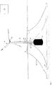
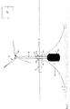
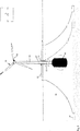
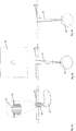
Gemäß der Erfindung trägt eine flächige Struktur oberhalb der Wasseroberfläche mindestens einen Turm mit z. B. einer Windkraftanlage. Unterhalb der Wasseroberfläche unter der flächigen Struktur ist ein Ballastgewicht vorgesehen, sodass der Schwerpunkt der gesamten Vorrichtung unterhalb des hydrostatischen Auftriebspunkt der flächigen Struktur liegt.According to the invention carries a flat structure above the water surface at least one tower with z. B. a wind turbine. Below the water surface under the planar structure, a ballast weight is provided, so that the center of gravity of the entire device is below the hydrostatic buoyancy point of the planar structure.
Durch das Ballastgewicht entsteht der Drang zur Senkrechtstellung des Turmes bzw. der gesamten Einheit. Sowohl die Tiefe, als auch die Masse des Ballastgewichts können an die Gegebenheiten, wie Windstärke, Seegang, Tide und/oder die gegebene Wassertiefe angepasst werden. Vorteilhaft ist ein tiefes Ballastgewicht, welches also einen großen Abstand zur flächigen Struktur aufweist. Durch die flächige Struktur werden die Bewegung der gesamten Vorrichtung im Wasser und ihre Krängung minimiert. Dabei wird die Stabilität gegenüber den Wellen und dem Winddruck auf den mindestens einen Turm erhöht. Die flächige Struktur sollte schwimmfähig sein und Lasten aufnehmen können. Vorteilhaft ist eine flächige Struktur mit einer großen Fläche parallel zur Wasseroberfläche. Die Länge der flächigen Struktur sollte mindestens einige ortsübliche Wellenlängen bzw. -höhen betragen, sodass die flächige Struktur ähnlich einem Brett auf den Wellen zum Liegen kommt, also nicht in ein Wellental fallen kann.The ballast weight creates the urge for the vertical position of the tower or the entire unit. Both the depth and the mass of the ballast weight can be adapted to the conditions such as wind strength, sea state, tides and / or the given depth of water. A low ballast weight is advantageous, which therefore has a large distance from the planar structure. The flat structure minimizes movement of the entire device in the water and their heeling. The stability against the waves and the wind pressure on the at least one tower is increased. The flat structure should be buoyant and able to take loads. Advantageous is a flat structure with a large area parallel to the water surface. The length of the planar structure should be at least some local wavelengths or heights, so that the flat structure similar to a board on the waves comes to rest, so can not fall into a wave trough.
Die Vorrichtung kann sich aufgrund einer geeigneten Form der flächige Struktur, des Turms oder des Rotors selbstständig immer in Wind- und/oder in Strömungsrichtung drehen. Geeignet bedeutet dabei, dass ein Teil der wind- oder wellenausgesetzten Oberfläche reduziert wird, also z. B. spitz zuläuft oder sich verjüngt, sodass sich dieser Teil immer in Windrichtung dreht und die restlich, größere Oberfläche dem Wind oder den Wellen möglichst ausweicht. Bei dem Rotor kann es sich um jede Art von Rotor handeln, z. B. horizontal oder vertikal angeordnete Rotoren.Due to a suitable shape of the planar structure, of the tower or of the rotor, the device can always rotate independently in the wind direction and / or in the direction of flow. Suitable means that a part of the wind or wave exposed surface is reduced, ie z. B. tapered or tapered so that this part always turns in the wind direction and the remaining, larger surface avoids the wind or the waves as possible. The rotor may be any type of rotor, e.g. B. horizontally or vertically arranged rotors.
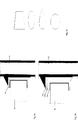
Die flächige Struktur kann aus einem oder mehreren beliebig geformten Teilen bestehen, die für eine einfache Montage und spätere Wartungen lösbar zusammen geflanscht oder gefügt sind. Die flächige Struktur kann aus einem oder mehreren Hohlkörpern oder flächigen Vollkörpern bestehen. Sie kann zur Wasseroberfläche hin ganz oder teileweise offen sein. D. h. der Querschnitt der Einzelkörper kann beliebiger Profile, wie z. B. ein Kastenprofil oder ein U-Profil aufweisen. Um die flächige Struktur eistauglich zu machen, können die seitlichen Außenumrandungen der flächigen Struktur keilförmig ausgestaltet sein. Friert das Wasser, so wird die flächige Struktur durch die Keilform der Außenumrandung aus dem Eis herausgehoben. Keilförmig bedeutet, dass der Außendurchmesser der flächigen Struktur oberhalb der Wasserlinie größer ist als unterhalb der Wasserlinie.The sheet-like structure may consist of one or more arbitrarily shaped parts, which are flanged or joined together for easy assembly and subsequent maintenance. The planar structure may consist of one or more hollow bodies or flat solid bodies. It can be completely or partially open to the water surface. Ie. the cross section of the single body can any profile, such as. B. have a box section or a U-profile. In order to make the flat structure eistauglich, the lateral outer edges of the sheet-like structure may be wedge-shaped. When the water freezes, the flat structure is lifted out of the ice by the wedge shape of the outer border. Wedge-shaped means that the outer diameter of the flat structure above the waterline is greater than below the waterline.
Der Turm kann ebenfalls aus einem oder mehreren Teilen bestehen, die für eine einfache Montage und spätere Wartungen lösbar zusammen geflanscht oder gefügt sind. Durch eine geeignete Form der flächigen Struktur, des Turmes und/oder des Rotors der Windkraftanlage kann erreicht werden, dass sich der Rotor selbstständig immer in die Windrichtung dreht. Der Turm kann unterschiedliche Formen aufweisen, z. B. zylinderförmig, aber auch tropfenförmig verkleidet, sodass der Turm sich (mit dem Rotor) selbstständig in den Wind stellt. Eine solche Spezialform des Turmes wird vor allem bei den drehbaren Turmvarianten angewendet, da dies neben der Minimierung der Windlasten dazu führt, dass sich der Turm selber in den Wind dreht. Der Turm kann starr mit der flächigen Struktur verbunden sein oder drehbar durch die flächige Struktur geführt werden. Je nach dem ist das Ballastgewicht durch mindestens ein separates Teil oder durch die Verlängerung des Turms mit der flächigen Struktur verbunden. Das separate Teil kann ebenfalls turmähnlich und starr sein, aber auch flexibel, wie z. B. eines oder mehrere Seile oder Ketten. Ist das Ballastgewicht durch die Verlängerung des Turms mit der flächigen Struktur verbunden, so dreht es sich gegebenenfalls mit der Verlängerung des Turms. Der Turm und die Verlängerung des Turms können durch zwei Lager ober- und unterhalb der flächigen Struktur mit ihr verbunden sein, oder nur einen oberen oder unteren Anschlag aufweisen, der, je nach Auftrieb des Turms und seiner Verlängerung, ein Durchrutschen des Turms und seiner Verlängerung nach unten oder oben verhindert.The tower may also consist of one or more parts which are releasably flanged or joined together for ease of assembly and subsequent servicing. By a suitable shape of the planar structure, the tower and / or the rotor of the wind turbine can be achieved that the rotor always turns independently in the wind direction. The tower can have different shapes, eg. B. cylindrical, but also dressed drop-shaped, so that the tower is (with the rotor) automatically in the wind. Such a special form of the tower is mainly used in the rotatable tower variants, as this, besides minimizing the wind loads, causes the tower itself to turn into the wind. The tower may be rigidly connected to the planar structure or rotatably guided by the planar structure. Depending on the ballast weight is connected by at least one separate part or by the extension of the tower with the flat structure. The separate part can also be tower-like and rigid, but also flexible, such. B. one or more ropes or chains. If the ballast weight is connected by the extension of the tower with the flat structure, it may rotate with the Extension of the tower. The tower and the extension of the tower may be connected by two bearings above and below the sheet structure with her, or have only an upper or lower stop which, depending on the buoyancy of the tower and its extension, slipping of the tower and its extension prevented downwards or upwards.
Das Ballastgewicht, auch Trimmkörper genannt, kann aus unterschiedlichen Materialien bestehen und es kann vormontiert oder ein Hohlkörper sein, der nachträglich mit Material gefüllt wird, wie z. B. feste Stoffe, Flüssigkeiten oder fließfähige Stoffe, die sich später verfestigen, wie z. B. Beton. Das nachträgliche Befüllen im tiefen Wasser lässt einen einfachen Transport der „leer” fast waagrecht treibenden Komponenten vom Ufer aus durch seichtes Wasser mit nachträglich anzubauenden flächigen Strukturen zu. Die Befüllung kann also im tiefen Wasser erfolgen, so dass die Senkrechtstellung der Komponenten erst nach dem Befüllen des Ballastkörpers eintritt. Auf diese Weise wird Transport, Aufbau und Montage der Vorrichtung erleichtert und die Kosten reduziert.The ballast weight, also called trim body may consist of different materials and it may be pre-assembled or a hollow body, which is subsequently filled with material, such as. As solids, liquids or flowable substances that solidify later, such. Concrete. The subsequent filling in the deep water allows easy transport of the "empty" almost horizontally floating components from the shore by shallow water with subsequently grown flat structures. The filling can thus be done in deep water, so that the vertical position of the components occurs only after the filling of the ballast body. In this way, the transport, construction and installation of the device is facilitated and reduces costs.
Das Volumen des Ballastgewichts, seine Form, sein Füllstand und/oder das Füllmaterial können sowohl einmal an die Betriebsbedingungen angepasst werden, als auch aktuell an die Betriebssituation (Tide, Unwetter) angepasst werden, indem z. B. ein fließfähiger Stoff zwischen dem Ballastgewicht und dem Turm oder der flächigen Struktur hin und hergepumpt wird. Das Ballastgewicht kann direkt an den Turm bzw. seine Verlängerung anstoßen, oder den Turm bzw. seine Verlängerung ganz oder teilweise umgeben.The volume of the ballast weight, its shape, its level and / or the filler can be both adapted to the operating conditions, as well as currently adapted to the operating situation (tide, storm) by z. B. a flowable material between the ballast weight and the tower or the planar structure is pumped back and forth. The ballast weight can directly abut the tower or its extension, or completely or partially surround the tower or its extension.
Die flächige Struktur kann im Seebett durch unterschiedliche flexible Verankerungsmöglichkeiten verankern werden. Die Verankerung dient dazu, dass die Vorrichtung an einem Ort gehalten wird. Durch das Ballastgewicht liegt der Schwerpunkt der gesamten Einheit so tief, dass darüber hinaus nur verhältnismäßig geringe Kräfte von den Verankerungsmitteln aufgenommen werden müssen. Auf diese Weise werden das Seebett und seine Lebewesen weder durch aufwändig einzurammende und tiefgehende Verankerungen beschädigt, noch ist es nötig, durch großflächige Betonierungen das Seebett zu versiegeln. Die Verankerungsmöglichkeiten ermöglichen darüber hinaus eine Anpassung an Gezeiten, Unwetter, Strömungen usw. Die Verankerungsmöglichkeiten bestehen aus Verbindungsmitteln und Ankersystemen. Die Verbindungsmittel zwischen der flächigen Struktur und den Ankersystemen kann aus unterschiedlichen Materialien in Seilform, Kettenform oder auch durch gelenkig gelagerte, starre Teile umgesetzt werden. Möglich sind z. B. Rohre oder andere Profile, die beweglich an der flächigen Struktur und an der oder den Ankersystemen befestigt sind. Die Ankersystem können ein oder mehrere (Halte-)Anker, z. B. Schwerlastanker oder speziell geformte Anker (wie im Schiffbau), oder eingebrachte Gegenstände im Seebett, wie z. B. Rohre, Spreizanker, Stäbe, Pfähle, Bohrpfähle und ähnliches sein.The flat structure can be anchored in the lake bed by different flexible anchoring options. The anchoring serves to keep the device in one place. Due to the ballast weight of the center of gravity of the entire unit is so deep that in addition only relatively small forces must be absorbed by the anchoring means. In this way, the lake bed and its creatures are neither damaged by elaborate einzurammende and deep anchorages, nor is it necessary to seal the lake bed by large concretions. The anchoring options also allow adaptation to tides, storms, currents, etc. The anchoring options consist of lanyards and anchor systems. The connecting means between the flat structure and the anchor systems can be implemented from different materials in rope form, chain shape or by articulated rigid parts. Possible are z. As pipes or other profiles which are movably mounted on the sheet structure and on or the anchor systems. The anchor system can one or more (holding) anchor, z. As heavy duty anchor or specially shaped anchor (as in shipbuilding), or introduced objects in the lake bed, such. As pipes, expansion anchors, rods, piles, bored piles and the like.
Die flächige Struktur könnte auch durch eine vorgespannte Verankerungsmöglichkeit als Halbtaucher ganz oder teilweise unter die Wasseroberfläche gezogen und fixiert werden, wobei das Ballastgewicht eine zusätzliche Stabilisierung der gesamten Einheit bewirkt. Bevorzugt ist eine flächige Struktur, die selber einen tiefen Schwerpunkt aufweist, also z. B. zu zwei Dritteln unter Wasser liegt. Auf diese Weise ist die flächige Struktur stabiler und das Schaukeln bzw. die Gefahr des Kippens/Kenterns der flächigen Struktur wird verringert.The planar structure could also be pulled and fixed completely or partially under the water surface by a prestressed anchoring option as semi-submersible, the ballast weight causing additional stabilization of the entire unit. Preferably, a planar structure, which itself has a low center of gravity, ie z. B. is two-thirds under water. In this way, the planar structure is more stable and the rocking or the danger of tipping / capsizing of the planar structure is reduced.
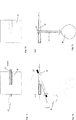
Die flächige Struktur kann eine oder mehrere Windmühlen tragen. Bei der Montage von mehreren Windmühlen mit einem oder mehreren zusammen gekuppelten Einzelschwimmern ist das Ballastgewicht im Zentrum der Lastannahme unabhängig von den Türmen oder mit einem im Zentrum stehenden Turm anzuordnen. Das Ballastgewicht kann aber auch aufgeteilt werden und sich unter jedem Turm befinden oder unter dem Schwerpunkt einer Gruppe von Türmen. Das Ballastgewicht kann ohne eine starre Verbindung im Zentrum der schwimmenden Struktur untergehängt werden. Hierzu kann das Ballastgewicht starr mit der Struktur verbunden werden oder durch Ketten, Seile oder Rohrverbindungen hängend mit der Struktur verbunden werden.The flat structure can carry one or more windmills. When installing several windmills with one or more single swimmers coupled together, the ballast weight in the center of the load assumption shall be located independently of the towers or with a tower in the center. The ballast weight can also be split and located under each tower or under the center of gravity of a group of towers. The ballast weight can be suspended in the center of the floating structure without a rigid connection. For this purpose, the ballast weight can be rigidly connected to the structure or connected by chains, ropes or pipe joints hanging with the structure.
Ausführungsbeispiele der Erfindung sind in den Zeichnungen gezeigt, wobeiEmbodiments of the invention are shown in the drawings, wherein
Ein unterschiedliches Drehen der schwimmenden Struktur
Bei den Ausführungsformen der
Zum Aufbau der Vorrichtung ist es möglich, dass der Unterwasserteil des Turms
Die
Die Haltestruktur
Es wird eine Turmhöhe zwischen 50 und 150 Metern erwartet. Die Fläche der flächigen Struktur
Claims (10)
Priority Applications (1)
| Application Number | Priority Date | Filing Date | Title |
|---|---|---|---|
| DE102010040887A DE102010040887A1 (en) | 2010-09-16 | 2010-09-16 | Floating device for supporting tower, particularly tower of wind turbine, in water, has planar structure for stabilizing device on water surface, where tower is supported through planner structure |
Applications Claiming Priority (1)
| Application Number | Priority Date | Filing Date | Title |
|---|---|---|---|
| DE102010040887A DE102010040887A1 (en) | 2010-09-16 | 2010-09-16 | Floating device for supporting tower, particularly tower of wind turbine, in water, has planar structure for stabilizing device on water surface, where tower is supported through planner structure |
Publications (1)
| Publication Number | Publication Date |
|---|---|
| DE102010040887A1 true DE102010040887A1 (en) | 2012-03-22 |
Family
ID=45768726
Family Applications (1)
| Application Number | Title | Priority Date | Filing Date |
|---|---|---|---|
| DE102010040887A Withdrawn DE102010040887A1 (en) | 2010-09-16 | 2010-09-16 | Floating device for supporting tower, particularly tower of wind turbine, in water, has planar structure for stabilizing device on water surface, where tower is supported through planner structure |
Country Status (1)
| Country | Link |
|---|---|
| DE (1) | DE102010040887A1 (en) |
Cited By (13)
| Publication number | Priority date | Publication date | Assignee | Title |
|---|---|---|---|---|
| FR2990476A1 (en) * | 2012-05-09 | 2013-11-15 | IFP Energies Nouvelles | Wind turbine for use at sea, has supporting unit for supporting mast of wind turbine in desired position, where supporting unit is interdependent of mast, and independent of movements of floating support |
| WO2014000802A1 (en) * | 2012-06-28 | 2014-01-03 | Alstom Renovables España, S.L. | Floating offshore wind turbine with damping structure |
| US20140103664A1 (en) * | 2012-05-11 | 2014-04-17 | Zachry Construction Corporation | Offshore wind turbine |
| WO2014060420A1 (en) * | 2012-10-15 | 2014-04-24 | Sereo Sas | V-shaped, bi-rotor wind generator on a spar floating structure |
| WO2014205603A1 (en) * | 2013-06-28 | 2014-12-31 | Tidal Harness Limited | Platform for tidal turbines |
| DE102013111115B3 (en) * | 2013-10-08 | 2015-01-22 | Linnhoff Offshore AG | Floating offshore wind turbine |
| CN104986301A (en) * | 2015-06-29 | 2015-10-21 | 武汉理工大学 | Combined type floating wind power generation platform |
| WO2015181428A1 (en) * | 2014-05-27 | 2015-12-03 | Esteyco S.A.P. | Floating substructure for a wind generator and method of installing same |
| WO2015181424A1 (en) * | 2014-05-27 | 2015-12-03 | Esteyco S.A.P. | Floating structure and method of installing same |
| DE102019103753A1 (en) * | 2019-02-14 | 2020-08-20 | Rwe Generation Se | Device and method for providing a floating foundation, as well as the use of a corresponding device |
| WO2020242427A1 (en) * | 2019-05-30 | 2020-12-03 | Михаил Юрьевич ЛАНДАУ | Method for installing a tower support for a wind turbine at sea |
| WO2024032921A1 (en) * | 2022-08-11 | 2024-02-15 | Dr. Ing. H.C. F. Porsche Aktiengesellschaft | Wind turbine installation and method for erecting a wind turbine installation |
| US12420894B2 (en) | 2021-05-06 | 2025-09-23 | Friede & Goldman United B.V. | Systems and methods for a rack structure for a transport vessel adapted for use with an offshore self-elevating vessel |
Citations (7)
| Publication number | Priority date | Publication date | Assignee | Title |
|---|---|---|---|---|
| US3256537A (en) * | 1963-01-09 | 1966-06-21 | Daniel W Clark | Mobile marine platform |
| FR2137117A2 (en) * | 1971-05-13 | 1972-12-29 | Emh | |
| FR2540065A1 (en) * | 1983-02-01 | 1984-08-03 | Creusot Loire | Floating and ballasted structure, held in its place in the open sea |
| DE19744174A1 (en) * | 1997-10-07 | 1999-04-08 | Otto Gerd Albrecht | Air flow converter for generating electrical energy without harmful substances on ocean |
| JP2005180351A (en) * | 2003-12-19 | 2005-07-07 | Yoshiro Shinoda | Water surface wind power generating device |
| JP2005264865A (en) * | 2004-03-19 | 2005-09-29 | Mitsubishi Heavy Ind Ltd | Windmill device |
| WO2009088489A1 (en) * | 2008-01-02 | 2009-07-16 | Nagan Srinivasan | Offshore floating production, storage, and off-loading vessel for use in ice-covered and clear water applications |
-
2010
- 2010-09-16 DE DE102010040887A patent/DE102010040887A1/en not_active Withdrawn
Patent Citations (7)
| Publication number | Priority date | Publication date | Assignee | Title |
|---|---|---|---|---|
| US3256537A (en) * | 1963-01-09 | 1966-06-21 | Daniel W Clark | Mobile marine platform |
| FR2137117A2 (en) * | 1971-05-13 | 1972-12-29 | Emh | |
| FR2540065A1 (en) * | 1983-02-01 | 1984-08-03 | Creusot Loire | Floating and ballasted structure, held in its place in the open sea |
| DE19744174A1 (en) * | 1997-10-07 | 1999-04-08 | Otto Gerd Albrecht | Air flow converter for generating electrical energy without harmful substances on ocean |
| JP2005180351A (en) * | 2003-12-19 | 2005-07-07 | Yoshiro Shinoda | Water surface wind power generating device |
| JP2005264865A (en) * | 2004-03-19 | 2005-09-29 | Mitsubishi Heavy Ind Ltd | Windmill device |
| WO2009088489A1 (en) * | 2008-01-02 | 2009-07-16 | Nagan Srinivasan | Offshore floating production, storage, and off-loading vessel for use in ice-covered and clear water applications |
Cited By (20)
| Publication number | Priority date | Publication date | Assignee | Title |
|---|---|---|---|---|
| FR2990476A1 (en) * | 2012-05-09 | 2013-11-15 | IFP Energies Nouvelles | Wind turbine for use at sea, has supporting unit for supporting mast of wind turbine in desired position, where supporting unit is interdependent of mast, and independent of movements of floating support |
| US20140103664A1 (en) * | 2012-05-11 | 2014-04-17 | Zachry Construction Corporation | Offshore wind turbine |
| US9476409B2 (en) * | 2012-05-11 | 2016-10-25 | Zachry Construction Corporation | Offshore wind turbine |
| WO2014000802A1 (en) * | 2012-06-28 | 2014-01-03 | Alstom Renovables España, S.L. | Floating offshore wind turbine with damping structure |
| US9522716B2 (en) | 2012-06-28 | 2016-12-20 | Alstom Renewable Technologies | Floating offshore wind turbine with damping structure |
| WO2014060420A1 (en) * | 2012-10-15 | 2014-04-24 | Sereo Sas | V-shaped, bi-rotor wind generator on a spar floating structure |
| CN105339651A (en) * | 2013-06-28 | 2016-02-17 | 潮汐治理有限公司 | Platform for tidal turbines |
| WO2014205603A1 (en) * | 2013-06-28 | 2014-12-31 | Tidal Harness Limited | Platform for tidal turbines |
| GB2531460A (en) * | 2013-06-28 | 2016-04-20 | Tidal Harness Ltd | Platform for tidal turbines |
| DE102013111115B3 (en) * | 2013-10-08 | 2015-01-22 | Linnhoff Offshore AG | Floating offshore wind turbine |
| US10677224B2 (en) | 2013-10-08 | 2020-06-09 | Cruse Offshore Gmbh | Floating wind power plant |
| WO2015181424A1 (en) * | 2014-05-27 | 2015-12-03 | Esteyco S.A.P. | Floating structure and method of installing same |
| WO2015181428A1 (en) * | 2014-05-27 | 2015-12-03 | Esteyco S.A.P. | Floating substructure for a wind generator and method of installing same |
| CN106573665A (en) * | 2014-05-27 | 2017-04-19 | 埃斯特科股份公司 | Floating structure and installation method thereof |
| CN106687368A (en) * | 2014-05-27 | 2017-05-17 | 埃斯特科股份公司 | Floating infrastructure for wind turbines and method of installation thereof |
| CN104986301A (en) * | 2015-06-29 | 2015-10-21 | 武汉理工大学 | Combined type floating wind power generation platform |
| DE102019103753A1 (en) * | 2019-02-14 | 2020-08-20 | Rwe Generation Se | Device and method for providing a floating foundation, as well as the use of a corresponding device |
| WO2020242427A1 (en) * | 2019-05-30 | 2020-12-03 | Михаил Юрьевич ЛАНДАУ | Method for installing a tower support for a wind turbine at sea |
| US12420894B2 (en) | 2021-05-06 | 2025-09-23 | Friede & Goldman United B.V. | Systems and methods for a rack structure for a transport vessel adapted for use with an offshore self-elevating vessel |
| WO2024032921A1 (en) * | 2022-08-11 | 2024-02-15 | Dr. Ing. H.C. F. Porsche Aktiengesellschaft | Wind turbine installation and method for erecting a wind turbine installation |
Similar Documents
| Publication | Publication Date | Title |
|---|---|---|
| DE102010040887A1 (en) | Floating device for supporting tower, particularly tower of wind turbine, in water, has planar structure for stabilizing device on water surface, where tower is supported through planner structure | |
| EP3019740B1 (en) | Floating wind turbine with a floating foundation, and method for installation of such a wind turbine | |
| EP2360373B1 (en) | Offshore station, foundation for an offshore station, and method for building an offshore station | |
| DE102011052024B4 (en) | Shimmering structure | |
| DE102006033215B4 (en) | Device for stable storage of installations or structures at sea | |
| EP1288122B1 (en) | Floating support for a construction extending above the water surface | |
| EP1876093B1 (en) | Wind turbine with a floating offshore foundation | |
| DE10349109B4 (en) | Foundation for an offshore wind energy plant | |
| EP2311725A2 (en) | Floating support with improved bracing | |
| EP2539219B1 (en) | Device for transporting and installing an arrangement of an offshore wind turbine comprising a raft foundation and method for transporting and installing such an arrangement having a raft foundation | |
| DE10101405A1 (en) | Offshore wind power unit for supplying energy has a rotor on a tower with a pillar underneath the tower fitted in a steel frame with three legs, leg braces linking the legs and tie-bars between the pillar base and each leg. | |
| EP2591176B1 (en) | Offshore facility, in particular wind turbine | |
| WO2018054532A1 (en) | Structure for erecting on the surfaces of bodies of water, and method for erecting same | |
| DE69520214T2 (en) | OFFSHORE WIND / WAVE ENERGY TRANSFORMER | |
| DE20100588U1 (en) | Off-shore wind turbine | |
| EP3428345A1 (en) | Foundation for an offshore wind motor | |
| EP1234978A2 (en) | Off-shore wind turbine | |
| DE102007002314A1 (en) | Device for lifting, transporting and lowering offshore-wind towers and their underpins or underpins of offshore-platform, has floating body and biological contactor, where biological contactor is temporarily connected with floating body | |
| WO2011131160A2 (en) | Stand structure | |
| DE102008031042B4 (en) | Modular floating unit for wind and turbines at sea | |
| EP3922845B1 (en) | Floating offshore structure and method of installation | |
| DE102011109251A1 (en) | Catamaran pontoon used for foundation construction of offshore wind turbine, has ventilating portion to provide ventilation to interior and pressure generating portion to generate negative pressure in suction element | |
| DE102011120378A1 (en) | Off-shore wind-power plant for being installed at bottom of sea, has nacelle located with rotor and anchoring unit on swimming foundation, which is formed as annular body that is integrally assembled or formed from prefabricated segments | |
| DE102006056772A1 (en) | Position stabilizing method for floating object i.e. ship, involves dumping weights from floating body to seabed, and obtaining traction force in connections between weights and floating body, which is pulled downwards by traction force | |
| EP4493814A1 (en) | Flow power plant |
Legal Events
| Date | Code | Title | Description |
|---|---|---|---|
| R119 | Application deemed withdrawn, or ip right lapsed, due to non-payment of renewal fee |
Effective date: 20130403 |