EP2906136B1 - Hautbehandlungsvorrichtung - Google Patents
Hautbehandlungsvorrichtung Download PDFInfo
- Publication number
- EP2906136B1 EP2906136B1 EP13811004.4A EP13811004A EP2906136B1 EP 2906136 B1 EP2906136 B1 EP 2906136B1 EP 13811004 A EP13811004 A EP 13811004A EP 2906136 B1 EP2906136 B1 EP 2906136B1
- Authority
- EP
- European Patent Office
- Prior art keywords
- skin
- wheel
- angular position
- treatment device
- facets
- Prior art date
- Legal status (The legal status is an assumption and is not a legal conclusion. Google has not performed a legal analysis and makes no representation as to the accuracy of the status listed.)
- Not-in-force
Links
- 238000011282 treatment Methods 0.000 title claims description 48
- 238000011269 treatment regimen Methods 0.000 claims description 24
- 230000037303 wrinkles Effects 0.000 claims description 7
- 239000000049 pigment Substances 0.000 claims description 3
- 231100000444 skin lesion Toxicity 0.000 claims description 3
- 206010040882 skin lesion Diseases 0.000 claims description 3
- 230000001594 aberrant effect Effects 0.000 description 6
- 238000010304 firing Methods 0.000 description 5
- 238000001514 detection method Methods 0.000 description 4
- 230000001419 dependent effect Effects 0.000 description 3
- 230000000694 effects Effects 0.000 description 2
- 230000008263 repair mechanism Effects 0.000 description 2
- 230000037075 skin appearance Effects 0.000 description 2
- 230000021615 conjugation Effects 0.000 description 1
- 238000012937 correction Methods 0.000 description 1
- 230000003247 decreasing effect Effects 0.000 description 1
- 238000006073 displacement reaction Methods 0.000 description 1
- 238000012544 monitoring process Methods 0.000 description 1
- 230000003287 optical effect Effects 0.000 description 1
- 230000036555 skin type Effects 0.000 description 1
Images


Classifications
-
- A—HUMAN NECESSITIES
- A61—MEDICAL OR VETERINARY SCIENCE; HYGIENE
- A61B—DIAGNOSIS; SURGERY; IDENTIFICATION
- A61B18/00—Surgical instruments, devices or methods for transferring non-mechanical forms of energy to or from the body
- A61B18/18—Surgical instruments, devices or methods for transferring non-mechanical forms of energy to or from the body by applying electromagnetic radiation, e.g. microwaves
- A61B18/20—Surgical instruments, devices or methods for transferring non-mechanical forms of energy to or from the body by applying electromagnetic radiation, e.g. microwaves using laser
- A61B18/203—Surgical instruments, devices or methods for transferring non-mechanical forms of energy to or from the body by applying electromagnetic radiation, e.g. microwaves using laser applying laser energy to the outside of the body
-
- G—PHYSICS
- G02—OPTICS
- G02B—OPTICAL ELEMENTS, SYSTEMS OR APPARATUS
- G02B26/00—Optical devices or arrangements for the control of light using movable or deformable optical elements
- G02B26/08—Optical devices or arrangements for the control of light using movable or deformable optical elements for controlling the direction of light
- G02B26/10—Scanning systems
- G02B26/12—Scanning systems using multifaceted mirrors
-
- A—HUMAN NECESSITIES
- A61—MEDICAL OR VETERINARY SCIENCE; HYGIENE
- A61B—DIAGNOSIS; SURGERY; IDENTIFICATION
- A61B18/00—Surgical instruments, devices or methods for transferring non-mechanical forms of energy to or from the body
- A61B2018/00315—Surgical instruments, devices or methods for transferring non-mechanical forms of energy to or from the body for treatment of particular body parts
- A61B2018/00452—Skin
- A61B2018/0047—Upper parts of the skin, e.g. skin peeling or treatment of wrinkles
-
- A—HUMAN NECESSITIES
- A61—MEDICAL OR VETERINARY SCIENCE; HYGIENE
- A61B—DIAGNOSIS; SURGERY; IDENTIFICATION
- A61B18/00—Surgical instruments, devices or methods for transferring non-mechanical forms of energy to or from the body
- A61B2018/00636—Sensing and controlling the application of energy
- A61B2018/00773—Sensed parameters
- A61B2018/00779—Power or energy
-
- A—HUMAN NECESSITIES
- A61—MEDICAL OR VETERINARY SCIENCE; HYGIENE
- A61B—DIAGNOSIS; SURGERY; IDENTIFICATION
- A61B18/00—Surgical instruments, devices or methods for transferring non-mechanical forms of energy to or from the body
- A61B18/18—Surgical instruments, devices or methods for transferring non-mechanical forms of energy to or from the body by applying electromagnetic radiation, e.g. microwaves
- A61B18/20—Surgical instruments, devices or methods for transferring non-mechanical forms of energy to or from the body by applying electromagnetic radiation, e.g. microwaves using laser
- A61B2018/2035—Beam shaping or redirecting; Optical components therefor
- A61B2018/20351—Scanning mechanisms
- A61B2018/20355—Special scanning path or conditions, e.g. spiral, raster or providing spot overlap
-
- A—HUMAN NECESSITIES
- A61—MEDICAL OR VETERINARY SCIENCE; HYGIENE
- A61B—DIAGNOSIS; SURGERY; IDENTIFICATION
- A61B18/00—Surgical instruments, devices or methods for transferring non-mechanical forms of energy to or from the body
- A61B18/18—Surgical instruments, devices or methods for transferring non-mechanical forms of energy to or from the body by applying electromagnetic radiation, e.g. microwaves
- A61B18/20—Surgical instruments, devices or methods for transferring non-mechanical forms of energy to or from the body by applying electromagnetic radiation, e.g. microwaves using laser
- A61B2018/2035—Beam shaping or redirecting; Optical components therefor
- A61B2018/205547—Controller with specific architecture or programmatic algorithm for directing scan path, spot size or shape, or spot intensity, fluence or irradiance
Definitions
- This invention relates to a skin treatment device comprising a light source for providing a light beam for optically treating a skin, a wheel with a wheel surface for reflecting the light beam towards the skin, driving means for rotating the wheel for changing an angular position of the wheel, wherein different angular positions of the wheel correspond to respective different directions of reflection for the light beam resulting in the light beam being reflected, during use, towards a corresponding plurality of different locations on the skin, said plurality of different locations forming a skin-treatment pattern, an angular position detector for detecting the angular position of the wheel, and a control circuit for controlling the light source.
- Such a skin treatment device is, e.g., disclosed in the United States patent application published as US 2012/0197357 A1 .
- Said skin treatment device comprises a laser source and an optical pattern generator for creating microscopic treatment zones (MTZs) of thermally denatured skin tissue surrounded by unaffected skin tissue.
- MTZs microscopic treatment zones
- An axicon wheel with a plurality of axicon segments deflects the laser beam towards a corresponding plurality of different locations on the skin surface which form a skin-treatment pattern.
- a control circuit controls the laser source to randomly illuminate individual axicon segments. While the user drags the device along the skin surface, a random pattern of MTZs is applied to the skin surface.
- An intensity level set by the user determines the density of the random pattern.
- every axicon facet has a triggering flake that is detected by a flake detector upon passing the flake detector during rotation of the axicon wheel.
- the flake detector is coupled to the control circuit, which determines the rotational speed of the axicon wheel, based on the flake detector signal. Based on the rotational speed of the axicon wheel and a measured speed at which the user drags the device along the skin surface, the control circuit is able to provide the randomly distributed MTZs at a more or less constant density.
- a similar skin treatment device is disclosed in WO 2013/036761 and comprises, in one embodiment, a motor/pulse control system to control the operation of the pulsed light source and of the motor of a beam scanning system, wherein the motor/pulse control system may control the pulsed light source by monitoring the rotation and/or position of an encoder arranged to indicate the rotation and/or position of a rotating beam-scanning element of the beam scanning system.
- the encoder is in the form of a wheel or disk fixed to the rotating beam-scanning element and including a number of detectable features around its circumference. The number of detectable features may be equal to or a multiple of the number of sectors of the scanning element.
- the rotation and/or rotational position of the scanning element may be determined by detecting the detectable features of the encoder.
- the encoder includes one detectable feature corresponding to each sector of the scanning element, the detection of each detectable feature passing by a particular point triggers a pulse from the light source.
- US 2012/025331 A1 Another similar skin treatment device is disclosed in US 2012/025331 A1 . It comprises a scanning system including a disc-shaped rotating element having deflection sectors. The deflection sectors are arranged around a circumference of the rotating element and are configured to deflect the light beam by different angles. Although the possibility to set an intensity level does provide some control over the operation of the device, there is still a need for improving treatment control to better adapt to differences in skin type, skin condition, skin treatment and user preferences. It may, e.g., be desirable to make the operation of the device more specific for certain skin features, such as wrinkles, fine lines or pigmented spots.
- a skin treatment device comprising a light source for providing a light beam for optically treating a skin, a wheel with a wheel surface for reflecting the light beam towards the skin, driving means for rotating the wheel for changing an angular position of the wheel, different angular positions of the wheel corresponding to respective different directions of reflection for the light beam resulting in the light beam being reflected, during use, towards a corresponding plurality of different locations on the skin, said plurality of different locations forming a skin-treatment pattern, an angular position detector for detecting the angular position of the wheel or a parameter corresponding with said angular position, a storage means storing a predefined skin-treatment pattern and a relation between the different angular positions of the wheel, or the parameter corresponding with said angular position, and the corresponding respective different directions of reflection for the light beam, or a parameter corresponding with said direction of reflection, and a control circuit coupled to the light source, the angular position detector and the storage means
- the device With the device according to the invention it is possible to start treatment at a selected angular position of the wheel and a corresponding direction of reflection of the light beam or, generally, it is possible to provide MTZs according to a predefined pattern on the skin by successively reflecting the light beam in a selected sequence of directions of reflection corresponding with the predefined skin-treatment pattern. Because the reflection directions corresponding to the different angular positions of the wheel are fixed, knowledge of the angular position of the wheel, obtained by means of the angular position detector, makes it possible to instantaneously know the direction in which light from the light source is reflected. For example, the control circuit may control the light source to illuminate the wheel surface only during each first or second half of each revolution of the wheel.
- Combining the knowledge of the angular position with the stored corresponding directions of reflection makes it possible for the control circuit to create MTZs only at selected positions on the skin according to a predefined skin-treatment pattern, which may e.g. be selected by the user. While dragging the device along the skin, a skin-treatment pattern with MTZs at pre-selected locations on the skin appears instead of the random pattern generated by the known device.
- the skin-treatment pattern may comprise, e.g., straight vertical, horizontal or diagonal lines of MTZs. Also wobbling patterns of MTZs, or separated spots of MTZs of different shapes may be generated.
- the angular position detector is arranged to detect a passage of an identification element associated with a predetermined one of the different angular positions of the wheel.
- the identification element may be a property of the wheel surface itself, an element attached to the wheel surface at a certain position or just an element provided on or at the wheel at some predetermined angular position.
- a passage of a second or even more unique identification elements may be detectable, each unique identification element corresponding to a different angular position.
- the invention may be used with any kind of angular position detector for detecting the angular position of the wheel, or with any kind of detector to detect a parameter corresponding with said angular position.
- the wheel surface comprises multiple facets for reflecting the light beam towards the skin in mutually different directions of reflection, each facet corresponding to one of the different directions of reflection.
- the identification element is associated with a predetermined single one of the multiple facets.
- An example of a suitable wheel is an axicon wheel. It is however to be noted that the invention is not at all limited to the use of faceted wheels or axicon wheels. For example, a wheel whose direction of reflection gradually changes in its circumferential direction could be used in a similar way and with similar advantageous effects. In fact, by further increasing the number of facets and decreasing the differences in orientation between subsequent facets, an approximation of such a wheel with a circumferentially gradually and continuously changing direction of reflection is obtained.
- the storage means is operative to store a relation between the different angular positions of the wheel and the corresponding respective different directions of reflection for the light beam, or a parameter corresponding with said directions of reflection.
- any parameter corresponding with said angular position may be used by the storage means.
- any parameter corresponding with said direction of reflection may be used by the storage means.
- the storage means is operative to store a sequence of the multiple facets, and the control circuit is arranged to selectively illuminate the facets based on the stored sequence of the multiple facets and the passage of the predetermined single one of the multiple facets.
- the parameter corresponding with the direction of reflection is a sequence number of the facets, and the angular position is monitored based on the passage of the predetermined single one of the multiple facets and the rotational speed of the wheel.
- the device further comprises a skin feature detector for detecting characterizing features of the skin, the feature detector being coupled to the control circuit and the control circuit being arranged to define the predefined skin-treatment pattern, based on the detected characterizing features.
- the detected skin features may, e.g., be wrinkles, pigment spots or skin lesions.
- the applied treatment pattern may then, e.g., follow the wrinkle or treat the pigment spot without also treating the surrounding skin areas.
- Exemplary detectors for detecting skin features and skin properties are described in, e.g., United States patent application US 2006/0239547 A1 .
- the detection of the passage of the predetermined single one of the multiple facets may be performed in many different ways.
- the reliability of the detection of said passage may be improved by combining two different ways of recognizing a specific facet.
- the predetermined single one of the multiple facets may have a translucency coefficient different from that of the other facets
- the angular position detector may comprise a light sensor for detecting a portion of the light beam having passed through the predetermined single one of the multiple facets.
- each facet may comprise a flake, the flake of the predetermined single one of the multiple facets being geometrically different from the flakes of the other facets, the angular position detector being arranged to detect the geometrically different flake.
- the regular trigger signal for triggering the light source can also be used for detecting the passage of the predetermined single one of the multiple facets. All facets, except the predetermined single one of the multiple facets, may provide the same trigger signal as known from the prior art.
- the angular position detector provides a distinct signal that is recognized by the control circuit.
- Geometrically different may, e.g., mean that the geometrically different flake is shorter than the other flakes or that the geometrically different flake comprises two flake parts separated by a gap.
- the wheel surface may comprise a hole which is associated with the predetermined single one of the multiple facets, and wherein the angular position detector comprises a second light source and a light sensor arranged such that light from the second light source can reach the light sensor through the hole.
- a further reflective surface may be provided at the wheel surface, wherein the further reflective surface is associated with the predetermined single one of the multiple facets, and wherein the angular position detector comprises a second light source and a light sensor, arranged such that light from the second light source can reach the light sensor via the further reflective surface.
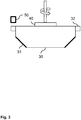
- FIG. 1 schematically shows a skin treatment device 10.
- the device 10 comprises a light source 20, in this event a laser source 20, for providing a light beam 21.
- An axicon wheel 30 with a plurality of axicon facets 31 deflects the light beam 21 through an objective lens 75 and an exit window 70 of the device 10 towards a skin 80.
- Each axicon facet 31 provides a respective different direction of reflection for the light beam 21. Accordingly, during rotation of the axicon wheel 30, the light beam 21 is reflected towards a corresponding plurality of different locations at the skin 80.
- the light beams create microscopic treatment zones (MTZs) of thermally denatured skin tissue surrounded by unaffected tissue. This treatment boosts skin repair mechanisms and improves skin appearance.
- MTZs microscopic treatment zones
- the laser source 20 is coupled to a control circuit 60 which controls the laser source to illuminate individual axicon facets 31 at selected moments.
- the axicon wheel 30 is rotated by driving means 40, such that the different facets 31 of the wheel 30 successively pass the path of the incoming light beam 21.
- the reflective surface areas of the different facets 31 of the wheel 30 are oriented at different angles in order to reflect the light 21 into different directions, causing the light to impinge on the skin 80 at different positions within a range of reachable positions.
- the axicon wheel 30 further comprises triggering flakes 32 which are provided next to the facets 31. Passage of the triggering flakes 32 is detected by a flake detector 50.
- the flake detector 50 is coupled to the control circuit 60.
- the frequency of the trigger signal generated by the flake detector 50 is dependent on the rotational speed of the axicon wheel 30.
- the control circuit 60 controls the light source 20 to emit light during a desired portion of each rotation of the wheel 30.
- the control circuit 60 may, e.g., provide a light pulse at 2, 4, 6 or even 12 of the facets 30 passing during one rotation.
- the device 10 may comprise means 90 for determining the hand speed with which the user drags the device 10 along the skin surface 80.
- the control circuit 60 is able to adapt a firing rate of the light source 20 depending on the measured hand speed in order to provide the MTZs at a more or less constant density which is independent of the hand speed.
- the control circuit 60 of the device 10 is not only capable of adapting the firing rate of the light source 20 to a rotational speed of the axicon wheel 30 and the measured hand speed of the user, but the control circuit 60 is also arranged to select the actual facets 31 that are to be illuminated by the light source 20 to provide a predefined skin-treatment pattern of MTZs at the skin 80.
- the desired skin-treatment pattern may for example be selected by the user.
- the device 10 may further comprise a skin feature detector 95 for detecting, e.g., wrinkles, skin lesions, pigmented spots or other skin features.
- the skin feature detector 95 may also be operative to detect skin properties such as color or skin moisture.
- the skin feature detector may, e.g., comprise a camera for observing the skin 80 or a detector for detecting and analyzing the treatment light beam 21 after reflecting at the skin surface 80.
- the skin feature detector is coupled to the control circuit 60, such that the treatment can be adapted to the detected features.
- the light source 20 may be controlled such that the treatment only affects a detected wrinkle or pigmented spot.
- the light source 20 may also be controlled such that selected parts of the skin are not treated.
- FIG 2 schematically shows a top view of a prior art axicon wheel 30 for the skin treatment device 10 of figure 1 .
- the axicon wheel 30 comprises twelve facets 31 for redirecting and reflecting light coming from the light source 20. Each facet 31 is accompanied by a trigger flake 32. Passage of the trigger flakes 32 is detected by the flake detector 50. The light source 20 is controlled in dependence on the trigger signal generated by the flake detector 50.
- Figure 3 shows a cross section of the axicon wheel 30 of figure 1 .
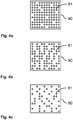
- Figures 4a, 4b and 4c show examples of treatment patterns that may be obtained with the skin treatment device of figure 1 when the prior art axicon wheel 30 according to figure 2 is used.
- These exemplary patterns of MTZs 81 on the skin 80 are obtained by randomly illuminating facets 31 on the axicon wheel 30 at a controlled firing rate while dragging the device 10 over the skin surface 80.
- the firing rate is controlled in dependence on the observed rotational speed of the axicon wheel and the measured hand speed of the user.
- the firing rate is controlled such that a more or less constant density of MTZs is provided independent of the hand speed.
- the density may be selected, e.g., dependent on a user-selected intensity level and/or on one or more automatically detected skin properties.
- figure 4a shows an example of a high-density pattern
- figure 4b shows an example of a medium-density pattern
- figure 4c shows an example of a low-density pattern.
- a 'normal' trigger flake 32 is shown together with the resulting trigger signal 132 generated by the flake detector 50.
- all flakes 32 of the prior art axicon wheel 30 have the same shape (at least in the dimensions observed by the flake detector 50).
- the frequency of the trigger signal 32 depends on the rotational speed of the wheel 30.
- the width of the trigger pulses depends on the width of the trigger flakes 32.
- Figures 5b and 5c show exemplary trigger signals for devices 10 according to the invention having an axicon wheel 30 with mutually different trigger flakes 33, 34.
- the trigger flakes 33 is made different from the others.
- the flake 33 is made different by splitting one normal flake 32 into two parts with a gap in between. Every time this aberrant flake 33 passes the flake detector 50, the trigger signal 133 is different from the trigger signal 132 when the normal flakes 32 pass. Instead of one trigger pulse, the aberrant flake 33 causes two distinct smaller pulses.
- the control circuit knows that the facet 31 associated with this aberrant flake 33 passes the detector and thus also knows the exact rotational position of the axicon wheel 30. This makes it possible for the control circuit 60 to enable only selected facets 31 of the axicon wheel 30 to be illuminated.
- Figure 5c shows an alternative way of providing an aberrant flake 34.
- This flake 34 is half as wide as a normal flake 32, resulting in a smaller trigger pulse in the trigger signal 134. Detection of this smaller pulse indicates passage of the predetermined facet 34 associated with the aberrant flake 34.
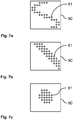
- Figures 6a, 6b, 6c , 7a, 7b and 7c show examples of skin-treatment patterns obtained by a skin treatment device according to the invention.
- the patterns of MTZs 81 at the skin 80 are provided by selectively illuminating some or all of the facets 31 at the wheel 30, one scan line at a time. It is to be noted that the patterns shown in these figures (and in figures 4a, 4b, 4c ) show a horizontal scan line and a device 10 that moves over the skin surface 80 in a direction perpendicular to the scan line. When the device is dragged along the skin surface in a different, possibly not straight, direction, then the pattern will be skewed accordingly.
- the selection of facets 31 to be illuminated may depend on the direction of movement of the device.
- FIG 6a a pattern is shown that is obtained by illuminating, at every scan line, all facets 31 of the axicon wheel 30. For obtaining this pattern, it is not necessary for the device 10 to be able to know the exact angular position of the wheel 30.
- the patterns of figures 6b and 6c (and 7a, 7b, 7c) it is important to determine the angular position of the wheel, for example by detecting when a predetermined single one of the multiple facets passes a selected position in the device 10. When detecting the passage of the predetermined single one of the multiple facets, the exact sequence of different facet orientations can be determined, which allows drawing the desired MTZ patterns on the skin 80.
- the device may however use any suitable angular position detector for detecting the actual angular position of the wheel 30.
- Figure 6b shows a pattern obtained by reflecting the light beam at only two of the facets 31. These two facets may or may not be provided adjacent to each other on the axicon wheel 30. The orientation of these two facets 31 is only slightly different, resulting in the corresponding MTZs 81 being located adjacent to each other. The small vertical treatment pattern may follow a wrinkle or other skin feature that is detected by a skin feature detector of the device 10.
- Figure 6c shows a pattern requiring four facets 31 to be illuminated for every scan line. For both the patterns of figure 6b and 6c , the same facets 31 are illuminated at every scan line (assuming that no corrections are made for any displacements of the device 10 in directions parallel to the orientation of the scan line).
- a storage means 91 is coupled to the control circuit and stores the predefined skin-treatment pattern and a relation between the different angular positions of the wheel 30 and the corresponding respective different directions of reflection for the light beam 21.
- the storage means 91 may store a database comprising a list of facet numbers, their positions at the wheel 30 and the corresponding directions of reflection.
- the database may store information about which facet is associated with which identification element.
- the control circuit 60 is operative to control the light source 20 in dependence on the angular position detected by the angular position detector, in this example the passage of the identification element, in such a way that, for each revolution of the wheel 30, the light beam 21 only illuminates the wheel surface at selected angular positions or facets to realize the predefined skin-treatment pattern.
- the patterns of figures 7a, 7b and 7c may follow specific detected skin features or may just be selected and applied at the position where the device happens to be placed at the skin surface 80.
- Figure 8 shows some examples of angular position detectors in a skin treatment device according to the invention.
- the normal flake detector 50 that has already been described above may be used for detecting a flake 34 with a different shape.
- the flake detector 50 may, e.g., be able to detect the shorter flake 34 that has also been discussed above with reference to figure 5c .
- an additional flake detector 51 may be provided adjacent to the first flake detector 50 for detecting a longer flake 53 that only passes once for every revolution of the wheel 30.
- a similar effect is obtained by providing one shorter flake, such that the additional flake detector 51 detects all flakes except the shorter one.
- the predetermined facet 31 then is the facet 31 for which only the first flake detector 50 provides a trigger pulse.
- Another way of detecting specific facets 31 is to place a photo detector 52 behind the facets 31 of the axicon wheel 30 and make the predetermined single one of the facets slightly more or slightly less translucent than the other ones. When the different facet passes the photo detector 52, the photo detector signal provides a different signal which thus indicates the passage of the predetermined single one of the facets. If the light source 20 is controlled such that all facets are illuminated, then the treatment light beam 21 may also be used for detecting the different facets. Otherwise, it may be preferred to use a separate additional light source for this purpose.
- the wheel surface may comprise a special marking 54 that is detected by a detector (not shown) capable of recognizing the marking.
- the marking 54 is a colored dot detected by a camera or a reflective spot detected by a combination of a light emitter and a photo detector.
- the marking 54 may also be a hole in the wheel 30, with a light emitter and a photo detector being provided on opposite sides of the wheel 30.
- Figure 9 shows a further example of an angular position detector in a skin treatment device according to the invention.
- This embodiment makes use of the differences in orientation between the different facets 31.
- an additional light source 22 is provided and a photo detector 56 for detecting light from the additional light source 22 after reflection at the predetermined facet 31.
- Different facets 31 reflect the light in different directions.
- a small slit 55 in front of the photo detector 56 ensures that only light reflected at precisely the correct angle by the predetermined single one of the multiple facets reaches the photo detector 56.
- Light that is reflected by facets other than the predetermined single one of the facets will not reach the photo detector 56.
- the photo detector 56 thus provides a trigger signal every time the predetermined single one of the multiple facets 31 passes.
Landscapes
- Physics & Mathematics (AREA)
- Health & Medical Sciences (AREA)
- Optics & Photonics (AREA)
- Surgery (AREA)
- Life Sciences & Earth Sciences (AREA)
- Heart & Thoracic Surgery (AREA)
- Molecular Biology (AREA)
- Nuclear Medicine, Radiotherapy & Molecular Imaging (AREA)
- Engineering & Computer Science (AREA)
- Biomedical Technology (AREA)
- Electromagnetism (AREA)
- Medical Informatics (AREA)
- Otolaryngology (AREA)
- Animal Behavior & Ethology (AREA)
- General Health & Medical Sciences (AREA)
- Public Health (AREA)
- Veterinary Medicine (AREA)
- General Physics & Mathematics (AREA)
- Radiation-Therapy Devices (AREA)
- Measuring And Recording Apparatus For Diagnosis (AREA)
- Laser Surgery Devices (AREA)
Claims (14)
- Hautbehandlungsvorrichtung (10), umfassend:- eine Lichtquelle (20) zum Bereitstellen eines Lichtstrahls (21) für die optische Behandlung einer Haut (80),- ein Rad (30) mit einer Radoberfläche (31) zum Reflektieren des Lichtstrahls (21) zu der Haut (80),- Antriebsmittel (40) zum Drehen des Rades (30), um eine Winkelposition des Rades (30) zu ändern, wobei unterschiedliche Winkelpositionen des Rades (30) jeweiligen unterschiedlichen Reflexionsrichtungen für den Lichtstrahl (21) entsprechen, was dazu führt, dass der Lichtstrahl (21), bei Gebrauch, zu einer entsprechenden Vielzahl von unterschiedlichen Stellen auf der Haut reflektiert wird, wobei die Vielzahl von unterschiedlichen Stellen ein Hautbehandlungsmuster bildet, und- einen Winkelpositionsdetektor (50, 51, 52, 56) zum Erkennen der Winkelposition des Rades (30) oder eines Parameters, der der Winkelposition entspricht, dadurch gekennzeichnet,dass die Hautbehandlungsvorrichtung weiter umfasst:- ein Speichermittel (91), das ein vorausdefiniertes Hautbehandlungsmuster und eine Beziehung zwischen den unterschiedlichen Winkelpositionen des Rades (30), oder dem Parameter, der der Winkelposition entspricht, und den entsprechenden jeweiligen unterschiedlichen Reflexionsrichtungen für den Lichtstrahl (21), oder einem Parameter, der der Reflexionsrichtung entspricht, speichert, und- eine Steuerschaltung (60), die an die Lichtquelle (20), den Winkelpositionsdetektor (50, 51, 52, 56) und das Speichermittel (91) gekoppelt und betriebsfähig ist, die Lichtquelle (20) in Abhängigkeit von der Winkelposition, die von dem Winkelpositionsdetektor erkannt wird, so zu steuern, dass für jede Umdrehung des Rades der Lichtstrahl nur die Radoberfläche in ausgewählten Winkelpositionen des Rades beleuchtet, um das vorausdefinierte Hautbehandlungsmuster umzusetzen.
- Hautbehandlungsvorrichtung (10) nach Anspruch 1, dadurch gekennzeichnet, dass der Winkelpositionsdetektor angeordnet ist, um ein Passieren eines Identifikationselements (33, 34, 54, 53), das zu einer Vorbestimmten von unterschiedlichen Winkelpositionen des Rades (30) zugehörig ist, zu erkennen.
- Hautbehandlungsvorrichtung (10) nach Anspruch 1 oder 2, wobei die Radoberfläche mehrere Facetten (31) zum Reflektieren des Lichtstrahls (21) zu der Haut (80) in gegenseitig unterschiedlichen Reflexionsrichtungen umfasst, wobei jede Facette (31) einer der unterschiedlichen Reflexionsrichtungen entspricht.
- Hautbehandlungsvorrichtung (10) nach Anspruch 2 und 3, wobei das Identifikationselement (33, 34, 54, 53) zu einer vorbestimmten Einzelnen der mehreren Facetten (31) zugehörig ist.
- Hautbehandlungsvorrichtung (10) nach Anspruch 4, wobei das Speichermittel (91) betriebsfähig ist, eine Abfolge mehrerer Facetten zu speichern, und wobei die Steuerschaltung (60) angeordnet ist, um die Facetten, basierend auf der gespeicherten Abfolge mehrerer Facetten und dem Passieren der vorbestimmten Einzelnen der mehreren Facetten, wahlweise zu beleuchten.
- Hautbehandlungsvorrichtung (10) nach Anspruch 1, weiter umfassend einen Hautmerkmaldetektor (95) zum Erkennen kennzeichnender Merkmale der Haut, wobei der Merkmaldetektor an die Steuerschaltung gekoppelt ist und die Steuerschaltung angeordnet ist, um das vorausdefinierte Hautbehandlungsmuster, basierend auf den erkannten kennzeichnenden Merkmalen, zu definieren.
- Hautbehandlungsvorrichtung (10) nach Anspruch 6, wobei die kennzeichnenden Merkmale Falten, Pigmentflecken oder Hautläsionen sind.
- Hautbehandlungsvorrichtung (10) nach Anspruch 4, wobei der Winkelpositionsdetektor (50, 51, 52, 56) angeordnet ist, um ein Passieren einer zweiten Vorbestimmten der mehreren Facetten (31) zu erkennen.
- Hautbehandlungsvorrichtung (10) nach Anspruch 4, wobei die vorbestimmte Einzelne der mehreren Facetten einen Lichtdurchlässigkeitsgrad aufweist, der sich von jenem der anderen Facetten unterscheidet, und wobei der Winkelpositionsdetektor einen Lichtsensor (52) umfasst, um einen Anteil des Lichtstrahls zu erkennen, der durch die vorbestimmte Einzelne der mehreren Facetten durchgegangen ist.
- Hautbehandlungsvorrichtung (10) nach Anspruch 4, wobei jede Facette (31) ein Blättchen (32, 33, 34, 53) umfasst, wobei sich das Blättchen der vorbestimmten Einzelnen der mehreren Facetten geometrisch von den Blättchen der anderen Facetten unterscheidet, wobei der Winkelpositionsdetektor angeordnet ist, um das geometrisch unterschiedliche Blättchen zu erkennen.
- Hautbehandlungsvorrichtung (10) nach Anspruch 10, wobei das geometrisch unterschiedliche Blättchen (34) kürzer als die anderen Blättchen ist.
- Hautbehandlungsvorrichtung (10) nach Anspruch 10, wobei das geometrisch unterschiedliche Blättchen (33) zwei Blättchenteile umfasst, die durch einen Spalt getrennt sind.
- Hautbehandlungsvorrichtung (10) nach Anspruch 4, wobei die Radoberfläche ein Loch (54) umfasst, das zu der vorbestimmten Einzelnen der mehreren Facetten zugehörig ist, und wobei der Winkelpositionsdetektor eine zweite Lichtquelle und einen Lichtsensor umfasst, der so angeordnet ist, dass Licht aus der zweiten Lichtquelle den Lichtsensor durch das Loch (54) erreichen kann.
- Hautbehandlungsvorrichtung (10) nach Anspruch 4, wobei die Radoberfläche eine weitere reflektierende Oberfläche umfasst, die zu der vorbestimmten Einzelnen der mehreren Facetten zugehörig ist, und wobei der Winkelpositionsdetektor eine zweite Lichtquelle und einen Lichtsensor umfasst, der so angeordnet ist, dass Licht aus der zweiten Lichtquelle den Lichtsensor über die weitere reflektierende Oberfläche erreichen kann.
Applications Claiming Priority (2)
| Application Number | Priority Date | Filing Date | Title |
|---|---|---|---|
| US201261711265P | 2012-10-09 | 2012-10-09 | |
| PCT/IB2013/058798 WO2014057379A1 (en) | 2012-10-09 | 2013-09-24 | Skin treatment device. |
Publications (2)
| Publication Number | Publication Date |
|---|---|
| EP2906136A1 EP2906136A1 (de) | 2015-08-19 |
| EP2906136B1 true EP2906136B1 (de) | 2018-04-11 |
Family
ID=49817131
Family Applications (1)
| Application Number | Title | Priority Date | Filing Date |
|---|---|---|---|
| EP13811004.4A Not-in-force EP2906136B1 (de) | 2012-10-09 | 2013-09-24 | Hautbehandlungsvorrichtung |
Country Status (8)
| Country | Link |
|---|---|
| US (1) | US10080611B2 (de) |
| EP (1) | EP2906136B1 (de) |
| JP (1) | JP5927351B2 (de) |
| CN (1) | CN104602637B (de) |
| BR (1) | BR112015004399A2 (de) |
| RU (1) | RU2651881C2 (de) |
| TR (1) | TR201808445T4 (de) |
| WO (1) | WO2014057379A1 (de) |
Families Citing this family (1)
| Publication number | Priority date | Publication date | Assignee | Title |
|---|---|---|---|---|
| KR102304955B1 (ko) * | 2019-04-03 | 2021-09-27 | 주식회사 루트로닉 | 향상된 치료 효능을 갖는 의료용 레이저의 피부 시술방법 |
Family Cites Families (19)
| Publication number | Priority date | Publication date | Assignee | Title |
|---|---|---|---|---|
| US5371361A (en) * | 1993-02-01 | 1994-12-06 | Spectra-Physics Scanning Systems, Inc. | Optical processing system |
| US5743902A (en) * | 1995-01-23 | 1998-04-28 | Coherent, Inc. | Hand-held laser scanner |
| US5546214A (en) | 1995-09-13 | 1996-08-13 | Reliant Technologies, Inc. | Method and apparatus for treating a surface with a scanning laser beam having an improved intensity cross-section |
| DE29622469U1 (de) * | 1995-12-19 | 1997-04-17 | Bang & Olufsen A/S, Struer | CD-Abspielgerät |
| US6575964B1 (en) | 1998-02-03 | 2003-06-10 | Sciton, Inc. | Selective aperture for laser delivery system for providing incision, tissue ablation and coagulation |
| US6585725B1 (en) | 1999-04-20 | 2003-07-01 | Nidek Co., Ltd. | Laser irradiation method for laser treatment and laser treatment apparatus |
| CN103251453A (zh) * | 2000-12-28 | 2013-08-21 | 帕洛玛医疗技术有限公司 | 用于皮肤的emr治疗处理的方法和装置 |
| US20070179481A1 (en) * | 2003-02-14 | 2007-08-02 | Reliant Technologies, Inc. | Laser System for Treatment of Skin Laxity |
| US7184184B2 (en) | 2003-12-31 | 2007-02-27 | Reliant Technologies, Inc. | High speed, high efficiency optical pattern generator using rotating optical elements |
| US7837675B2 (en) | 2004-07-22 | 2010-11-23 | Shaser, Inc. | Method and device for skin treatment with replaceable photosensitive window |
| US20060239547A1 (en) | 2005-04-20 | 2006-10-26 | Robinson M R | Use of optical skin measurements to determine cosmetic skin properties |
| JP2007010804A (ja) * | 2005-06-28 | 2007-01-18 | Nidec Sankyo Corp | 光ビーム走査装置 |
| US7938821B2 (en) * | 2006-07-13 | 2011-05-10 | Reliant Technologies, Inc. | Apparatus and method for adjustable fractional optical dermatological treatment |
| US7729029B2 (en) | 2007-05-01 | 2010-06-01 | Reliant Technologies, Inc. | Optical scan engine using rotating mirror sectors |
| PL2248073T3 (pl) * | 2008-02-05 | 2016-10-31 | Generator wzorca optycznego stosujący segmenty aksikonu | |
| JP2012521577A (ja) | 2009-03-25 | 2012-09-13 | コーニンクレッカ フィリップス エレクトロニクス エヌ ヴィ | 液晶セルの製造 |
| US8475507B2 (en) * | 2011-02-01 | 2013-07-02 | Solta Medical, Inc. | Handheld apparatus for use by a non-physician consumer to fractionally resurface the skin of the consumer |
| US9173708B2 (en) | 2011-03-30 | 2015-11-03 | Tria Beauty, Inc. | Dermatological treatment device with one or more laser diode bar |
| EP2753261B1 (de) * | 2011-09-09 | 2018-12-26 | Tria Beauty, Inc. | Vorrichtungen und verfahren für auf strahlung beruhende dermatologische behandlungen |
-
2013
- 2013-09-24 EP EP13811004.4A patent/EP2906136B1/de not_active Not-in-force
- 2013-09-24 CN CN201380045580.XA patent/CN104602637B/zh not_active Expired - Fee Related
- 2013-09-24 RU RU2015110514A patent/RU2651881C2/ru not_active IP Right Cessation
- 2013-09-24 JP JP2015535133A patent/JP5927351B2/ja not_active Expired - Fee Related
- 2013-09-24 US US14/431,318 patent/US10080611B2/en not_active Expired - Fee Related
- 2013-09-24 TR TR2018/08445T patent/TR201808445T4/tr unknown
- 2013-09-24 BR BR112015004399A patent/BR112015004399A2/pt not_active IP Right Cessation
- 2013-09-24 WO PCT/IB2013/058798 patent/WO2014057379A1/en active Application Filing
Also Published As
| Publication number | Publication date |
|---|---|
| RU2015110514A (ru) | 2016-10-20 |
| CN104602637A (zh) | 2015-05-06 |
| EP2906136A1 (de) | 2015-08-19 |
| US20150257829A1 (en) | 2015-09-17 |
| WO2014057379A1 (en) | 2014-04-17 |
| JP2015530204A (ja) | 2015-10-15 |
| JP5927351B2 (ja) | 2016-06-01 |
| TR201808445T4 (tr) | 2018-07-23 |
| RU2651881C2 (ru) | 2018-04-24 |
| US10080611B2 (en) | 2018-09-25 |
| BR112015004399A2 (pt) | 2017-07-04 |
| CN104602637B (zh) | 2016-08-24 |
Similar Documents
| Publication | Publication Date | Title |
|---|---|---|
| EP1876415B1 (de) | Vermessungsinstrument und Verfahren zur Steuerung eines Vermessungsinstruments | |
| JP5696559B2 (ja) | レーザ測定装置 | |
| EP2318804B1 (de) | Einbruchwarnsystem | |
| EP1737373B1 (de) | Vorrichtung für die hautbehandlung mittels bestrahlung | |
| JP5998808B2 (ja) | レーザレーダ装置 | |
| JP5991084B2 (ja) | レーザレーダ装置 | |
| EP2906136B1 (de) | Hautbehandlungsvorrichtung | |
| JP7378825B2 (ja) | 物体検出装置 | |
| US6454169B1 (en) | Methods and apparatus for obtaining and maintaining position information for a rotating optical element in a bar code scanner | |
| EP1133758A1 (de) | System zur überwachung von fussgängern | |
| US20160184017A1 (en) | A treatment device for area and line fractional laser treatment | |
| JP6569328B2 (ja) | 光走査装置、及び、車載システム | |
| JP4647411B2 (ja) | Idコード判読装置 | |
| JP2011185763A (ja) | レーザセンサ装置 | |
| JP6631659B2 (ja) | 光学走査装置、及びレーザレーダ装置 | |
| US20230008801A1 (en) | Increased lidar aperture with refractive optical element | |
| JP6522896B2 (ja) | 光学走査装置、及びレーザレーダ装置 | |
| US6827271B2 (en) | Methods and apparatus for determining a position of a rotating optical element in a bar code scanner | |
| JP2015530204A5 (de) | ||
| JPS61272676A (ja) | 放射エネルギ分配検出装置 | |
| CN115190978A (zh) | 基于光的测距设备的设计与操作 | |
| JP2008054824A (ja) | Idメダル | |
| JPH03163301A (ja) | 位置検出方法 |
Legal Events
| Date | Code | Title | Description |
|---|---|---|---|
| PUAI | Public reference made under article 153(3) epc to a published international application that has entered the european phase |
Free format text: ORIGINAL CODE: 0009012 |
|
| 17P | Request for examination filed |
Effective date: 20150511 |
|
| AK | Designated contracting states |
Kind code of ref document: A1 Designated state(s): AL AT BE BG CH CY CZ DE DK EE ES FI FR GB GR HR HU IE IS IT LI LT LU LV MC MK MT NL NO PL PT RO RS SE SI SK SM TR |
|
| AX | Request for extension of the european patent |
Extension state: BA ME |
|
| DAX | Request for extension of the european patent (deleted) | ||
| 17Q | First examination report despatched |
Effective date: 20170412 |
|
| GRAP | Despatch of communication of intention to grant a patent |
Free format text: ORIGINAL CODE: EPIDOSNIGR1 |
|
| INTG | Intention to grant announced |
Effective date: 20171030 |
|
| RIN1 | Information on inventor provided before grant (corrected) |
Inventor name: KOCKX, FRANCISCUS NICOLAAS Inventor name: NUIJS, ANTONIUS, MAARTEN Inventor name: GROOTEL-RENSEN, MARIA ANGELINA JOSEPHA Inventor name: JURNA, MARTIN Inventor name: BEIJENS, LINDA GOVERDINA MARIA |
|
| GRAS | Grant fee paid |
Free format text: ORIGINAL CODE: EPIDOSNIGR3 |
|
| GRAA | (expected) grant |
Free format text: ORIGINAL CODE: 0009210 |
|
| AK | Designated contracting states |
Kind code of ref document: B1 Designated state(s): AL AT BE BG CH CY CZ DE DK EE ES FI FR GB GR HR HU IE IS IT LI LT LU LV MC MK MT NL NO PL PT RO RS SE SI SK SM TR |
|
| REG | Reference to a national code |
Ref country code: GB Ref legal event code: FG4D |
|
| REG | Reference to a national code |
Ref country code: CH Ref legal event code: EP |
|
| REG | Reference to a national code |
Ref country code: AT Ref legal event code: REF Ref document number: 987161 Country of ref document: AT Kind code of ref document: T Effective date: 20180415 |
|
| REG | Reference to a national code |
Ref country code: IE Ref legal event code: FG4D |
|
| REG | Reference to a national code |
Ref country code: DE Ref legal event code: R096 Ref document number: 602013035835 Country of ref document: DE |
|
| REG | Reference to a national code |
Ref country code: NL Ref legal event code: MP Effective date: 20180411 |
|
| REG | Reference to a national code |
Ref country code: LT Ref legal event code: MG4D |
|
| PG25 | Lapsed in a contracting state [announced via postgrant information from national office to epo] |
Ref country code: NL Free format text: LAPSE BECAUSE OF FAILURE TO SUBMIT A TRANSLATION OF THE DESCRIPTION OR TO PAY THE FEE WITHIN THE PRESCRIBED TIME-LIMIT Effective date: 20180411 |
|
| REG | Reference to a national code |
Ref country code: FR Ref legal event code: PLFP Year of fee payment: 6 |
|
| PG25 | Lapsed in a contracting state [announced via postgrant information from national office to epo] |
Ref country code: SE Free format text: LAPSE BECAUSE OF FAILURE TO SUBMIT A TRANSLATION OF THE DESCRIPTION OR TO PAY THE FEE WITHIN THE PRESCRIBED TIME-LIMIT Effective date: 20180411 Ref country code: LT Free format text: LAPSE BECAUSE OF FAILURE TO SUBMIT A TRANSLATION OF THE DESCRIPTION OR TO PAY THE FEE WITHIN THE PRESCRIBED TIME-LIMIT Effective date: 20180411 Ref country code: BG Free format text: LAPSE BECAUSE OF FAILURE TO SUBMIT A TRANSLATION OF THE DESCRIPTION OR TO PAY THE FEE WITHIN THE PRESCRIBED TIME-LIMIT Effective date: 20180711 Ref country code: FI Free format text: LAPSE BECAUSE OF FAILURE TO SUBMIT A TRANSLATION OF THE DESCRIPTION OR TO PAY THE FEE WITHIN THE PRESCRIBED TIME-LIMIT Effective date: 20180411 Ref country code: AL Free format text: LAPSE BECAUSE OF FAILURE TO SUBMIT A TRANSLATION OF THE DESCRIPTION OR TO PAY THE FEE WITHIN THE PRESCRIBED TIME-LIMIT Effective date: 20180411 Ref country code: ES Free format text: LAPSE BECAUSE OF FAILURE TO SUBMIT A TRANSLATION OF THE DESCRIPTION OR TO PAY THE FEE WITHIN THE PRESCRIBED TIME-LIMIT Effective date: 20180411 Ref country code: NO Free format text: LAPSE BECAUSE OF FAILURE TO SUBMIT A TRANSLATION OF THE DESCRIPTION OR TO PAY THE FEE WITHIN THE PRESCRIBED TIME-LIMIT Effective date: 20180711 Ref country code: PL Free format text: LAPSE BECAUSE OF FAILURE TO SUBMIT A TRANSLATION OF THE DESCRIPTION OR TO PAY THE FEE WITHIN THE PRESCRIBED TIME-LIMIT Effective date: 20180411 |
|
| PG25 | Lapsed in a contracting state [announced via postgrant information from national office to epo] |
Ref country code: LV Free format text: LAPSE BECAUSE OF FAILURE TO SUBMIT A TRANSLATION OF THE DESCRIPTION OR TO PAY THE FEE WITHIN THE PRESCRIBED TIME-LIMIT Effective date: 20180411 Ref country code: GR Free format text: LAPSE BECAUSE OF FAILURE TO SUBMIT A TRANSLATION OF THE DESCRIPTION OR TO PAY THE FEE WITHIN THE PRESCRIBED TIME-LIMIT Effective date: 20180712 Ref country code: HR Free format text: LAPSE BECAUSE OF FAILURE TO SUBMIT A TRANSLATION OF THE DESCRIPTION OR TO PAY THE FEE WITHIN THE PRESCRIBED TIME-LIMIT Effective date: 20180411 Ref country code: RS Free format text: LAPSE BECAUSE OF FAILURE TO SUBMIT A TRANSLATION OF THE DESCRIPTION OR TO PAY THE FEE WITHIN THE PRESCRIBED TIME-LIMIT Effective date: 20180411 |
|
| REG | Reference to a national code |
Ref country code: AT Ref legal event code: MK05 Ref document number: 987161 Country of ref document: AT Kind code of ref document: T Effective date: 20180411 |
|
| PG25 | Lapsed in a contracting state [announced via postgrant information from national office to epo] |
Ref country code: PT Free format text: LAPSE BECAUSE OF FAILURE TO SUBMIT A TRANSLATION OF THE DESCRIPTION OR TO PAY THE FEE WITHIN THE PRESCRIBED TIME-LIMIT Effective date: 20180813 |
|
| REG | Reference to a national code |
Ref country code: DE Ref legal event code: R097 Ref document number: 602013035835 Country of ref document: DE |
|
| PG25 | Lapsed in a contracting state [announced via postgrant information from national office to epo] |
Ref country code: AT Free format text: LAPSE BECAUSE OF FAILURE TO SUBMIT A TRANSLATION OF THE DESCRIPTION OR TO PAY THE FEE WITHIN THE PRESCRIBED TIME-LIMIT Effective date: 20180411 Ref country code: CZ Free format text: LAPSE BECAUSE OF FAILURE TO SUBMIT A TRANSLATION OF THE DESCRIPTION OR TO PAY THE FEE WITHIN THE PRESCRIBED TIME-LIMIT Effective date: 20180411 Ref country code: RO Free format text: LAPSE BECAUSE OF FAILURE TO SUBMIT A TRANSLATION OF THE DESCRIPTION OR TO PAY THE FEE WITHIN THE PRESCRIBED TIME-LIMIT Effective date: 20180411 Ref country code: SK Free format text: LAPSE BECAUSE OF FAILURE TO SUBMIT A TRANSLATION OF THE DESCRIPTION OR TO PAY THE FEE WITHIN THE PRESCRIBED TIME-LIMIT Effective date: 20180411 Ref country code: EE Free format text: LAPSE BECAUSE OF FAILURE TO SUBMIT A TRANSLATION OF THE DESCRIPTION OR TO PAY THE FEE WITHIN THE PRESCRIBED TIME-LIMIT Effective date: 20180411 Ref country code: DK Free format text: LAPSE BECAUSE OF FAILURE TO SUBMIT A TRANSLATION OF THE DESCRIPTION OR TO PAY THE FEE WITHIN THE PRESCRIBED TIME-LIMIT Effective date: 20180411 |
|
| PLBE | No opposition filed within time limit |
Free format text: ORIGINAL CODE: 0009261 |
|
| STAA | Information on the status of an ep patent application or granted ep patent |
Free format text: STATUS: NO OPPOSITION FILED WITHIN TIME LIMIT |
|
| PG25 | Lapsed in a contracting state [announced via postgrant information from national office to epo] |
Ref country code: SM Free format text: LAPSE BECAUSE OF FAILURE TO SUBMIT A TRANSLATION OF THE DESCRIPTION OR TO PAY THE FEE WITHIN THE PRESCRIBED TIME-LIMIT Effective date: 20180411 Ref country code: IT Free format text: LAPSE BECAUSE OF FAILURE TO SUBMIT A TRANSLATION OF THE DESCRIPTION OR TO PAY THE FEE WITHIN THE PRESCRIBED TIME-LIMIT Effective date: 20180411 |
|
| 26N | No opposition filed |
Effective date: 20190114 |
|
| PG25 | Lapsed in a contracting state [announced via postgrant information from national office to epo] |
Ref country code: MC Free format text: LAPSE BECAUSE OF FAILURE TO SUBMIT A TRANSLATION OF THE DESCRIPTION OR TO PAY THE FEE WITHIN THE PRESCRIBED TIME-LIMIT Effective date: 20180411 |
|
| REG | Reference to a national code |
Ref country code: CH Ref legal event code: PL |
|
| PG25 | Lapsed in a contracting state [announced via postgrant information from national office to epo] |
Ref country code: SI Free format text: LAPSE BECAUSE OF FAILURE TO SUBMIT A TRANSLATION OF THE DESCRIPTION OR TO PAY THE FEE WITHIN THE PRESCRIBED TIME-LIMIT Effective date: 20180411 |
|
| REG | Reference to a national code |
Ref country code: BE Ref legal event code: MM Effective date: 20180930 |
|
| REG | Reference to a national code |
Ref country code: IE Ref legal event code: MM4A |
|
| PG25 | Lapsed in a contracting state [announced via postgrant information from national office to epo] |
Ref country code: LU Free format text: LAPSE BECAUSE OF NON-PAYMENT OF DUE FEES Effective date: 20180924 |
|
| PG25 | Lapsed in a contracting state [announced via postgrant information from national office to epo] |
Ref country code: IE Free format text: LAPSE BECAUSE OF NON-PAYMENT OF DUE FEES Effective date: 20180924 |
|
| PG25 | Lapsed in a contracting state [announced via postgrant information from national office to epo] |
Ref country code: BE Free format text: LAPSE BECAUSE OF NON-PAYMENT OF DUE FEES Effective date: 20180930 Ref country code: LI Free format text: LAPSE BECAUSE OF NON-PAYMENT OF DUE FEES Effective date: 20180930 Ref country code: CH Free format text: LAPSE BECAUSE OF NON-PAYMENT OF DUE FEES Effective date: 20180930 |
|
| PGFP | Annual fee paid to national office [announced via postgrant information from national office to epo] |
Ref country code: TR Payment date: 20190920 Year of fee payment: 7 Ref country code: FR Payment date: 20190926 Year of fee payment: 7 |
|
| PGFP | Annual fee paid to national office [announced via postgrant information from national office to epo] |
Ref country code: GB Payment date: 20190927 Year of fee payment: 7 |
|
| PG25 | Lapsed in a contracting state [announced via postgrant information from national office to epo] |
Ref country code: MT Free format text: LAPSE BECAUSE OF NON-PAYMENT OF DUE FEES Effective date: 20180924 |
|
| PGFP | Annual fee paid to national office [announced via postgrant information from national office to epo] |
Ref country code: DE Payment date: 20191129 Year of fee payment: 7 |
|
| PG25 | Lapsed in a contracting state [announced via postgrant information from national office to epo] |
Ref country code: CY Free format text: LAPSE BECAUSE OF FAILURE TO SUBMIT A TRANSLATION OF THE DESCRIPTION OR TO PAY THE FEE WITHIN THE PRESCRIBED TIME-LIMIT Effective date: 20180411 Ref country code: HU Free format text: LAPSE BECAUSE OF FAILURE TO SUBMIT A TRANSLATION OF THE DESCRIPTION OR TO PAY THE FEE WITHIN THE PRESCRIBED TIME-LIMIT; INVALID AB INITIO Effective date: 20130924 Ref country code: MK Free format text: LAPSE BECAUSE OF NON-PAYMENT OF DUE FEES Effective date: 20180411 |
|
| PG25 | Lapsed in a contracting state [announced via postgrant information from national office to epo] |
Ref country code: IS Free format text: LAPSE BECAUSE OF FAILURE TO SUBMIT A TRANSLATION OF THE DESCRIPTION OR TO PAY THE FEE WITHIN THE PRESCRIBED TIME-LIMIT Effective date: 20180811 |
|
| REG | Reference to a national code |
Ref country code: DE Ref legal event code: R119 Ref document number: 602013035835 Country of ref document: DE |
|
| GBPC | Gb: european patent ceased through non-payment of renewal fee |
Effective date: 20200924 |
|
| PG25 | Lapsed in a contracting state [announced via postgrant information from national office to epo] |
Ref country code: DE Free format text: LAPSE BECAUSE OF NON-PAYMENT OF DUE FEES Effective date: 20210401 Ref country code: FR Free format text: LAPSE BECAUSE OF NON-PAYMENT OF DUE FEES Effective date: 20200930 |
|
| PG25 | Lapsed in a contracting state [announced via postgrant information from national office to epo] |
Ref country code: GB Free format text: LAPSE BECAUSE OF NON-PAYMENT OF DUE FEES Effective date: 20200924 |
|
| PG25 | Lapsed in a contracting state [announced via postgrant information from national office to epo] |
Ref country code: TR Free format text: LAPSE BECAUSE OF NON-PAYMENT OF DUE FEES Effective date: 20200924 |