EP2905251A1 - Procédé d'exploitation d'un chariot élévateur à fourche, produit de programme informatique et chariot élévateur à fourche - Google Patents
Procédé d'exploitation d'un chariot élévateur à fourche, produit de programme informatique et chariot élévateur à fourche Download PDFInfo
- Publication number
- EP2905251A1 EP2905251A1 EP14154568.1A EP14154568A EP2905251A1 EP 2905251 A1 EP2905251 A1 EP 2905251A1 EP 14154568 A EP14154568 A EP 14154568A EP 2905251 A1 EP2905251 A1 EP 2905251A1
- Authority
- EP
- European Patent Office
- Prior art keywords
- fork
- lift truck
- load carrier
- hydraulic pressure
- truck
- Prior art date
- Legal status (The legal status is an assumption and is not a legal conclusion. Google has not performed a legal analysis and makes no representation as to the accuracy of the status listed.)
- Withdrawn
Links
Images


Classifications
-
- B—PERFORMING OPERATIONS; TRANSPORTING
- B66—HOISTING; LIFTING; HAULING
- B66F—HOISTING, LIFTING, HAULING OR PUSHING, NOT OTHERWISE PROVIDED FOR, e.g. DEVICES WHICH APPLY A LIFTING OR PUSHING FORCE DIRECTLY TO THE SURFACE OF A LOAD
- B66F9/00—Devices for lifting or lowering bulky or heavy goods for loading or unloading purposes
- B66F9/06—Devices for lifting or lowering bulky or heavy goods for loading or unloading purposes movable, with their loads, on wheels or the like, e.g. fork-lift trucks
- B66F9/075—Constructional features or details
- B66F9/0755—Position control; Position detectors
-
- B—PERFORMING OPERATIONS; TRANSPORTING
- B66—HOISTING; LIFTING; HAULING
- B66F—HOISTING, LIFTING, HAULING OR PUSHING, NOT OTHERWISE PROVIDED FOR, e.g. DEVICES WHICH APPLY A LIFTING OR PUSHING FORCE DIRECTLY TO THE SURFACE OF A LOAD
- B66F17/00—Safety devices, e.g. for limiting or indicating lifting force
- B66F17/003—Safety devices, e.g. for limiting or indicating lifting force for fork-lift trucks
-
- B—PERFORMING OPERATIONS; TRANSPORTING
- B66—HOISTING; LIFTING; HAULING
- B66F—HOISTING, LIFTING, HAULING OR PUSHING, NOT OTHERWISE PROVIDED FOR, e.g. DEVICES WHICH APPLY A LIFTING OR PUSHING FORCE DIRECTLY TO THE SURFACE OF A LOAD
- B66F9/00—Devices for lifting or lowering bulky or heavy goods for loading or unloading purposes
- B66F9/06—Devices for lifting or lowering bulky or heavy goods for loading or unloading purposes movable, with their loads, on wheels or the like, e.g. fork-lift trucks
- B66F9/065—Devices for lifting or lowering bulky or heavy goods for loading or unloading purposes movable, with their loads, on wheels or the like, e.g. fork-lift trucks non-masted
-
- B—PERFORMING OPERATIONS; TRANSPORTING
- B66—HOISTING; LIFTING; HAULING
- B66F—HOISTING, LIFTING, HAULING OR PUSHING, NOT OTHERWISE PROVIDED FOR, e.g. DEVICES WHICH APPLY A LIFTING OR PUSHING FORCE DIRECTLY TO THE SURFACE OF A LOAD
- B66F9/00—Devices for lifting or lowering bulky or heavy goods for loading or unloading purposes
- B66F9/06—Devices for lifting or lowering bulky or heavy goods for loading or unloading purposes movable, with their loads, on wheels or the like, e.g. fork-lift trucks
- B66F9/075—Constructional features or details
- B66F9/20—Means for actuating or controlling masts, platforms, or forks
- B66F9/24—Electrical devices or systems
Definitions
- the present invention relates to the technical area of fork-lift trucks, in particular to a method of operating a forklift truck according to claim 1.
- the invention also relates to a computer program product according to claim 10.
- the invention relates to a fork-lift truck itself according to claim 11.
- the fork-lift truck When operating fork-lift trucks, the fork-lift truck is handled by an operator that either rides with the fork-lift truck or walks along the fork-lift truck.
- a load carrier in general it is a pair of forks that enters in two slots of a pallet and then the forks are lifted and the pallet is lifted together with the forks. Then the fork-lift truck can travel a distance and the operator manoeuvres the fork-lift truck to lower its forks and then place the pallet and leave this position without a load.
- the fork-lift truck is then driven by the operator without any pallet and/or goods, to a new location. During this travel, the operator generally needs to raise/lift the load carrier/forks a small distance.
- the document US 7,287,625 B1 discloses a forklift truck, being a counter balance fork-lift truck, with an applied sensor and a control system for preventing unsafe wear on the tines of the fork.
- the sensor is described as measuring the height by means of for example an optical sensor, mechanical switch and it is mounted on the chassis or the mast of the forklift.
- the disclosed forklift has the disadvantage that the sensor is mounted externally on the forklift. This means that the sensor is subjected to the external surroundings of the forklift, and is thus subjected to wear in the case of a mechanical switch not only depending on the operation of the forks of the forklift, but also because of for example external involuntary actuation. For example a mechanical switch can be actuated unexpectedly by protruding goods or other external objects. An optical sensor may have its function disturbed or even ruined by for example oil or dirt that prevents it from sensing the optical input.
- Another disadvantage of the disclosed prior art is that the sensor is added to the forklift truck for giving the output for controlling the height, thus extra equipment needs to be added to the forklift truck.
- the presented method has the advantage that it uses an internally mounted sensor. It has also the advantage that it uses a sensor that is also in general installed in most fork-lift trucks for load weight measurement. The sensor is thus not subjected to any external environment, and it is also not possible to unintentionally damage the sensor as it is both positioned under the outer shell parts of the fork-lift truck, and also preferably screwed into the main hydraulics block of the fork-lift truck and thus can actually not be reached without disassembly and the use of tools. Thus the method makes use of a much protected sensor. Thus the method provides for that the fork-lift truck is monitoring whether the load carrier is either supported by an external object or if the load carrier is supported by a fixed internal object of the fork-lift truck. Thus it is an advantage that the method gives the possibility to evaluate and process a determined condition.
- step III is performed:
- step IIIa The advantage of step IIIa is that it better confirms that actually the load carrier is resting on an external object or a fixed internal object. If P fulfils Pval momentarily but for only a very short period step IIIa can filter away this indication such that unnecessary determinations of load carrier resting on an external object or fixed internal object are avoided.
- said time condition t is a predetermined time during which P has taken a value within the predetermined value range Pval.
- parameter t can be set according to the working conditions of the fork-lift truck on which the method is applied.
- the method can further involve the step, if said load carrier is determined to be at least partially supported by an external object or a fixed internal object of the fork-lift truck, to:
- step IV if said load carrier is determined in step IV to be at least partially supported by an external object or a fixed internal object of the fork-lift truck, the method further comprises the step to
- This provides for handling of the situation and storing the indication such that a fleet manager of a fleet of fork-lift trucks can monitor which operator has received this indication.
- the fork-lift truck can itself take action for the indication and prevent the load carrier to be damaged, in the event that the operator does not apply measures for remedy of the situation.
- the fork-lift truck itself adjusts the load carrier, for example by raising it.
- the wear of the load carrier is inevitably further reduced, as the fork-lift truck becomes independent of the skills of the operator, for safe guarding an appropriate height of the load carrier, if supported by an external object.
- the lifting is performed for a predetermined time period t22.
- the lifting movement can be controlled, such that the load carrier is not lifted too far. That is to a height that is not appropriate for travelling or to a height where they risk interfering with another external object.
- the electronic load carrier unit determines the hydraulic pressure signal P continuously.
- This step VIII has the advantage that an operator will get an incentive to remove the cause of the indication, as the fork-lift truck can only travel at a lover speed than the maximal travel speed.
- a computer program product comprising computer readable code, that when executed on an electronic load carrier unit performs the method according to the above.
- a computer program product is particularly efficient for controlling the discussed method as it can be easily incorporated into an already present fork-lift truck.
- the invention also relates to a fork-lift truck arranged to perform the method according to any of the methods described above, by means of the computer program product according to the above, wherein said fork-lift truck comprises:
- the fork-lift truck further comprises an electronic load carrier unit.
- the electronic load carrier unit is arranged aboard the fork-lift truck and thus if a fork-lift truck is transported to a new location, the new location need not be adopted with any external equipment for housing an external electronic load carrier unit.
- said fork-lift truck further comprises a control unit that is arranged to be able to control the movement of the load carrier.
- the fork-lift truck control unit is a main computer that is arranged to be able to control and monitor essentially all functions of said fork-lift truck, in particular wherever applicable, lifting, lowering, travel speed, safety functions, horn, weight limitations, height limitations, height pre-sets, acceleration, deceleration, power regeneration, display functions.
- said fork-lift truck further comprises a communication device for communicating with an external electronic load carrier unit, preferably said communication device is arranged to be associated with said electronic load carrier unit by wireless communication.
- the electronic load carrier unit can be an external device. This has the advantage that the electronic load carrier unit can be easier to perform maintenance on and further be easier to protect. And further the number of electronic load carrier units can be reduced if several fork-lift trucks are allowed to communicate with the same electronic load carrier unit.
- said electronic load carrier unit is incorporated into the control unit, of the fork-lift truck.
- This has the advantage that no further hardware needs to be installed on the fork-lift truck.
- the control-unit thus needs only to have capacity to house the electronic load carrier unit. This provides for a simple and swift solution to provide for the present invention.
- the invention relates to a method of operating a fork-lift truck as can be seen in Figure 1 .
- fork-lift truck it should be understood a material handling device having a load carrier. Even if the load carrier is generally to be understood as two protruding forks, other configurations are thinkable. For example there can be more than one fork pair, and the fork pair can be replaced with another load carrying device without having impact on the method.
- the method of operation relates to the determination of a hydraulic pressure signal P.
- the hydraulic pressure signal P thus corresponds to the hydraulic pressure in a hydraulic system of a fork-lift truck. It is known that most fork-lift trucks use a hydraulic system to operate different functions of the fork-lift truck. In particular raising and lowering of the load carrier.
- the method also relates to a hydraulic signal P that corresponds to a hydraulic pressure P, in at least a section of the hydraulic system of a fork-lift truck.
- the hydraulic signal P In order for the method to work properly the hydraulic signal P must relate to a hydraulic pressure that is actually affected by the load carrier of the fork-lift truck. If there are other sections in the hydraulic system that has other pressure levels that are not proportional to the pressure used for the hydraulic section that acts up on the load carrier, these sections are not relevant for the present invention. Of course if the entire hydraulic system has a hydraulic pressure that corresponds to the pressure that is actuating on the load carrier the hydraulic pressure signal P corresponds to the overall hydraulic pressure.
- the method uses a pressure signal received from a hydraulic pressure detection device that is positioned arranged to be able to measure the pressure in the relevant section of the hydraulic system.
- the hydraulic detection device can be any kind of detection device suitable for giving a variable output corresponding to the hydraulic pressure measured, for example a ceramic membrane wire tension sensor.
- the electronic load carrier unit receives a hydraulic pressure signal P and is arranged to be able to determine whether the hydraulic pressure signal P adopts a predetermined value, within a predetermined value range Pval.
- detection device is used in this method that gives an output in mV an example of a predetermined range Pval could be 0-800 mV.
- the electronic load carrier unit determines the value to for example 800 mV then a determination that the load carrier is positioned on an external object is determined by the electronic load carrier unit, or that the load carrier is supported by a fixed internal object of the fork-lift truck. I the load carrier is fully supported by the fork-lift itself a typical value for P would then be for example 1000 mV. The difference is thus applied by the electronic load carrier unit for determining if an external or internal object is supporting the load carrier or not.
- step IIIa a time condition t is determined.
- This condition thus gives the possibility to set a time period for which the P takes the value in Pval, in order for the method to proceed to step IV.
- the time condition t is typically a time period of 200 ms. But can be chosen to be any value that corresponds to the usage of the fork-lift truck that applies the method. For example if for some reason it is needed to travel with the fork-lift truck with the forks supported on ground/floor for time periods of 2000 ms this value can be applied for t.
- condition IV When condition IV is fulfilled and thus the electronic load carrier unit has determined that the load carrier is supported by an external object. There is a possibility to proceed by indicating this to the operator of the fork-lift truck, in a step V, for example by a visual message on a display of the fork-lift truck. It is also thinkable to use an audio message, or both visual and audio. The operator of the fork-lift truck can thus act upon this message manually, for example by raising the load carrier of the fork-lift truck. Further below we explain a step VIII which gives the operator an explicit incentive to raise the load carrier.
- the indication is determined obsolete by determining that P is no longer in the interval Pval.
- a time condition t2 for exiting the determination that the load carrier is supported by an external object or a fixed internal object of the fork-lift truck This can have the same value as for the previous condition t or have an own value different from t.
- the method can also comprise the step to if it is determined in step IV that said load carrier is at least partially supported by an external object, the method further comprises the steps to: VI send an indication to a control unit that is arranged to control the operation of the fork-lift truck
- the method can also include a further step VII to initiate by means of the control unit a movement for removing the load carrier from the external object, preferably by lifting the load carrier.
- Step VII is not to be performed if the load carrier is supported by a fixed internal object of the fork-lift truck, as this condition in general is fulfilled when picking up a load, thus possibly making loading of a load difficult, as the load carrier moves unintentionally.
- the control unit can perform lifting for a predetermined time period t22, and there after end the lifting.
- a control unit controlling the lifting mechanism on the fork-lift truck can receive an indication and act independently on this indication. This does not exclude that an indication is sent to the operator as described above. It is also possible to end the initiated movement if P is no longer within Pval. And as above it is possible to apply a time condition t3 which can be different from both t2 and t but can also have the same value as either t or t2 or both.
- the electronic load carrier unit determines the hydraulic pressure signal P continuously. This means that step I is performed continuously and in parallel with other steps of the method, of course if the fork-lift truck is not in operation this continuous determination can be in a resting mode.
- the method further comprises a step VIII where the control unit reduces the maximal travel speed of the fork-lift truck.
- This travel speed reduction is preferably only valid as long as it is determined in step IV that the load carrier is supported by an external object or a fixed internal object of the fork-lift truck. If P does not equal Pval, and also preferably time condition t is not fulfilled, then travel speed is not reduced and thus travel speed is allowed up to maximal travel speed.
- step VIII be performed before step VI.
- the maximal speed of the fork-lift truck is reduced before the indication is sent to the operator etc.
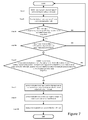
- Figure 7 discloses an embodiment of the method where there is no step VII and thus consequently no automatic movement of the load carrier. Thus the maximal travel speed of the fork-lift is reduced, but no lifting or movement of the load carrier is initiated automatically.
- end is a schematic end, and of course in general the method will continue from beginning.
- a computer program product comprising computer readable code, that when executed on an electronic load carrier unit performs the method according to the above is also part of the subject matter.
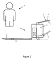
- the disclosed fork-lift truck is disclosed as a low lifter fork-lift truck. But could be a truck having a mast and thus being able to fetch and leave a cargo on a shelf. Also the fork-lift truck can be a fork-lift truck where the operator 10 can travel with it, for example by means of a pivotable platform 8, as disclosed in figure 2 - 5 . or it can be a fork-lift truck not allowing the operator 10 to travel with it.
- the fork-lift truck 1 is preferably an electrically powered fork-lift truck 1 that has an electrical drive motor and an electrical pump motor for pumping hydraulic fluid.
- the fork-lift truck 1 in figure 1 discloses a detection device 2.
- the detection device is in general integrated into the hydraulic system 3 of the fork-lift truck 1. This is preferably done in the main hydraulic block of the system, (not shown). This block in general contains the valves of the hydraulic system and is feed from the hydraulic pump and is in contact with a non-pressurised reservoir of hydraulic fluid.
- the detection device comprises preferably a membrane with for example a thread tension sensor that gives an electric output.
- the fork-lift truck 1 further comprises a load carrier 4 as mentioned above.
- the load carrier is preferably as seen in the Figures 2-5 , a pair of forks.
- the load carrier could be more than two forks and fewer than two forks if desired.
- a load carrier in the form of a ladle would not be applicable for this application as it is intended to be in contact with an external object 20 or a fixed internal object of the fork-lift truck, in another manner than a fork-lift truck.
- a grip device that performs the same tasks as forks but by gripping a load would be included.
- the external object disclosed in the Figures 4 and 5 it should be understood that it need not be an object per se, but could of course be the ground or floor 15 on which the fork-lift truck is supported, for example if the floor 15 is uneven.
- the schematic object 20 should be understood to be an object supported on the ground or for example a shelf on which a load has been laid. It should be understood that the external object 20 could be an object that does not belong to the fork-lift truck but jams the lifting mechanism of this fork-lift truck.
- the discussed a fixed internal object of the fork-lift truck should be understood as being for example a hydraulic piston of the hydraulic system 3 that attains its shortest length, i.e. the least extended state, the load carrier 4 will then be supported at least partially on the rim/or the housing of the hydraulic piston.
- the hydraulic piston is thus being supported on the bottom of the hydraulic cylinder which in turn is supported in the housing 11 of the fork-lift truck.
- the load carrier 4 cannot be lowered further.
- the load carrier 4 will be not only supported by the hydraulic fluid pressure but also mechanically by the fixed object.
- a fixed internal object not generally being a part/element that extends with the hydraulic piston when it extends.
- the fork-lift truck of Figure 2 - 4 has an on board electronic load carrier unit 5.
- This unit is here disclosed as being situated in the handle 7 of the fork-lift truck 1.
- the electronic load carrier unit 5 can be a separated control unit, comprising processor, memory and circuits for performing the discussed method, and housing the computer program product discussed above.
- the load carrier unit 5 can preferably be integrated into a control unit 6 of the fork lift truck 6. This control unit 6 being a main control unit for the fork-lift truck 1.
- the control unit 6 is for this assignment arranged to be able to control and monitor essentially all functions of said fork-lift truck, in particular wherever applicable, lifting, lowering, travel speed, safety functions, horn, weight limitations, height limitations, height pre-sets, acceleration, deceleration, power regeneration, display functions.
- the main control unit 6 is for the industrial truck of Figure 2 - 4 situated in the handle 7 of the fork-lift truck 7.
- the main control unit 6 has an overall control possibility of the fork-lift truck 6.
- the fork-lift truck 6 cannot function if the main control unit 6 is removed from the fork-lift truck 6.
- the control unit 6 can also be positioned at a different position than the handle 7.
- the control unit 6 can be positioned in the housing 11 of the fork-lift truck 1.
- the electronic load carrier unit 5 is an external unit.
- the fork-lift truck 1 must communicate with the load carrier unit 5 by means of a communication device 9.
- This can preferably be a wireless link.
- the communication device 9 comprises thus an antenna and is preferably controlled by the control unit 6 of the fork-lift truck 1.
- the fork-lift truck of Figure 2 discloses the load carrier 4 in a position where it is by the floor/ground 15, for example where the floor ground is uneven.
- Figure 2 is not applicable for the method or the fork-lift truck 1 performing the method on a flat floor.
- the load carrier 4 is in a low or the lowest position, the clearance to the floor/ground is very small and subject any irregularities in the floor/ground 15 the forks will be supported by the ground/floor, or touch it. This is exemplified in Figure 2 .
- An operator 10 uses the fork-lift truck 1 for acquiring a load. After he has delivered the load to a receiver, he will start operating the fork-lift truck to drive it to a new load. The forks may then be positioned as disclosed in Figure 2 . If the forks are positioned in this position the detection device 2 will detect a pressure P that is in a predetermined interval Pval. The reason for this is that the internal pressure in the hydraulic system 3 for at least the section that powers the load carrier 4 is lower as it need not bear the full weight of the load carrier 4. As this situation occurs preferably a time condition t applies in the method discussed above and when this time condition is fulfilled, the following occurs.
- An indication that the load carrier 4 are supported on an object 15/20 is determined and an indication of this is provided to the operator 10, or the indication is transferred from the electronic load carrier unit 5 to the control unit 6 which then is arranged to have the load carrier lifted.
- the operator 10 may decide to manually raise the load carrier 4 when receiving the indication.
- the indication and the raising of the load carrier 4 is ended when P no longer equals Pval, subject a new time condition t2.
- time condition for lifting time t22 as discussed with regard to the method above, that functions as follows, when the operator receives an indication that the load carrier 4 is supported by an external object 15/20 if the operator 10 then raises the load carrier for a determined time period t22, the indication to the operator 10 is set to no longer apply.
- This time condition t22 can also apply for the automated lifting/movement of the load carrier 4 through the control unit 6. Then the load carrier 4 is stopped after t22 is fulfilled.
- t22 is a sum of smaller lifting periods where t22 is an accumulated value. Applicable for both the method the computer program product and the fork-lift truck 1.
- P is thus lower than if the forks are free for travel as disclosed in Figure 3 , where P is not in Pval.
- the limitation to the maximal travel speed is removed if it is determined later in time that the forks-are no longer supported by an external object. This limitation of the travel speed is of course applicable for the method, the computer program product and the fork-lift truck 1.
Landscapes
- Engineering & Computer Science (AREA)
- Structural Engineering (AREA)
- Transportation (AREA)
- Life Sciences & Earth Sciences (AREA)
- Geology (AREA)
- Mechanical Engineering (AREA)
- Civil Engineering (AREA)
- Chemical & Material Sciences (AREA)
- Combustion & Propulsion (AREA)
- Forklifts And Lifting Vehicles (AREA)
Priority Applications (2)
| Application Number | Priority Date | Filing Date | Title |
|---|---|---|---|
| EP14154568.1A EP2905251A1 (fr) | 2014-02-10 | 2014-02-10 | Procédé d'exploitation d'un chariot élévateur à fourche, produit de programme informatique et chariot élévateur à fourche |
| US14/616,665 US20150225218A1 (en) | 2014-02-10 | 2015-02-07 | Method Of Operating A Fork-Lift Truck, Computer Program Product, And A Fork-Lift Truck |
Applications Claiming Priority (1)
| Application Number | Priority Date | Filing Date | Title |
|---|---|---|---|
| EP14154568.1A EP2905251A1 (fr) | 2014-02-10 | 2014-02-10 | Procédé d'exploitation d'un chariot élévateur à fourche, produit de programme informatique et chariot élévateur à fourche |
Publications (1)
| Publication Number | Publication Date |
|---|---|
| EP2905251A1 true EP2905251A1 (fr) | 2015-08-12 |
Family
ID=50070449
Family Applications (1)
| Application Number | Title | Priority Date | Filing Date |
|---|---|---|---|
| EP14154568.1A Withdrawn EP2905251A1 (fr) | 2014-02-10 | 2014-02-10 | Procédé d'exploitation d'un chariot élévateur à fourche, produit de programme informatique et chariot élévateur à fourche |
Country Status (2)
| Country | Link |
|---|---|
| US (1) | US20150225218A1 (fr) |
| EP (1) | EP2905251A1 (fr) |
Families Citing this family (6)
| Publication number | Priority date | Publication date | Assignee | Title |
|---|---|---|---|---|
| DE102015111178A1 (de) * | 2015-07-10 | 2017-01-12 | Jungheinrich Aktiengesellschaft | Standplattform für ein Flurförderzeug |
| CN107735761B (zh) | 2015-07-17 | 2022-03-04 | 克朗设备公司 | 用于工业车辆的具有图形用户界面的处理设备 |
| US9505595B1 (en) * | 2015-11-06 | 2016-11-29 | James Nelson Smith | Rapid delivery pallet jack system |
| SE541740C2 (en) * | 2016-04-19 | 2019-12-03 | Toyota Mat Handling Manufacturing Sweden Ab | A fork-lift truck comprising a sensor device for controlling predetermined operational parameters |
| EP4180928A1 (fr) | 2016-11-22 | 2023-05-17 | Crown Equipment Corporation | Dispositif d'interface utilisateur pour véhicule industriel |
| NL2019033B1 (nl) | 2017-06-08 | 2018-12-17 | Ravas Europe B V | Inrichting voor het verplaatsen van een last alsmede een heforgaan daarvoor |
Citations (3)
| Publication number | Priority date | Publication date | Assignee | Title |
|---|---|---|---|---|
| US5462136A (en) * | 1994-03-03 | 1995-10-31 | The Raymond Corporation | Prevention of slack lift chains on a man-up lift truck |
| US20070239312A1 (en) * | 2006-04-10 | 2007-10-11 | Andersen Scott P | System and method for tracking inventory movement using a material handling device |
| US7287625B1 (en) * | 2004-02-19 | 2007-10-30 | Harris Brian L | Forklift safety sensor and control system |
Family Cites Families (3)
| Publication number | Priority date | Publication date | Assignee | Title |
|---|---|---|---|---|
| US4839835A (en) * | 1984-04-27 | 1989-06-13 | Hagenbuch Roy George Le | Apparatus and method responsive to the on-board measuring of the load carried by a truck body |
| US5995001A (en) * | 1997-07-09 | 1999-11-30 | Crown Equipment Corporation | Method and apparatus for providing operating information to an operator of a fork lift truck |
| US9567195B2 (en) * | 2013-05-13 | 2017-02-14 | Hall David R | Load distribution management for groups of motorized lifting devices |
-
2014
- 2014-02-10 EP EP14154568.1A patent/EP2905251A1/fr not_active Withdrawn
-
2015
- 2015-02-07 US US14/616,665 patent/US20150225218A1/en not_active Abandoned
Patent Citations (3)
| Publication number | Priority date | Publication date | Assignee | Title |
|---|---|---|---|---|
| US5462136A (en) * | 1994-03-03 | 1995-10-31 | The Raymond Corporation | Prevention of slack lift chains on a man-up lift truck |
| US7287625B1 (en) * | 2004-02-19 | 2007-10-30 | Harris Brian L | Forklift safety sensor and control system |
| US20070239312A1 (en) * | 2006-04-10 | 2007-10-11 | Andersen Scott P | System and method for tracking inventory movement using a material handling device |
Also Published As
| Publication number | Publication date |
|---|---|
| US20150225218A1 (en) | 2015-08-13 |
Similar Documents
| Publication | Publication Date | Title |
|---|---|---|
| US20150225218A1 (en) | Method Of Operating A Fork-Lift Truck, Computer Program Product, And A Fork-Lift Truck | |
| KR102300161B1 (ko) | 광학적 적재물 감지 구조물을 구비한 리프트 트럭 | |
| US8230976B2 (en) | Pallet truck with calculated fork carriage height | |
| EP3106423A1 (fr) | Systèmes et procédés de détermination du poids et de commande de vitesse en boucle fermée | |
| CN113329967B (zh) | 链条松弛检测系统 | |
| KR20140005285A (ko) | 리프트 모터 속도로부터 가동 조립체의 속도를 추정하는 물류 취급 차량 | |
| US10343883B2 (en) | Lifting device of an industrial truck and method for setting down a load carried on load handling means of an industrial truck on a surface | |
| JP5596941B2 (ja) | 産業車両用フォーク昇降制御機構 | |
| JP2002020093A (ja) | 荷物昇降装置 | |
| CN112824312A (zh) | 基于任务分类的物料搬运车辆行为修改 | |
| EP2955149B1 (fr) | Procédé d'exploitation d'un chariot élévateur à fourche, chariot élévateur à fourche, produit de programme informatique et procédé de modification de chariot élévateur à fourche | |
| JP5453857B2 (ja) | 荷役車両 | |
| WO2019027321A1 (fr) | Dispositif de protection de charge de palette, chariot élévateur à fourche équipé de celui-ci et procédé de protection de charge sur une palette | |
| JP2014069914A (ja) | アウトリガジャッキの伸長状態監視装置 | |
| JP2006298638A (ja) | フォークリフト | |
| CN116902865A (zh) | 具有承载能力检查装置的地面运输工具 | |
| JPH10203798A (ja) | 車両の荷役制御装置 | |
| JP2012166903A (ja) | リフトチェーンのメンテナンス時期告知装置 | |
| IT202000016045A1 (it) | Carrello industriale con controllo di stabilità migliorato | |
| JP2022164175A (ja) | 積載量測定システムおよび運搬車 | |
| JP2007217071A (ja) | 昇降装置 | |
| CN114684753A (zh) | 叉车货叉高度的控制方法、装置、系统和叉车 | |
| JP2003238091A (ja) | フォークリフト | |
| JPH04303398A (ja) | フォークリフトの制御装置 | |
| JP2002029691A (ja) | 荷役車両 |
Legal Events
| Date | Code | Title | Description |
|---|---|---|---|
| PUAI | Public reference made under article 153(3) epc to a published international application that has entered the european phase |
Free format text: ORIGINAL CODE: 0009012 |
|
| AK | Designated contracting states |
Kind code of ref document: A1 Designated state(s): AL AT BE BG CH CY CZ DE DK EE ES FI FR GB GR HR HU IE IS IT LI LT LU LV MC MK MT NL NO PL PT RO RS SE SI SK SM TR |
|
| AX | Request for extension of the european patent |
Extension state: BA ME |
|
| 17P | Request for examination filed |
Effective date: 20160209 |
|
| RBV | Designated contracting states (corrected) |
Designated state(s): AL AT BE BG CH CY CZ DE DK EE ES FI FR GB GR HR HU IE IS IT LI LT LU LV MC MK MT NL NO PL PT RO RS SE SI SK SM TR |
|
| 17Q | First examination report despatched |
Effective date: 20160823 |
|
| STAA | Information on the status of an ep patent application or granted ep patent |
Free format text: STATUS: EXAMINATION IS IN PROGRESS |
|
| STAA | Information on the status of an ep patent application or granted ep patent |
Free format text: STATUS: THE APPLICATION IS DEEMED TO BE WITHDRAWN |
|
| 18D | Application deemed to be withdrawn |
Effective date: 20170103 |