EP2905161A1 - Saddled electric vehicle - Google Patents
Saddled electric vehicle Download PDFInfo
- Publication number
- EP2905161A1 EP2905161A1 EP13843645.6A EP13843645A EP2905161A1 EP 2905161 A1 EP2905161 A1 EP 2905161A1 EP 13843645 A EP13843645 A EP 13843645A EP 2905161 A1 EP2905161 A1 EP 2905161A1
- Authority
- EP
- European Patent Office
- Prior art keywords
- power supply
- vehicle width
- frame
- supply unit
- vehicle
- Prior art date
- Legal status (The legal status is an assumption and is not a legal conclusion. Google has not performed a legal analysis and makes no representation as to the accuracy of the status listed.)
- Granted
Links
Images




Classifications
-
- B—PERFORMING OPERATIONS; TRANSPORTING
- B60—VEHICLES IN GENERAL
- B60K—ARRANGEMENT OR MOUNTING OF PROPULSION UNITS OR OF TRANSMISSIONS IN VEHICLES; ARRANGEMENT OR MOUNTING OF PLURAL DIVERSE PRIME-MOVERS IN VEHICLES; AUXILIARY DRIVES FOR VEHICLES; INSTRUMENTATION OR DASHBOARDS FOR VEHICLES; ARRANGEMENTS IN CONNECTION WITH COOLING, AIR INTAKE, GAS EXHAUST OR FUEL SUPPLY OF PROPULSION UNITS IN VEHICLES
- B60K1/00—Arrangement or mounting of electrical propulsion units
- B60K1/04—Arrangement or mounting of electrical propulsion units of the electric storage means for propulsion
-
- B—PERFORMING OPERATIONS; TRANSPORTING
- B60—VEHICLES IN GENERAL
- B60L—PROPULSION OF ELECTRICALLY-PROPELLED VEHICLES; SUPPLYING ELECTRIC POWER FOR AUXILIARY EQUIPMENT OF ELECTRICALLY-PROPELLED VEHICLES; ELECTRODYNAMIC BRAKE SYSTEMS FOR VEHICLES IN GENERAL; MAGNETIC SUSPENSION OR LEVITATION FOR VEHICLES; MONITORING OPERATING VARIABLES OF ELECTRICALLY-PROPELLED VEHICLES; ELECTRIC SAFETY DEVICES FOR ELECTRICALLY-PROPELLED VEHICLES
- B60L3/00—Electric devices on electrically-propelled vehicles for safety purposes; Monitoring operating variables, e.g. speed, deceleration or energy consumption
- B60L3/0023—Detecting, eliminating, remedying or compensating for drive train abnormalities, e.g. failures within the drive train
- B60L3/0046—Detecting, eliminating, remedying or compensating for drive train abnormalities, e.g. failures within the drive train relating to electric energy storage systems, e.g. batteries or capacitors
-
- B—PERFORMING OPERATIONS; TRANSPORTING
- B60—VEHICLES IN GENERAL
- B60L—PROPULSION OF ELECTRICALLY-PROPELLED VEHICLES; SUPPLYING ELECTRIC POWER FOR AUXILIARY EQUIPMENT OF ELECTRICALLY-PROPELLED VEHICLES; ELECTRODYNAMIC BRAKE SYSTEMS FOR VEHICLES IN GENERAL; MAGNETIC SUSPENSION OR LEVITATION FOR VEHICLES; MONITORING OPERATING VARIABLES OF ELECTRICALLY-PROPELLED VEHICLES; ELECTRIC SAFETY DEVICES FOR ELECTRICALLY-PROPELLED VEHICLES
- B60L3/00—Electric devices on electrically-propelled vehicles for safety purposes; Monitoring operating variables, e.g. speed, deceleration or energy consumption
- B60L3/12—Recording operating variables ; Monitoring of operating variables
-
- B—PERFORMING OPERATIONS; TRANSPORTING
- B60—VEHICLES IN GENERAL
- B60L—PROPULSION OF ELECTRICALLY-PROPELLED VEHICLES; SUPPLYING ELECTRIC POWER FOR AUXILIARY EQUIPMENT OF ELECTRICALLY-PROPELLED VEHICLES; ELECTRODYNAMIC BRAKE SYSTEMS FOR VEHICLES IN GENERAL; MAGNETIC SUSPENSION OR LEVITATION FOR VEHICLES; MONITORING OPERATING VARIABLES OF ELECTRICALLY-PROPELLED VEHICLES; ELECTRIC SAFETY DEVICES FOR ELECTRICALLY-PROPELLED VEHICLES
- B60L50/00—Electric propulsion with power supplied within the vehicle
- B60L50/50—Electric propulsion with power supplied within the vehicle using propulsion power supplied by batteries or fuel cells
- B60L50/51—Electric propulsion with power supplied within the vehicle using propulsion power supplied by batteries or fuel cells characterised by AC-motors
-
- B—PERFORMING OPERATIONS; TRANSPORTING
- B60—VEHICLES IN GENERAL
- B60L—PROPULSION OF ELECTRICALLY-PROPELLED VEHICLES; SUPPLYING ELECTRIC POWER FOR AUXILIARY EQUIPMENT OF ELECTRICALLY-PROPELLED VEHICLES; ELECTRODYNAMIC BRAKE SYSTEMS FOR VEHICLES IN GENERAL; MAGNETIC SUSPENSION OR LEVITATION FOR VEHICLES; MONITORING OPERATING VARIABLES OF ELECTRICALLY-PROPELLED VEHICLES; ELECTRIC SAFETY DEVICES FOR ELECTRICALLY-PROPELLED VEHICLES
- B60L50/00—Electric propulsion with power supplied within the vehicle
- B60L50/50—Electric propulsion with power supplied within the vehicle using propulsion power supplied by batteries or fuel cells
- B60L50/60—Electric propulsion with power supplied within the vehicle using propulsion power supplied by batteries or fuel cells using power supplied by batteries
- B60L50/64—Constructional details of batteries specially adapted for electric vehicles
-
- B—PERFORMING OPERATIONS; TRANSPORTING
- B60—VEHICLES IN GENERAL
- B60L—PROPULSION OF ELECTRICALLY-PROPELLED VEHICLES; SUPPLYING ELECTRIC POWER FOR AUXILIARY EQUIPMENT OF ELECTRICALLY-PROPELLED VEHICLES; ELECTRODYNAMIC BRAKE SYSTEMS FOR VEHICLES IN GENERAL; MAGNETIC SUSPENSION OR LEVITATION FOR VEHICLES; MONITORING OPERATING VARIABLES OF ELECTRICALLY-PROPELLED VEHICLES; ELECTRIC SAFETY DEVICES FOR ELECTRICALLY-PROPELLED VEHICLES
- B60L50/00—Electric propulsion with power supplied within the vehicle
- B60L50/50—Electric propulsion with power supplied within the vehicle using propulsion power supplied by batteries or fuel cells
- B60L50/60—Electric propulsion with power supplied within the vehicle using propulsion power supplied by batteries or fuel cells using power supplied by batteries
- B60L50/66—Arrangements of batteries
-
- B—PERFORMING OPERATIONS; TRANSPORTING
- B60—VEHICLES IN GENERAL
- B60L—PROPULSION OF ELECTRICALLY-PROPELLED VEHICLES; SUPPLYING ELECTRIC POWER FOR AUXILIARY EQUIPMENT OF ELECTRICALLY-PROPELLED VEHICLES; ELECTRODYNAMIC BRAKE SYSTEMS FOR VEHICLES IN GENERAL; MAGNETIC SUSPENSION OR LEVITATION FOR VEHICLES; MONITORING OPERATING VARIABLES OF ELECTRICALLY-PROPELLED VEHICLES; ELECTRIC SAFETY DEVICES FOR ELECTRICALLY-PROPELLED VEHICLES
- B60L53/00—Methods of charging batteries, specially adapted for electric vehicles; Charging stations or on-board charging equipment therefor; Exchange of energy storage elements in electric vehicles
- B60L53/10—Methods of charging batteries, specially adapted for electric vehicles; Charging stations or on-board charging equipment therefor; Exchange of energy storage elements in electric vehicles characterised by the energy transfer between the charging station and the vehicle
- B60L53/14—Conductive energy transfer
- B60L53/16—Connectors, e.g. plugs or sockets, specially adapted for charging electric vehicles
-
- B—PERFORMING OPERATIONS; TRANSPORTING
- B60—VEHICLES IN GENERAL
- B60L—PROPULSION OF ELECTRICALLY-PROPELLED VEHICLES; SUPPLYING ELECTRIC POWER FOR AUXILIARY EQUIPMENT OF ELECTRICALLY-PROPELLED VEHICLES; ELECTRODYNAMIC BRAKE SYSTEMS FOR VEHICLES IN GENERAL; MAGNETIC SUSPENSION OR LEVITATION FOR VEHICLES; MONITORING OPERATING VARIABLES OF ELECTRICALLY-PROPELLED VEHICLES; ELECTRIC SAFETY DEVICES FOR ELECTRICALLY-PROPELLED VEHICLES
- B60L53/00—Methods of charging batteries, specially adapted for electric vehicles; Charging stations or on-board charging equipment therefor; Exchange of energy storage elements in electric vehicles
- B60L53/30—Constructional details of charging stations
- B60L53/305—Communication interfaces
-
- B—PERFORMING OPERATIONS; TRANSPORTING
- B60—VEHICLES IN GENERAL
- B60L—PROPULSION OF ELECTRICALLY-PROPELLED VEHICLES; SUPPLYING ELECTRIC POWER FOR AUXILIARY EQUIPMENT OF ELECTRICALLY-PROPELLED VEHICLES; ELECTRODYNAMIC BRAKE SYSTEMS FOR VEHICLES IN GENERAL; MAGNETIC SUSPENSION OR LEVITATION FOR VEHICLES; MONITORING OPERATING VARIABLES OF ELECTRICALLY-PROPELLED VEHICLES; ELECTRIC SAFETY DEVICES FOR ELECTRICALLY-PROPELLED VEHICLES
- B60L53/00—Methods of charging batteries, specially adapted for electric vehicles; Charging stations or on-board charging equipment therefor; Exchange of energy storage elements in electric vehicles
- B60L53/80—Exchanging energy storage elements, e.g. removable batteries
-
- B—PERFORMING OPERATIONS; TRANSPORTING
- B60—VEHICLES IN GENERAL
- B60L—PROPULSION OF ELECTRICALLY-PROPELLED VEHICLES; SUPPLYING ELECTRIC POWER FOR AUXILIARY EQUIPMENT OF ELECTRICALLY-PROPELLED VEHICLES; ELECTRODYNAMIC BRAKE SYSTEMS FOR VEHICLES IN GENERAL; MAGNETIC SUSPENSION OR LEVITATION FOR VEHICLES; MONITORING OPERATING VARIABLES OF ELECTRICALLY-PROPELLED VEHICLES; ELECTRIC SAFETY DEVICES FOR ELECTRICALLY-PROPELLED VEHICLES
- B60L58/00—Methods or circuit arrangements for monitoring or controlling batteries or fuel cells, specially adapted for electric vehicles
- B60L58/10—Methods or circuit arrangements for monitoring or controlling batteries or fuel cells, specially adapted for electric vehicles for monitoring or controlling batteries
- B60L58/12—Methods or circuit arrangements for monitoring or controlling batteries or fuel cells, specially adapted for electric vehicles for monitoring or controlling batteries responding to state of charge [SoC]
- B60L58/14—Preventing excessive discharging
-
- B—PERFORMING OPERATIONS; TRANSPORTING
- B60—VEHICLES IN GENERAL
- B60L—PROPULSION OF ELECTRICALLY-PROPELLED VEHICLES; SUPPLYING ELECTRIC POWER FOR AUXILIARY EQUIPMENT OF ELECTRICALLY-PROPELLED VEHICLES; ELECTRODYNAMIC BRAKE SYSTEMS FOR VEHICLES IN GENERAL; MAGNETIC SUSPENSION OR LEVITATION FOR VEHICLES; MONITORING OPERATING VARIABLES OF ELECTRICALLY-PROPELLED VEHICLES; ELECTRIC SAFETY DEVICES FOR ELECTRICALLY-PROPELLED VEHICLES
- B60L58/00—Methods or circuit arrangements for monitoring or controlling batteries or fuel cells, specially adapted for electric vehicles
- B60L58/10—Methods or circuit arrangements for monitoring or controlling batteries or fuel cells, specially adapted for electric vehicles for monitoring or controlling batteries
- B60L58/18—Methods or circuit arrangements for monitoring or controlling batteries or fuel cells, specially adapted for electric vehicles for monitoring or controlling batteries of two or more battery modules
- B60L58/20—Methods or circuit arrangements for monitoring or controlling batteries or fuel cells, specially adapted for electric vehicles for monitoring or controlling batteries of two or more battery modules having different nominal voltages
-
- B—PERFORMING OPERATIONS; TRANSPORTING
- B62—LAND VEHICLES FOR TRAVELLING OTHERWISE THAN ON RAILS
- B62D—MOTOR VEHICLES; TRAILERS
- B62D65/00—Designing, manufacturing, e.g. assembling, facilitating disassembly, or structurally modifying motor vehicles or trailers, not otherwise provided for
- B62D65/005—Inspection and final control devices
-
- B—PERFORMING OPERATIONS; TRANSPORTING
- B62—LAND VEHICLES FOR TRAVELLING OTHERWISE THAN ON RAILS
- B62J—CYCLE SADDLES OR SEATS; AUXILIARY DEVICES OR ACCESSORIES SPECIALLY ADAPTED TO CYCLES AND NOT OTHERWISE PROVIDED FOR, e.g. ARTICLE CARRIERS OR CYCLE PROTECTORS
- B62J43/00—Arrangements of batteries
- B62J43/10—Arrangements of batteries for propulsion
- B62J43/16—Arrangements of batteries for propulsion on motorcycles or the like
-
- B—PERFORMING OPERATIONS; TRANSPORTING
- B62—LAND VEHICLES FOR TRAVELLING OTHERWISE THAN ON RAILS
- B62J—CYCLE SADDLES OR SEATS; AUXILIARY DEVICES OR ACCESSORIES SPECIALLY ADAPTED TO CYCLES AND NOT OTHERWISE PROVIDED FOR, e.g. ARTICLE CARRIERS OR CYCLE PROTECTORS
- B62J43/00—Arrangements of batteries
- B62J43/20—Arrangements of batteries characterised by the mounting
- B62J43/28—Arrangements of batteries characterised by the mounting hidden within the cycle frame
-
- B—PERFORMING OPERATIONS; TRANSPORTING
- B62—LAND VEHICLES FOR TRAVELLING OTHERWISE THAN ON RAILS
- B62K—CYCLES; CYCLE FRAMES; CYCLE STEERING DEVICES; RIDER-OPERATED TERMINAL CONTROLS SPECIALLY ADAPTED FOR CYCLES; CYCLE AXLE SUSPENSIONS; CYCLE SIDECARS, FORECARS, OR THE LIKE
- B62K11/00—Motorcycles, engine-assisted cycles or motor scooters with one or two wheels
- B62K11/02—Frames
- B62K11/04—Frames characterised by the engine being between front and rear wheels
-
- B—PERFORMING OPERATIONS; TRANSPORTING
- B62—LAND VEHICLES FOR TRAVELLING OTHERWISE THAN ON RAILS
- B62K—CYCLES; CYCLE FRAMES; CYCLE STEERING DEVICES; RIDER-OPERATED TERMINAL CONTROLS SPECIALLY ADAPTED FOR CYCLES; CYCLE AXLE SUSPENSIONS; CYCLE SIDECARS, FORECARS, OR THE LIKE
- B62K19/00—Cycle frames
- B62K19/30—Frame parts shaped to receive other cycle parts or accessories
-
- B—PERFORMING OPERATIONS; TRANSPORTING
- B62—LAND VEHICLES FOR TRAVELLING OTHERWISE THAN ON RAILS
- B62K—CYCLES; CYCLE FRAMES; CYCLE STEERING DEVICES; RIDER-OPERATED TERMINAL CONTROLS SPECIALLY ADAPTED FOR CYCLES; CYCLE AXLE SUSPENSIONS; CYCLE SIDECARS, FORECARS, OR THE LIKE
- B62K19/00—Cycle frames
- B62K19/30—Frame parts shaped to receive other cycle parts or accessories
- B62K19/34—Bottom brackets
-
- B—PERFORMING OPERATIONS; TRANSPORTING
- B62—LAND VEHICLES FOR TRAVELLING OTHERWISE THAN ON RAILS
- B62K—CYCLES; CYCLE FRAMES; CYCLE STEERING DEVICES; RIDER-OPERATED TERMINAL CONTROLS SPECIALLY ADAPTED FOR CYCLES; CYCLE AXLE SUSPENSIONS; CYCLE SIDECARS, FORECARS, OR THE LIKE
- B62K25/00—Axle suspensions
- B62K25/04—Axle suspensions for mounting axles resiliently on cycle frame or fork
- B62K25/28—Axle suspensions for mounting axles resiliently on cycle frame or fork with pivoted chain-stay
- B62K25/283—Axle suspensions for mounting axles resiliently on cycle frame or fork with pivoted chain-stay for cycles without a pedal crank, e.g. motorcycles
-
- B—PERFORMING OPERATIONS; TRANSPORTING
- B62—LAND VEHICLES FOR TRAVELLING OTHERWISE THAN ON RAILS
- B62M—RIDER PROPULSION OF WHEELED VEHICLES OR SLEDGES; POWERED PROPULSION OF SLEDGES OR SINGLE-TRACK CYCLES; TRANSMISSIONS SPECIALLY ADAPTED FOR SUCH VEHICLES
- B62M7/00—Motorcycles characterised by position of motor or engine
- B62M7/02—Motorcycles characterised by position of motor or engine with engine between front and rear wheels
-
- G—PHYSICS
- G01—MEASURING; TESTING
- G01M—TESTING STATIC OR DYNAMIC BALANCE OF MACHINES OR STRUCTURES; TESTING OF STRUCTURES OR APPARATUS, NOT OTHERWISE PROVIDED FOR
- G01M17/00—Testing of vehicles
- G01M17/007—Wheeled or endless-tracked vehicles
-
- H—ELECTRICITY
- H01—ELECTRIC ELEMENTS
- H01M—PROCESSES OR MEANS, e.g. BATTERIES, FOR THE DIRECT CONVERSION OF CHEMICAL ENERGY INTO ELECTRICAL ENERGY
- H01M10/00—Secondary cells; Manufacture thereof
- H01M10/42—Methods or arrangements for servicing or maintenance of secondary cells or secondary half-cells
- H01M10/48—Accumulators combined with arrangements for measuring, testing or indicating the condition of cells, e.g. the level or density of the electrolyte
-
- H—ELECTRICITY
- H01—ELECTRIC ELEMENTS
- H01M—PROCESSES OR MEANS, e.g. BATTERIES, FOR THE DIRECT CONVERSION OF CHEMICAL ENERGY INTO ELECTRICAL ENERGY
- H01M50/00—Constructional details or processes of manufacture of the non-active parts of electrochemical cells other than fuel cells, e.g. hybrid cells
- H01M50/20—Mountings; Secondary casings or frames; Racks, modules or packs; Suspension devices; Shock absorbers; Transport or carrying devices; Holders
- H01M50/204—Racks, modules or packs for multiple batteries or multiple cells
-
- H—ELECTRICITY
- H01—ELECTRIC ELEMENTS
- H01M—PROCESSES OR MEANS, e.g. BATTERIES, FOR THE DIRECT CONVERSION OF CHEMICAL ENERGY INTO ELECTRICAL ENERGY
- H01M50/00—Constructional details or processes of manufacture of the non-active parts of electrochemical cells other than fuel cells, e.g. hybrid cells
- H01M50/20—Mountings; Secondary casings or frames; Racks, modules or packs; Suspension devices; Shock absorbers; Transport or carrying devices; Holders
- H01M50/249—Mountings; Secondary casings or frames; Racks, modules or packs; Suspension devices; Shock absorbers; Transport or carrying devices; Holders specially adapted for aircraft or vehicles, e.g. cars or trains
-
- B—PERFORMING OPERATIONS; TRANSPORTING
- B60—VEHICLES IN GENERAL
- B60K—ARRANGEMENT OR MOUNTING OF PROPULSION UNITS OR OF TRANSMISSIONS IN VEHICLES; ARRANGEMENT OR MOUNTING OF PLURAL DIVERSE PRIME-MOVERS IN VEHICLES; AUXILIARY DRIVES FOR VEHICLES; INSTRUMENTATION OR DASHBOARDS FOR VEHICLES; ARRANGEMENTS IN CONNECTION WITH COOLING, AIR INTAKE, GAS EXHAUST OR FUEL SUPPLY OF PROPULSION UNITS IN VEHICLES
- B60K1/00—Arrangement or mounting of electrical propulsion units
- B60K1/04—Arrangement or mounting of electrical propulsion units of the electric storage means for propulsion
- B60K2001/0455—Removal or replacement of the energy storages
-
- B—PERFORMING OPERATIONS; TRANSPORTING
- B60—VEHICLES IN GENERAL
- B60K—ARRANGEMENT OR MOUNTING OF PROPULSION UNITS OR OF TRANSMISSIONS IN VEHICLES; ARRANGEMENT OR MOUNTING OF PLURAL DIVERSE PRIME-MOVERS IN VEHICLES; AUXILIARY DRIVES FOR VEHICLES; INSTRUMENTATION OR DASHBOARDS FOR VEHICLES; ARRANGEMENTS IN CONNECTION WITH COOLING, AIR INTAKE, GAS EXHAUST OR FUEL SUPPLY OF PROPULSION UNITS IN VEHICLES
- B60K1/00—Arrangement or mounting of electrical propulsion units
- B60K1/04—Arrangement or mounting of electrical propulsion units of the electric storage means for propulsion
- B60K2001/0455—Removal or replacement of the energy storages
- B60K2001/0461—Removal or replacement of the energy storages from the side
-
- B—PERFORMING OPERATIONS; TRANSPORTING
- B60—VEHICLES IN GENERAL
- B60L—PROPULSION OF ELECTRICALLY-PROPELLED VEHICLES; SUPPLYING ELECTRIC POWER FOR AUXILIARY EQUIPMENT OF ELECTRICALLY-PROPELLED VEHICLES; ELECTRODYNAMIC BRAKE SYSTEMS FOR VEHICLES IN GENERAL; MAGNETIC SUSPENSION OR LEVITATION FOR VEHICLES; MONITORING OPERATING VARIABLES OF ELECTRICALLY-PROPELLED VEHICLES; ELECTRIC SAFETY DEVICES FOR ELECTRICALLY-PROPELLED VEHICLES
- B60L2200/00—Type of vehicles
- B60L2200/12—Bikes
-
- B—PERFORMING OPERATIONS; TRANSPORTING
- B60—VEHICLES IN GENERAL
- B60L—PROPULSION OF ELECTRICALLY-PROPELLED VEHICLES; SUPPLYING ELECTRIC POWER FOR AUXILIARY EQUIPMENT OF ELECTRICALLY-PROPELLED VEHICLES; ELECTRODYNAMIC BRAKE SYSTEMS FOR VEHICLES IN GENERAL; MAGNETIC SUSPENSION OR LEVITATION FOR VEHICLES; MONITORING OPERATING VARIABLES OF ELECTRICALLY-PROPELLED VEHICLES; ELECTRIC SAFETY DEVICES FOR ELECTRICALLY-PROPELLED VEHICLES
- B60L2240/00—Control parameters of input or output; Target parameters
- B60L2240/40—Drive Train control parameters
- B60L2240/54—Drive Train control parameters related to batteries
- B60L2240/545—Temperature
-
- B—PERFORMING OPERATIONS; TRANSPORTING
- B60—VEHICLES IN GENERAL
- B60L—PROPULSION OF ELECTRICALLY-PROPELLED VEHICLES; SUPPLYING ELECTRIC POWER FOR AUXILIARY EQUIPMENT OF ELECTRICALLY-PROPELLED VEHICLES; ELECTRODYNAMIC BRAKE SYSTEMS FOR VEHICLES IN GENERAL; MAGNETIC SUSPENSION OR LEVITATION FOR VEHICLES; MONITORING OPERATING VARIABLES OF ELECTRICALLY-PROPELLED VEHICLES; ELECTRIC SAFETY DEVICES FOR ELECTRICALLY-PROPELLED VEHICLES
- B60L2270/00—Problem solutions or means not otherwise provided for
- B60L2270/40—Problem solutions or means not otherwise provided for related to technical updates when adding new parts or software
-
- B—PERFORMING OPERATIONS; TRANSPORTING
- B60—VEHICLES IN GENERAL
- B60Y—INDEXING SCHEME RELATING TO ASPECTS CROSS-CUTTING VEHICLE TECHNOLOGY
- B60Y2200/00—Type of vehicle
- B60Y2200/10—Road Vehicles
- B60Y2200/12—Motorcycles, Trikes; Quads; Scooters
-
- B—PERFORMING OPERATIONS; TRANSPORTING
- B62—LAND VEHICLES FOR TRAVELLING OTHERWISE THAN ON RAILS
- B62K—CYCLES; CYCLE FRAMES; CYCLE STEERING DEVICES; RIDER-OPERATED TERMINAL CONTROLS SPECIALLY ADAPTED FOR CYCLES; CYCLE AXLE SUSPENSIONS; CYCLE SIDECARS, FORECARS, OR THE LIKE
- B62K2204/00—Adaptations for driving cycles by electric motor
-
- H—ELECTRICITY
- H01—ELECTRIC ELEMENTS
- H01M—PROCESSES OR MEANS, e.g. BATTERIES, FOR THE DIRECT CONVERSION OF CHEMICAL ENERGY INTO ELECTRICAL ENERGY
- H01M2220/00—Batteries for particular applications
- H01M2220/20—Batteries in motive systems, e.g. vehicle, ship, plane
-
- Y—GENERAL TAGGING OF NEW TECHNOLOGICAL DEVELOPMENTS; GENERAL TAGGING OF CROSS-SECTIONAL TECHNOLOGIES SPANNING OVER SEVERAL SECTIONS OF THE IPC; TECHNICAL SUBJECTS COVERED BY FORMER USPC CROSS-REFERENCE ART COLLECTIONS [XRACs] AND DIGESTS
- Y02—TECHNOLOGIES OR APPLICATIONS FOR MITIGATION OR ADAPTATION AGAINST CLIMATE CHANGE
- Y02E—REDUCTION OF GREENHOUSE GAS [GHG] EMISSIONS, RELATED TO ENERGY GENERATION, TRANSMISSION OR DISTRIBUTION
- Y02E60/00—Enabling technologies; Technologies with a potential or indirect contribution to GHG emissions mitigation
- Y02E60/10—Energy storage using batteries
-
- Y—GENERAL TAGGING OF NEW TECHNOLOGICAL DEVELOPMENTS; GENERAL TAGGING OF CROSS-SECTIONAL TECHNOLOGIES SPANNING OVER SEVERAL SECTIONS OF THE IPC; TECHNICAL SUBJECTS COVERED BY FORMER USPC CROSS-REFERENCE ART COLLECTIONS [XRACs] AND DIGESTS
- Y02—TECHNOLOGIES OR APPLICATIONS FOR MITIGATION OR ADAPTATION AGAINST CLIMATE CHANGE
- Y02T—CLIMATE CHANGE MITIGATION TECHNOLOGIES RELATED TO TRANSPORTATION
- Y02T10/00—Road transport of goods or passengers
- Y02T10/60—Other road transportation technologies with climate change mitigation effect
- Y02T10/70—Energy storage systems for electromobility, e.g. batteries
-
- Y—GENERAL TAGGING OF NEW TECHNOLOGICAL DEVELOPMENTS; GENERAL TAGGING OF CROSS-SECTIONAL TECHNOLOGIES SPANNING OVER SEVERAL SECTIONS OF THE IPC; TECHNICAL SUBJECTS COVERED BY FORMER USPC CROSS-REFERENCE ART COLLECTIONS [XRACs] AND DIGESTS
- Y02—TECHNOLOGIES OR APPLICATIONS FOR MITIGATION OR ADAPTATION AGAINST CLIMATE CHANGE
- Y02T—CLIMATE CHANGE MITIGATION TECHNOLOGIES RELATED TO TRANSPORTATION
- Y02T10/00—Road transport of goods or passengers
- Y02T10/60—Other road transportation technologies with climate change mitigation effect
- Y02T10/7072—Electromobility specific charging systems or methods for batteries, ultracapacitors, supercapacitors or double-layer capacitors
-
- Y—GENERAL TAGGING OF NEW TECHNOLOGICAL DEVELOPMENTS; GENERAL TAGGING OF CROSS-SECTIONAL TECHNOLOGIES SPANNING OVER SEVERAL SECTIONS OF THE IPC; TECHNICAL SUBJECTS COVERED BY FORMER USPC CROSS-REFERENCE ART COLLECTIONS [XRACs] AND DIGESTS
- Y02—TECHNOLOGIES OR APPLICATIONS FOR MITIGATION OR ADAPTATION AGAINST CLIMATE CHANGE
- Y02T—CLIMATE CHANGE MITIGATION TECHNOLOGIES RELATED TO TRANSPORTATION
- Y02T90/00—Enabling technologies or technologies with a potential or indirect contribution to GHG emissions mitigation
- Y02T90/10—Technologies relating to charging of electric vehicles
- Y02T90/12—Electric charging stations
-
- Y—GENERAL TAGGING OF NEW TECHNOLOGICAL DEVELOPMENTS; GENERAL TAGGING OF CROSS-SECTIONAL TECHNOLOGIES SPANNING OVER SEVERAL SECTIONS OF THE IPC; TECHNICAL SUBJECTS COVERED BY FORMER USPC CROSS-REFERENCE ART COLLECTIONS [XRACs] AND DIGESTS
- Y02—TECHNOLOGIES OR APPLICATIONS FOR MITIGATION OR ADAPTATION AGAINST CLIMATE CHANGE
- Y02T—CLIMATE CHANGE MITIGATION TECHNOLOGIES RELATED TO TRANSPORTATION
- Y02T90/00—Enabling technologies or technologies with a potential or indirect contribution to GHG emissions mitigation
- Y02T90/10—Technologies relating to charging of electric vehicles
- Y02T90/14—Plug-in electric vehicles
-
- Y—GENERAL TAGGING OF NEW TECHNOLOGICAL DEVELOPMENTS; GENERAL TAGGING OF CROSS-SECTIONAL TECHNOLOGIES SPANNING OVER SEVERAL SECTIONS OF THE IPC; TECHNICAL SUBJECTS COVERED BY FORMER USPC CROSS-REFERENCE ART COLLECTIONS [XRACs] AND DIGESTS
- Y02—TECHNOLOGIES OR APPLICATIONS FOR MITIGATION OR ADAPTATION AGAINST CLIMATE CHANGE
- Y02T—CLIMATE CHANGE MITIGATION TECHNOLOGIES RELATED TO TRANSPORTATION
- Y02T90/00—Enabling technologies or technologies with a potential or indirect contribution to GHG emissions mitigation
- Y02T90/10—Technologies relating to charging of electric vehicles
- Y02T90/16—Information or communication technologies improving the operation of electric vehicles
-
- Y—GENERAL TAGGING OF NEW TECHNOLOGICAL DEVELOPMENTS; GENERAL TAGGING OF CROSS-SECTIONAL TECHNOLOGIES SPANNING OVER SEVERAL SECTIONS OF THE IPC; TECHNICAL SUBJECTS COVERED BY FORMER USPC CROSS-REFERENCE ART COLLECTIONS [XRACs] AND DIGESTS
- Y10—TECHNICAL SUBJECTS COVERED BY FORMER USPC
- Y10T—TECHNICAL SUBJECTS COVERED BY FORMER US CLASSIFICATION
- Y10T29/00—Metal working
- Y10T29/49—Method of mechanical manufacture
- Y10T29/49002—Electrical device making
- Y10T29/49004—Electrical device making including measuring or testing of device or component part
-
- Y—GENERAL TAGGING OF NEW TECHNOLOGICAL DEVELOPMENTS; GENERAL TAGGING OF CROSS-SECTIONAL TECHNOLOGIES SPANNING OVER SEVERAL SECTIONS OF THE IPC; TECHNICAL SUBJECTS COVERED BY FORMER USPC CROSS-REFERENCE ART COLLECTIONS [XRACs] AND DIGESTS
- Y10—TECHNICAL SUBJECTS COVERED BY FORMER USPC
- Y10T—TECHNICAL SUBJECTS COVERED BY FORMER US CLASSIFICATION
- Y10T29/00—Metal working
- Y10T29/49—Method of mechanical manufacture
- Y10T29/49002—Electrical device making
- Y10T29/49108—Electric battery cell making
-
- Y—GENERAL TAGGING OF NEW TECHNOLOGICAL DEVELOPMENTS; GENERAL TAGGING OF CROSS-SECTIONAL TECHNOLOGIES SPANNING OVER SEVERAL SECTIONS OF THE IPC; TECHNICAL SUBJECTS COVERED BY FORMER USPC CROSS-REFERENCE ART COLLECTIONS [XRACs] AND DIGESTS
- Y10—TECHNICAL SUBJECTS COVERED BY FORMER USPC
- Y10T—TECHNICAL SUBJECTS COVERED BY FORMER US CLASSIFICATION
- Y10T29/00—Metal working
- Y10T29/49—Method of mechanical manufacture
- Y10T29/49002—Electrical device making
- Y10T29/49117—Conductor or circuit manufacturing
Definitions
- the present invention relates to a saddle type electric vehicle including an accommodating space located between front and rear wheels and accommodating a power supply unit.
- a saddle type electric vehicle needs to be equipped with a battery box accommodating a large-capacity battery.
- a large battery box is supported by a main frame from below and accommodated in a vehicle body cover attached to a vehicle body frame.
- the battery box needs to be lifted up once to a position higher than the vehicle body frame. Therefore, a work of mounting the battery box to the vehicle body frame is complex, and an apparatus for lifting up the battery box to a high position is large.
- An object of the present invention is to provide a saddle type electric vehicle configured such that a power supply can be easily mounted to a vehicle body.
- a saddle type electric vehicle is a saddle type electric vehicle which travels by using an electric motor as a power source, the saddle type electric vehicle comprising: a power supply unit including a power supply for the electric motor; and a vehicle body frame defining an accommodating space located between front and rear wheels and accommodating the power supply unit, wherein the vehicle body frame is configured such that the power supply unit is attachable to and detachable from the accommodating space in a vehicle width direction.
- the vehicle body frame is detached, and the power supply unit is lifted up to a height which is substantially the same as the height of the mount state.
- the power supply unit can be accommodated in the accommodating space.
- the saddle type electric vehicle may be configured such that: the vehicle body frame includes a detachable frame portion located at a vehicle width direction outer side of the power supply unit and defining the accommodating space; the detachable frame portion is detachably coupled to a remaining portion of the vehicle body frame; and by detaching the detachable frame portion from the remaining portion, the accommodating space is open in the vehicle width direction.
- the power supply unit can be moved in the vehicle width direction to be attached to or detached from the vehicle body.
- the power supply unit accommodated in the accommodating space can be protected in the vehicle width direction.
- the saddle type electric vehicle may be configured such that the detachable frame portion is detachably fastened to the remaining portion by fastening members inserted into and disengaged from the remaining portion in the vehicle width direction in a state where front and rear end portions of the detachable frame portion contact the remaining portion from the vehicle width direction outer side.
- the saddle type electric vehicle may be configured such that: the vehicle body frame includes a head pipe and a pair of left and right main frames extending rearward from the head pipe; and the detachable frame portion constitutes at least one of the main frames.
- the stiffness of the vehicle body frame can be increased.
- the saddle type electric vehicle may be configured such that: the head pipe includes a cylindrical pipe portion and a box-shaped joint portion provided at a rear portion of the pipe portion; and the main frames are respectively coupled to left and right rear portions of the joint portion.
- the joint portion is formed in a box shape, the stiffness of the joint portion can be increased. Therefore, even in a case where a part of the vehicle body frame is detachable, the stiffness of the entire vehicle body frame can be secured.
- the saddle type electric vehicle may further include: a power transmission mechanism configured to transmit driving force, generated by the electric motor, to a driving wheel, wherein: the power transmission mechanism may be provided at one of vehicle width direction sides of a vehicle width center line; the detachable frame portion may constitute one of the main frames; and the one main frame may be provided at the other vehicle width direction side opposite to the one vehicle width direction side where the power transmission mechanism is provided.
- the load acting on the main frame located at the vehicle width direction side where the power transmission mechanism is provided becomes higher than the load acting on the main frame located at the opposite side.
- the main frame located at the opposite side is configured to be detachable, and the main frame integrated with the head pipe is arranged at the side where the power transmission mechanism is provided. Therefore, the load acting from the power transmission mechanism can be satisfactorily received by the vehicle body frame, and the ease of attaching and detaching the power supply unit can be secured by configuring the accommodating space which is openable and closable.
- the saddle type electric vehicle may be configured such that: the detachable frame portion constitutes one of the main frames; and the other main frame is higher in stiffness than the one main frame.
- the load acting on the vehicle body frame can be received by the other main frame.
- the saddle type electric vehicle may be configured such that: the power supply unit includes a supporting body supporting the power supply from below; and the supporting body is supported by the remaining portion via the detachable frame portion.
- the load acting on the vehicle body frame from the power supply when the power supply unit is attached can be supported by the remaining portion.
- the saddle type electric vehicle may be configured such that the supporting body is coupled to the detachable frame portion at a plurality of positions spaced apart from one another in a forward and rearward direction.
- the saddle type electric vehicle may further include a power transmission mechanism configured to transmit driving force, generated by the electric motor, to a driving wheel, wherein the electric motor and the power transmission mechanism may be arranged so as not to overlap the accommodating space in a side view.
- the present invention can provide a saddle type electric vehicle configured such that a power supply can be easily mounted to a vehicle body.
- a vehicle lengthwise direction corresponds to a forward and rearward direction
- a vehicle width direction corresponds to a rightward and leftward direction.
- a vehicle width outer side and a vehicle width outer direction are respectively a side and a direction, each of which is away from a vehicle width center line in the vehicle width direction, the vehicle width center line extending in the vehicle lengthwise direction, and a vehicle width inner side and a vehicle width inner direction are respectively a side and a direction, each of which is toward the vehicle width center line in the vehicle width direction.
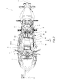
- Fig. 1 is a left side view of an electric motorcycle 1 shown as one example of the saddle type electric vehicle according to the embodiment.
- Fig. 2 is a plan view of the electric motorcycle 1 shown in Fig. 1 .
- the electric motorcycle 1 includes a front wheel 2, a rear wheel 3, and a vehicle body frame 4.
- the front wheel 2 is a steered wheel and a driven wheel, and the rear wheel 3 is a driving wheel.
- the front wheel 2 is rotatably supported by a lower end portion of a front fork 5.
- the front fork 5 extends upward from the lower end portion, pivotally supporting the front wheel 2, while inclining rearward at a caster angle.
- the vehicle body frame 4 includes a head pipe 7, a pair of left and right main frames 8, and a pivot frame 9.
- the head pipe 7 rotatably supports the steering shaft.
- the left and right main frames 8 extend rearward from the head pipe 7, and rear end portions thereof are respectively coupled to left and right side walls of the pivot frame 9.
- the pivot frame 9 supports a front end portion of a swing arm 10, extending in the vehicle lengthwise direction, such that the swing arm 10 is swingable around an axis extending in the vehicle width direction.
- the rear wheel 3 is rotatably supported by a rear end portion of the swing arm 10.
- a seat frame 11 is located above the swing arm 10 and extends rearward from an upper portion of the pivot frame 9.
- a seat 12 for a rider is supported on the seat frame 11.
- a side stand 13 is attached to a lower portion of one of the left and right side walls of the pivot frame 9 so as to be swingable.
- the side stand 13 is set in a horizontal posture so as not to contact the ground.
- the side stand 13 is set in a downward posture to contact the ground together with the front and rear wheels 2 and 3.
- the electric motorcycle 1 stands in an inclined posture.
- the vehicle width center line extending in an upper-lower direction in a rear view extends upward from the vicinity of a ground contact point of the rear wheel 3 so as to be slightly inclined toward one of the left and right sides relative to a vertical direction.
- the electric motorcycle 1 includes a motor unit 15, a power supply unit 20, and an inverter unit 25.
- the motor unit 15 includes: an electric motor 16 as a power source configured to rotate the driving wheel 3; and a motor case 17 accommodating the electric motor 16 and supporting a motor shaft.
- the power source does not include an internal combustion engine.
- the internal combustion engine may be included in addition to the electric motor 16.
- the power supply unit 20 includes: a power supply 21 for the electric motor 16; and a power supply case 22 accommodating the power supply 21.
- the power supply 21 can store DC power.
- the power supply 21 may be exclusively used for the electric motor 16, and the electric motorcycle 1 may include a low-voltage power supply (not shown) for the other electric components in addition to the power supply 21.
- the power supply case 22 is only required to accommodate at least the power supply 21 and does not have to accommodate the low-voltage power supply.
- the inverter unit 25 includes: an inverter 26 capable of converting DC, discharged from the power supply 21, into AC; and an inverter case 27 accommodating the inverter 26.
- the inverter 26 is connected to the power supply 21 via a DC electric wire and is connected to the electric motor 16 via an AC electric wire.
- the electric motor 16 When the AC is supplied from the inverter 26 to the electric motor 16, the electric motor 16 generates driving force, and the motor shaft rotates.
- the driving force of the electric motor 16 i.e., the rotation of the motor shaft
- the driving wheel 3 is transmitted to the driving wheel 3 through a power transmission mechanism 18.
- the power transmission mechanism 18 may include: a reducer configured to decelerate the rotation of the motor shaft; a transmission unit configured to decelerate the decelerated rotation continuously or stepwise at a variable reduction ratio; and a clutch configured to allow or cut off transmission of the rotation from the reducer to the transmission unit.
- the motor shaft (corresponding to an input shaft of the reducer), an input shaft of the transmission unit (corresponding to an output shaft of the reducer), and an output shaft of the transmission unit extend in the vehicle width direction.
- the transmission unit is arranged behind the electric motor 16, and the clutch is provided at one of vehicle width direction end portions (for example, a right-side end portion) of the input shaft of the transmission unit.
- the motor case 17 integrally includes: a transmission unit accommodating section 17b accommodating the transmission unit and provided behind a motor accommodating section 17a accommodating the electric motor 16; and a clutch accommodating section 17c accommodating the clutch and provided adjacent to the transmission unit accommodating section 17b in the vehicle width direction (see Figs. 6 and 8 ).
- the components of the power transmission mechanism 18 accommodated in the motor case 17 also constitute a part of the motor unit 15, and the output shaft of the transmission unit serves as a final output shaft of the motor unit 15.
- the output shaft of the reducer serves as the final output shaft.
- the motor shaft serves as the final output shaft.
- the power transmission mechanism 18 includes a drive mechanism 18d configured to transmit the rotation of the final output shaft of the motor unit 15 to an axle of the driving wheel 3.
- a chain transmission mechanism, a belt transmission mechanism, or an assembly of bevel gears and a drive shaft can be applied as the drive mechanism 18d.
- the final output shaft projects from one of vehicle width direction side walls (for example, a left side wall) of the motor case 17 toward one of vehicle width direction sides (for example, a left side). It is preferable that the final output shaft project toward an opposite side of the clutch accommodating section 17c (see Figs. 6 and 8 ) in the vehicle width direction.
- the clutch has a relatively large diameter among the components accommodated in the motor case 17, the final output shaft can be easily prevented from interfering with the clutch.
- the drive mechanism 18d includes: a driving element fixed onto a projecting end portion of the final output shaft; a driven element fixed onto one of vehicle width direction end portions (for example, a left-side end portion) of the axle of the driving wheel 3; and a transmission element configured to transmit the rotation of the driving element to the driven element.
- Examples of the driving element and the driven element include a sprocket, a pulley, and a bevel gear train, and examples of the transmission element include a chain, a belt, and a drive shaft.
- the drive mechanism 18d is arranged at one of vehicle width direction sides (for example, a left side) of the vehicle width center line.
- the transmission element is provided at the vehicle width outer side of the motor case 17 and extends in the vehicle lengthwise direction.
- the power supply case 22 is physically separated from the motor case 17 and the inverter case 27.
- the motor case 17 and the inverter case 27 are also physically separated from each other, so that these three cases 17, 22, and 27 are separated from one another.
- An accommodating space 4a accommodating the power supply unit 20 is defined by the vehicle body frame 4 so as to be located between the front wheel 2 and the rear wheel 3.
- the accommodating space 4a is formed substantially between the left and right main frames 8.
- the power supply unit 20 overlaps the left and right main frames 8 in a side view and is located at the vehicle width inner side of the left and right main frames 8.
- the motor unit 15 is located lower than the accommodating space 4a and the power supply unit 20.
- the power supply unit 20 may include a downward projecting portion located at a front portion thereof, and the downward projecting portion may be located in front of the motor unit 15 so as to be substantially the same in height as the motor unit 15.
- the motor unit 15 is located lower than the main frames 8 and in front of the pivot frame 9.
- the motor unit 15 is supported by the pivot frame 9 and is also supported by the power supply unit 20.
- the inverter unit 25 is located behind the accommodating space 4a and the power supply unit 20 and behind and above the motor unit 15.
- the inverter unit 25 may be supported by a front end portion of the seat frame 12 and/or an upper portion of the pivot frame 9 and may be interposed between the pivot frame 9 and the seat frame 12 and constitute a part of the vehicle body frame 4.
- the vehicle body frame 4 is configured such that the power supply unit 20 can move in the vehicle width direction to be attached to and detached from the accommodating space 4a.
- a part of the vehicle body frame 4 is detachable from a remaining portion of the vehicle body frame 4.
- the accommodating space 4a is open in the vehicle width direction, and the power supply unit 20 can be inserted into the accommodating space 4a in the vehicle width direction through this open portion and can be taken out from the accommodating space 4a in the vehicle width direction through this open portion.
- a bottom portion of the power supply unit 20 is only required to be lifted up to a bottom portion of the accommodating space 4a.
- the power supply unit 20 is only required to be lifted up to a height which is substantially the same as the height of the mounted state.
- the power supply unit 20 can be inserted into the accommodating space 4a.
- the power supply unit 20 can be attached to and detached from the vehicle body.
- the power supply unit 20 can be attached and detached without being moved to a position higher than the accommodating space 4a.
- the power supply unit 20 moves in the vehicle width direction to get into or get out of the accommodating space 4a. Therefore, even in a case where the handle 6 covers from above a space immediately behind the front fork 5, the space can be utilized as the accommodating space 4a. On this account, both the securing of the caster angle (i.e., a straight traveling property of the motorcycle) and the increase in size of the power supply 21 can be realized.
- the head pipe 7 adopts a box structure, and the stiffness of the vehicle body frame 4 is secured although the vehicle body frame 4 includes a detachable frame.
- the power supply unit 20 moves in the vehicle width direction to get into or get out of the accommodating space 4a, a space under the box structure can also be utilized as the accommodating space 4a. Therefore, while realizing both the structure for opening the accommodating space 4a in the vehicle width direction and the securing of the stiffness of the vehicle body frame 4, the power supply 21 can be increased in size.
- the power supply case 22 includes a main case portion 31 accommodating the power supply 21.
- the main case portion 31 includes a peripheral wall having a closed-circular plane cross section, and the power supply 21 is surrounded by the peripheral wall.
- the power supply case 22 includes a downward projecting portion 32 projecting downward from a front portion of the main case portion 31, and the power supply 21 is also accommodated in the downward projecting portion 32.
- the main case portion 31 includes a rearward projecting portion projecting rearward when viewed from the downward projecting portion 32.
- the power supply 21 includes a plurality of power supply modules 21a electrically connected to one another in series and/or in parallel.
- Each of the power supply modules 21a includes a plurality of battery cells electrically connected to one another in series and/or in parallel. These battery cells are densely arranged, so that the entire power supply module 21a is formed in a rectangular solid shape.
- the plurality of power supply modules 21 a are distributedly accommodated in the main case portion 31 and the downward projecting portion 32.
- the power supply case 22 includes a supporting body 33 supporting from below the power supply 21 accommodated in the main case portion 31.
- the supporting body 33 is provided at a bottom portion of the main case portion 31 along the peripheral wall of the main case portion 31.
- the supporting body 33 is attached to an inner surface of the peripheral wall of the main case portion 31.
- the supporting body 33 projects horizontally from a lower end of the peripheral wall of the main case portion 31 toward an inner side of the peripheral wall and forms a supporting surface facing upward at a bottom portion inside the peripheral wall. This supporting surface supports from below the power supply 21 accommodated in the main case portion 31.
- the main case portion 31 can be reinforced by attaching the supporting body 33.
- the supporting body 33 is only required to provide such a supporting surface for the power supply case 22. Therefore, the supporting body 33 may be attached to the lower end of the peripheral wall of the main case portion 31 from below.
- the supporting body 33 includes an opening which is located at the bottom portion of the main case portion 31 and at a boundary portion between the supporting body 33 and the downward projecting portion 32 and through which a wiring body extends.
- the wiring body electrically connects the power supply modules accommodated in the downward projecting portion 32 to the power supply modules accommodated in the main case portion 31.
- the supporting body 33 seals the inside of the peripheral wall at a rearward portion (i.e., a bottom portion of the above-described rearward projecting portion), located behind the downward projecting portion 32, of the bottom portion of the main case portion 31.
- the supporting body 33 includes engagement holes 34a and 34b with which fastening members 81 for fixing the power supply case 22 engage.
- the engagement holes 34a and 34b face in the vehicle width direction and are open on left and right outer surfaces of the power supply case 22.
- the engagement holes 34a and 34b are formed at portions each of which connects left and right end portions of the supporting body 33 with each other in the vehicle width direction. Therefore, the left and right main frames 8 are coupled to each other in the vehicle width direction via the supporting body 33.
- the supporting body 33 reinforces the vehicle body frame 4 and constitutes a part of the vehicle body frame 4 (i.e., a cross frame coupling the left and right main frames 8 to each other in the vehicle width direction).
- the engagement holes 34a and 34b are separately provided at the front and rear sides.
- the power supply case 22 includes a plurality of first mount portions 35a and 35b for coupling with the motor unit 15.
- the power supply case 22 is formed to have a shape obtained by turning an L shape to the right at 90 degrees.
- the motor unit 15 is arranged in a space secured at a rear lower side of the power supply case 22 having such a shape.
- the motor unit 15 is arranged at a position which is under the main case portion 31, is substantially the same as the position of the main case portion 31 in the vehicle lengthwise direction and the vehicle width direction, is behind the downward projecting portion 32, and is substantially the same as the position of the downward projecting portion 31 in the upper-lower direction and the vehicle width direction.
- the first mount portions 35a and 35b are arranged at a bottom portion of the main case portion 31 (especially, the above-described rearward projecting portion) and attached to the supporting body 33.
- the supporting body 33 is provided with two front first mount portions 35a respectively located at left and right sides of a rear end portion of the boundary portion or a front end portion of the rearward portion (i.e., a bottom front end portion of the above-described rearward projecting portion).
- the supporting body 33 is also provided with two rear first mount portions 35b respectively located at the left and right sides of the rear end portion of the supporting body 33.
- the supporting body 33 is utilized for supporting the power supply 21, reinforcing the power supply case 22, sealing the power supply case 22, fixing the power supply unit 20 to the vehicle body frame 4, reinforcing the vehicle body frame 4, supporting the motor unit 15, and the like.
- the supporting body 33 may be made of a metal, such as an aluminum alloy. With this, the supporting body 33 obtains high stiffness, so that the stiffness for supporting the power supply 21 and the motor unit 15 and the strength of the reinforcement of the power supply case 22 and the vehicle body frame 4 improve.
- the peripheral wall of the main case portion 31 may be made of the same type of metal as the supporting body 33, and the supporting body 33 may be welded to the peripheral wall of the main case portion 31. With this, the sealing property of the power supply case 22 improves.
- the structure of the supporting body 33 is not especially limited as long as the above configurations and functions are realized.
- Fig. 3 is a perspective view showing one example of the supporting body 33 shown in Fig. 1 .
- the supporting body 33 includes: a frame member 33a configured such that a plurality of square pipes are assembled in a frame shape so as to correspond to a plane cross-sectional shape of the main case portion 31 (see Fig. 1 ); and a plate member 33b configured to seal an inside of a rear portion of the frame member 33a.
- the plate member 33b seals the inside of the peripheral wall to prevent the muddy water and the like from getting into the power supply case 22 (see Fig. 1 ).
- the frame member 33a includes: left and right pipes 31p and 31q respectively provided along left and right side walls of the peripheral wall; a front pipe 33r coupling front end portions of the left and right pipes 33p and 33q to each other and provided along a front side wall of the peripheral wall; and a rear pipe 33s coupling rear end portions of the left and right pipes 33p and 33q to each other and provided along a rear side wall of the peripheral wall.
- Upper surfaces of the pipes 33p to 33s form the above-described supporting surface, and the supporting surface is formed in a frame shape along the inner surface of the peripheral wall in a plan view.
- the supporting body 33 may include a coupling pipe 33t coupling vehicle lengthwise direction middle portions of the left and right pipes 33p and 33q to each other in the vehicle width direction. With this, the strength of the supporting body 33 improves.
- the coupling pipe 33t can be used as a component to which an upper rear edge of the downward projecting portion 32 (see Fig. 1 ) is attached and to which a front edge of the plate member 33b is joined.
- the downward projecting portion 32 is easily, liquid-tightly attached to the supporting body 33, and the plate member 33b is easily, liquid-tightly attached to the frame member 33a.
- the engagement holes 34a are respectively provided at left and right end portions of the coupling pipe 33t, and the engagement holes 34a and 34b are respectively provided at left and right end portions of the rear pipe 33s.
- the supporting body 33 can reinforce the vehicle body frame 4 as described above.
- the front first mount portion 35a is attached to the coupling pipe 33t, and the rear first mount portions 35b are respectively attached to left and right portions of the rear pipe 33s.
- the power supply case 22 includes an electric component accommodating portion 37 accommodating electric components, and the electric component accommodating portion 37 is located above the main case portion 31.
- the electric components include: a relay group configured to open or close wires connecting the power supply 21 to the inverter 26, the low-voltage power supply, and a charging connector 38; a DC/DC converter interposed on the wire connecting the power supply 21 to the low-voltage power supply; a service plug configured to open or close the wire connecting the power supply 21; a sensor group configured to detect an electric leakage, a current value, and the like of the power supply 21; and a power supply monitoring unit configured to monitor a state of the power supply 21.
- Electric circuits around the power supply 21 can be assembled in accordance with a flow different from a flow of assembling the vehicle body. Thus, the production efficiency of the vehicle improves.
- the power supply unit 20 includes the charging connector 38 provided above the main case portion 31.
- the charging connector 38 constitutes the power supply unit 20. Further, the wire connecting the charging connector 38 to the power supply 21 and a charge monitoring unit constitute the power supply unit 20. Therefore, even in a case where the power supply unit 20 is detached from the vehicle body, maintenance, such as charge inspection of the power supply 21, can be performed.
- the power supply unit 20 is practically allowed to be stored and transported separately from the vehicle body.
- the power supply unit 20 since the power supply unit 20 is simply mounted to the vehicle body, workload at the time of assembly is small. Further, the power supply unit 20 is practically allowed to be sold or rented independently from the vehicle body. Even in this case, according to the present embodiment, a completed vehicle can be provided quickly.
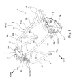
- Fig. 4 is a perspective view of the vehicle body frame 4 shown in Figs. 1 and 2 .
- the vehicle body frame 4 (especially, the left and right main frames 8) is located at the vehicle width outer side of the power supply unit 20 in the mounted state.
- the vehicle body frame 4 includes a detachable frame portion 50 defining the accommodating space 4a.
- the detachable frame portion 50 is detachably coupled to the remaining portion of the vehicle body frame 4. By detaching the detachable frame portion 50 from the remaining portion, the accommodating space 4a is open in the vehicle width direction.
- the detachable frame portion 50 is detachably fastened to the remaining portion by using fastening members 82 (see Fig. 1 ), inserted into and disengaged from the remaining portion in the vehicle width direction, in a state where front and rear end portions of the detachable frame portion 50 are brought into contact with the remaining portion from the vehicle width outer side.
- the detachable frame portion 50 includes a plurality of through holes 52 through which the fastening members 82 are respectively inserted.
- the remaining portion includes a plurality of engagement holes 53 with which the fastening members 82 inserted through the through holes 52 respectively engage.
- the fastening members 82 are typically bolts, and the engagement holes 53 may be internal threads.
- the engagement holes 53 face in the vehicle width direction. Therefore, the through holes 52 also face in the vehicle width direction in a state where the detachable frame portion 50 is attached to the remaining portion.
- the fastening members 82 are also inserted into and disengaged from the remaining portion in the vehicle width direction.
- the detachable frame portion 50 may constitute both of the main frames 8 or may constitute one of the main frames 8. Since the detachable frame portion 50 constitutes at least one of the main frames 8, the head pipe 7 and the pivot frame 9 constitute the above-described remaining portion. In a case where the detachable frame portion 50 constitutes only one of the main frames 8, the main frame 8 (hereinafter referred to as a "fixed main frame 51" for convenience of explanation) which is not constituted by the detachable frame portion 50 and is integrated with the head pipe 7 and the pivot frame 9 is also included in the remaining portion.
- the accommodating space 4a is open in the vehicle width direction and the upper direction. This open portion spreads from the head pipe 7 to the pivot frame 9 in a side view. By using this large open portion, the large power supply unit 20 can be easily accommodated in the accommodating space 4a without being lifted up to a high position (also see Fig. 6 ).
- the detachable frame portion 50 constitutes only one of the main frames 8 (for example, the left main frame).
- the other main frame i.e., the fixed main frame 51
- the one main frame i.e., the detachable frame portion 50. With this, the stiffness of the entire vehicle body frame 4 becomes high while one of the main frames 8 is configured to be detachable.
- the other main frame may include a connecting frame 51a which branches from a part of a portion (corresponding to a below-described main portion 66) extending from the head pipe 7 toward the pivot frame 9 and is connected to the seat frame 11.
- the other main frame may be larger in thickness and/or outer shape than the one main frame.
- the head pipe 7 as the remaining portion includes a structure by which the front end portion of the detachable frame portion 50 is detachably fastened to the head pipe 7.
- the pivot frame 9 as the remaining portion includes a structure by which the rear end portion of the detachable frame portion 50 is detachably fastened to the head pipe 7.
- a rear end portion of the fixed main frame 51 is connected to the side wall (for example, the right side wall) provided at a side where the fixed main frame 51 is provided, out of the left and right side walls of the pivot frame 9.
- the fixed main frame 51 may be welded to this side wall or may be formed integrally with this side wall.
- the rear end portion of the detachable frame portion 50 is detachably coupled to the side wall (for example, the left side wall) provided at a side where the detachable frame portion 50 is provided.
- a connection portion 54 is provided at a vehicle width outer side surface of this side wall.
- the rear end portion of the detachable frame portion 50 is brought into contact with the connection portion 54 from the vehicle width outer side and is detachably coupled to the connection portion 54 by using the fastening members 82.
- a part of the above-described engagement holes 53 i.e., one or more engagement holes 53
- One or more through holes 52 are formed at the rear end portion of the detachable frame portion 50 such that the number of through holes 52 and the positions of the through holes 52 respectively correspond to the number of engagement holes 53 and the positions of the engagement holes 53.
- the head pipe 7 includes a cylindrical pipe portion 55 and a box-shaped joint portion 56 provided at a rear portion of the pipe portion 55.
- the above-described steering shaft (not shown) is inserted through and rotatably supported by the pipe portion 55.
- the main frames 8 are respectively coupled to left and right rear portions of the joint portion 56.
- the fixed main frame 51 is integrally coupled to one of the left and right rear portions of the joint portion 56 (for example, the right rear portion) by using a joining method, such as welding.
- the detachable frame portion 50 is detachably coupled to the other of the left and right rear portions of the joint portion 56 (for example, the left rear portion) by using the fastening members 82.
- the joint portion 56 includes a joint plate 57 welded to a front end portion of the fixed main frame 51.
- the joint plate 57 is provided at a portion (for example, the right rear portion) to which the fixed main frame 51 is coupled, out of the left and right rear portions of the joint portion 56.
- a surface of the joint plate 57 faces substantially rearward.
- the front end portion of the fixed main frame 51 is connected to this surface of the joint plate 57 without using the fastening member.
- the fixed main frame 51 may be welded to the joint plate 57 or may be formed integrally with the joint portion 56.
- the joint portion 56 includes a connection plate 58.
- connection plate 58 is provided at a portion (for example, the left rear portion) to which the detachable frame portion 50 is coupled, out of the left and right rear portions of the joint portion 56.
- a surface of the connection plate 58 faces in the vehicle width outer direction.
- the front end portion of the detachable frame portion 50 is brought into contact with the surface of the connection plate 58 from the vehicle width outer side and is detachably coupled to the connection plate 58 by using the fastening members 82.
- a part of the above-described engagement holes 53 i.e., one or more engagement holes 53
- One or more through holes 52 are formed at the front end portion of the detachable frame portion 50 such that the number of through holes 52 and the positions of the through holes 52 respectively correspond to the number of engagement holes 53 and the positions of the engagement holes 53.
- the rear end portion of the detachable frame portion 50 is brought into contact with the surface of the connection portion 54 from the vehicle width outer side, and the front end portion of the detachable frame portion 50 is brought into contact with the surface of the connection plate 58 from the vehicle width outer side.
- the through holes 52 are matched with the corresponding engagement holes 53.
- the fastening members 82 are inserted into the corresponding holes 52 and 53 from the vehicle width outer side of the detachable frame portion 50 toward the vehicle width inner side to engage with the engagement holes 53.
- the detachable frame portion 50 constitutes one of the main frames 8, forms a pair with the fixed main frame 51, and extends from the head pipe 7 to the pivot frame 9.
- a procedure opposite to the above is performed.
- the work of attaching and detaching the detachable frame portion 50 accompanies the work of attaching and detaching the power supply unit 20 to and from the vehicle body. Both of these works are performed at one side of the accommodating space 4a in the vehicle width direction. Therefore, the working property of the work of attaching and detaching the power supply unit 20 improves (see Fig. 6 ).
- the connection portion 54 may be provided with a plurality of (for example, two) engagement holes 53.
- the plurality of engagement holes 53 may be arranged on the connection portion 54 so as to be separated from one another in the upper-lower direction and the vehicle lengthwise direction. Further, the plurality of engagement holes 53 may be arranged so as to be separated from one another in the upper-lower direction or the vehicle lengthwise direction (the plurality of engagement holes 53 may be arranged so as to be the same in positions as one another in one of the vehicle lengthwise direction and the upper-lower direction). The same is true for the engagement holes 53 formed on the connection plate 58.
- the joint portion 56 is formed in a box shape. Because of such a strong box structure of the joint portion 56, even in a case where one of the main frames 8 is detachable from the remaining portion of the vehicle body frame 4, the joint portion 56 can receive the load. Thus, the stiffness of the entire vehicle body frame 4 in an assembled state can be secured.
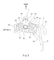
- Fig. 5 is a plan view showing components around the head pipe 7 shown in Fig. 4 .
- the joint portion 56 will be explained more specifically.
- the joint portion 56 includes a pair of left projecting portions 61 extending rearward from the head pipe 7 to the left side and a pair of right projecting portions 61 extending rearward from the head pipe 7 to the right side.
- the left projecting portions 61 are arranged in the upper-lower direction, and the right projecting portions 61 are arranged in the upper-lower direction.
- the above-described joint plate 57 couples rear end portions of the projecting portions 61 located at one of the left and right sides (for example, the right side) and arranged in the upper-lower direction.
- connection plate 58 couples rear end portions of the projecting portions 61 located at the other side (for example, the left side) and arranged in the upper-lower direction.
- the projecting portions 61 arranged at the upper side in the left-right direction are coupled to each other by a ceiling plate 64, and the projecting portions 61 arranged at the lower side in the left-right direction are coupled to each other by a bottom plate 63.
- the ceiling plate 64 and the bottom plate 63 are provided in a gusset shape which couples the left and right projecting portions 61 and the pipe portion 55.
- the projecting portions 61 arranged in the upper-lower direction are coupled to each other by an inclined portion 65.
- the inclined portion 65 is formed in a brace shape extending from the rear end portion of one of the projecting portions (for example, the projecting portion at the upper side) 61 to a front end portion of the other projecting portion (for example, the projecting portion at the lower side) 61. Front end portions of the inclined portions 65 at the left and right sides are respectively coupled to the projecting portions 61 which are located at one of the upper or lower sides.
- each of the main frames 8 includes the main portion 66 which extends rearward from the head pipe 7 and inclines slightly downward to be coupled to the pivot frame 9.
- each of the main frames 8 includes a down portion 67 which is located under the main portion 66, extends downward from the head pipe 7, and inclines slightly rearward.
- each of the main frames 8 include a coupling portion 69 extending downward from a part of the main portion 66 to be connected to a lower end portion of the down portion 67.
- a front end portion of the main portion 66 is spaced apart from a front end portion of the down portion 67 in the upper-lower direction.
- the main frame 8 (especially, the main frame constituted by the detachable frame portion 30) includes a connecting plate 68 connecting these front end portions.
- the detachable frame portion 50 may be coupled to the head pipe 7 in a state where an inner surface of the connecting plate 68 surface-contacts a surface of the connection plate 58. With this, the load acting on the detachable frame portion 50 can be received by these contacting surfaces. Thus, the stiffness of the entire vehicle body frame 4 improves. Similarly, an inner surface of the rear end portion of the detachable frame portion 50 may surface-contact a surface of the connection portion 54.
- Each of the main frames 8 (the detachable frame portion 50 and the fixed main frame 51) is coupled to the joint portion 56 such that the main portion 66 extends rearward and downward continuously in the vehicle lengthwise direction from a rear end of the projecting portion 61 at the upper side.
- each of the main frames 8 is coupled to the joint portion 56 such that the down portion 67 extends downward and rearward continuously in the vehicle lengthwise direction from a rear end of the projecting portion 61 at the lower side. Therefore, a forward load from the main frame 8 smoothly acts on the joint portion 56, and the load acting on the joint portion 56 smoothly acts on the ceiling plate 64, the bottom plate 63, and the pipe portion 55 via the projecting portion 61.
- Each of the main frames 8 includes bosses 70a and 70b through which the fastening members 81 (see Fig. 1 ) for coupling the power supply unit 20 with the main frame 8 are inserted.
- the engagement holes 34a and 34b (see Fig. 3 ) which engage with the fastening members 81 are provided at the supporting body 33 so as to be respectively located at the front and rear sides (see Fig. 3 ).
- the engagement holes 34a are respectively formed at the left and right end portions of the coupling pipe 33t (see Fig. 3 ), and the engagement holes 34b are respectively formed at the left and right end portions of the rear pipe 33s (see Fig. 3 ).
- the bosses 70a and 70b form a pair in the forward and rearward direction so as to correspond to the engagement holes 34a and 34b.
- the boss 70a at the front side is provided at the lower end portion of the down portion 67
- the boss 70b at the rear side is provided at a rear end portion of the main portion 66 and in front of a part of the main portion 66 which is coupled to the pivot frame 9.
- a triangle is formed by: the coupling portion 69; a portion of the main portion 66 which extends rearward from a portion from which the coupling portion 69 branches; and a portion of the left or right pipe 33p or 33q of the supporting body 33 which extends between the coupling pipe 33t and the rear pipe 33s in the vehicle lengthwise direction.
- the main frames 8 and the supporting body 33 constitute a highly-stiff frame structure in cooperation with one another, and this significantly contributes to the improvement of the stiffness of the entire vehicle body frame 4.
- Fig. 6 is a perspective view showing a state before the power supply unit 20 is mounted to the vehicle body of the electric motorcycle 1 shown in Fig. 1 .
- Fig. 7 is a front view showing the same state as Fig. 6 .
- the procedure of assembling the power supply unit 20 to the vehicle body will be explained in order.
- the vehicle body to which the power supply unit 20 is to be mounted is prepared.
- the vehicle body herein is configured by mounting the front wheel 2, the swing arm 10, the rear wheel 3, the motor unit 15, the power transmission mechanism 18, and the inverter unit 25 to the remaining portion of the vehicle body frame 4.
- the vehicle body herein does not include the detachable frame portion 50.
- a cowl member for example, a left side cowl arranged at the vehicle width outer side of the detachable frame portion 50 is not included in the vehicle body and is detached.
- the motor unit 15 is cantilevered by the pivot frame 9 so as to project forward from the pivot frame 9.
- the pivot frame 9 includes the left and right side walls.
- a panel 71 having a substantially rectangular shape is arranged between the left and right side walls of the pivot frame 9 such that surfaces thereof respectively face forward and rearward.
- the panel 71 is fixed to inner surfaces of the left and right side walls of the pivot frame 9.
- the motor unit 15 is fixed to the panel 71 by a plurality of bolts inserted from behind and is cantilevered by the pivot frame 9 via the panel 71.
- Such a support structure is adopted, so that even in a case where the motor unit 15 is not coupled to the power supply unit 20, the motor unit 15 can be maintained to be firmly mounted to the remaining portion of the vehicle body frame 4.
- the accommodating space 4a is open at one vehicle width direction side (for example, the left side) to which the detachable frame portion 50 is attached.
- the accommodating space 4a is formed between the front wheel 2 and the rear wheel 3.
- the accommodating space 4a is formed behind the head pipe 7 and in front of the inverter unit 25.
- the accommodating space 4a is formed in front of at least one of the seat 12, the seat frame 12, and the pivot bracket 9.
- the accommodating space 4a is largely formed above the motor unit 15. In consideration of the ease of the attaching and detaching works, it is preferable that the accommodating space 4a be provided as low as possible.
- a lower end of the accommodating space 4a is located above a road surface and under upper ends of the front and rear wheels 2 and 3.
- the lower end of the accommodating space 4a may be located under the axles of the front and rear wheels 2 and 3.
- the accommodating space 4a is formed at the vehicle width inner side of the fixed main frame 51.
- the motor unit 15 is one of components surrounding the accommodating space 4a.
- the electric motor 16 is arranged at a position except for the accommodating space 4a and a region extended from the accommodating space 4a in the vehicle width direction, that is, a position which is separated from the accommodating space 4a in the upper and lower directions and the forward direction and/or the rearward direction and does not overlap the accommodating space 4a in a side view.
- a part of the power transmission mechanism 18 constitutes the motor unit 15 together with the electric motor 16, and another part of the power transmission mechanism 18 is located at the vehicle width outer side of the motor unit 15 and extends in the vehicle lengthwise direction.
- the arrangement relation between the power transmission mechanism 18 and the accommodating space 4a is similar to the above-described arrangement relation between the electric motor 16 and the accommodating space 4a.
- the electric motor 16 and the power transmission mechanism 18 do not interfere with the power supply unit 20. Conversely, even in a case where the electric motor 16 and the power transmission mechanism 18 are mounted to the remaining portion of the vehicle body frame 4, the power supply unit 20 can be easily accommodated in the accommodating space 4a.
- a mounting device 90 stands by at the vehicle width outer side of vehicle body and a side where the accommodating space 4a is open.
- the mounting device 90 includes: a base 91; a pair of posts 92 standing from one side edge of the base 91; and a pair of forks 93 respectively, horizontally extending from the posts 92.
- the mounting device 90 is placed next to the vehicle body such that: the posts 92 are spaced apart from each other in the vehicle lengthwise direction; the one side edge of the base 91 is arranged distant from the accommodating space 4a; and the forks 93 are spaced apart from each other in the vehicle lengthwise direction as with the posts 92 and extend from the posts 92 to the vehicle width inner side.
- the fork 93 at the front side is inserted through a front holder 36a, fixed to an outer front surface of the power supply case 22, from the vehicle width outer side to the vehicle width inner side.
- the fork 93 at the rear side is inserted through a rear holder 36b, fixed to an outer rear surface of the power supply case 22, from the vehicle width outer side to the vehicle width inner side.
- the power supply unit 20 is supported by the mounting device 90 so as to float from the ground.
- the power supply unit 20 is accommodated in the accommodating space 4a. Therefore, the power supply unit 20 is only required to be lifted up to a height which is the same as the height of the mounted state.
- the power supply unit 20 is moved to the vehicle width inner side.
- the base 91 may be moved to the vehicle width inner side.
- the base 91 is constituted by a cart which can travel in at least a direction in which the forks 93 extend, and the height of the base 91 is made shorter than a distance from the ground to a lower end of the motor unit 15. Since the lower end of the accommodating space 4a is located above the road surface, the base 91 can be inserted under the motor unit 15, and a traveling direction front end portion of the base 91 can be inserted to a position under the accommodating space 4a. Thus, the power supply unit 20 can be smoothly accommodated in the accommodating space 4a.
- the side stand 13 is in the horizontal posture, so that even in a case where the side where the accommodating space 4a is open and the side where the side stand 13 is arranged are the same as each other in the vehicle width direction when viewed from the vehicle width center line, the side stand 13 does not interfere with the movement of the base 91.
- the posts 92 may be moved to the vehicle width inner side relative to the base 91.
- sliders which slide in the direction in which the forks 93 extend are provided on the base 91, and the posts 92 are attached on the sliders.
- the forks 93 may extend in the vehicle width direction. In this case, the forks 93 are configured to be extendable.
- the power supply unit 20 When the power supply unit 20 is moved to the vehicle width inner side, as described above, the power supply unit 20 is inserted into the accommodating space 4a through the open portion at the vehicle width outer side.
- Fig. 8 is a diagram showing the arrangement of the rear first mount portions 35b and the rear second mount portions 72b.
- the side where the clutch accommodating section 17c is arranged when viewed from the vehicle width center line, the side where the clutch accommodating section 17c is arranged is opposite in the vehicle width direction to the side where the accommodating space 4a is open.
- the clutch accommodating section 17c may be formed to project in a radial direction when viewed from a remaining portion of the motor case 17 (for example, the motor accommodating section 17a and the transmission unit accommodating section 17b).
- the side (for example, the left side) where the accommodating space 4a is open is opposite to the side (for example, the right side) where the clutch accommodating section 17c is arranged. Therefore, the power supply unit 20 can be accommodated in the accommodating space 4a without getting over the clutch accommodating section 17c. Thus, a space above the motor accommodating section 17a and the transmission unit accommodating section 17b can be easily utilized as the accommodating space 4a.
- a plurality of (for example, four) second mount portions 72a and 72b corresponding to the first mount portions 35a and 35b are formed on an upper surface of the motor case 17.
- the four first mount portions 35a and 35b are brought into contact with the corresponding second mount portions 72a and 72b in the vehicle width direction.
- the first mount portions 35a and 35b are brought into contact with the corresponding second mount portions 72a and 72b from the side (for example, the left side) where the accommodating space 4a is open in the vehicle width direction when viewed from the second mount portions 72a and 72b.
- the front first mount portion 35a located at the side (for example, the right side) where the fixed main frame 51 is provided needs to get over the front second mount portion 72a located at the side (for example, the left side) where the accommodating space 4a is open. Then, only by moving the power supply unit 20 horizontally in the vehicle width direction, the two front first mount portions 35a are properly brought into contact with the front second mount portions 72a. The same is true for the rear first mount portions 35b and the rear second mount portions 72b, and the same is true for the process of taking out the power supply unit 20 from the accommodating space 4a. Therefore, when supporting the motor unit 15 by the power supply unit 20, this support structure is prevented from hindering the work of attaching and detaching the power supply unit 20. In addition, the necessity of securing a space above the motor unit 15 just for allowing the movements of the first mount portions 35a and 35b decreases.
- the power supply unit 20 is properly accommodated in the accommodating space 4a. Then, the fastening members 83 are inserted into the mount portions 34a, 34b, 72a, and 72b from the vehicle width outer side. Thus, the motor unit 15 is coupled to the power supply unit 20.
- the engagement holes 34a and 34b formed at the power supply unit 20, specifically the front engagement hole 34a and the rear engagement hole 34b which are provided at a side opposite to the side where the accommodating space 4a is open in the vehicle width direction match with the front boss 70a and rear boss 70b of the fixed main frame 51 in the vehicle width direction.
- the fastening members 81 are inserted into the bosses 70a and 70b and the corresponding engagement holes 34a and 34b from the vehicle width outer side to the vehicle width inner side and engage with the engagement holes 34a and 34b.
- the fixed main frame is detachably coupled to the power supply unit 20 (specifically the supporting body 33, more specifically the coupling pipe 33t and rear pipe 33s of the supporting body 33).
- the power supply unit 20 is properly accommodated in the accommodating space 4a, is supported by the remaining portion of the vehicle body frame 4, and supports the motor unit 15 together with the vehicle body frame 4.
- the detachable frame portion 50 may be fixed to the power supply unit 20 before the power supply unit 20 is lifted up by the mounting device 90.
- the detachable frame portion 50 is detachably coupled to the remaining portion of the vehicle body frame 4.
- the inner surface of the connecting plate 68 provided at the front end portion of the detachable frame portion 50 is brought into surface-contact with the connection plate 58 of the head pipe 7 from the vehicle width outer side, and the inner surface of the rear end portion of the detachable frame portion 50 is brought into surface-contact with the connection portion 54 of the pivot frame 9 from the vehicle width outer side.
- the through holes 52 formed on the connecting plate 68 are matched in the vehicle width direction with the engagement holes 53 which are open on the connection plate 58, and the through holes 52 formed on the rear end portion are matched in the vehicle width direction with the engagement holes 53 which are open on the surface of the connection portion 54.
- the fastening members 82 are inserted into the through holes 52 and the engagement holes 53 and engage with the engagement holes 53.
- the detachable frame portion 50 is detachably coupled to the head pipe 7 and the pivot frame 9 which serve as the remaining portion of the vehicle body frame 4.
- the accommodating space 4a is closed by the fixed main frame 51 and the detachable frame portion 50 in the vehicle width direction.
- wire connecting works required among the electric components provided at the power supply unit 20 and the electric components provided at the vehicle body is performed.
- Connectors for these works are arranged on an outer surface of the power supply case 22.
- the wire connecting works are completed.
- the inverter 26 and the low-voltage power supply are arranged outside the power supply unit 20, and by attaching or detaching the connectors, the wire connecting works between the power supply 21 and the inverter 26 and between the power supply 21 and the low-voltage power supply are performed.
- the power supply unit 20 can be easily shifted to an attachable and detachable state.
- the vehicle body frame 4 is configured such that the accommodating space 4a accommodating the power supply unit 20 can be open in the vehicle width direction. Therefore, when mounting the power supply unit 20 to the vehicle body, the power supply unit 20 is only required to be lifted up to a height which is substantially the same as the height of the mounted state. Then, the power supply unit 20 is moved in the vehicle width direction through the open portion of the accommodating space 4a. Thus, the power supply unit 20 can be accommodated in the accommodating space 4a through the open portion of the accommodating space 4a. With this, the work of mounting the power supply unit 20 to the vehicle body can be easily performed.
- the power supply 21 accommodated in the power supply case 22 includes a power supply portion positioned so as not to hinder the insertion of the forks 93 into the power supply case 22 and projecting to a lower side of the supporting surface. With this, the capacity of the power supply 21 can be made large.
- the power supply portion projecting downward from the supporting surface is formed at a position spaced apart in the forward and rearward direction from the positions to which the forks 93 are inserted, specifically, at a front portion of the power supply case 21.
- the power supply case 21 includes the downward projecting portion 32 accommodating the power supply portion.
- the power supply unit 20 of the present embodiment includes the downward projecting portion 32 projecting downward from the front portion of the main case portion 31, and a lower end of the downward projecting portion 32 is substantially the same in height as the lower end of the motor unit 15.
- the entire power supply unit 20 including the portions arranged at low positions in a mount state needs to be lifted up to a position higher than the main frame 8. Therefore, the mounting work becomes extremely complex.
- the portions arranged at the low positions in the mount state can be accommodated in the accommodating space 4a only by lifting up the potions to those positions.
- the main frame constituted by the detachable frame portion 50 may be arranged at a side opposite in the vehicle width direction to a side where the power transmission mechanism 18 (especially, the drive mechanism 18d) is arranged.
- the power transmission mechanism 18 especially, the drive mechanism 18d
- the load from the power transmission mechanism 18 acts on the vehicle body frame 4 through the axle of the rear wheel 3 and the swing arm 10. This load becomes high at one vehicle width direction side, where the drive mechanism 18d is arranged, of the vehicle body frame 4.
- the fixed main frame 51 can receive the load from the power transmission mechanism 18, and the load from the power transmission mechanism 18 hardly acts on the detachable frame portion 50. Therefore, the required stiffness of the detachable frame portion 50 can be reduced, and the structure for attaching the detachable frame portion 50 to the remaining portion can be simplified.
- the stiffness of the fixed main frame 51 is made higher than that of the detachable frame portion 50 as in the above embodiment, the stiffness can be suitably improved at the side where the load from the power transmission mechanism tends to be received.
- the vehicle body frame 4 suitable for an acting load distribution can be provided.
- the power supply 21 included in the power supply unit 20 is only required to be able to supply electric power to the electric motor 16.
- Examples of the power supply 21 include: a battery, such as a lithium ion battery, utilizing a chemical reaction; a battery using a capacitor electrically storing electric charge; a battery (such as a fuel cell) including a power generating unit, secondary battery chargeable by an external power supply or an internal power generator; and a primary battery replaced with a new one every time the amount of charge decreases.
- the opening through which the power supply unit 20 is attached and detached is formed by detaching a part of the vehicle body frame 4 from the remaining portion of the vehicle body frame 4.
- the vehicle body frame 4 does not have to include such a detachable frame.
- An opening through which the power supply unit 20 can pass in the vehicle width direction may be formed at the vehicle body frame 4 in advance.
- the saddle type electric vehicle is not limited to the electric motorcycle which travels by an output equal to an output of a motorcycle driven by an internal combustion engine and may be an electric bicycle. Further, the saddle type electric vehicle may be a buggy car, such as an ATV, including three or more wheels. Furthermore, the saddle type electric vehicle may be a vehicle on which a rider rides in such a riding posture that the legs are put together in front of the seat, not in such a riding posture that the rider completely sits astride the seat, such as a scooter.
- the vehicle body may be provided with a center stand by which the vehicle can stand while maintaining a horizontal state of the axle. Since the holders 36a and 36b extend horizontally, a device which stands the vehicle body for inserting the forks 93 becomes unnecessary. On the other hand, the holders 36a and 36b may be attached such that the openings of the holders 36a and 36b become horizontal when the vehicle body stands in the inclined state by the side stand 13.
- the inverter case 27 is physically separated from the power supply case 22.
- the inverter 26 and the low-voltage power supply may be accommodated in the power supply unit 20.
- the present invention has the above-described effects and is suitably applicable to an electric vehicle which is a saddle type vehicle and travels by using an electric motor as a power source.
Landscapes
- Engineering & Computer Science (AREA)
- Mechanical Engineering (AREA)
- Transportation (AREA)
- Power Engineering (AREA)
- Life Sciences & Earth Sciences (AREA)
- Sustainable Development (AREA)
- Sustainable Energy (AREA)
- Chemical & Material Sciences (AREA)
- Chemical Kinetics & Catalysis (AREA)
- General Chemical & Material Sciences (AREA)
- Electrochemistry (AREA)
- Combustion & Propulsion (AREA)
- Manufacturing & Machinery (AREA)
- Aviation & Aerospace Engineering (AREA)
- General Physics & Mathematics (AREA)
- Physics & Mathematics (AREA)
- Electric Propulsion And Braking For Vehicles (AREA)
- Automatic Cycles, And Cycles In General (AREA)
- Arrangement Or Mounting Of Propulsion Units For Vehicles (AREA)
- Secondary Cells (AREA)
- Battery Mounting, Suspending (AREA)
- Automatic Assembly (AREA)
- Charge And Discharge Circuits For Batteries Or The Like (AREA)
Abstract
Description
- The present invention relates to a saddle type electric vehicle including an accommodating space located between front and rear wheels and accommodating a power supply unit.
- To secure a cruising distance, a saddle type electric vehicle needs to be equipped with a battery box accommodating a large-capacity battery. In PTL 1, a large battery box is supported by a main frame from below and accommodated in a vehicle body cover attached to a vehicle body frame.
- PTL 1: Japanese Laid-Open Patent Application Publication No.
2010-100124 - To accommodate the battery box in the vehicle body cover as above, the battery box needs to be lifted up once to a position higher than the vehicle body frame. Therefore, a work of mounting the battery box to the vehicle body frame is complex, and an apparatus for lifting up the battery box to a high position is large.
- An object of the present invention is to provide a saddle type electric vehicle configured such that a power supply can be easily mounted to a vehicle body.
- A saddle type electric vehicle according to the present invention is a saddle type electric vehicle which travels by using an electric motor as a power source, the saddle type electric vehicle comprising: a power supply unit including a power supply for the electric motor; and a vehicle body frame defining an accommodating space located between front and rear wheels and accommodating the power supply unit, wherein the vehicle body frame is configured such that the power supply unit is attachable to and detachable from the accommodating space in a vehicle width direction.
- According to the above configuration, the vehicle body frame is detached, and the power supply unit is lifted up to a height which is substantially the same as the height of the mount state. With this, by just moving the power supply unit in the vehicle width direction, the power supply unit can be accommodated in the accommodating space. As above, it becomes unnecessary to lift up the power supply unit to a high position, and the power supply unit can be easily mounted to the vehicle body.
- The saddle type electric vehicle may be configured such that: the vehicle body frame includes a detachable frame portion located at a vehicle width direction outer side of the power supply unit and defining the accommodating space; the detachable frame portion is detachably coupled to a remaining portion of the vehicle body frame; and by detaching the detachable frame portion from the remaining portion, the accommodating space is open in the vehicle width direction.
- According to the above configuration, by detaching the detachable frame portion, the power supply unit can be moved in the vehicle width direction to be attached to or detached from the vehicle body. By attaching the detachable frame portion, the power supply unit accommodated in the accommodating space can be protected in the vehicle width direction.
- The saddle type electric vehicle may be configured such that the detachable frame portion is detachably fastened to the remaining portion by fastening members inserted into and disengaged from the remaining portion in the vehicle width direction in a state where front and rear end portions of the detachable frame portion contact the remaining portion from the vehicle width direction outer side.
- According to the above configuration, since the load can be received by the contact portions, the stiffness of the entire vehicle body frame improves.
- The saddle type electric vehicle may be configured such that: the vehicle body frame includes a head pipe and a pair of left and right main frames extending rearward from the head pipe; and the detachable frame portion constitutes at least one of the main frames.
- According to the above configuration, since only one of the main frames is detachable, the stiffness of the vehicle body frame can be increased.
- The saddle type electric vehicle may be configured such that: the head pipe includes a cylindrical pipe portion and a box-shaped joint portion provided at a rear portion of the pipe portion; and the main frames are respectively coupled to left and right rear portions of the joint portion.
- According to the above configuration, since the joint portion is formed in a box shape, the stiffness of the joint portion can be increased. Therefore, even in a case where a part of the vehicle body frame is detachable, the stiffness of the entire vehicle body frame can be secured.
- The saddle type electric vehicle may further include: a power transmission mechanism configured to transmit driving force, generated by the electric motor, to a driving wheel, wherein: the power transmission mechanism may be provided at one of vehicle width direction sides of a vehicle width center line; the detachable frame portion may constitute one of the main frames; and the one main frame may be provided at the other vehicle width direction side opposite to the one vehicle width direction side where the power transmission mechanism is provided.
- According to the above configuration, in a case where the vehicle body frame includes a pair of main frames, the load acting on the main frame located at the vehicle width direction side where the power transmission mechanism is provided becomes higher than the load acting on the main frame located at the opposite side. The main frame located at the opposite side is configured to be detachable, and the main frame integrated with the head pipe is arranged at the side where the power transmission mechanism is provided. Therefore, the load acting from the power transmission mechanism can be satisfactorily received by the vehicle body frame, and the ease of attaching and detaching the power supply unit can be secured by configuring the accommodating space which is openable and closable.
- The saddle type electric vehicle may be configured such that: the detachable frame portion constitutes one of the main frames; and the other main frame is higher in stiffness than the one main frame.
- According to the above configuration, the load acting on the vehicle body frame can be received by the other main frame.
- The saddle type electric vehicle may be configured such that: the power supply unit includes a supporting body supporting the power supply from below; and the supporting body is supported by the remaining portion via the detachable frame portion.
- According to the above configuration, the load acting on the vehicle body frame from the power supply when the power supply unit is attached can be supported by the remaining portion.
- The saddle type electric vehicle may be configured such that the supporting body is coupled to the detachable frame portion at a plurality of positions spaced apart from one another in a forward and rearward direction.
- The saddle type electric vehicle may further include a power transmission mechanism configured to transmit driving force, generated by the electric motor, to a driving wheel, wherein the electric motor and the power transmission mechanism may be arranged so as not to overlap the accommodating space in a side view.
- The present invention can provide a saddle type electric vehicle configured such that a power supply can be easily mounted to a vehicle body.
-
-
Fig. 1 is a left side view of an electric motorcycle shown as one example of a saddle type electric vehicle according to an embodiment. -
Fig. 2 is a plan view of the electric motorcycle shown inFig. 1 . -
Fig. 3 is a perspective view showing one example of a supporting body of a power supply unit shown inFig. 1 . -
Fig. 4 is a perspective view of a vehicle body frame shown inFig. 1 . -
Fig. 5 is a plan view showing components around a head pipe shown inFig. 4 . -
Fig. 6 is a perspective view showing a state before the power supply unit is mounted to a vehicle body of the electric motorcycle shown inFig. 1 . -
Fig. 7 is a front view showing the same state asFig. 6 . -
Fig. 8 is a diagram showing the arrangement of first and second mount portions of the electric motorcycle shown inFig. 1 . - Hereinafter, an embodiment will be explained in reference to the drawings. In the drawings, the same reference signs are used for the same or corresponding components, and a repetition of the same explanation is avoided. The directions described below are from the perspective of a rider straddling an electric motorcycle shown as one example of a saddle type electric vehicle. A vehicle lengthwise direction corresponds to a forward and rearward direction, and a vehicle width direction corresponds to a rightward and leftward direction. In plan view, a vehicle width outer side and a vehicle width outer direction are respectively a side and a direction, each of which is away from a vehicle width center line in the vehicle width direction, the vehicle width center line extending in the vehicle lengthwise direction, and a vehicle width inner side and a vehicle width inner direction are respectively a side and a direction, each of which is toward the vehicle width center line in the vehicle width direction.
-
Fig. 1 is a left side view of an electric motorcycle 1 shown as one example of the saddle type electric vehicle according to the embodiment.Fig. 2 is a plan view of the electric motorcycle 1 shown inFig. 1 . As shown inFigs. 1 and2 , the electric motorcycle 1 includes afront wheel 2, arear wheel 3, and avehicle body frame 4. Thefront wheel 2 is a steered wheel and a driven wheel, and therear wheel 3 is a driving wheel. Thefront wheel 2 is rotatably supported by a lower end portion of afront fork 5. Thefront fork 5 extends upward from the lower end portion, pivotally supporting thefront wheel 2, while inclining rearward at a caster angle. An upper end portion of thefront fork 5 is coupled to ahandle 6 via a bracket together with a steering shaft extending in parallel with thefront fork 5. Thevehicle body frame 4 includes ahead pipe 7, a pair of left and rightmain frames 8, and apivot frame 9. Thehead pipe 7 rotatably supports the steering shaft. The left and rightmain frames 8 extend rearward from thehead pipe 7, and rear end portions thereof are respectively coupled to left and right side walls of thepivot frame 9. Thepivot frame 9 supports a front end portion of aswing arm 10, extending in the vehicle lengthwise direction, such that theswing arm 10 is swingable around an axis extending in the vehicle width direction. Therear wheel 3 is rotatably supported by a rear end portion of theswing arm 10. - A
seat frame 11 is located above theswing arm 10 and extends rearward from an upper portion of thepivot frame 9. Aseat 12 for a rider is supported on theseat frame 11. A side stand 13 is attached to a lower portion of one of the left and right side walls of thepivot frame 9 so as to be swingable. When the motorcycle is traveling, the side stand 13 is set in a horizontal posture so as not to contact the ground. When the motorcycle is parked, the side stand 13 is set in a downward posture to contact the ground together with the front andrear wheels rear wheel 3 so as to be slightly inclined toward one of the left and right sides relative to a vertical direction. - The electric motorcycle 1 includes a
motor unit 15, apower supply unit 20, and aninverter unit 25. Themotor unit 15 includes: anelectric motor 16 as a power source configured to rotate thedriving wheel 3; and amotor case 17 accommodating theelectric motor 16 and supporting a motor shaft. The following will explain an example in which the power source does not include an internal combustion engine. However, the internal combustion engine may be included in addition to theelectric motor 16. - The
power supply unit 20 includes: apower supply 21 for theelectric motor 16; and apower supply case 22 accommodating thepower supply 21. Thepower supply 21 can store DC power. In a case where theelectric motor 16 is driven by a voltage higher than a voltage by which the other electric components (such as a lamp device, an alarm device, and a control device) are driven, thepower supply 21 may be exclusively used for theelectric motor 16, and the electric motorcycle 1 may include a low-voltage power supply (not shown) for the other electric components in addition to thepower supply 21. In this case, thepower supply case 22 is only required to accommodate at least thepower supply 21 and does not have to accommodate the low-voltage power supply. - The
inverter unit 25 includes: aninverter 26 capable of converting DC, discharged from thepower supply 21, into AC; and aninverter case 27 accommodating theinverter 26. - The
inverter 26 is connected to thepower supply 21 via a DC electric wire and is connected to theelectric motor 16 via an AC electric wire. When the AC is supplied from theinverter 26 to theelectric motor 16, theelectric motor 16 generates driving force, and the motor shaft rotates. Thus, the driving force of the electric motor 16 (i.e., the rotation of the motor shaft) is transmitted to thedriving wheel 3 through apower transmission mechanism 18. - The
power transmission mechanism 18 may include: a reducer configured to decelerate the rotation of the motor shaft; a transmission unit configured to decelerate the decelerated rotation continuously or stepwise at a variable reduction ratio; and a clutch configured to allow or cut off transmission of the rotation from the reducer to the transmission unit. The motor shaft (corresponding to an input shaft of the reducer), an input shaft of the transmission unit (corresponding to an output shaft of the reducer), and an output shaft of the transmission unit extend in the vehicle width direction. The transmission unit is arranged behind theelectric motor 16, and the clutch is provided at one of vehicle width direction end portions (for example, a right-side end portion) of the input shaft of the transmission unit. - The
motor case 17 integrally includes: a transmissionunit accommodating section 17b accommodating the transmission unit and provided behind amotor accommodating section 17a accommodating theelectric motor 16; and a clutchaccommodating section 17c accommodating the clutch and provided adjacent to the transmissionunit accommodating section 17b in the vehicle width direction (seeFigs. 6 and8 ). The components of thepower transmission mechanism 18 accommodated in themotor case 17 also constitute a part of themotor unit 15, and the output shaft of the transmission unit serves as a final output shaft of themotor unit 15. In a case where thepower transmission mechanism 18 does not include the transmission unit, the output shaft of the reducer serves as the final output shaft. In a case where thepower transmission mechanism 18 does not include both the reducer and the transmission unit, the motor shaft serves as the final output shaft. - The
power transmission mechanism 18 includes adrive mechanism 18d configured to transmit the rotation of the final output shaft of themotor unit 15 to an axle of thedriving wheel 3. For example, a chain transmission mechanism, a belt transmission mechanism, or an assembly of bevel gears and a drive shaft can be applied as thedrive mechanism 18d. The final output shaft projects from one of vehicle width direction side walls (for example, a left side wall) of themotor case 17 toward one of vehicle width direction sides (for example, a left side). It is preferable that the final output shaft project toward an opposite side of the clutchaccommodating section 17c (seeFigs. 6 and8 ) in the vehicle width direction. Although the clutch has a relatively large diameter among the components accommodated in themotor case 17, the final output shaft can be easily prevented from interfering with the clutch. - The
drive mechanism 18d includes: a driving element fixed onto a projecting end portion of the final output shaft; a driven element fixed onto one of vehicle width direction end portions (for example, a left-side end portion) of the axle of thedriving wheel 3; and a transmission element configured to transmit the rotation of the driving element to the driven element. Examples of the driving element and the driven element include a sprocket, a pulley, and a bevel gear train, and examples of the transmission element include a chain, a belt, and a drive shaft. Thedrive mechanism 18d is arranged at one of vehicle width direction sides (for example, a left side) of the vehicle width center line. As one example, the transmission element is provided at the vehicle width outer side of themotor case 17 and extends in the vehicle lengthwise direction. - The
power supply case 22 is physically separated from themotor case 17 and theinverter case 27. In the present embodiment, themotor case 17 and theinverter case 27 are also physically separated from each other, so that these threecases accommodating space 4a accommodating thepower supply unit 20 is defined by thevehicle body frame 4 so as to be located between thefront wheel 2 and therear wheel 3. Theaccommodating space 4a is formed substantially between the left and rightmain frames 8. In a state where thepower supply unit 20 is accommodated in theaccommodating space 4a and mounted to the vehicle body (hereinafter referred to as a "mounted state"), thepower supply unit 20 overlaps the left and rightmain frames 8 in a side view and is located at the vehicle width inner side of the left and rightmain frames 8. - The
motor unit 15 is located lower than theaccommodating space 4a and thepower supply unit 20. However, as described below, thepower supply unit 20 may include a downward projecting portion located at a front portion thereof, and the downward projecting portion may be located in front of themotor unit 15 so as to be substantially the same in height as themotor unit 15. Themotor unit 15 is located lower than themain frames 8 and in front of thepivot frame 9. Themotor unit 15 is supported by thepivot frame 9 and is also supported by thepower supply unit 20. Theinverter unit 25 is located behind theaccommodating space 4a and thepower supply unit 20 and behind and above themotor unit 15. Theinverter unit 25 may be supported by a front end portion of theseat frame 12 and/or an upper portion of thepivot frame 9 and may be interposed between thepivot frame 9 and theseat frame 12 and constitute a part of thevehicle body frame 4. - In the present embodiment, the
vehicle body frame 4 is configured such that thepower supply unit 20 can move in the vehicle width direction to be attached to and detached from theaccommodating space 4a. For example, a part of thevehicle body frame 4 is detachable from a remaining portion of thevehicle body frame 4. By detaching this part of thevehicle body frame 4, theaccommodating space 4a is open in the vehicle width direction, and thepower supply unit 20 can be inserted into theaccommodating space 4a in the vehicle width direction through this open portion and can be taken out from theaccommodating space 4a in the vehicle width direction through this open portion. - Therefore, to accommodate the
power supply unit 20 in theaccommodating space 4a, first, a bottom portion of thepower supply unit 20 is only required to be lifted up to a bottom portion of theaccommodating space 4a. In other words, thepower supply unit 20 is only required to be lifted up to a height which is substantially the same as the height of the mounted state. After that, by moving thepower supply unit 20 in the vehicle width direction, thepower supply unit 20 can be inserted into theaccommodating space 4a. As above, by moving thepower supply unit 20 relative to theaccommodating space 4a in a horizontal direction, thepower supply unit 20 can be attached to and detached from the vehicle body. In other words, thepower supply unit 20 can be attached and detached without being moved to a position higher than theaccommodating space 4a. With this, the complexity of the mounting work is reduced, and even in a case where thepower supply unit 20 is large, thepower supply unit 20 can be easily mounted to the vehicle body. The work of pulling out thepower supply unit 20 from theaccommodating space 4a is also facilitated. - The
power supply unit 20 moves in the vehicle width direction to get into or get out of theaccommodating space 4a. Therefore, even in a case where thehandle 6 covers from above a space immediately behind thefront fork 5, the space can be utilized as theaccommodating space 4a. On this account, both the securing of the caster angle (i.e., a straight traveling property of the motorcycle) and the increase in size of thepower supply 21 can be realized. As will be described later, according to the present embodiment, thehead pipe 7 adopts a box structure, and the stiffness of thevehicle body frame 4 is secured although thevehicle body frame 4 includes a detachable frame. Since thepower supply unit 20 moves in the vehicle width direction to get into or get out of theaccommodating space 4a, a space under the box structure can also be utilized as theaccommodating space 4a. Therefore, while realizing both the structure for opening theaccommodating space 4a in the vehicle width direction and the securing of the stiffness of thevehicle body frame 4, thepower supply 21 can be increased in size. - Hereinafter, the configurations of the
power supply unit 20 and thevehicle body frame 4 according to the present embodiment will be explained in more detail. - As shown in
Fig. 1 , thepower supply case 22 includes amain case portion 31 accommodating thepower supply 21. Themain case portion 31 includes a peripheral wall having a closed-circular plane cross section, and thepower supply 21 is surrounded by the peripheral wall. Thepower supply case 22 includes a downward projectingportion 32 projecting downward from a front portion of themain case portion 31, and thepower supply 21 is also accommodated in the downward projectingportion 32. In other words, themain case portion 31 includes a rearward projecting portion projecting rearward when viewed from the downward projectingportion 32. - The
power supply 21 includes a plurality ofpower supply modules 21a electrically connected to one another in series and/or in parallel. Each of thepower supply modules 21a includes a plurality of battery cells electrically connected to one another in series and/or in parallel. These battery cells are densely arranged, so that the entirepower supply module 21a is formed in a rectangular solid shape. The plurality ofpower supply modules 21 a are distributedly accommodated in themain case portion 31 and the downward projectingportion 32. - The
power supply case 22 includes a supportingbody 33 supporting from below thepower supply 21 accommodated in themain case portion 31. The supportingbody 33 is provided at a bottom portion of themain case portion 31 along the peripheral wall of themain case portion 31. For example, the supportingbody 33 is attached to an inner surface of the peripheral wall of themain case portion 31. The supportingbody 33 projects horizontally from a lower end of the peripheral wall of themain case portion 31 toward an inner side of the peripheral wall and forms a supporting surface facing upward at a bottom portion inside the peripheral wall. This supporting surface supports from below thepower supply 21 accommodated in themain case portion 31. Themain case portion 31 can be reinforced by attaching the supportingbody 33. The supportingbody 33 is only required to provide such a supporting surface for thepower supply case 22. Therefore, the supportingbody 33 may be attached to the lower end of the peripheral wall of themain case portion 31 from below. - The supporting
body 33 includes an opening which is located at the bottom portion of themain case portion 31 and at a boundary portion between the supportingbody 33 and the downward projectingportion 32 and through which a wiring body extends. The wiring body electrically connects the power supply modules accommodated in the downward projectingportion 32 to the power supply modules accommodated in themain case portion 31. To prevent muddy water and flying stones from getting into themain case portion 31 from below, the supportingbody 33 seals the inside of the peripheral wall at a rearward portion (i.e., a bottom portion of the above-described rearward projecting portion), located behind the downward projectingportion 32, of the bottom portion of themain case portion 31. - In the mounted state, the
power supply case 22 is fixed to the left and rightmain frames 8 arranged at the vehicle width outer sides of thepower supply case 22. The supportingbody 33 includesengagement holes fastening members 81 for fixing thepower supply case 22 engage. The engagement holes 34a and 34b face in the vehicle width direction and are open on left and right outer surfaces of thepower supply case 22. The engagement holes 34a and 34b are formed at portions each of which connects left and right end portions of the supportingbody 33 with each other in the vehicle width direction. Therefore, the left and rightmain frames 8 are coupled to each other in the vehicle width direction via the supportingbody 33. Thus, the supportingbody 33 reinforces thevehicle body frame 4 and constitutes a part of the vehicle body frame 4 (i.e., a cross frame coupling the left and rightmain frames 8 to each other in the vehicle width direction). The engagement holes 34a and 34b are separately provided at the front and rear sides. - The
power supply case 22 includes a plurality offirst mount portions motor unit 15. In a left side view, thepower supply case 22 is formed to have a shape obtained by turning an L shape to the right at 90 degrees. Themotor unit 15 is arranged in a space secured at a rear lower side of thepower supply case 22 having such a shape. To be specific, themotor unit 15 is arranged at a position which is under themain case portion 31, is substantially the same as the position of themain case portion 31 in the vehicle lengthwise direction and the vehicle width direction, is behind the downward projectingportion 32, and is substantially the same as the position of the downward projectingportion 31 in the upper-lower direction and the vehicle width direction. Thefirst mount portions body 33. The supportingbody 33 is provided with two frontfirst mount portions 35a respectively located at left and right sides of a rear end portion of the boundary portion or a front end portion of the rearward portion (i.e., a bottom front end portion of the above-described rearward projecting portion). The supportingbody 33 is also provided with two rearfirst mount portions 35b respectively located at the left and right sides of the rear end portion of the supportingbody 33. - As above, the supporting
body 33 is utilized for supporting thepower supply 21, reinforcing thepower supply case 22, sealing thepower supply case 22, fixing thepower supply unit 20 to thevehicle body frame 4, reinforcing thevehicle body frame 4, supporting themotor unit 15, and the like. The supportingbody 33 may be made of a metal, such as an aluminum alloy. With this, the supportingbody 33 obtains high stiffness, so that the stiffness for supporting thepower supply 21 and themotor unit 15 and the strength of the reinforcement of thepower supply case 22 and thevehicle body frame 4 improve. The peripheral wall of themain case portion 31 may be made of the same type of metal as the supportingbody 33, and the supportingbody 33 may be welded to the peripheral wall of themain case portion 31. With this, the sealing property of thepower supply case 22 improves. The structure of the supportingbody 33 is not especially limited as long as the above configurations and functions are realized. -
Fig. 3 is a perspective view showing one example of the supportingbody 33 shown inFig. 1 . For example, the supportingbody 33 includes: aframe member 33a configured such that a plurality of square pipes are assembled in a frame shape so as to correspond to a plane cross-sectional shape of the main case portion 31 (seeFig. 1 ); and aplate member 33b configured to seal an inside of a rear portion of theframe member 33a. Theplate member 33b seals the inside of the peripheral wall to prevent the muddy water and the like from getting into the power supply case 22 (seeFig. 1 ). Theframe member 33a includes: left and right pipes 31p and 31q respectively provided along left and right side walls of the peripheral wall; afront pipe 33r coupling front end portions of the left andright pipes 33p and 33q to each other and provided along a front side wall of the peripheral wall; and arear pipe 33s coupling rear end portions of the left andright pipes 33p and 33q to each other and provided along a rear side wall of the peripheral wall. Upper surfaces of thepipes 33p to 33s form the above-described supporting surface, and the supporting surface is formed in a frame shape along the inner surface of the peripheral wall in a plan view. - In addition to the pipes constituting the
frame member 33a, the supportingbody 33 may include acoupling pipe 33t coupling vehicle lengthwise direction middle portions of the left andright pipes 33p and 33q to each other in the vehicle width direction. With this, the strength of the supportingbody 33 improves. In addition, thecoupling pipe 33t can be used as a component to which an upper rear edge of the downward projecting portion 32 (seeFig. 1 ) is attached and to which a front edge of theplate member 33b is joined. Thus, the downward projectingportion 32 is easily, liquid-tightly attached to the supportingbody 33, and theplate member 33b is easily, liquid-tightly attached to theframe member 33a. - In a case where the supporting
body 33 has the above structure, theengagement holes 34a are respectively provided at left and right end portions of thecoupling pipe 33t, and theengagement holes rear pipe 33s. With this, the supportingbody 33 can reinforce thevehicle body frame 4 as described above. The frontfirst mount portion 35a is attached to thecoupling pipe 33t, and the rearfirst mount portions 35b are respectively attached to left and right portions of therear pipe 33s. - Referring again to
Fig. 1 , thepower supply case 22 includes an electriccomponent accommodating portion 37 accommodating electric components, and the electriccomponent accommodating portion 37 is located above themain case portion 31. Examples of the electric components include: a relay group configured to open or close wires connecting thepower supply 21 to theinverter 26, the low-voltage power supply, and a chargingconnector 38; a DC/DC converter interposed on the wire connecting thepower supply 21 to the low-voltage power supply; a service plug configured to open or close the wire connecting thepower supply 21; a sensor group configured to detect an electric leakage, a current value, and the like of thepower supply 21; and a power supply monitoring unit configured to monitor a state of thepower supply 21. Electric circuits around thepower supply 21 can be assembled in accordance with a flow different from a flow of assembling the vehicle body. Thus, the production efficiency of the vehicle improves. - The
power supply unit 20 includes the chargingconnector 38 provided above themain case portion 31. The chargingconnector 38 constitutes thepower supply unit 20. Further, the wire connecting the chargingconnector 38 to thepower supply 21 and a charge monitoring unit constitute thepower supply unit 20. Therefore, even in a case where thepower supply unit 20 is detached from the vehicle body, maintenance, such as charge inspection of thepower supply 21, can be performed. - Therefore, the
power supply unit 20 is practically allowed to be stored and transported separately from the vehicle body. In the present embodiment, since thepower supply unit 20 is simply mounted to the vehicle body, workload at the time of assembly is small. Further, thepower supply unit 20 is practically allowed to be sold or rented independently from the vehicle body. Even in this case, according to the present embodiment, a completed vehicle can be provided quickly. -
Fig. 4 is a perspective view of thevehicle body frame 4 shown inFigs. 1 and2 . As shown inFig. 1 , the vehicle body frame 4 (especially, the left and right main frames 8) is located at the vehicle width outer side of thepower supply unit 20 in the mounted state. As shown inFig. 4 , thevehicle body frame 4 includes adetachable frame portion 50 defining theaccommodating space 4a. Thedetachable frame portion 50 is detachably coupled to the remaining portion of thevehicle body frame 4. By detaching thedetachable frame portion 50 from the remaining portion, theaccommodating space 4a is open in the vehicle width direction. - The
detachable frame portion 50 is detachably fastened to the remaining portion by using fastening members 82 (seeFig. 1 ), inserted into and disengaged from the remaining portion in the vehicle width direction, in a state where front and rear end portions of thedetachable frame portion 50 are brought into contact with the remaining portion from the vehicle width outer side. Thedetachable frame portion 50 includes a plurality of throughholes 52 through which the fastening members 82 are respectively inserted. The remaining portion includes a plurality of engagement holes 53 with which the fastening members 82 inserted through the throughholes 52 respectively engage. The fastening members 82 are typically bolts, and the engagement holes 53 may be internal threads. The engagement holes 53 face in the vehicle width direction. Therefore, the throughholes 52 also face in the vehicle width direction in a state where thedetachable frame portion 50 is attached to the remaining portion. The fastening members 82 are also inserted into and disengaged from the remaining portion in the vehicle width direction. - The
detachable frame portion 50 may constitute both of themain frames 8 or may constitute one of themain frames 8. Since thedetachable frame portion 50 constitutes at least one of themain frames 8, thehead pipe 7 and thepivot frame 9 constitute the above-described remaining portion. In a case where thedetachable frame portion 50 constitutes only one of themain frames 8, the main frame 8 (hereinafter referred to as a "fixedmain frame 51" for convenience of explanation) which is not constituted by thedetachable frame portion 50 and is integrated with thehead pipe 7 and thepivot frame 9 is also included in the remaining portion. When thedetachable frame portion 50 is detached, theaccommodating space 4a is open in the vehicle width direction and the upper direction. This open portion spreads from thehead pipe 7 to thepivot frame 9 in a side view. By using this large open portion, the largepower supply unit 20 can be easily accommodated in theaccommodating space 4a without being lifted up to a high position (also seeFig. 6 ). - The following explanation will be made on the basis that the
detachable frame portion 50 constitutes only one of the main frames 8 (for example, the left main frame). The other main frame (i.e., the fixed main frame 51) may be higher in stiffness than the one main frame (i.e., the detachable frame portion 50). With this, the stiffness of the entirevehicle body frame 4 becomes high while one of themain frames 8 is configured to be detachable. - To improve the stiffness, the other main frame (fixed main frame 51) may include a connecting
frame 51a which branches from a part of a portion (corresponding to a below-described main portion 66) extending from thehead pipe 7 toward thepivot frame 9 and is connected to theseat frame 11. In addition, the other main frame may be larger in thickness and/or outer shape than the one main frame. - The
head pipe 7 as the remaining portion includes a structure by which the front end portion of thedetachable frame portion 50 is detachably fastened to thehead pipe 7. Thepivot frame 9 as the remaining portion includes a structure by which the rear end portion of thedetachable frame portion 50 is detachably fastened to thehead pipe 7. - Without using the fastening member, a rear end portion of the fixed
main frame 51 is connected to the side wall (for example, the right side wall) provided at a side where the fixedmain frame 51 is provided, out of the left and right side walls of thepivot frame 9. For example, the fixedmain frame 51 may be welded to this side wall or may be formed integrally with this side wall. By using the fastening members 82, the rear end portion of thedetachable frame portion 50 is detachably coupled to the side wall (for example, the left side wall) provided at a side where thedetachable frame portion 50 is provided. Aconnection portion 54 is provided at a vehicle width outer side surface of this side wall. The rear end portion of thedetachable frame portion 50 is brought into contact with theconnection portion 54 from the vehicle width outer side and is detachably coupled to theconnection portion 54 by using the fastening members 82. A part of the above-described engagement holes 53 (i.e., one or more engagement holes 53) is formed at theconnection portion 54 and is open on a surface of theconnection portion 54. One or more throughholes 52 are formed at the rear end portion of thedetachable frame portion 50 such that the number of throughholes 52 and the positions of the throughholes 52 respectively correspond to the number of engagement holes 53 and the positions of the engagement holes 53. - The
head pipe 7 includes acylindrical pipe portion 55 and a box-shapedjoint portion 56 provided at a rear portion of thepipe portion 55. The above-described steering shaft (not shown) is inserted through and rotatably supported by thepipe portion 55. Themain frames 8 are respectively coupled to left and right rear portions of thejoint portion 56. The fixedmain frame 51 is integrally coupled to one of the left and right rear portions of the joint portion 56 (for example, the right rear portion) by using a joining method, such as welding. Thedetachable frame portion 50 is detachably coupled to the other of the left and right rear portions of the joint portion 56 (for example, the left rear portion) by using the fastening members 82. - The
joint portion 56 includes ajoint plate 57 welded to a front end portion of the fixedmain frame 51. Thejoint plate 57 is provided at a portion (for example, the right rear portion) to which the fixedmain frame 51 is coupled, out of the left and right rear portions of thejoint portion 56. A surface of thejoint plate 57 faces substantially rearward. The front end portion of the fixedmain frame 51 is connected to this surface of thejoint plate 57 without using the fastening member. For example, the fixedmain frame 51 may be welded to thejoint plate 57 or may be formed integrally with thejoint portion 56. Thejoint portion 56 includes aconnection plate 58. Theconnection plate 58 is provided at a portion (for example, the left rear portion) to which thedetachable frame portion 50 is coupled, out of the left and right rear portions of thejoint portion 56. A surface of theconnection plate 58 faces in the vehicle width outer direction. The front end portion of thedetachable frame portion 50 is brought into contact with the surface of theconnection plate 58 from the vehicle width outer side and is detachably coupled to theconnection plate 58 by using the fastening members 82. A part of the above-described engagement holes 53 (i.e., one or more engagement holes 53) is also formed at theconnection plate 58 and is open on the surface of theconnection plate 58. One or more throughholes 52 are formed at the front end portion of thedetachable frame portion 50 such that the number of throughholes 52 and the positions of the throughholes 52 respectively correspond to the number of engagement holes 53 and the positions of the engagement holes 53. - According to the above configuration, when attaching the
detachable frame portion 50 to the remaining portion, the rear end portion of thedetachable frame portion 50 is brought into contact with the surface of theconnection portion 54 from the vehicle width outer side, and the front end portion of thedetachable frame portion 50 is brought into contact with the surface of theconnection plate 58 from the vehicle width outer side. Then, the throughholes 52 are matched with the corresponding engagement holes 53. The fastening members 82 are inserted into the correspondingholes detachable frame portion 50 toward the vehicle width inner side to engage with the engagement holes 53. With this, thedetachable frame portion 50 constitutes one of themain frames 8, forms a pair with the fixedmain frame 51, and extends from thehead pipe 7 to thepivot frame 9. When detaching thedetachable frame portion 50 from the remaining portion, a procedure opposite to the above is performed. The work of attaching and detaching thedetachable frame portion 50 accompanies the work of attaching and detaching thepower supply unit 20 to and from the vehicle body. Both of these works are performed at one side of theaccommodating space 4a in the vehicle width direction. Therefore, the working property of the work of attaching and detaching thepower supply unit 20 improves (seeFig. 6 ). - The
connection portion 54 may be provided with a plurality of (for example, two) engagement holes 53. In this case, the plurality of engagement holes 53 may be arranged on theconnection portion 54 so as to be separated from one another in the upper-lower direction and the vehicle lengthwise direction. Further, the plurality of engagement holes 53 may be arranged so as to be separated from one another in the upper-lower direction or the vehicle lengthwise direction (the plurality of engagement holes 53 may be arranged so as to be the same in positions as one another in one of the vehicle lengthwise direction and the upper-lower direction). The same is true for the engagement holes 53 formed on theconnection plate 58. - As described above, the
joint portion 56 is formed in a box shape. Because of such a strong box structure of thejoint portion 56, even in a case where one of themain frames 8 is detachable from the remaining portion of thevehicle body frame 4, thejoint portion 56 can receive the load. Thus, the stiffness of the entirevehicle body frame 4 in an assembled state can be secured. -
Fig. 5 is a plan view showing components around thehead pipe 7 shown inFig. 4 . Thejoint portion 56 will be explained more specifically. As shown inFigs. 4 and5 , thejoint portion 56 includes a pair of left projectingportions 61 extending rearward from thehead pipe 7 to the left side and a pair of right projectingportions 61 extending rearward from thehead pipe 7 to the right side. Theleft projecting portions 61 are arranged in the upper-lower direction, and theright projecting portions 61 are arranged in the upper-lower direction. The above-describedjoint plate 57 couples rear end portions of the projectingportions 61 located at one of the left and right sides (for example, the right side) and arranged in the upper-lower direction. The above-describedconnection plate 58 couples rear end portions of the projectingportions 61 located at the other side (for example, the left side) and arranged in the upper-lower direction. The projectingportions 61 arranged at the upper side in the left-right direction are coupled to each other by aceiling plate 64, and the projectingportions 61 arranged at the lower side in the left-right direction are coupled to each other by abottom plate 63. Theceiling plate 64 and thebottom plate 63 are provided in a gusset shape which couples the left and right projectingportions 61 and thepipe portion 55. The projectingportions 61 arranged in the upper-lower direction are coupled to each other by aninclined portion 65. Theinclined portion 65 is formed in a brace shape extending from the rear end portion of one of the projecting portions (for example, the projecting portion at the upper side) 61 to a front end portion of the other projecting portion (for example, the projecting portion at the lower side) 61. Front end portions of theinclined portions 65 at the left and right sides are respectively coupled to the projectingportions 61 which are located at one of the upper or lower sides. - Referring again to
Fig. 4 , each of themain frames 8 includes themain portion 66 which extends rearward from thehead pipe 7 and inclines slightly downward to be coupled to thepivot frame 9. In addition, each of themain frames 8 includes adown portion 67 which is located under themain portion 66, extends downward from thehead pipe 7, and inclines slightly rearward. Further, each of themain frames 8 include acoupling portion 69 extending downward from a part of themain portion 66 to be connected to a lower end portion of thedown portion 67. A front end portion of themain portion 66 is spaced apart from a front end portion of thedown portion 67 in the upper-lower direction. The main frame 8 (especially, the main frame constituted by the detachable frame portion 30) includes a connectingplate 68 connecting these front end portions. - The
detachable frame portion 50 may be coupled to thehead pipe 7 in a state where an inner surface of the connectingplate 68 surface-contacts a surface of theconnection plate 58. With this, the load acting on thedetachable frame portion 50 can be received by these contacting surfaces. Thus, the stiffness of the entirevehicle body frame 4 improves. Similarly, an inner surface of the rear end portion of thedetachable frame portion 50 may surface-contact a surface of theconnection portion 54. - Each of the main frames 8 (the
detachable frame portion 50 and the fixed main frame 51) is coupled to thejoint portion 56 such that themain portion 66 extends rearward and downward continuously in the vehicle lengthwise direction from a rear end of the projectingportion 61 at the upper side. In addition, each of themain frames 8 is coupled to thejoint portion 56 such that thedown portion 67 extends downward and rearward continuously in the vehicle lengthwise direction from a rear end of the projectingportion 61 at the lower side. Therefore, a forward load from themain frame 8 smoothly acts on thejoint portion 56, and the load acting on thejoint portion 56 smoothly acts on theceiling plate 64, thebottom plate 63, and thepipe portion 55 via the projectingportion 61. Therefore, unnecessary stress concentration at the rear portion of thejoint portion 56 and the front end portions of themain frames 9 can be avoided. The load acting on thejoint portion 56 from themain portions 66 can also be caused to act on theinclined portions 65. Thus, the load acting on an upper portion of thehead pipe 7 can be reduced. - Each of the
main frames 8 includesbosses Fig. 1 ) for coupling thepower supply unit 20 with themain frame 8 are inserted. As described above, theengagement holes Fig. 3 ) which engage with thefastening members 81 are provided at the supportingbody 33 so as to be respectively located at the front and rear sides (seeFig. 3 ). For example, theengagement holes 34a are respectively formed at the left and right end portions of thecoupling pipe 33t (seeFig. 3 ), and the engagement holes 34b are respectively formed at the left and right end portions of therear pipe 33s (seeFig. 3 ). Thebosses engagement holes boss 70a at the front side is provided at the lower end portion of thedown portion 67, and theboss 70b at the rear side is provided at a rear end portion of themain portion 66 and in front of a part of themain portion 66 which is coupled to thepivot frame 9. When themain frames 8 are coupled to thepower supply unit 20, as described above, the supportingbody 33 can couple the left and rightmain frames 8 to each other in the vehicle width direction to reinforce thevehicle body frame 4. In a side view, a triangle is formed by: the couplingportion 69; a portion of themain portion 66 which extends rearward from a portion from which thecoupling portion 69 branches; and a portion of the left orright pipe 33p or 33q of the supportingbody 33 which extends between thecoupling pipe 33t and therear pipe 33s in the vehicle lengthwise direction. Themain frames 8 and the supportingbody 33 constitute a highly-stiff frame structure in cooperation with one another, and this significantly contributes to the improvement of the stiffness of the entirevehicle body frame 4. -
Fig. 6 is a perspective view showing a state before thepower supply unit 20 is mounted to the vehicle body of the electric motorcycle 1 shown inFig. 1 .Fig. 7 is a front view showing the same state asFig. 6 . Hereinafter, the procedure of assembling thepower supply unit 20 to the vehicle body will be explained in order. - First, the vehicle body to which the
power supply unit 20 is to be mounted is prepared. The vehicle body herein is configured by mounting thefront wheel 2, theswing arm 10, therear wheel 3, themotor unit 15, thepower transmission mechanism 18, and theinverter unit 25 to the remaining portion of thevehicle body frame 4. The vehicle body herein does not include thedetachable frame portion 50. In a case where the completed vehicle includes a cowling, a cowl member (for example, a left side cowl) arranged at the vehicle width outer side of thedetachable frame portion 50 is not included in the vehicle body and is detached. - The
motor unit 15 is cantilevered by thepivot frame 9 so as to project forward from thepivot frame 9. As described above, thepivot frame 9 includes the left and right side walls. Apanel 71 having a substantially rectangular shape is arranged between the left and right side walls of thepivot frame 9 such that surfaces thereof respectively face forward and rearward. Thepanel 71 is fixed to inner surfaces of the left and right side walls of thepivot frame 9. Themotor unit 15 is fixed to thepanel 71 by a plurality of bolts inserted from behind and is cantilevered by thepivot frame 9 via thepanel 71. Such a support structure is adopted, so that even in a case where themotor unit 15 is not coupled to thepower supply unit 20, themotor unit 15 can be maintained to be firmly mounted to the remaining portion of thevehicle body frame 4. - In the vehicle body prepared as above, the
accommodating space 4a is open at one vehicle width direction side (for example, the left side) to which thedetachable frame portion 50 is attached. Regarding the vehicle lengthwise direction, theaccommodating space 4a is formed between thefront wheel 2 and therear wheel 3. Further, theaccommodating space 4a is formed behind thehead pipe 7 and in front of theinverter unit 25. Furthermore, theaccommodating space 4a is formed in front of at least one of theseat 12, theseat frame 12, and thepivot bracket 9. Regarding the upper-lower direction, theaccommodating space 4a is largely formed above themotor unit 15. In consideration of the ease of the attaching and detaching works, it is preferable that theaccommodating space 4a be provided as low as possible. In the present embodiment, a lower end of theaccommodating space 4a is located above a road surface and under upper ends of the front andrear wheels accommodating space 4a may be located under the axles of the front andrear wheels accommodating space 4a is formed at the vehicle width inner side of the fixedmain frame 51. - The
motor unit 15 is one of components surrounding theaccommodating space 4a. Theelectric motor 16 is arranged at a position except for theaccommodating space 4a and a region extended from theaccommodating space 4a in the vehicle width direction, that is, a position which is separated from theaccommodating space 4a in the upper and lower directions and the forward direction and/or the rearward direction and does not overlap theaccommodating space 4a in a side view. A part of thepower transmission mechanism 18 constitutes themotor unit 15 together with theelectric motor 16, and another part of thepower transmission mechanism 18 is located at the vehicle width outer side of themotor unit 15 and extends in the vehicle lengthwise direction. The arrangement relation between thepower transmission mechanism 18 and theaccommodating space 4a is similar to the above-described arrangement relation between theelectric motor 16 and theaccommodating space 4a. Therefore, when inserting thepower supply unit 20 into theaccommodating space 4a, theelectric motor 16 and thepower transmission mechanism 18 do not interfere with thepower supply unit 20. Conversely, even in a case where theelectric motor 16 and thepower transmission mechanism 18 are mounted to the remaining portion of thevehicle body frame 4, thepower supply unit 20 can be easily accommodated in theaccommodating space 4a. - Then, the vehicle body is placed on a standing jig (not shown) and kept in a standing posture by two-point ground contact by the
front wheel 2 and therear wheel 3. At this time, the side stand 13 is in the horizontal posture. A mountingdevice 90 stands by at the vehicle width outer side of vehicle body and a side where theaccommodating space 4a is open. - The mounting
device 90 includes: a base 91; a pair ofposts 92 standing from one side edge of thebase 91; and a pair offorks 93 respectively, horizontally extending from theposts 92. The mountingdevice 90 is placed next to the vehicle body such that: theposts 92 are spaced apart from each other in the vehicle lengthwise direction; the one side edge of thebase 91 is arranged distant from theaccommodating space 4a; and theforks 93 are spaced apart from each other in the vehicle lengthwise direction as with theposts 92 and extend from theposts 92 to the vehicle width inner side. Thefork 93 at the front side is inserted through afront holder 36a, fixed to an outer front surface of thepower supply case 22, from the vehicle width outer side to the vehicle width inner side. Thefork 93 at the rear side is inserted through arear holder 36b, fixed to an outer rear surface of thepower supply case 22, from the vehicle width outer side to the vehicle width inner side. With this, thepower supply unit 20 is supported by the mountingdevice 90 so as to float from the ground. At this time, as described above and as will be described later, by moving thepower supply unit 20 in the vehicle width direction, thepower supply unit 20 is accommodated in theaccommodating space 4a. Therefore, thepower supply unit 20 is only required to be lifted up to a height which is the same as the height of the mounted state. - Next, the
power supply unit 20 is moved to the vehicle width inner side. In this case, as virtually shown inFig. 7 , thebase 91 may be moved to the vehicle width inner side. In this case, thebase 91 is constituted by a cart which can travel in at least a direction in which theforks 93 extend, and the height of thebase 91 is made shorter than a distance from the ground to a lower end of themotor unit 15. Since the lower end of theaccommodating space 4a is located above the road surface, thebase 91 can be inserted under themotor unit 15, and a traveling direction front end portion of the base 91 can be inserted to a position under theaccommodating space 4a. Thus, thepower supply unit 20 can be smoothly accommodated in theaccommodating space 4a. The side stand 13 is in the horizontal posture, so that even in a case where the side where theaccommodating space 4a is open and the side where the side stand 13 is arranged are the same as each other in the vehicle width direction when viewed from the vehicle width center line, the side stand 13 does not interfere with the movement of thebase 91. As another example, theposts 92 may be moved to the vehicle width inner side relative to thebase 91. In this case, sliders which slide in the direction in which theforks 93 extend are provided on thebase 91, and theposts 92 are attached on the sliders. Theforks 93 may extend in the vehicle width direction. In this case, theforks 93 are configured to be extendable. - When the
power supply unit 20 is moved to the vehicle width inner side, as described above, thepower supply unit 20 is inserted into theaccommodating space 4a through the open portion at the vehicle width outer side. -
Fig. 8 is a diagram showing the arrangement of the rearfirst mount portions 35b and the rearsecond mount portions 72b. As shown inFig. 8 , in the present embodiment, when viewed from the vehicle width center line, the side where the clutchaccommodating section 17c is arranged is opposite in the vehicle width direction to the side where theaccommodating space 4a is open. As described above, among the components accommodated in themotor case 17, the clutch is relatively large in diameter. Therefore, the clutchaccommodating section 17c may be formed to project in a radial direction when viewed from a remaining portion of the motor case 17 (for example, themotor accommodating section 17a and the transmissionunit accommodating section 17b). In the present embodiment, when viewed from the vehicle width center line, the side (for example, the left side) where theaccommodating space 4a is open is opposite to the side (for example, the right side) where the clutchaccommodating section 17c is arranged. Therefore, thepower supply unit 20 can be accommodated in theaccommodating space 4a without getting over the clutchaccommodating section 17c. Thus, a space above themotor accommodating section 17a and the transmissionunit accommodating section 17b can be easily utilized as theaccommodating space 4a. - A plurality of (for example, four)
second mount portions first mount portions motor case 17. In the process of inserting thepower supply unit 20 into theaccommodating space 4a, the fourfirst mount portions second mount portions first mount portions second mount portions accommodating space 4a is open in the vehicle width direction when viewed from thesecond mount portions - Therefore, the front
first mount portion 35a located at the side (for example, the right side) where the fixedmain frame 51 is provided needs to get over the frontsecond mount portion 72a located at the side (for example, the left side) where theaccommodating space 4a is open. Then, only by moving thepower supply unit 20 horizontally in the vehicle width direction, the two frontfirst mount portions 35a are properly brought into contact with the frontsecond mount portions 72a. The same is true for the rearfirst mount portions 35b and the rearsecond mount portions 72b, and the same is true for the process of taking out thepower supply unit 20 from theaccommodating space 4a. Therefore, when supporting themotor unit 15 by thepower supply unit 20, this support structure is prevented from hindering the work of attaching and detaching thepower supply unit 20. In addition, the necessity of securing a space above themotor unit 15 just for allowing the movements of thefirst mount portions - As above, in a case where the
first mount portions second mount portions power supply unit 20 is properly accommodated in theaccommodating space 4a. Then, thefastening members 83 are inserted into themount portions motor unit 15 is coupled to thepower supply unit 20. - Referring again to
Fig. 1 , at this time, theengagement holes power supply unit 20, specifically thefront engagement hole 34a and therear engagement hole 34b which are provided at a side opposite to the side where theaccommodating space 4a is open in the vehicle width direction match with thefront boss 70a andrear boss 70b of the fixedmain frame 51 in the vehicle width direction. Thefastening members 81 are inserted into thebosses corresponding engagement holes engagement holes body 33, more specifically thecoupling pipe 33t andrear pipe 33s of the supporting body 33). Thus, thepower supply unit 20 is properly accommodated in theaccommodating space 4a, is supported by the remaining portion of thevehicle body frame 4, and supports themotor unit 15 together with thevehicle body frame 4. Thedetachable frame portion 50 may be fixed to thepower supply unit 20 before thepower supply unit 20 is lifted up by the mountingdevice 90. - Next, the
detachable frame portion 50 is detachably coupled to the remaining portion of thevehicle body frame 4. To be specific, as briefly described above, the inner surface of the connectingplate 68 provided at the front end portion of thedetachable frame portion 50 is brought into surface-contact with theconnection plate 58 of thehead pipe 7 from the vehicle width outer side, and the inner surface of the rear end portion of thedetachable frame portion 50 is brought into surface-contact with theconnection portion 54 of thepivot frame 9 from the vehicle width outer side. At this time, the throughholes 52 formed on the connectingplate 68 are matched in the vehicle width direction with the engagement holes 53 which are open on theconnection plate 58, and the throughholes 52 formed on the rear end portion are matched in the vehicle width direction with the engagement holes 53 which are open on the surface of theconnection portion 54. Then, the fastening members 82 are inserted into the throughholes 52 and the engagement holes 53 and engage with the engagement holes 53. With this, thedetachable frame portion 50 is detachably coupled to thehead pipe 7 and thepivot frame 9 which serve as the remaining portion of thevehicle body frame 4. Thus, theaccommodating space 4a is closed by the fixedmain frame 51 and thedetachable frame portion 50 in the vehicle width direction. - Then, wire connecting works required among the electric components provided at the
power supply unit 20 and the electric components provided at the vehicle body is performed. Connectors for these works are arranged on an outer surface of thepower supply case 22. By connecting the wires of the vehicle body to these connectors, required electrical connections are properly realized. Thus, the wire connecting works are completed. In the present embodiment, theinverter 26 and the low-voltage power supply are arranged outside thepower supply unit 20, and by attaching or detaching the connectors, the wire connecting works between thepower supply 21 and theinverter 26 and between thepower supply 21 and the low-voltage power supply are performed. Thus, thepower supply unit 20 can be easily shifted to an attachable and detachable state. - As above, according to the present embodiment, the
vehicle body frame 4 is configured such that theaccommodating space 4a accommodating thepower supply unit 20 can be open in the vehicle width direction. Therefore, when mounting thepower supply unit 20 to the vehicle body, thepower supply unit 20 is only required to be lifted up to a height which is substantially the same as the height of the mounted state. Then, thepower supply unit 20 is moved in the vehicle width direction through the open portion of theaccommodating space 4a. Thus, thepower supply unit 20 can be accommodated in theaccommodating space 4a through the open portion of theaccommodating space 4a. With this, the work of mounting thepower supply unit 20 to the vehicle body can be easily performed. - Especially, in the present embodiment, the
power supply 21 accommodated in thepower supply case 22 includes a power supply portion positioned so as not to hinder the insertion of theforks 93 into thepower supply case 22 and projecting to a lower side of the supporting surface. With this, the capacity of thepower supply 21 can be made large. In the present embodiment, the power supply portion projecting downward from the supporting surface is formed at a position spaced apart in the forward and rearward direction from the positions to which theforks 93 are inserted, specifically, at a front portion of thepower supply case 21. Thepower supply case 21 includes the downward projectingportion 32 accommodating the power supply portion. - As above, to effectively utilize the space between the
motor unit 15 and thefront wheel 2, thepower supply unit 20 of the present embodiment includes the downward projectingportion 32 projecting downward from the front portion of themain case portion 31, and a lower end of the downward projectingportion 32 is substantially the same in height as the lower end of themotor unit 15. In the case of accommodating thepower supply unit 20 configured as above in theaccommodating space 4a from the upper side as with the conventional method, the entirepower supply unit 20 including the portions arranged at low positions in a mount state needs to be lifted up to a position higher than themain frame 8. Therefore, the mounting work becomes extremely complex. In the present embodiment, the portions arranged at the low positions in the mount state can be accommodated in theaccommodating space 4a only by lifting up the potions to those positions. Therefore, it is possible to avoid a case where the complexity of the mounting work increases depending on the position of thepower supply unit 20 in the upper-lower direction. Conversely, while facilitating the mounting work, the center of gravity of the vehicle can be lowered by utilizing thepower supply unit 20, and the utilization of the lower space of the vehicle by the arrangement of the power supply can be realized. - The foregoing has explained the embodiment of the present invention. However, the above configuration is just one example, and modifications, additions, and deletions may be made within the scope of the present invention.
- For example, the main frame constituted by the
detachable frame portion 50 may be arranged at a side opposite in the vehicle width direction to a side where the power transmission mechanism 18 (especially, thedrive mechanism 18d) is arranged. When the driving force generated by the electric motor is transmitted to therear wheel 3 to cause the vehicle to travel forward, the load from thepower transmission mechanism 18 acts on thevehicle body frame 4 through the axle of therear wheel 3 and theswing arm 10. This load becomes high at one vehicle width direction side, where thedrive mechanism 18d is arranged, of thevehicle body frame 4. In a case where thedetachable frame portion 50 is arranged at a side opposite to the side where thedrive mechanism 18d is arranged, the fixedmain frame 51 can receive the load from thepower transmission mechanism 18, and the load from thepower transmission mechanism 18 hardly acts on thedetachable frame portion 50. Therefore, the required stiffness of thedetachable frame portion 50 can be reduced, and the structure for attaching thedetachable frame portion 50 to the remaining portion can be simplified. - In a case where the position of the
detachable frame portion 50 is associated with the position of thepower transmission mechanism 18 as above, and the stiffness of the fixedmain frame 51 is made higher than that of thedetachable frame portion 50 as in the above embodiment, the stiffness can be suitably improved at the side where the load from the power transmission mechanism tends to be received. Thus, thevehicle body frame 4 suitable for an acting load distribution can be provided. - The
power supply 21 included in thepower supply unit 20 is only required to be able to supply electric power to theelectric motor 16. Examples of thepower supply 21 include: a battery, such as a lithium ion battery, utilizing a chemical reaction; a battery using a capacitor electrically storing electric charge; a battery (such as a fuel cell) including a power generating unit, secondary battery chargeable by an external power supply or an internal power generator; and a primary battery replaced with a new one every time the amount of charge decreases. - In the above embodiment, the opening through which the
power supply unit 20 is attached and detached is formed by detaching a part of thevehicle body frame 4 from the remaining portion of thevehicle body frame 4. However, thevehicle body frame 4 does not have to include such a detachable frame. An opening through which thepower supply unit 20 can pass in the vehicle width direction may be formed at thevehicle body frame 4 in advance. - The saddle type electric vehicle is not limited to the electric motorcycle which travels by an output equal to an output of a motorcycle driven by an internal combustion engine and may be an electric bicycle. Further, the saddle type electric vehicle may be a buggy car, such as an ATV, including three or more wheels. Furthermore, the saddle type electric vehicle may be a vehicle on which a rider rides in such a riding posture that the legs are put together in front of the seat, not in such a riding posture that the rider completely sits astride the seat, such as a scooter.
- The vehicle body may be provided with a center stand by which the vehicle can stand while maintaining a horizontal state of the axle. Since the
holders forks 93 becomes unnecessary. On the other hand, theholders holders side stand 13. - In the above embodiment, the
inverter case 27 is physically separated from thepower supply case 22. However, theinverter 26 and the low-voltage power supply may be accommodated in thepower supply unit 20. - The present invention has the above-described effects and is suitably applicable to an electric vehicle which is a saddle type vehicle and travels by using an electric motor as a power source.
-
- 1 electric motorcycle
- 2 front wheel
- 3 rear wheel
- 4 vehicle body frame
- 7 head pipe
- 8 main frame
- 9 pivot frame
- 15 motor unit
- 16 electric motor
- 20 power supply unit
- 21 power supply
- 22 power supply case
- 25 inverter unit
- 33 supporting body
- 50 detachable frame portion
- 51 fixed main frame
- 55 pipe portion
- 56 joint portion
- 82 fastening member
Claims (10)
- A saddle type electric vehicle which travels by using an electric motor as a power source,
the saddle type electric vehicle comprising:a power supply unit including a power supply for the electric motor; anda vehicle body frame defining an accommodating space located between front and rear wheels and accommodating the power supply unit, whereinthe vehicle body frame is configured such that the power supply unit is attachable to and detachable from the accommodating space in a vehicle width direction. - The saddle type electric vehicle according to claim 1, wherein:the vehicle body frame includes a detachable frame portion located at a vehicle width direction outer side of the power supply unit and defining the accommodating space;the detachable frame portion is detachably coupled to a remaining portion of the vehicle body frame; andby detaching the detachable frame portion from the remaining portion, the accommodating space is open in the vehicle width direction.
- The saddle type electric vehicle according to claim 2, wherein the detachable frame portion is detachably fastened to the remaining portion by fastening members inserted into and disengaged from the remaining portion in the vehicle width direction in a state where front and rear end portions of the detachable frame portion contact the remaining portion from the vehicle width direction outer side.
- The saddle type electric vehicle according to claim 2 or 3, wherein:the vehicle body frame includes a head pipe and a pair of left and right main frames extending rearward from the head pipe; andthe detachable frame portion constitutes at least one of the main frames.
- The saddle type electric vehicle according to claim 4, wherein:the head pipe includes a cylindrical pipe portion and a box-shaped joint portion provided at a rear portion of the pipe portion; andthe main frames are respectively coupled to left and right rear portions of the joint portion.
- The saddle type electric vehicle according to claim 4 or 5, further comprising:a power transmission mechanism configured to transmit driving force, generated by the electric motor, to a driving wheel, wherein:the power transmission mechanism is provided at one of vehicle width direction sides of a vehicle width center line;the detachable frame portion constitutes one of the main frames; andthe one main frame is provided at the other vehicle width direction side opposite to the one vehicle width direction side where the power transmission mechanism is provided.
- The saddle type electric vehicle according to any one of claims 4 to 6, wherein:the detachable frame portion constitutes one of the main frames; andthe other main frame is higher in stiffness than the one main frame.
- The saddle type electric vehicle according to any one of claims 2 to 7, wherein:the power supply unit includes a supporting body supporting the power supply from below; andthe supporting body is supported by the remaining portion via the detachable frame portion.
- The saddle type electric vehicle according to claim 8, wherein the supporting body is coupled to the detachable frame portion at a plurality of positions spaced apart from one another in a forward and rearward direction.
- The saddle type electric vehicle according to any one of claims 1 to 9, further comprising a power transmission mechanism configured to transmit driving force, generated by the electric motor, to a driving wheel, wherein
the electric motor and the power transmission mechanism are arranged so as not to overlap the accommodating space in a side view.
Applications Claiming Priority (2)
| Application Number | Priority Date | Filing Date | Title |
|---|---|---|---|
| PCT/JP2012/006333 WO2014054069A1 (en) | 2012-10-03 | 2012-10-03 | Electric vehicle, and battery pack |
| PCT/JP2013/004115 WO2014054204A1 (en) | 2012-10-03 | 2013-07-03 | Saddled electric vehicle |
Publications (3)
| Publication Number | Publication Date |
|---|---|
| EP2905161A1 true EP2905161A1 (en) | 2015-08-12 |
| EP2905161A4 EP2905161A4 (en) | 2016-05-25 |
| EP2905161B1 EP2905161B1 (en) | 2019-03-27 |
Family
ID=50434439
Family Applications (4)
| Application Number | Title | Priority Date | Filing Date |
|---|---|---|---|
| EP12886007.9A Active EP2905166B1 (en) | 2012-10-03 | 2012-10-03 | Electric vehicle, and battery pack |
| EP13843645.6A Active EP2905161B1 (en) | 2012-10-03 | 2013-07-03 | Saddle type electric vehicle |
| EP13843610.0A Active EP2905167B1 (en) | 2012-10-03 | 2013-07-03 | Electric-vehicle assembly method, and assembly management method |
| EP13844155.5A Active EP2905168B1 (en) | 2012-10-03 | 2013-07-03 | Assembly management system for electric vehicle and assembly method of electric vehicle |
Family Applications Before (1)
| Application Number | Title | Priority Date | Filing Date |
|---|---|---|---|
| EP12886007.9A Active EP2905166B1 (en) | 2012-10-03 | 2012-10-03 | Electric vehicle, and battery pack |
Family Applications After (2)
| Application Number | Title | Priority Date | Filing Date |
|---|---|---|---|
| EP13843610.0A Active EP2905167B1 (en) | 2012-10-03 | 2013-07-03 | Electric-vehicle assembly method, and assembly management method |
| EP13844155.5A Active EP2905168B1 (en) | 2012-10-03 | 2013-07-03 | Assembly management system for electric vehicle and assembly method of electric vehicle |
Country Status (5)
| Country | Link |
|---|---|
| US (4) | US9840306B2 (en) |
| EP (4) | EP2905166B1 (en) |
| JP (4) | JP6002233B2 (en) |
| CN (2) | CN104661854B (en) |
| WO (4) | WO2014054069A1 (en) |
Cited By (3)
| Publication number | Priority date | Publication date | Assignee | Title |
|---|---|---|---|---|
| IT201900018272A1 (en) * | 2019-10-08 | 2021-04-08 | Wow! S R L | ELECTRIC MOTORCYCLE AND ITS POWER SUPPLY MODULE |
| EP3812253A1 (en) * | 2019-10-21 | 2021-04-28 | Yamaha Hatsudoki Kabushiki Kaisha | Straddled electric vehicle |
| US11951769B2 (en) | 2016-01-29 | 2024-04-09 | Semiconductor Energy Laboratory Co., Ltd. | Electric power control system |
Families Citing this family (94)
| Publication number | Priority date | Publication date | Assignee | Title |
|---|---|---|---|---|
| JP6002233B2 (en) | 2012-10-03 | 2016-10-05 | 川崎重工業株式会社 | Electric vehicle and battery pack |
| CN104853979B (en) * | 2012-12-25 | 2018-01-16 | 川崎重工业株式会社 | Electric vehicle |
| JP6006334B2 (en) | 2012-12-25 | 2016-10-12 | 川崎重工業株式会社 | Saddle riding |
| JP6147127B2 (en) * | 2013-07-25 | 2017-06-14 | 株式会社エフ・シー・シー | Saddle riding |
| ITVE20130055A1 (en) * | 2013-10-18 | 2015-04-19 | Benedetto Mauro Stefano Di | ELECTRIC MOTORCYCLE MOTORCYCLE EQUIPPED WITH PROJECT CHARACTERISTICS TO FACILITATE MAINTENANCE |
| US9340254B2 (en) * | 2014-04-15 | 2016-05-17 | Brammo, Inc. | Electric motorcycle with adjustable squat ratio isolated from vehicle geometry |
| CN104374582A (en) * | 2014-07-10 | 2015-02-25 | 无锡商业职业技术学院 | Simulation electric car experimental facility |
| EP3206292B8 (en) | 2014-11-25 | 2020-02-26 | Yamaha Hatsudoki Kabushiki Kaisha | Electric current supply system, electric power supply system, and control device |
| JP6368237B2 (en) * | 2014-12-19 | 2018-08-01 | 川崎重工業株式会社 | Saddle riding vehicle |
| JP6572567B2 (en) * | 2015-03-12 | 2019-09-11 | オムロン株式会社 | Exchange price setting device, exchange price setting method, program, and recording medium |
| US10293698B2 (en) * | 2015-08-10 | 2019-05-21 | Ford Global Technologies, Llc | System and method for powering electrified vehicle with modular battery |
| FR3043873B1 (en) * | 2015-11-16 | 2019-05-31 | Bluebus | ELECTRIC VEHICLE EQUIPPED WITH A COMMUNICATION NETWORK. |
| JP2017121850A (en) * | 2016-01-06 | 2017-07-13 | ヤマハ発動機株式会社 | Saddle riding vehicle |
| US9994116B2 (en) * | 2016-02-12 | 2018-06-12 | Radio Flyer Inc. | Dual charge ride-on vehicle |
| EP3436331B1 (en) * | 2016-03-31 | 2021-02-24 | Bombardier Recreational Products Inc. | Vehicle having separable driver and propulsion modules |
| CN107346903A (en) * | 2016-05-05 | 2017-11-14 | 东风农业装备(襄阳)有限公司 | Electric device for agricultural machinery |
| CN106092603B (en) * | 2016-06-15 | 2019-10-15 | 北京长城华冠汽车科技股份有限公司 | A test system for electric vehicle power system and electric vehicle |
| WO2018033880A2 (en) | 2016-08-17 | 2018-02-22 | Shape Corp. | Battery support and protection structure for a vehicle |
| JP2018027744A (en) * | 2016-08-17 | 2018-02-22 | ヤマハ発動機株式会社 | Saddle-riding type vehicle |
| JP6496288B2 (en) * | 2016-09-13 | 2019-04-03 | 本田技研工業株式会社 | Vehicle charging unit arrangement structure |
| JP6499136B2 (en) * | 2016-09-29 | 2019-04-10 | 本田技研工業株式会社 | Saddle riding |
| US10953555B2 (en) * | 2016-10-14 | 2021-03-23 | IAM Robotics, LLC | Field replaceable battery pack and lift counterbalance for a mobile manipulation robot |
| EP3566253B1 (en) | 2017-01-04 | 2022-12-28 | Shape Corp. | Battery support structure for a vehicle |
| US11059511B2 (en) * | 2017-02-28 | 2021-07-13 | Ford Motor Company | Optimizing alignment of steering column and steering wheel during vehicle production |
| JP6322744B1 (en) * | 2017-03-23 | 2018-05-09 | 本田技研工業株式会社 | Management device, management system, vehicle, and program |
| JP6489715B2 (en) * | 2017-03-27 | 2019-03-27 | 本田技研工業株式会社 | Body structure of saddle-ride type vehicle |
| JP6670788B2 (en) * | 2017-03-27 | 2020-03-25 | 本田技研工業株式会社 | Body structure of saddle type vehicle |
| CN107139747A (en) * | 2017-05-15 | 2017-09-08 | 南昌大学 | Electric automobile |
| US11211656B2 (en) | 2017-05-16 | 2021-12-28 | Shape Corp. | Vehicle battery tray with integrated battery retention and support feature |
| US10886513B2 (en) | 2017-05-16 | 2021-01-05 | Shape Corp. | Vehicle battery tray having tub-based integration |
| US10483510B2 (en) | 2017-05-16 | 2019-11-19 | Shape Corp. | Polarized battery tray for a vehicle |
| CN108928419B (en) | 2017-05-23 | 2020-06-16 | 睿能创意公司 | Vehicle with a steering wheel |
| JP2019034606A (en) * | 2017-08-10 | 2019-03-07 | スズキ株式会社 | Body frame of saddle riding type vehicle |
| CN109421541B (en) * | 2017-08-21 | 2024-01-02 | 上海蔚来汽车有限公司 | Electric automobile power-on method based on wake-up source |
| WO2019055658A2 (en) | 2017-09-13 | 2019-03-21 | Shape Corp. | Vehicle battery tray with tubular peripheral wall |
| US12347879B2 (en) | 2017-09-13 | 2025-07-01 | Shape Corp. | Vehicle battery tray with tubular peripheral wall |
| US11292546B2 (en) | 2017-09-29 | 2022-04-05 | Honda Motor Co., Ltd. | Saddled electric vehicle |
| US10661646B2 (en) | 2017-10-04 | 2020-05-26 | Shape Corp. | Battery tray floor assembly for electric vehicles |
| CN107985493A (en) * | 2017-12-19 | 2018-05-04 | 重庆宗申技术开发研究有限公司 | A kind of woven vehicle frame of steel pipe |
| CN111527022B (en) * | 2017-12-20 | 2022-05-10 | 本田技研工业株式会社 | Control unit support structure for straddle-type vehicle |
| TWI653180B (en) * | 2018-01-31 | 2019-03-11 | 光陽工業股份有限公司 | Battery box structure of electric vehicle |
| CN112004701A (en) * | 2018-02-24 | 2020-11-27 | 埃内斯特·保罗四世·艾希 | Straddle vehicle frame reinforcement |
| CN112055898A (en) | 2018-03-01 | 2020-12-08 | 形状集团 | Cooling system integrated with vehicle battery tray |
| US11688910B2 (en) | 2018-03-15 | 2023-06-27 | Shape Corp. | Vehicle battery tray having tub-based component |
| TW201938418A (en) * | 2018-03-19 | 2019-10-01 | 光陽工業股份有限公司 | Method for charging batteries and energy station wherein the method for charging batteries is performed by the energy station |
| WO2019186950A1 (en) | 2018-03-29 | 2019-10-03 | 本田技研工業株式会社 | Saddle riding-type electric vehicle |
| JP6840104B2 (en) * | 2018-04-18 | 2021-03-10 | 本田技研工業株式会社 | Battery charger |
| US11753101B2 (en) | 2018-04-27 | 2023-09-12 | FUELL Inc. | Electric saddle type vehicle with storage areas |
| WO2019210242A1 (en) * | 2018-04-27 | 2019-10-31 | FUELL Inc. | Electric saddle type vehicle chassis |
| JP6921783B2 (en) * | 2018-05-25 | 2021-08-18 | 株式会社シマノ | Control device for human-powered vehicles |
| US11220307B2 (en) | 2018-07-27 | 2022-01-11 | Harley-Davidson Motor Company Group, LLC | Drive assembly for an electric vehicle |
| US11198484B2 (en) * | 2018-07-30 | 2021-12-14 | Harley-Davidson Motor Company Group, LLC | Assembly structure and method for electric vehicle |
| JP7055216B2 (en) * | 2018-09-27 | 2022-04-15 | 本田技研工業株式会社 | Saddle-type electric vehicle |
| US11130414B2 (en) * | 2018-11-29 | 2021-09-28 | Club Car, Llc | Utility vehicle with vehicle control module |
| JP7200653B2 (en) * | 2018-12-18 | 2023-01-10 | スズキ株式会社 | Electric straddle-type vehicle |
| JP7113740B2 (en) * | 2018-12-25 | 2022-08-05 | 本田技研工業株式会社 | saddle type electric vehicle |
| JP7205989B2 (en) * | 2018-12-26 | 2023-01-17 | カワサキモータース株式会社 | BATTERY PACK AND MOBILE BODY INCLUDING IT |
| US11260934B2 (en) | 2019-01-07 | 2022-03-01 | Harley-Davidson Motor Company Group, LLC | Swingarm concentric motor drive for electric motorcycle |
| JP7165757B2 (en) * | 2019-02-05 | 2022-11-04 | 本田技研工業株式会社 | Electric vehicle and battery unit |
| WO2020176858A2 (en) * | 2019-02-28 | 2020-09-03 | FUELL Inc. | Electric saddle type vehicle |
| JP7149409B2 (en) * | 2019-03-18 | 2022-10-06 | 本田技研工業株式会社 | Straddle-type electric vehicle |
| US11052959B1 (en) * | 2019-03-26 | 2021-07-06 | Gregory Parker | Battery-powered endless track drive motorcycle |
| TW202045379A (en) * | 2019-06-06 | 2020-12-16 | 品睿綠能科技股份有限公司 | Battery compartment structure of straddle-type electric motorcycle capable of achieving the objective of integrating the battery compartment and the frame structure of the electric motorcycle |
| WO2021038595A1 (en) * | 2019-08-27 | 2021-03-04 | Rajat Bhardwaj | Electric power system of vehicle |
| US10789790B1 (en) * | 2019-09-23 | 2020-09-29 | Lyft, Inc. | Micromobility electric vehicle with electronic device holder and integrated display |
| JP2020092587A (en) * | 2019-10-07 | 2020-06-11 | 株式会社エンビジョンAescジャパン | Battery pack |
| JP7110167B2 (en) * | 2019-10-21 | 2022-08-01 | ヤマハ発動機株式会社 | Battery for electric vehicle and electric vehicle |
| CN110606156A (en) * | 2019-10-23 | 2019-12-24 | 浙江春风动力股份有限公司 | an electric motorcycle |
| WO2021149147A1 (en) * | 2020-01-21 | 2021-07-29 | ヤマハ発動機株式会社 | Manual-transmission straddled vehicle |
| TWI726669B (en) * | 2020-04-01 | 2021-05-01 | 廣達電腦股份有限公司 | System and method for energy storage and power supply |
| KR102887124B1 (en) * | 2020-05-22 | 2025-11-14 | 주식회사 엘지에너지솔루션 | Battery Pack |
| DE102020115633B4 (en) | 2020-06-12 | 2022-12-29 | Richard Schalber | Quick-change system for a battery, battery housing with such a quick-change system and battery with such a battery housing |
| US11812151B2 (en) | 2020-07-02 | 2023-11-07 | Ford Global Technologies, Llc | Smartphone and battery integration module for an electric scooter |
| CN112849315B (en) * | 2020-11-10 | 2022-08-16 | 浙江春风动力股份有限公司 | Electric motorcycle with stable structure |
| TWI769598B (en) * | 2020-11-26 | 2022-07-01 | 光陽工業股份有限公司 | High-voltage interlock circuit configuration structure of electric locomotive |
| CA3208487A1 (en) * | 2021-01-15 | 2022-07-21 | Green Cubes Technology, Llc | Ultra-fast charging method for forklift battery |
| US20220355140A1 (en) * | 2021-05-05 | 2022-11-10 | Oshkosh Corporation | Operational modes for a driveline of an electrified fire fighting vehicle |
| WO2022235461A2 (en) | 2021-05-05 | 2022-11-10 | Oshkosh Corporation | Fire fighting vehicle |
| CN115837895B (en) * | 2021-09-21 | 2025-08-22 | 本田技研工业株式会社 | Vehicle control system and control method thereof, vehicle control device and storage medium |
| CN217074639U (en) | 2021-09-28 | 2022-07-29 | 浙江春风动力股份有限公司 | All-terrain vehicle |
| JP2023092285A (en) * | 2021-12-21 | 2023-07-03 | ヤマハ発動機株式会社 | vehicle |
| JP2023092281A (en) * | 2021-12-21 | 2023-07-03 | ヤマハ発動機株式会社 | vehicle |
| CN116917151B (en) * | 2022-01-10 | 2026-07-17 | 宁德时代新能源科技股份有限公司 | Power utilization device and mounting seat thereof |
| JP7834618B2 (en) | 2022-09-14 | 2026-03-24 | カワサキモータース株式会社 | Battery management method and mobile |
| JP7855466B2 (en) | 2022-09-14 | 2026-05-08 | カワサキモータース株式会社 | Battery management method and mobile |
| US12643622B2 (en) | 2023-03-08 | 2026-06-02 | Live Wire EV, LLC | Electric motorcycle |
| US12534151B2 (en) | 2023-03-08 | 2026-01-27 | Livewire Ev, Llc | Electric motorcycle |
| JP2026083459A (en) | 2023-03-24 | 2026-05-20 | ヤマハ発動機株式会社 | Electric saddle-type vehicle |
| JP7797445B2 (en) * | 2023-07-14 | 2026-01-13 | 矢崎総業株式会社 | Power Supply Module |
| JPWO2025062488A1 (en) | 2023-09-19 | 2025-03-27 | ||
| CN121464060A (en) | 2023-09-19 | 2026-02-03 | 本田技研工业株式会社 | Motorcycle-type electric vehicles |
| JP2025090302A (en) * | 2023-12-05 | 2025-06-17 | トヨタ自動車株式会社 | Electric vehicles |
| US20250282439A1 (en) * | 2024-03-05 | 2025-09-11 | Honda Motor Co., Ltd. | Electric vehicle frame for mounting high-capacity battery |
| JP7829609B2 (en) * | 2024-03-15 | 2026-03-13 | 本田技研工業株式会社 | Vehicle structure |
Family Cites Families (85)
| Publication number | Priority date | Publication date | Assignee | Title |
|---|---|---|---|---|
| JPS584326A (en) | 1981-06-25 | 1983-01-11 | Mazda Motor Corp | Production control system for car body |
| JP2863595B2 (en) | 1990-03-29 | 1999-03-03 | ヤマハ発動機株式会社 | Upper arm pivot structure of front wheel suspension system for motorcycle |
| JPH04201687A (en) | 1990-03-30 | 1992-07-22 | Tokyo R & D:Kk | Frame structure for electric scooter |
| JPH0858656A (en) | 1994-08-18 | 1996-03-05 | Suzuki Motor Corp | Battery holding device for vehicle |
| US5646534A (en) * | 1995-01-06 | 1997-07-08 | Chrysler Corporation | Battery monitor for electric vehicles |
| JPH0984212A (en) * | 1995-09-18 | 1997-03-28 | Seiko Epson Corp | Electric vehicle power supply |
| JPH09163620A (en) | 1995-12-05 | 1997-06-20 | Suzuki Motor Corp | Charger |
| JPH10258085A (en) * | 1997-03-21 | 1998-09-29 | Suzuki Motor Corp | Battery mounting structure for electric vehicles |
| US6006944A (en) | 1997-08-25 | 1999-12-28 | Machledt; Charles G. | Battery storage vault |
| JP3640142B2 (en) * | 1998-09-30 | 2005-04-20 | スズキ株式会社 | Battery level indicator |
| JP2001138976A (en) | 1999-11-18 | 2001-05-22 | Yamaha Motor Co Ltd | Vehicle equipped with fuel cell system |
| US6446745B1 (en) * | 2000-06-30 | 2002-09-10 | Michael John Lee | Control system for electric powered vehicle |
| JP2002025631A (en) | 2000-07-07 | 2002-01-25 | Matsushita Electric Ind Co Ltd | Battery pack |
| JP4045725B2 (en) * | 2000-07-31 | 2008-02-13 | スズキ株式会社 | Electric vehicle |
| JP2002240765A (en) | 2001-02-13 | 2002-08-28 | Yamaha Motor Co Ltd | Electric vehicle |
| JP2002268913A (en) | 2001-03-09 | 2002-09-20 | Sharp Corp | Inspection equipment |
| JP2003127941A (en) | 2001-10-19 | 2003-05-08 | Yamaha Motor Co Ltd | Battery removal structure for electric motorcycle |
| US6568496B1 (en) | 2001-11-20 | 2003-05-27 | Yung Ho Huang | Electromotive motorcycle arranged with power system using fuel cell |
| JP3949446B2 (en) | 2001-12-20 | 2007-07-25 | 本田技研工業株式会社 | Battery arrangement structure for electric vehicles |
| JP4377561B2 (en) | 2001-12-20 | 2009-12-02 | 本田技研工業株式会社 | Electric vehicle power unit structure |
| JP2003238083A (en) * | 2002-02-14 | 2003-08-27 | Nippon Yusoki Co Ltd | Battery-powered forklift |
| JP2003267278A (en) | 2002-03-15 | 2003-09-25 | Honda Motor Co Ltd | Body assembly line |
| JP4274759B2 (en) * | 2002-08-16 | 2009-06-10 | ヤマハ発動機株式会社 | Electric motorcycle |
| JP2004362949A (en) * | 2003-06-05 | 2004-12-24 | Sony Corp | Battery device, battery heating method, and electric assist bicycle |
| JP2005086898A (en) * | 2003-09-08 | 2005-03-31 | Nissan Motor Co Ltd | Storage battery activation device for hybrid vehicle |
| JP3906925B2 (en) * | 2004-01-30 | 2007-04-18 | 三菱自動車工業株式会社 | Torque control device |
| JP2005280656A (en) * | 2004-03-31 | 2005-10-13 | Honda Motor Co Ltd | Electric vehicle |
| JP2006205894A (en) | 2005-01-28 | 2006-08-10 | Toyota Motor Corp | Electric control device for vehicle |
| US7148637B2 (en) * | 2005-05-12 | 2006-12-12 | Wiz Energy Technology, Co., Ltd. | Portable compound battery unit management system |
| JP2007083953A (en) | 2005-09-26 | 2007-04-05 | Yamaha Motor Co Ltd | Fuel cell driven electric vehicle |
| JP5039980B2 (en) | 2005-11-14 | 2012-10-03 | 日立ビークルエナジー株式会社 | Secondary battery module |
| JP4745879B2 (en) | 2006-04-06 | 2011-08-10 | 日立ビークルエナジー株式会社 | Hybrid vehicle control system, hybrid vehicle control method, and vehicle storage battery control system |
| JP2007280873A (en) * | 2006-04-11 | 2007-10-25 | Bridgestone Corp | Charging system |
| JP2008001133A (en) * | 2006-06-20 | 2008-01-10 | Tokai Rika Co Ltd | Vehicle security control device |
| JP2008104257A (en) | 2006-10-17 | 2008-05-01 | Toyota Motor Corp | Hybrid vehicle drive unit inspection device |
| JP5205962B2 (en) * | 2007-12-28 | 2013-06-05 | トヨタ自動車株式会社 | Battery capacity determination support system and battery capacity determination support method |
| JP4561859B2 (en) * | 2008-04-01 | 2010-10-13 | トヨタ自動車株式会社 | Secondary battery system |
| US20090255747A1 (en) | 2008-04-10 | 2009-10-15 | Ridevehicles Llc | 3-Wheeled stand-up personal mobility vehicle and components therein |
| JP5456359B2 (en) | 2008-04-25 | 2014-03-26 | ヤマハ発動機株式会社 | Fuel cell system |
| JP4650532B2 (en) | 2008-07-11 | 2011-03-16 | トヨタ自動車株式会社 | Storage device deterioration determination device and storage device deterioration determination method |
| JP2010070089A (en) * | 2008-09-19 | 2010-04-02 | Mazda Motor Corp | Battery tray device for automobile and method for mounting battery |
| JP5372449B2 (en) * | 2008-09-24 | 2013-12-18 | 三洋電機株式会社 | Battery system |
| JP5084685B2 (en) | 2008-09-30 | 2012-11-28 | 本田技研工業株式会社 | Straddle-type electric vehicle |
| JP5253951B2 (en) | 2008-09-30 | 2013-07-31 | 本田技研工業株式会社 | Straddle-type electric vehicle |
| JP2010100124A (en) | 2008-10-22 | 2010-05-06 | Yamaha Motor Co Ltd | Hybrid striding type vehicle |
| JP5419496B2 (en) | 2009-03-06 | 2014-02-19 | 本田技研工業株式会社 | Anomaly detection and vehicle tracking device |
| JP5421632B2 (en) | 2009-03-27 | 2014-02-19 | 伊藤忠商事株式会社 | Battery pack |
| JP5379535B2 (en) | 2009-03-30 | 2013-12-25 | プライムアースEvエナジー株式会社 | Secondary battery charge control method and charger |
| JP5525743B2 (en) | 2009-03-30 | 2014-06-18 | 株式会社日本総合研究所 | Battery control device, battery control method, and vehicle |
| JP2011055603A (en) * | 2009-08-31 | 2011-03-17 | Sony Corp | Electronic apparatus system, battery pack control method, battery pack, and electronic apparatus |
| US9070925B2 (en) * | 2009-08-31 | 2015-06-30 | Honda Motor Co., Ltd. | Battery charger and battery charger attaching structure |
| JP5266171B2 (en) * | 2009-09-15 | 2013-08-21 | 本田技研工業株式会社 | Electric vehicle |
| CN102612461B (en) * | 2009-09-15 | 2015-04-08 | 本田技研工业株式会社 | Wiring structure for electrically powered two- or three-wheeled vehicle |
| JP5490473B2 (en) | 2009-09-15 | 2014-05-14 | ルネサスエレクトロニクス株式会社 | Data processing system, electric vehicle and maintenance service system |
| JP2011076903A (en) * | 2009-09-30 | 2011-04-14 | Sanyo Electric Co Ltd | Battery device and electric vehicle |
| JP5788636B2 (en) | 2009-12-16 | 2015-10-07 | ソニー株式会社 | Electric vehicle, management device, drive management method, and charging device |
| JP2011160567A (en) | 2010-02-01 | 2011-08-18 | Sinfonia Technology Co Ltd | Battery simulator protection device, and battery simulator |
| JP5515908B2 (en) * | 2010-03-18 | 2014-06-11 | 三洋電機株式会社 | Power supply device and vehicle equipped with the same |
| WO2011118112A1 (en) | 2010-03-26 | 2011-09-29 | パナソニック株式会社 | Charging state detection circuit, battery power source device, and battery information monitoring device |
| US9515355B2 (en) * | 2010-03-31 | 2016-12-06 | Toyota Jidosha Kabushiki Kaisha | Method for sorting used secondary battery, rebuilt battery pack, vehicle and battery operated device incorporating same, and method for manufacturing rebuilt battery pack |
| US8820444B2 (en) | 2010-04-16 | 2014-09-02 | Tuan Nguyen | Electric vehicle having exchangeable battery modules and method of resupply therefor |
| US8312954B2 (en) * | 2010-04-22 | 2012-11-20 | Mission Motor Company | Frame for a two wheeled electric vehicle |
| JP5488220B2 (en) * | 2010-06-09 | 2014-05-14 | 日産自動車株式会社 | Charge control apparatus and method |
| CN103097176B (en) * | 2010-07-09 | 2015-11-25 | Lg电子株式会社 | Electronlmobil, vertical charger and charging method thereof |
| WO2012014968A1 (en) * | 2010-07-30 | 2012-02-02 | 三洋電機株式会社 | Battery device, battery, and mobile object |
| JP2012050272A (en) | 2010-08-27 | 2012-03-08 | Toshiba Corp | Battery pack module, secondary battery device, vehicle and processor |
| JP5665175B2 (en) | 2010-09-06 | 2015-02-04 | 本田技研工業株式会社 | Output control device and output control method for electric vehicle driving motor |
| WO2012032621A1 (en) | 2010-09-08 | 2012-03-15 | Takeda Harumi | Power storage apparatus using capacitor, charging control apparatus therefor, and charging control method therefor |
| JP2012068887A (en) | 2010-09-23 | 2012-04-05 | Denso Corp | Stolen battery illegal use prevention system |
| JP5644322B2 (en) * | 2010-09-28 | 2014-12-24 | 日産自動車株式会社 | Countermeasure device for inappropriate battery replacement of electric vehicle |
| JP5542626B2 (en) * | 2010-11-10 | 2014-07-09 | 本田技研工業株式会社 | Saddle riding type electric vehicle |
| JP5474737B2 (en) | 2010-11-11 | 2014-04-16 | 本田技研工業株式会社 | Saddle riding type electric vehicle |
| US20130264134A1 (en) | 2010-11-12 | 2013-10-10 | Kawasaki Jukogyo Kabushiki Kaisha | Mounting Structure of Electricity Storage Device in Electric Vehicle |
| WO2012070109A1 (en) | 2010-11-22 | 2012-05-31 | ヤマハ発動機株式会社 | Two-wheeled electric vehicle |
| JP5261838B2 (en) * | 2010-12-03 | 2013-08-14 | 本田技研工業株式会社 | Electric vehicle control device |
| JP5652748B2 (en) * | 2010-12-14 | 2015-01-14 | 株式会社デンソー | Control system, communication device |
| JP5352573B2 (en) | 2010-12-22 | 2013-11-27 | 本田技研工業株式会社 | Electric vehicle |
| JP2012144178A (en) | 2011-01-13 | 2012-08-02 | Honda Motor Co Ltd | Electric vehicle |
| GB201101879D0 (en) | 2011-02-03 | 2011-03-23 | Agility Global Ltd | Electric motorcycle |
| JP5272033B2 (en) * | 2011-03-23 | 2013-08-28 | 三菱重工業株式会社 | Battery system |
| JP5741222B2 (en) * | 2011-05-31 | 2015-07-01 | ソニー株式会社 | Battery device, control method, and electric vehicle |
| JP5728328B2 (en) | 2011-08-04 | 2015-06-03 | 本田技研工業株式会社 | Electrical component storage structure for straddle-type electric vehicles |
| JP2013147153A (en) | 2012-01-19 | 2013-08-01 | Honda Motor Co Ltd | Battery unit and electric vehicle |
| US9065280B2 (en) * | 2012-10-02 | 2015-06-23 | Zero Motorcycles, Inc. | System and method of using high energy battery packs |
| JP6002233B2 (en) | 2012-10-03 | 2016-10-05 | 川崎重工業株式会社 | Electric vehicle and battery pack |
-
2012
- 2012-10-03 JP JP2014539473A patent/JP6002233B2/en active Active
- 2012-10-03 WO PCT/JP2012/006333 patent/WO2014054069A1/en not_active Ceased
- 2012-10-03 US US14/433,376 patent/US9840306B2/en active Active
- 2012-10-03 CN CN201280076188.7A patent/CN104661854B/en active Active
- 2012-10-03 EP EP12886007.9A patent/EP2905166B1/en active Active
-
2013
- 2013-07-03 EP EP13843645.6A patent/EP2905161B1/en active Active
- 2013-07-03 JP JP2014539582A patent/JP5898778B2/en active Active
- 2013-07-03 EP EP13843610.0A patent/EP2905167B1/en active Active
- 2013-07-03 WO PCT/JP2013/004117 patent/WO2014054206A1/en not_active Ceased
- 2013-07-03 WO PCT/JP2013/004116 patent/WO2014054205A1/en not_active Ceased
- 2013-07-03 US US14/433,374 patent/US9308966B2/en active Active
- 2013-07-03 CN CN201380042770.6A patent/CN104602936B/en not_active Expired - Fee Related
- 2013-07-03 JP JP2014539581A patent/JP5889422B2/en not_active Expired - Fee Related
- 2013-07-03 EP EP13844155.5A patent/EP2905168B1/en active Active
- 2013-07-03 WO PCT/JP2013/004115 patent/WO2014054204A1/en not_active Ceased
- 2013-07-03 US US14/433,017 patent/US9821882B2/en active Active
- 2013-07-03 JP JP2014539583A patent/JP5860544B2/en active Active
- 2013-07-03 US US14/433,022 patent/US10259530B2/en active Active
Cited By (3)
| Publication number | Priority date | Publication date | Assignee | Title |
|---|---|---|---|---|
| US11951769B2 (en) | 2016-01-29 | 2024-04-09 | Semiconductor Energy Laboratory Co., Ltd. | Electric power control system |
| IT201900018272A1 (en) * | 2019-10-08 | 2021-04-08 | Wow! S R L | ELECTRIC MOTORCYCLE AND ITS POWER SUPPLY MODULE |
| EP3812253A1 (en) * | 2019-10-21 | 2021-04-28 | Yamaha Hatsudoki Kabushiki Kaisha | Straddled electric vehicle |
Also Published As
Similar Documents
| Publication | Publication Date | Title |
|---|---|---|
| EP2905161B1 (en) | Saddle type electric vehicle | |
| CN102463883B (en) | Saddle-ride type electric vehicle | |
| US9545968B2 (en) | Saddle-type electric vehicle | |
| US9327586B2 (en) | Saddle-type electric vehicle | |
| TWI462372B (en) | Battery unit | |
| JP6304197B2 (en) | Electric motorcycle | |
| US10800478B2 (en) | Swing arm structure for saddle riding electric vehicle | |
| WO2012043562A1 (en) | Scooter-type electric vehicle | |
| US12534151B2 (en) | Electric motorcycle | |
| CN113365907B (en) | Saddle-ride type electric vehicle | |
| US20240300608A1 (en) | Electric motorcycle | |
| JP7097979B2 (en) | Saddle-type vehicle | |
| JP2021084570A (en) | Saddle riding type vehicle | |
| JP2012091659A (en) | Saddle-ride type electric vehicle | |
| US20260015059A1 (en) | Straddled electric vehicle | |
| WO2024058269A1 (en) | Scooter-type electric vehicle | |
| US20240326946A1 (en) | Electric vehicle | |
| JP2025102043A (en) | Work vehicles | |
| CN120646129A (en) | Vehicle structure |
Legal Events
| Date | Code | Title | Description |
|---|---|---|---|
| PUAI | Public reference made under article 153(3) epc to a published international application that has entered the european phase |
Free format text: ORIGINAL CODE: 0009012 |
|
| 17P | Request for examination filed |
Effective date: 20150428 |
|
| AK | Designated contracting states |
Kind code of ref document: A1 Designated state(s): AL AT BE BG CH CY CZ DE DK EE ES FI FR GB GR HR HU IE IS IT LI LT LU LV MC MK MT NL NO PL PT RO RS SE SI SK SM TR |
|
| AX | Request for extension of the european patent |
Extension state: BA ME |
|
| DAX | Request for extension of the european patent (deleted) | ||
| RA4 | Supplementary search report drawn up and despatched (corrected) |
Effective date: 20160422 |
|
| RIC1 | Information provided on ipc code assigned before grant |
Ipc: B62J 11/00 20060101ALI20160418BHEP Ipc: B60K 1/04 20060101AFI20160418BHEP Ipc: B62J 9/00 20060101ALI20160418BHEP |
|
| GRAP | Despatch of communication of intention to grant a patent |
Free format text: ORIGINAL CODE: EPIDOSNIGR1 |
|
| STAA | Information on the status of an ep patent application or granted ep patent |
Free format text: STATUS: GRANT OF PATENT IS INTENDED |
|
| INTG | Intention to grant announced |
Effective date: 20180821 |
|
| GRAS | Grant fee paid |
Free format text: ORIGINAL CODE: EPIDOSNIGR3 |
|
| GRAA | (expected) grant |
Free format text: ORIGINAL CODE: 0009210 |
|
| STAA | Information on the status of an ep patent application or granted ep patent |
Free format text: STATUS: THE PATENT HAS BEEN GRANTED |
|
| AK | Designated contracting states |
Kind code of ref document: B1 Designated state(s): AL AT BE BG CH CY CZ DE DK EE ES FI FR GB GR HR HU IE IS IT LI LT LU LV MC MK MT NL NO PL PT RO RS SE SI SK SM TR |
|
| REG | Reference to a national code |
Ref country code: GB Ref legal event code: FG4D |
|
| REG | Reference to a national code |
Ref country code: CH Ref legal event code: EP |
|
| REG | Reference to a national code |
Ref country code: AT Ref legal event code: REF Ref document number: 1112627 Country of ref document: AT Kind code of ref document: T Effective date: 20190415 |
|
| REG | Reference to a national code |
Ref country code: IE Ref legal event code: FG4D |
|
| REG | Reference to a national code |
Ref country code: DE Ref legal event code: R096 Ref document number: 602013053082 Country of ref document: DE |
|
| PG25 | Lapsed in a contracting state [announced via postgrant information from national office to epo] |
Ref country code: FI Free format text: LAPSE BECAUSE OF FAILURE TO SUBMIT A TRANSLATION OF THE DESCRIPTION OR TO PAY THE FEE WITHIN THE PRESCRIBED TIME-LIMIT Effective date: 20190327 Ref country code: LT Free format text: LAPSE BECAUSE OF FAILURE TO SUBMIT A TRANSLATION OF THE DESCRIPTION OR TO PAY THE FEE WITHIN THE PRESCRIBED TIME-LIMIT Effective date: 20190327 Ref country code: SE Free format text: LAPSE BECAUSE OF FAILURE TO SUBMIT A TRANSLATION OF THE DESCRIPTION OR TO PAY THE FEE WITHIN THE PRESCRIBED TIME-LIMIT Effective date: 20190327 Ref country code: NO Free format text: LAPSE BECAUSE OF FAILURE TO SUBMIT A TRANSLATION OF THE DESCRIPTION OR TO PAY THE FEE WITHIN THE PRESCRIBED TIME-LIMIT Effective date: 20190627 |
|
| REG | Reference to a national code |
Ref country code: NL Ref legal event code: MP Effective date: 20190327 |
|
| PG25 | Lapsed in a contracting state [announced via postgrant information from national office to epo] |
Ref country code: HR Free format text: LAPSE BECAUSE OF FAILURE TO SUBMIT A TRANSLATION OF THE DESCRIPTION OR TO PAY THE FEE WITHIN THE PRESCRIBED TIME-LIMIT Effective date: 20190327 Ref country code: RS Free format text: LAPSE BECAUSE OF FAILURE TO SUBMIT A TRANSLATION OF THE DESCRIPTION OR TO PAY THE FEE WITHIN THE PRESCRIBED TIME-LIMIT Effective date: 20190327 Ref country code: NL Free format text: LAPSE BECAUSE OF FAILURE TO SUBMIT A TRANSLATION OF THE DESCRIPTION OR TO PAY THE FEE WITHIN THE PRESCRIBED TIME-LIMIT Effective date: 20190327 Ref country code: LV Free format text: LAPSE BECAUSE OF FAILURE TO SUBMIT A TRANSLATION OF THE DESCRIPTION OR TO PAY THE FEE WITHIN THE PRESCRIBED TIME-LIMIT Effective date: 20190327 Ref country code: GR Free format text: LAPSE BECAUSE OF FAILURE TO SUBMIT A TRANSLATION OF THE DESCRIPTION OR TO PAY THE FEE WITHIN THE PRESCRIBED TIME-LIMIT Effective date: 20190628 Ref country code: BG Free format text: LAPSE BECAUSE OF FAILURE TO SUBMIT A TRANSLATION OF THE DESCRIPTION OR TO PAY THE FEE WITHIN THE PRESCRIBED TIME-LIMIT Effective date: 20190627 |
|
| REG | Reference to a national code |
Ref country code: AT Ref legal event code: MK05 Ref document number: 1112627 Country of ref document: AT Kind code of ref document: T Effective date: 20190327 |
|
| PG25 | Lapsed in a contracting state [announced via postgrant information from national office to epo] |
Ref country code: EE Free format text: LAPSE BECAUSE OF FAILURE TO SUBMIT A TRANSLATION OF THE DESCRIPTION OR TO PAY THE FEE WITHIN THE PRESCRIBED TIME-LIMIT Effective date: 20190327 Ref country code: CZ Free format text: LAPSE BECAUSE OF FAILURE TO SUBMIT A TRANSLATION OF THE DESCRIPTION OR TO PAY THE FEE WITHIN THE PRESCRIBED TIME-LIMIT Effective date: 20190327 Ref country code: IT Free format text: LAPSE BECAUSE OF FAILURE TO SUBMIT A TRANSLATION OF THE DESCRIPTION OR TO PAY THE FEE WITHIN THE PRESCRIBED TIME-LIMIT Effective date: 20190327 Ref country code: RO Free format text: LAPSE BECAUSE OF FAILURE TO SUBMIT A TRANSLATION OF THE DESCRIPTION OR TO PAY THE FEE WITHIN THE PRESCRIBED TIME-LIMIT Effective date: 20190327 Ref country code: AL Free format text: LAPSE BECAUSE OF FAILURE TO SUBMIT A TRANSLATION OF THE DESCRIPTION OR TO PAY THE FEE WITHIN THE PRESCRIBED TIME-LIMIT Effective date: 20190327 Ref country code: ES Free format text: LAPSE BECAUSE OF FAILURE TO SUBMIT A TRANSLATION OF THE DESCRIPTION OR TO PAY THE FEE WITHIN THE PRESCRIBED TIME-LIMIT Effective date: 20190327 Ref country code: SK Free format text: LAPSE BECAUSE OF FAILURE TO SUBMIT A TRANSLATION OF THE DESCRIPTION OR TO PAY THE FEE WITHIN THE PRESCRIBED TIME-LIMIT Effective date: 20190327 Ref country code: PT Free format text: LAPSE BECAUSE OF FAILURE TO SUBMIT A TRANSLATION OF THE DESCRIPTION OR TO PAY THE FEE WITHIN THE PRESCRIBED TIME-LIMIT Effective date: 20190727 |
|
| PG25 | Lapsed in a contracting state [announced via postgrant information from national office to epo] |
Ref country code: PL Free format text: LAPSE BECAUSE OF FAILURE TO SUBMIT A TRANSLATION OF THE DESCRIPTION OR TO PAY THE FEE WITHIN THE PRESCRIBED TIME-LIMIT Effective date: 20190327 Ref country code: SM Free format text: LAPSE BECAUSE OF FAILURE TO SUBMIT A TRANSLATION OF THE DESCRIPTION OR TO PAY THE FEE WITHIN THE PRESCRIBED TIME-LIMIT Effective date: 20190327 |
|
| PG25 | Lapsed in a contracting state [announced via postgrant information from national office to epo] |
Ref country code: AT Free format text: LAPSE BECAUSE OF FAILURE TO SUBMIT A TRANSLATION OF THE DESCRIPTION OR TO PAY THE FEE WITHIN THE PRESCRIBED TIME-LIMIT Effective date: 20190327 Ref country code: IS Free format text: LAPSE BECAUSE OF FAILURE TO SUBMIT A TRANSLATION OF THE DESCRIPTION OR TO PAY THE FEE WITHIN THE PRESCRIBED TIME-LIMIT Effective date: 20190727 |
|
| REG | Reference to a national code |
Ref country code: DE Ref legal event code: R097 Ref document number: 602013053082 Country of ref document: DE |
|
| PG25 | Lapsed in a contracting state [announced via postgrant information from national office to epo] |
Ref country code: DK Free format text: LAPSE BECAUSE OF FAILURE TO SUBMIT A TRANSLATION OF THE DESCRIPTION OR TO PAY THE FEE WITHIN THE PRESCRIBED TIME-LIMIT Effective date: 20190327 |
|
| PLBE | No opposition filed within time limit |
Free format text: ORIGINAL CODE: 0009261 |
|
| STAA | Information on the status of an ep patent application or granted ep patent |
Free format text: STATUS: NO OPPOSITION FILED WITHIN TIME LIMIT |
|
| PG25 | Lapsed in a contracting state [announced via postgrant information from national office to epo] |
Ref country code: SI Free format text: LAPSE BECAUSE OF FAILURE TO SUBMIT A TRANSLATION OF THE DESCRIPTION OR TO PAY THE FEE WITHIN THE PRESCRIBED TIME-LIMIT Effective date: 20190327 Ref country code: MC Free format text: LAPSE BECAUSE OF FAILURE TO SUBMIT A TRANSLATION OF THE DESCRIPTION OR TO PAY THE FEE WITHIN THE PRESCRIBED TIME-LIMIT Effective date: 20190327 |
|
| REG | Reference to a national code |
Ref country code: CH Ref legal event code: PL |
|
| 26N | No opposition filed |
Effective date: 20200103 |
|
| GBPC | Gb: european patent ceased through non-payment of renewal fee |
Effective date: 20190703 |
|
| PG25 | Lapsed in a contracting state [announced via postgrant information from national office to epo] |
Ref country code: TR Free format text: LAPSE BECAUSE OF FAILURE TO SUBMIT A TRANSLATION OF THE DESCRIPTION OR TO PAY THE FEE WITHIN THE PRESCRIBED TIME-LIMIT Effective date: 20190327 |
|
| REG | Reference to a national code |
Ref country code: BE Ref legal event code: MM Effective date: 20190731 |
|
| PG25 | Lapsed in a contracting state [announced via postgrant information from national office to epo] |
Ref country code: GB Free format text: LAPSE BECAUSE OF NON-PAYMENT OF DUE FEES Effective date: 20190703 |
|
| PG25 | Lapsed in a contracting state [announced via postgrant information from national office to epo] |
Ref country code: CH Free format text: LAPSE BECAUSE OF NON-PAYMENT OF DUE FEES Effective date: 20190731 Ref country code: BE Free format text: LAPSE BECAUSE OF NON-PAYMENT OF DUE FEES Effective date: 20190731 Ref country code: LI Free format text: LAPSE BECAUSE OF NON-PAYMENT OF DUE FEES Effective date: 20190731 Ref country code: LU Free format text: LAPSE BECAUSE OF NON-PAYMENT OF DUE FEES Effective date: 20190703 |
|
| PG25 | Lapsed in a contracting state [announced via postgrant information from national office to epo] |
Ref country code: IE Free format text: LAPSE BECAUSE OF NON-PAYMENT OF DUE FEES Effective date: 20190703 |
|
| PG25 | Lapsed in a contracting state [announced via postgrant information from national office to epo] |
Ref country code: CY Free format text: LAPSE BECAUSE OF FAILURE TO SUBMIT A TRANSLATION OF THE DESCRIPTION OR TO PAY THE FEE WITHIN THE PRESCRIBED TIME-LIMIT Effective date: 20190327 |
|
| PG25 | Lapsed in a contracting state [announced via postgrant information from national office to epo] |
Ref country code: HU Free format text: LAPSE BECAUSE OF FAILURE TO SUBMIT A TRANSLATION OF THE DESCRIPTION OR TO PAY THE FEE WITHIN THE PRESCRIBED TIME-LIMIT; INVALID AB INITIO Effective date: 20130703 Ref country code: MT Free format text: LAPSE BECAUSE OF FAILURE TO SUBMIT A TRANSLATION OF THE DESCRIPTION OR TO PAY THE FEE WITHIN THE PRESCRIBED TIME-LIMIT Effective date: 20190327 |
|
| REG | Reference to a national code |
Ref country code: DE Ref legal event code: R081 Ref document number: 602013053082 Country of ref document: DE Owner name: KAWASAKI MOTORS, LTD., AKASHI-SHI, JP Free format text: FORMER OWNER: KAWASAKI JUKOGYO KABUSHIKI KAISHA, KOBE-SHI, HYOGO, JP |
|
| PG25 | Lapsed in a contracting state [announced via postgrant information from national office to epo] |
Ref country code: MK Free format text: LAPSE BECAUSE OF FAILURE TO SUBMIT A TRANSLATION OF THE DESCRIPTION OR TO PAY THE FEE WITHIN THE PRESCRIBED TIME-LIMIT Effective date: 20190327 |
|
| PGFP | Annual fee paid to national office [announced via postgrant information from national office to epo] |
Ref country code: FR Payment date: 20250610 Year of fee payment: 13 |
|
| PGFP | Annual fee paid to national office [announced via postgrant information from national office to epo] |
Ref country code: DE Payment date: 20250528 Year of fee payment: 13 |