JP4045725B2 - Electric vehicle - Google Patents
Electric vehicle Download PDFInfo
- Publication number
- JP4045725B2 JP4045725B2 JP2000230250A JP2000230250A JP4045725B2 JP 4045725 B2 JP4045725 B2 JP 4045725B2 JP 2000230250 A JP2000230250 A JP 2000230250A JP 2000230250 A JP2000230250 A JP 2000230250A JP 4045725 B2 JP4045725 B2 JP 4045725B2
- Authority
- JP
- Japan
- Prior art keywords
- seat
- electric vehicle
- frame
- occupant
- backrest
- Prior art date
- Legal status (The legal status is an assumption and is not a legal conclusion. Google has not performed a legal analysis and makes no representation as to the accuracy of the status listed.)
- Expired - Fee Related
Links
- 230000017525 heat dissipation Effects 0.000 description 4
- 210000002414 leg Anatomy 0.000 description 2
- 125000002066 L-histidyl group Chemical group [H]N1C([H])=NC(C([H])([H])[C@](C(=O)[*])([H])N([H])[H])=C1[H] 0.000 description 1
- 229910003307 Ni-Cd Inorganic materials 0.000 description 1
- 229910018095 Ni-MH Inorganic materials 0.000 description 1
- 229910018477 Ni—MH Inorganic materials 0.000 description 1
- 210000001217 buttock Anatomy 0.000 description 1
- 230000000994 depressogenic effect Effects 0.000 description 1
- 230000000694 effects Effects 0.000 description 1
- 230000005484 gravity Effects 0.000 description 1
- 229910001416 lithium ion Inorganic materials 0.000 description 1
- 230000013011 mating Effects 0.000 description 1
- 238000000034 method Methods 0.000 description 1
- 230000005855 radiation Effects 0.000 description 1
- 239000003566 sealing material Substances 0.000 description 1
Images


Classifications
-
- B—PERFORMING OPERATIONS; TRANSPORTING
- B62—LAND VEHICLES FOR TRAVELLING OTHERWISE THAN ON RAILS
- B62M—RIDER PROPULSION OF WHEELED VEHICLES OR SLEDGES; POWERED PROPULSION OF SLEDGES OR SINGLE-TRACK CYCLES; TRANSMISSIONS SPECIALLY ADAPTED FOR SUCH VEHICLES
- B62M7/00—Motorcycles characterised by position of motor or engine
-
- B—PERFORMING OPERATIONS; TRANSPORTING
- B62—LAND VEHICLES FOR TRAVELLING OTHERWISE THAN ON RAILS
- B62K—CYCLES; CYCLE FRAMES; CYCLE STEERING DEVICES; RIDER-OPERATED TERMINAL CONTROLS SPECIALLY ADAPTED FOR CYCLES; CYCLE AXLE SUSPENSIONS; CYCLE SIDE-CARS, FORECARS, OR THE LIKE
- B62K5/00—Cycles with handlebars, equipped with three or more main road wheels
- B62K5/003—Cycles with four or more wheels, specially adapted for disabled riders, e.g. personal mobility type vehicles with four wheels
- B62K5/007—Cycles with four or more wheels, specially adapted for disabled riders, e.g. personal mobility type vehicles with four wheels power-driven
-
- B—PERFORMING OPERATIONS; TRANSPORTING
- B62—LAND VEHICLES FOR TRAVELLING OTHERWISE THAN ON RAILS
- B62K—CYCLES; CYCLE FRAMES; CYCLE STEERING DEVICES; RIDER-OPERATED TERMINAL CONTROLS SPECIALLY ADAPTED FOR CYCLES; CYCLE AXLE SUSPENSIONS; CYCLE SIDE-CARS, FORECARS, OR THE LIKE
- B62K2204/00—Adaptations for driving cycles by electric motor
Landscapes
- Engineering & Computer Science (AREA)
- Chemical & Material Sciences (AREA)
- Combustion & Propulsion (AREA)
- Mechanical Engineering (AREA)
- Transportation (AREA)
- Automatic Cycles, And Cycles In General (AREA)
- Arrangement Or Mounting Of Propulsion Units For Vehicles (AREA)
Description
【0001】
【発明の属する技術分野】
この発明は、前後寸法が短いシートに浅く腰掛け、背当てにもたれるようにした立姿勢に近い姿勢で乗車するようにした電動車両に関する。
【0002】
【従来の技術】
電動車両は、三輪又は四輪で、前一輪又は前二輪をハンドルで操舵し、後二輪を電動モーターで駆動し、後部に設けたカバーの内側にバッテリー・コントローラー・電動モーターなどを収容し、カバーの上面に取付けたシートに腰掛けて運転するようにしてある。
【0003】
又、特殊なものとしては、起立した姿勢で乗車するようにしたものもある(特開平10‐57425号公報参照)。
【0004】
【発明が解決しようとする課題】
一般の電動車両は、機能部品を収容した後部のカバー上面に設けたシートに腰掛けて運転するようになっており、シートに深く腰掛けて運転できるので、安定性がよく、足腰の弱い高齢者などには便利である。しかし、深く腰掛ける関係で目線が低くなり、視界が劣り、横を歩いて同行する同伴者などがいる場合には、目線の高さの違いがあるため、会話などに不便である。
【0005】
又、起立姿勢で運転する特開平10−57425号公報に示されたものは、病院内などの特殊な場所で使用するには良いが、公道を走行するには不向きである。
【0006】
かかる点に鑑み、この発明は、前後寸法が短いシートに浅く腰掛けて、背当てにもたれるようにした立姿勢に近い姿勢で乗車でき、目線が高くて視界がよく、横を歩く同伴者との会話にも都合がよくて、公道での使用にも適する電動車両を得ることを目的とする。
【0007】
【課題を解決するための手段】
上記目的を達成するために、この発明の電動車両は、前後を高くしたフロアフレームの左右前後に車輪を配置し、前部上方に突出したハンドルで前二輪を操舵し、後二輪を電動モーターで駆動し、後部に上方に突出するシートフレームを設けて背当て付きシートを上下位置調節可能に取付けるようにした電動車両において、
前記シートは、乗員が略起立した立ち姿勢に近い姿勢で腰掛け可能な高さに上下位置を調節可能にし、前後方向の寸法を一般的な車椅子のシートより短く形成して前記略起立した乗車姿勢で乗員が腰や背中を背あて部に当接可能にするとともに、前記背あて部の左右両側から前方に突出して乗員の腰や背中を包むように支持する左右一対の保持部を備えていることにある。
【0008】
本発明の電動車両によれば、乗員が、シートに浅く腰掛け、背当てにもたれるようにして、立姿勢に近い姿勢で乗車し、ハンドルを握って操舵するので疲労が少なくでき、目線の位置が高くて視界がよく、横を歩いて同行する同伴者との目線高さも近く、会話などに便利である。
又、前記シートは、乗員が略起立した立ち姿勢に近い姿勢で腰掛け可能な高さに上下位置を調節可能にし、前後方向の寸法を一般的な車椅子のシートより短く形成して前記略起立した乗車姿勢で乗員が腰や背中を背あて部に当接可能にするとともに、前記背あて部の左右両側から前方に突出して乗員の腰や背中を包むように支持する左右一対の保持部を備えているので、シートを、乗員の体格や、同伴者の目線に合せて上下に調節できるので都合がよい。
また、上記シートは背あて部を一体に設けるとともにシートアンダーフレームの後端部に背あて部の後側に突設したスライダーを備え、フロアフレームの後部からシートの背あて部に沿って延在するシートフレームが立設され、このシートフレームに前記シートのスライダーが外周に摺接して上下に摺動可能に取付けられ、シートフレームの後側に前記シートの背あて部を後側から覆う後部カバーが設けられ、この後部カバーには、内部に電動モーターとコントローラーと充電器を下側から順に配設するとともに、上部にルーバーを設けた排気ファンを設けたので、電動モーターなどの機能部品は、シートフレームの後側の後部カバー内に収容するので体裁がよい。
【0009】
シートフレームは、上部が後側になるように後方に傾斜させ、シートを最上端にした位置で、シートの背あて部が後輪の軸芯より前側に位置するようにしたので、体格の大きい人が乗るときは、シート位置が後側になって、ハンドルなどとの関係位置をよい状態に保つことができ、シートが後輪の軸芯より前側にあるので、車体の安定性もよい。
【0015】
フロアフレームの前側傾斜面中央に幅広のブレーキペダルを設け、その左右両側にアクセルペダルを配置するとともに、前記ブレーキペダルをアクセルペダルよりも幅広に形成すれば、左右のどちらの足でも、アクセルとブレーキの操作ができて都合がよい。
【0016】
【発明の実施の形態】
以下、本発明の実施形態を図1乃至図8によって説明する。
フロアフレーム1は、図3に示すように、前後が高く、中央部を低くした側面視概略U字形状を呈しておい、左右前後に、前輪2、後輪3を配置する。
フロアフレーム1の前部中央には、上方に突出させてハンドル4を配置し、ハンドル4で、ユニバーサルジョイントが途中に設けられたステアリングシャフト4aを介して前二輪2を左右に回動させて操舵する。フロアフレーム1は側面視で前・後端部の上方に上がった略弓形状となり、前・後端部の下方に前記の前輪2と後輪3が配置される。
フロアフレーム1の後部には、図3乃至図5に示すように、下開きの逆U字状のシートフレーム5を上部を後側に後方に傾斜させるようにして取付けている。シートフレーム5は、後方上部がフロアフレーム1の後端部に立設した支持フレーム5aで支持されており、シートフレーム5と支持フレーム5aで側面視で三角形形状を呈している。
シートポスト6(シートアンダーフレーム)は、スライダー6aが外周に摺設してシートフレーム5に沿って上下に摺動できるように取付けられており、シートポスト6の側方に突出したレバー7の操作で、電動又はエアシリンダー8又は手動で上下に操作する。シートポスト6には、背当て9を一体に形成した前後長さが短いシート10を取付ける。シート10において、背当て9の両側部は前方に突出した保持部10aになっており、保持部10aで乗員がシート10に座った状態で、乗員の腰や背中を包むように支持する。また、シート10を最上端にした位置で、シート10が後輪3の軸芯より前側に位置する。
上記のように、スライダー6aのスライドでシートフレーム5に沿ってシート10全体が上下にスライドする構造になっており、下端の位置決めをストッパー5bでするようになっている。また、シートポスト6は、乗員の体重を支える機能であるが、深く腰掛けるのではなく、軽く尻を乗せる程度であるため通常の車椅子のシートよりは前後方向の寸法が短くなっている。これにより、図8に示すように高い位置で乗車した場合、乗員は前方に足が伸びた状態になり、姿勢の維持が容易となる。また、前記レバー7の操作でスライダー6aが上下動しひいてはシート10全体が上下することになる。乗員は街中で歩行者とのコミュニケーションを大切にするときにはシート10を上方に上げて見たり、斜面等で安定性を確保したいときには、下方にしたりと、自由に目線の高さを変えることができる。
【0017】
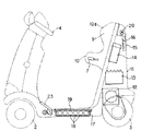
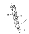
シートフレーム5の後側には、図1及び図2に示すように、後部カバー11を後側に張出して取付ける。後部カバー11内には、下側から、電動モーター12・コントローラー13・充電器14の順に配置し、上部にルーバー15を設けた放熱フアン16を取付ける。放熱フアン16とルーバー15は、図6に示すように、後部カバー11に上端を軸着してあって、上方に開くことができて、充電時に、充電器14のリールコード14aを引出すことができるようにしてある。放熱フアン16は、電動モーター12、コントローラー13の発熱を、ルーバー15を通して外部に放出する。
【0018】
フロアフレーム1の中央部には、図1及び図2に示すように、バッテリー収納部17を設けてバッテリー18を収容し、フロアカバー19で覆う。バッテリー18はNi−Cd,Ni−MH,Li−イオンのようなものを前提として、広くフラットなフロアの下に配置している。このフロア内のバッテリー収納部17は広いので大容量の電池を収容できるので、交換する必要がなくなる。また、車両の重心として考えても前後輪2,3の間の低い位置に配置するので良好である。バッテリーはフロアカバー(フロアマットでよい)19に閉ざされた空間のバッテリー収納部17に入れられ、その合せ面にあるシール材で密閉されている。フロアカバー19を上方から外せば電池の交換も容易に行うことができる。
【0019】
後部カバー11の上端には、図1及び図2に示すように、中央にストップランプ20を取付け、その両側に方向指示灯21を取付ける。
フロアフレーム1の前部の傾斜面には、図1に示すように、中央に幅広のブレーキペダル22を取付け、ブレーキペダル22の両側にアクセルペダル23を取付ける。又、この代りに図7に示すように踏込むとアクセルになり離すとブレーキがかかる幅広のアクセルブレーキ兼用ペダル24を取付けるようにしてもよい。なお、ステアリングはアッカーマン式を採用すると左右の前輪2の間に挟まれた空間はデッドスペースとなるが、そこにブレーキペダル22を中央に、その両側にアクセルペダル23を配置して、空間の有効利用している。また、前記のペダル22,23などは前輪のフェンダーからフロアに繋がる傾斜面に配置され、フットレストの代わりにもなるものである。
【0020】
乗員は、図8に示すように、シート10に浅く腰掛け、背当て9にもたれるようにして、立った姿勢に近い形で乗り、手でハンドル4を操作し、左右の何れかの足で、アクセルペダル23、ブレーキペダル22か、アクセルブレーキ兼用ペダル24を操作する。
【0021】
【発明の効果】
以上説明したように、この発明は上述のように構成したので、乗員はシートに浅く腰掛けて背当てにもたれるようにして立った姿勢に近い形で乗車するので疲労が少く、目線を高くできて視界がよく、又、横を歩く同伴者との目線も合せ易くて会話などに都合がよい。
そして、電動モーターやコントローラーなどは、後部カバー内に収容して体裁がよく、放熱フアンで換気もできる。
【0022】
又、アクセル、ブレーキは、左右何れの足でも操作できて都合がよく、ストップランプや方向指示灯を備えているので、周囲に意志の伝達ができ、公道でも安心して使用できる。
【図面の簡単な説明】
【図1】本発明の実施形態の電動車両を示す斜視図である。
【図2】本発明の実施形態で主として駆動系を示す側面図である。
【図3】本発明の実施形態で主としてフレーム、ハンドル、シート関係を示す側面図である。
【図4】本発明の実施形態を示すシート部分の側面図である。
【図5】本発明の実施形態を示すシート部分の平面図である。
【図6】本発明の実施形態を示す放熱フアン部分の縦断側面図である。
【図7】本発明の実施形態を示すアクセルブレーキ兼用ペダル部分を示す斜視図である。
【図8】本発明の実施形態を示す乗員の乗車姿勢を示す側面図である。
【符号の説明】
1 フロアフレーム
2 前輪
3 後輪
4 ハンドル
5 シートフレーム
6 シートポスト
7 レバー
9 背当て
10 シート
11 後部カバー
12 電動モーター
13 コントローラー
14 充電器
15 ルーバー
16 放熱フアン
17 バッテリー収納部
18 バッテリー
19 フロアカバー
20 ストップランプ
21 方向指示灯
22 ブレーキペダル
23 アクセルペダル
24 アクセルブレーキ兼用ペダル[0001]
BACKGROUND OF THE INVENTION
The present invention relates to an electric vehicle that is seated on a seat having a short front-rear dimension and is seated in a posture close to a standing posture so as to lean against a backrest.
[0002]
[Prior art]
The electric vehicle is a three-wheel or four-wheel, the front one wheel or the front two wheels are steered by the steering wheel, the rear two wheels are driven by the electric motor, and the battery, controller, electric motor, etc. are housed inside the cover provided at the rear, and the cover The driver sits on a seat attached to the upper surface of the car.
[0003]
Also, as a special one, there is one that gets on in an upright posture (see Japanese Patent Laid-Open No. 10-57425).
[0004]
[Problems to be solved by the invention]
A general electric vehicle is designed to sit on a seat provided on the upper surface of the rear cover that houses functional parts, and can be operated by sitting deeply on the seat. It is convenient for. However, when the person sits deeply, the line of sight becomes low, the field of view is inferior, and there is a companion who accompanies walking on the side, it is inconvenient for conversation.
[0005]
Further, the one disclosed in Japanese Patent Laid-Open No. 10-57425 that operates in a standing posture is good for use in a special place such as a hospital, but is not suitable for traveling on a public road.
[0006]
In view of this point, the present invention can be seated in a posture close to a standing posture that is shallowly seated on a seat with a short front-rear dimension and leans against a backrest, has a high line of sight, good visibility, and a companion who walks sideways. The purpose is to obtain an electric vehicle that is convenient for conversation and suitable for use on public roads.
[0007]
[Means for Solving the Problems]
In order to achieve the above object, the electric vehicle of the present invention has wheels arranged on the left and right front and rear sides of a floor frame that is raised front and rear, steers the front two wheels with a handle protruding upward, and uses the electric motor to drive the rear two wheels. In an electric vehicle that is driven and has a seat frame that protrudes upward at the rear, and a seat with a backrest is attached so that the vertical position can be adjusted ,
The seat can be adjusted in a vertical position to a height that allows the occupant to sit in a posture close to a standing posture. The occupant is provided with a pair of left and right holding portions that support the waist and the back of the occupant by projecting forward from both the left and right sides of the back portion while allowing the occupant to contact the back and back. It is in.
[0008]
According to the electric vehicle of the present invention, the passenger is sitting shallow sheet, so as to be leaning on the backrest, riding posture closer to the standing posture, can be reduced fatigue because the steering behind the wheel, the position of the eyes It is high and has a good field of view, and the height of the line of sight with a companion who walks alongside is close, making it convenient for conversations.
In addition, the seat can be adjusted up and down to a height that can be seated in a posture close to a standing posture in which the occupant is substantially upright, and the front and rear direction dimensions are shorter than those of a typical wheelchair seat. In the riding posture, the occupant can make contact with the back and back of the occupant, and has a pair of left and right holding parts that protrude forward from the left and right sides of the back part and support the occupant's waist and back. Therefore, it is convenient because the seat can be adjusted up and down according to the physique of the passenger and the eyes of the accompanying person.
In addition, the seat includes a backrest portion that is integrated with a slider that projects from the rear end portion of the seat underframe to the rear side of the backrest portion and extends along the backrest portion of the seat from the rear portion of the floor frame. A rear cover that covers the backrest of the seat from the rear side on the rear side of the seat frame. In this rear cover, an electric motor, a controller and a charger are arranged in order from the bottom, and an exhaust fan with a louver is provided at the top, so functional parts such as an electric motor are Since it is accommodated in the rear cover on the rear side of the seat frame, the appearance is good.
[0009]
The seat frame is tilted backwards so that the upper part is on the rear side, and the seat back is positioned on the front side of the rear wheel axle at the position where the seat is at the uppermost end. When a person gets on, the seat position is on the rear side, and the position relative to the steering wheel or the like can be kept in a good state, and the seat is on the front side with respect to the axis of the rear wheel, so the stability of the vehicle body is also good.
[0015]
A wide brake pedal provided in the front inclined surface center of the floor frame, with placing the accelerator pedal on the left and right sides, lever to wider than the accelerator pedal the brake pedal, in the left and right both legs, the accelerator It is convenient to operate the brake.
[0016]
DETAILED DESCRIPTION OF THE INVENTION
Hereinafter, an embodiment of the present invention will be described with reference to FIGS.
As shown in FIG. 3, the floor frame 1 has a generally U-shaped side view with the front and rear being high and the center portion being low, and a
A
As shown in FIG. 3 to FIG. 5, a reverse open
The seat post 6 (seat under frame) is mounted so that the
As described above, so that the
[0017]
As shown in FIGS. 1 and 2, the
[0018]
As shown in FIGS. 1 and 2, the
[0019]
As shown in FIGS. 1 and 2, a
As shown in FIG. 1, a
[0020]
As shown in FIG. 8, the occupant sits shallowly on the
[0021]
【The invention's effect】
As described above, since the present invention is configured as described above, the occupant sits shallowly on the seat and leans on the back so that the occupant rides in a posture close to the standing posture, so that there is less fatigue and a high eye-gaze. The field of view is good, and it is easy to match the line of sight with a companion walking sideways, which is convenient for conversation.
And the electric motor, controller, etc. are housed in the rear cover and look good and can be ventilated with a heat dissipation fan.
[0022]
In addition, the accelerator and brake can be operated with either the left or right foot, and are conveniently equipped with a stop lamp and direction indicator light, so that the will can be transmitted to the surroundings and used safely on public roads.
[Brief description of the drawings]
FIG. 1 is a perspective view showing an electric vehicle according to an embodiment of the present invention.
FIG. 2 is a side view mainly showing a drive system in the embodiment of the present invention.
FIG. 3 is a side view mainly showing a relationship between a frame, a handle and a seat in the embodiment of the present invention.
FIG. 4 is a side view of a seat portion showing an embodiment of the present invention.
FIG. 5 is a plan view of a seat portion showing an embodiment of the present invention.
FIG. 6 is a longitudinal sectional side view of a heat dissipation fan portion showing an embodiment of the present invention.
FIG. 7 is a perspective view showing an accelerator brake combined pedal portion showing the embodiment of the present invention.
FIG. 8 is a side view showing the riding posture of the occupant showing the embodiment of the present invention.
[Explanation of symbols]
DESCRIPTION OF SYMBOLS 1
Claims (4)
前記シートは、乗員が略起立した立ち姿勢に近い姿勢で腰掛け可能な高さに上下位置を調節可能にし、前後方向の寸法を一般的な車椅子のシートより短く形成して前記略起立した乗車姿勢で乗員が腰や背中を背あて部に当接可能にするとともに、前記背あて部の左右両側から前方に突出して乗員の腰や背中を包むように支持する左右一対の保持部を備えていることを特徴とする電動車両。Wheels are arranged on the left and right front and back of the raised floor frame, the front two wheels are steered by the handle protruding upward, the rear two wheels are driven by an electric motor, and the seat frame that protrudes upward is provided at the rear. In an electric vehicle in which the abutting seat is mounted so that the vertical position can be adjusted ,
The seat can be adjusted in a vertical position to a height that allows the occupant to sit in a posture close to a standing posture. The occupant is provided with a pair of left and right holding portions that support the waist and the back of the occupant by projecting forward from both the left and right sides of the back portion while allowing the occupant to contact the back and back. electric vehicle according to claim.
フロアフレームの後部からシートの背あて部に沿って延在するシートフレームが立設され、このシートフレームに前記シートのスライダーが外周に摺接して上下に摺動可能に取付けられ、
シートフレームの後側に前記シートの背あて部を後側から覆う後部カバーが設けられ、この後部カバーには、内部に電動モーターとコントローラーと充電器を下側から順に配設するとともに、上部にルーバーを設けた排気ファンを設けたことを特徴とする請求項1記載の電動車両。The seat includes a slider provided integrally with a backrest portion and projecting to a rear end portion of the seat underframe on the rear side of the backrest portion,
A seat frame extending along the backrest portion of the seat from the rear portion of the floor frame is erected, and the slider of the seat is slidably attached to the outer periphery of the seat frame so as to be slidable up and down,
Rear cover is provided for covering the rear side backrest portion of the seat on the rear side of the seat frame, this rear cover, with sequentially arranged electric motor and controller and the charger from the lower side to the inner portion, the upper electric vehicle according to claim 1, characterized in that a exhaust fan which is provided with louvers.
Priority Applications (6)
| Application Number | Priority Date | Filing Date | Title |
|---|---|---|---|
| JP2000230250A JP4045725B2 (en) | 2000-07-31 | 2000-07-31 | Electric vehicle |
| US09/897,147 US6655483B2 (en) | 2000-07-31 | 2001-06-29 | Electric motor vehicle |
| TW090116056A TW592683B (en) | 2000-07-31 | 2001-06-29 | Electric motor vehicle |
| DE60118065T DE60118065T2 (en) | 2000-07-31 | 2001-07-28 | electric vehicle |
| EP01118207A EP1177972B1 (en) | 2000-07-31 | 2001-07-28 | Electric motor vehicle |
| CNB011244666A CN1277525C (en) | 2000-07-31 | 2001-07-31 | Electric vehicle |
Applications Claiming Priority (1)
| Application Number | Priority Date | Filing Date | Title |
|---|---|---|---|
| JP2000230250A JP4045725B2 (en) | 2000-07-31 | 2000-07-31 | Electric vehicle |
Publications (3)
| Publication Number | Publication Date |
|---|---|
| JP2002035048A JP2002035048A (en) | 2002-02-05 |
| JP2002035048A5 JP2002035048A5 (en) | 2005-07-07 |
| JP4045725B2 true JP4045725B2 (en) | 2008-02-13 |
Family
ID=18723235
Family Applications (1)
| Application Number | Title | Priority Date | Filing Date |
|---|---|---|---|
| JP2000230250A Expired - Fee Related JP4045725B2 (en) | 2000-07-31 | 2000-07-31 | Electric vehicle |
Country Status (6)
| Country | Link |
|---|---|
| US (1) | US6655483B2 (en) |
| EP (1) | EP1177972B1 (en) |
| JP (1) | JP4045725B2 (en) |
| CN (1) | CN1277525C (en) |
| DE (1) | DE60118065T2 (en) |
| TW (1) | TW592683B (en) |
Families Citing this family (20)
| Publication number | Priority date | Publication date | Assignee | Title |
|---|---|---|---|---|
| TWI233800B (en) * | 2002-02-12 | 2005-06-11 | Suzuki Motor Co | Miniature electromotive vehicle |
| JP4214759B2 (en) * | 2002-10-29 | 2009-01-28 | スズキ株式会社 | Electric rough terrain vehicle |
| US7865275B2 (en) * | 2003-10-10 | 2011-01-04 | Dynamic Controls Limited | Method and apparatus for controlling an electric vehicle function |
| JP2005132525A (en) * | 2003-10-29 | 2005-05-26 | Toyota Industries Corp | Backrest structure for standing ride type driver's platform in industrial vehicle |
| JP4463639B2 (en) * | 2004-08-06 | 2010-05-19 | 本田技研工業株式会社 | Cooling structure for electric vehicles |
| JP5071711B2 (en) * | 2007-07-20 | 2012-11-14 | 本田技研工業株式会社 | Straddle-type electric vehicle |
| US7699130B2 (en) * | 2007-09-14 | 2010-04-20 | Anna Palmer | Wheeled vehicle |
| EP2473364B1 (en) | 2009-08-31 | 2019-09-25 | Multiple Electric Systems, L.L.C. | Multiple induction electric motor and vehicle |
| WO2012035739A1 (en) * | 2010-09-13 | 2012-03-22 | パナソニック株式会社 | Boarded mobile body and method for controlling boarded mobile body |
| NL2005526C2 (en) * | 2010-10-15 | 2012-04-17 | Rudolf Wilhelm Johannes Schmidt | Scooter, in particular a mobility scooter, for driving while standing or semi-standing, having two front wheels and a single rear wheel. |
| JP5840846B2 (en) * | 2011-02-25 | 2016-01-06 | 本田技研工業株式会社 | Storage structure for power connection for saddle riding type vehicles |
| FR2975895B1 (en) * | 2011-05-30 | 2013-06-28 | Commissariat Energie Atomique | VEHICLE HAS AT LEAST THREE STABLE SUPPORT POINTS ON THE GROUND |
| JP2013071547A (en) * | 2011-09-27 | 2013-04-22 | Honda Motor Co Ltd | Electric vehicle |
| EP2796349A1 (en) * | 2011-12-22 | 2014-10-29 | Yamaha Hatsudoki Kabushiki Kaisha | Saddle-ridden electric vehicle |
| WO2014054069A1 (en) * | 2012-10-03 | 2014-04-10 | 川崎重工業株式会社 | Electric vehicle, and battery pack |
| US9806587B2 (en) | 2013-08-26 | 2017-10-31 | Robert Ross | System and method for stator construction of an electric motor |
| JP6200762B2 (en) * | 2013-10-11 | 2017-09-20 | 本田技研工業株式会社 | Electric vehicle |
| TWI647130B (en) * | 2017-08-28 | 2019-01-11 | 財團法人工業技術研究院 | Electric vehicle and control method thereof |
| CN108820089B (en) * | 2018-08-10 | 2023-08-04 | 上海智租物联科技有限公司 | Electric bicycle |
| KR102636313B1 (en) * | 2021-08-18 | 2024-02-14 | 주식회사 힐스로보틱스 | Self driving electric wheelchair |
Family Cites Families (27)
| Publication number | Priority date | Publication date | Assignee | Title |
|---|---|---|---|---|
| US3043389A (en) * | 1960-04-11 | 1962-07-10 | Max R Steinberg | Power driven riding golf cart |
| US3168156A (en) * | 1962-01-11 | 1965-02-02 | Yale & Towne Inc | Steering and control handle |
| US3166282A (en) * | 1962-02-13 | 1965-01-19 | American Radiator & Standard | Bathlift device |
| US3419116A (en) * | 1965-12-14 | 1968-12-31 | Panto Vittorio | Device for operating the control of both brake and accelerator of an automobile by single pedal |
| US3305264A (en) * | 1966-01-17 | 1967-02-21 | M H Spinks Sr Entpr Inc | Adjustable aircraft seat |
| US4042055A (en) * | 1975-12-18 | 1977-08-16 | Ward Eugene T | Battery powered vehicle and drive system |
| US4332415A (en) * | 1978-10-12 | 1982-06-01 | Williams Thomas P | Open cart roof structure |
| DE3238597C2 (en) * | 1982-10-19 | 1984-10-25 | Dr.Ing.H.C. F. Porsche Ag, 7000 Stuttgart | Forklift |
| US5033564A (en) * | 1990-02-20 | 1991-07-23 | Floor Style Products, Inc. | Power riding trailer for an implement |
| US5341894A (en) * | 1993-04-22 | 1994-08-30 | Gorder Jr John E Van | Golf cart for ambulatory disadvantaged golfers |
| US5518081A (en) * | 1993-07-15 | 1996-05-21 | Thibodeau; Bryan H. | All-terrain, all-weather wheelchair |
| JP3347426B2 (en) * | 1993-10-19 | 2002-11-20 | 本田技研工業株式会社 | Cooling structure of electric vehicle charger |
| WO1996005585A1 (en) * | 1994-08-15 | 1996-02-22 | Robert Anthony Kerby | Vehicle control simulator |
| GB2306139B (en) * | 1995-10-11 | 1999-05-26 | Terrapid Technologies Cc | A vehicle |
| JP3764524B2 (en) * | 1996-04-22 | 2006-04-12 | 本田技研工業株式会社 | Small vehicle |
| JPH09309343A (en) | 1996-05-22 | 1997-12-02 | Honda Motor Co Ltd | Motor driven vehicle |
| US5947222A (en) * | 1996-07-31 | 1999-09-07 | Honda Giken Kogyo Kabushiki Kaisha | Three-wheeled automobile |
| JP3544071B2 (en) * | 1996-08-22 | 2004-07-21 | 日野自動車株式会社 | Electric vehicle that can be driven in a standing position |
| US6042170A (en) * | 1996-08-23 | 2000-03-28 | Honda Giken Kogyo Kabushiki Kaisha | Light vehicle |
| TW350825B (en) * | 1996-12-06 | 1999-01-21 | Citymobil Ag | Motor-driven 3-wheeled vehicle |
| US5950751A (en) * | 1997-07-29 | 1999-09-14 | Solorider Industries, Inc. | Electrically-powered vehicle with swivel seat |
| US5960901A (en) * | 1997-09-04 | 1999-10-05 | Corbin Pacific, Inc. | Battery-powered vehicle |
| CA2222434C (en) * | 1997-11-26 | 2006-07-25 | Ricci Tools Inc. | Louver assembly with multi-position louver adjusting control rod having clamping connecting arms |
| JP3250510B2 (en) * | 1998-02-06 | 2002-01-28 | 株式会社豊田自動織機 | Battery forklift |
| WO2000046056A1 (en) * | 1999-02-05 | 2000-08-10 | Powerlight Corporation | Electric vehicle photovoltaic charging system |
| US6293610B1 (en) * | 2000-02-01 | 2001-09-25 | Jayne A. Howard | Method and apparatus for a door system for golf cart-type street vehicle |
| US6345676B1 (en) * | 2000-02-07 | 2002-02-12 | Mattel, Inc. | Bubble-producing ride-on vehicle |
-
2000
- 2000-07-31 JP JP2000230250A patent/JP4045725B2/en not_active Expired - Fee Related
-
2001
- 2001-06-29 US US09/897,147 patent/US6655483B2/en not_active Expired - Lifetime
- 2001-06-29 TW TW090116056A patent/TW592683B/en not_active IP Right Cessation
- 2001-07-28 DE DE60118065T patent/DE60118065T2/en not_active Expired - Lifetime
- 2001-07-28 EP EP01118207A patent/EP1177972B1/en not_active Expired - Lifetime
- 2001-07-31 CN CNB011244666A patent/CN1277525C/en not_active Expired - Fee Related
Also Published As
| Publication number | Publication date |
|---|---|
| DE60118065T2 (en) | 2006-09-14 |
| DE60118065D1 (en) | 2006-05-11 |
| CN1336164A (en) | 2002-02-20 |
| US6655483B2 (en) | 2003-12-02 |
| JP2002035048A (en) | 2002-02-05 |
| CN1277525C (en) | 2006-10-04 |
| EP1177972A2 (en) | 2002-02-06 |
| TW592683B (en) | 2004-06-21 |
| EP1177972B1 (en) | 2006-03-22 |
| US20020020570A1 (en) | 2002-02-21 |
| EP1177972A3 (en) | 2004-06-09 |
Similar Documents
| Publication | Publication Date | Title |
|---|---|---|
| JP4045725B2 (en) | Electric vehicle | |
| JPS638081A (en) | Low floor small vehicle | |
| TWI248891B (en) | Vehicular seat structure | |
| JP2008044552A (en) | Floor structure of off-road traveling four-wheel vehicle | |
| JP3395007B2 (en) | Self-propelled vehicle | |
| JP4529629B2 (en) | Direction indicator for small electric vehicle | |
| KR102092539B1 (en) | Safety bar device for electric carts | |
| JP2560174Y2 (en) | Electric tricycle | |
| JP3544071B2 (en) | Electric vehicle that can be driven in a standing position | |
| KR20190087852A (en) | Silver carriage for four-wheel | |
| JP2019073156A (en) | Electric vehicle | |
| JP7374370B1 (en) | electric mobility | |
| KR102159666B1 (en) | Electric wheelchair with auxiliary footrest | |
| JP3081958B2 (en) | Body structure of electric tricycle | |
| JP2005323692A (en) | Motor-driven wheelchair | |
| JP2627958B2 (en) | Electric tricycle | |
| JPS6260315B2 (en) | ||
| JPH11115858A (en) | Small vehicle | |
| JPH04131227U (en) | electric tricycle | |
| NL2005526C2 (en) | Scooter, in particular a mobility scooter, for driving while standing or semi-standing, having two front wheels and a single rear wheel. | |
| JP2519807Y2 (en) | Electric three-wheel wheelchair | |
| JPH0613307B2 (en) | Auxiliary footrest device for scooter type vehicles | |
| JPH09315343A (en) | Chassis and body structure of motor-driven four-wheel vehicle | |
| JP2587639Y2 (en) | Electric wheelchair seat structure | |
| JP2004209037A (en) | Electric motor vehicle |
Legal Events
| Date | Code | Title | Description |
|---|---|---|---|
| A521 | Request for written amendment filed |
Free format text: JAPANESE INTERMEDIATE CODE: A523 Effective date: 20041109 |
|
| A621 | Written request for application examination |
Free format text: JAPANESE INTERMEDIATE CODE: A621 Effective date: 20041109 |
|
| A977 | Report on retrieval |
Free format text: JAPANESE INTERMEDIATE CODE: A971007 Effective date: 20070221 |
|
| A131 | Notification of reasons for refusal |
Free format text: JAPANESE INTERMEDIATE CODE: A131 Effective date: 20070710 |
|
| A521 | Request for written amendment filed |
Free format text: JAPANESE INTERMEDIATE CODE: A523 Effective date: 20070904 |
|
| TRDD | Decision of grant or rejection written | ||
| A01 | Written decision to grant a patent or to grant a registration (utility model) |
Free format text: JAPANESE INTERMEDIATE CODE: A01 Effective date: 20071030 |
|
| A61 | First payment of annual fees (during grant procedure) |
Free format text: JAPANESE INTERMEDIATE CODE: A61 Effective date: 20071112 |
|
| FPAY | Renewal fee payment (event date is renewal date of database) |
Free format text: PAYMENT UNTIL: 20101130 Year of fee payment: 3 |
|
| R151 | Written notification of patent or utility model registration |
Ref document number: 4045725 Country of ref document: JP Free format text: JAPANESE INTERMEDIATE CODE: R151 |
|
| FPAY | Renewal fee payment (event date is renewal date of database) |
Free format text: PAYMENT UNTIL: 20101130 Year of fee payment: 3 |
|
| FPAY | Renewal fee payment (event date is renewal date of database) |
Free format text: PAYMENT UNTIL: 20111130 Year of fee payment: 4 |
|
| FPAY | Renewal fee payment (event date is renewal date of database) |
Free format text: PAYMENT UNTIL: 20121130 Year of fee payment: 5 |
|
| FPAY | Renewal fee payment (event date is renewal date of database) |
Free format text: PAYMENT UNTIL: 20121130 Year of fee payment: 5 |
|
| FPAY | Renewal fee payment (event date is renewal date of database) |
Free format text: PAYMENT UNTIL: 20131130 Year of fee payment: 6 |
|
| LAPS | Cancellation because of no payment of annual fees |