EP2903494B1 - Disposable endoscopy and biopsy system - Google Patents
Disposable endoscopy and biopsy system Download PDFInfo
- Publication number
- EP2903494B1 EP2903494B1 EP13782688.9A EP13782688A EP2903494B1 EP 2903494 B1 EP2903494 B1 EP 2903494B1 EP 13782688 A EP13782688 A EP 13782688A EP 2903494 B1 EP2903494 B1 EP 2903494B1
- Authority
- EP
- European Patent Office
- Prior art keywords
- disposable
- tube
- distal end
- forceps
- biopsy forceps
- Prior art date
- Legal status (The legal status is an assumption and is not a legal conclusion. Google has not performed a legal analysis and makes no representation as to the accuracy of the status listed.)
- Not-in-force
Links
Images


Classifications
-
- A—HUMAN NECESSITIES
- A61—MEDICAL OR VETERINARY SCIENCE; HYGIENE
- A61B—DIAGNOSIS; SURGERY; IDENTIFICATION
- A61B1/00—Instruments for performing medical examinations of the interior of cavities or tubes of the body by visual or photographical inspection, e.g. endoscopes; Illuminating arrangements therefor
- A61B1/00064—Constructional details of the endoscope body
- A61B1/00071—Insertion part of the endoscope body
- A61B1/0008—Insertion part of the endoscope body characterised by distal tip features
- A61B1/00087—Tools
-
- A—HUMAN NECESSITIES
- A61—MEDICAL OR VETERINARY SCIENCE; HYGIENE
- A61B—DIAGNOSIS; SURGERY; IDENTIFICATION
- A61B1/00—Instruments for performing medical examinations of the interior of cavities or tubes of the body by visual or photographical inspection, e.g. endoscopes; Illuminating arrangements therefor
- A61B1/00064—Constructional details of the endoscope body
- A61B1/00071—Insertion part of the endoscope body
- A61B1/0008—Insertion part of the endoscope body characterised by distal tip features
- A61B1/00101—Insertion part of the endoscope body characterised by distal tip features the distal tip features being detachable
-
- A—HUMAN NECESSITIES
- A61—MEDICAL OR VETERINARY SCIENCE; HYGIENE
- A61B—DIAGNOSIS; SURGERY; IDENTIFICATION
- A61B1/00—Instruments for performing medical examinations of the interior of cavities or tubes of the body by visual or photographical inspection, e.g. endoscopes; Illuminating arrangements therefor
- A61B1/00131—Accessories for endoscopes
- A61B1/00135—Oversleeves mounted on the endoscope prior to insertion
-
- A—HUMAN NECESSITIES
- A61—MEDICAL OR VETERINARY SCIENCE; HYGIENE
- A61B—DIAGNOSIS; SURGERY; IDENTIFICATION
- A61B1/00—Instruments for performing medical examinations of the interior of cavities or tubes of the body by visual or photographical inspection, e.g. endoscopes; Illuminating arrangements therefor
- A61B1/00142—Instruments for performing medical examinations of the interior of cavities or tubes of the body by visual or photographical inspection, e.g. endoscopes; Illuminating arrangements therefor with means for preventing contamination, e.g. by using a sanitary sheath
- A61B1/00144—Hygienic packaging
-
- A—HUMAN NECESSITIES
- A61—MEDICAL OR VETERINARY SCIENCE; HYGIENE
- A61B—DIAGNOSIS; SURGERY; IDENTIFICATION
- A61B1/00—Instruments for performing medical examinations of the interior of cavities or tubes of the body by visual or photographical inspection, e.g. endoscopes; Illuminating arrangements therefor
- A61B1/012—Instruments for performing medical examinations of the interior of cavities or tubes of the body by visual or photographical inspection, e.g. endoscopes; Illuminating arrangements therefor characterised by internal passages or accessories therefor
- A61B1/018—Instruments for performing medical examinations of the interior of cavities or tubes of the body by visual or photographical inspection, e.g. endoscopes; Illuminating arrangements therefor characterised by internal passages or accessories therefor for receiving instruments
-
- A—HUMAN NECESSITIES
- A61—MEDICAL OR VETERINARY SCIENCE; HYGIENE
- A61B—DIAGNOSIS; SURGERY; IDENTIFICATION
- A61B1/00—Instruments for performing medical examinations of the interior of cavities or tubes of the body by visual or photographical inspection, e.g. endoscopes; Illuminating arrangements therefor
- A61B1/273—Instruments for performing medical examinations of the interior of cavities or tubes of the body by visual or photographical inspection, e.g. endoscopes; Illuminating arrangements therefor for the upper alimentary canal, e.g. oesophagoscopes, gastroscopes
- A61B1/2733—Oesophagoscopes
-
- A—HUMAN NECESSITIES
- A61—MEDICAL OR VETERINARY SCIENCE; HYGIENE
- A61B—DIAGNOSIS; SURGERY; IDENTIFICATION
- A61B1/00—Instruments for performing medical examinations of the interior of cavities or tubes of the body by visual or photographical inspection, e.g. endoscopes; Illuminating arrangements therefor
- A61B1/273—Instruments for performing medical examinations of the interior of cavities or tubes of the body by visual or photographical inspection, e.g. endoscopes; Illuminating arrangements therefor for the upper alimentary canal, e.g. oesophagoscopes, gastroscopes
- A61B1/2736—Gastroscopes
-
- A—HUMAN NECESSITIES
- A61—MEDICAL OR VETERINARY SCIENCE; HYGIENE
- A61B—DIAGNOSIS; SURGERY; IDENTIFICATION
- A61B10/00—Other methods or instruments for diagnosis, e.g. instruments for taking a cell sample, for biopsy, for vaccination diagnosis; Sex determination; Ovulation-period determination; Throat striking implements
- A61B10/02—Instruments for taking cell samples or for biopsy
- A61B10/04—Endoscopic instruments
-
- A—HUMAN NECESSITIES
- A61—MEDICAL OR VETERINARY SCIENCE; HYGIENE
- A61B—DIAGNOSIS; SURGERY; IDENTIFICATION
- A61B10/00—Other methods or instruments for diagnosis, e.g. instruments for taking a cell sample, for biopsy, for vaccination diagnosis; Sex determination; Ovulation-period determination; Throat striking implements
- A61B10/02—Instruments for taking cell samples or for biopsy
- A61B10/06—Biopsy forceps, e.g. with cup-shaped jaws
Definitions
- a disposable tube of the type mentioned is generally from the WO 2008/101653 A2 and the DE 10 2010 049 568 A1 is known, to whose respective disclosure content expressly referred.
- the US 2006/0149131 A1 discloses a wrapping device which is attached to a proximal port of the working channel of an endoscope and, upon retraction of a biopsy forceps, releases a flexible sheath surrounding the shaft of the biopsy forceps.
- distal and proximal in the context of the present invention refer to the perspective of the operator (treating physician), i. the distal end of the disposable tube is the free end away from the operator.
- said locking projection is an integral portion of the disposable tube or the pliers head, which is biased due to its inherent elasticity in the direction of an engagement position to engage in the engaged position in said locking recess.
- said detent projection is a separate element movably mounted on the disposable hose or plier head and biased toward an engagement position by biasing means (e.g., spring member).
- the latching projection may be, for example, a locking screen biased radially outwards or at least one locking arm of the pliers head. When the disposable biopsy forceps reach the working position, the latching projection may be e.g. relax and engage with the associated latching recess. The disposable biopsy forceps is thus in operative connection with the disposable tube.
- the fastening device is adapted to produce in said working position a magnetic coupling between the distal end of the disposable tube and the forceps head, wherein at the distal end of the disposable tube at least one permanent magnet and at the pliers head at least one associated magnetic counter-element are provided or vice versa.
- the counter element can be paramagnetic and / or magnetizable his. This allows temporary attachment of the disposable biopsy forceps to the disposable tube.
- the fastening device is adapted to release the pliers head from the distal end of the disposable tube upon application of a forceps head with a predetermined force from said working position.
- the predetermined force can be an axial force with respect to the longitudinal axis of the disposable tube, as a result of which the temporary attachment of the disposable biopsy forceps to the disposable tube can be released from a certain threshold.
- the power transmission to the pliers head can be done for example by means of the Bowden cable soul.
- the release of the pliers head for example, can only be done with force in the proximal direction.
- the Bowdenzugseele the disposable biopsy forceps on a soul of metal and (at least in sections) a hereby firmly connected jacket made of plastic.
- a plastic sheath can prevent unwanted cutting of the Bowden cable in the disposable tube which peripherally delimits the working channel, in particular in the case of strong curvatures such as the aforementioned inversion. This may prove to be important if, as already explained, no conventional guide sleeve is used to guide the Bowden cable core, but instead it is replaced by the working channel of the disposable tube.
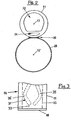
- Fig. 3 shows a detailed view of the distal end 14 of the disposable tube 11 (corresponding to the area B according to FIG Fig. 1a during a phase of configuring the disposable system 10 for subsequent use.
- the cover provided there 18 initially seals the working channel 22 (shown in phantom) completely, so that the working channel 22 is opened only at the proximal end 16 of the disposable tube 11.
- the cover 18 is formed in the embodiment shown here by a film, which compared to the diameter of the disposable tube 11 and also in comparison to the wall thickness of the disposable tube 11 (in the peripheral region of the smallest wall thickness according to Fig. 2 ) is relatively thin.
Description
Die Erfindung betrifft ein Endoskopie- und Biopsie-Einwegsystem, mit einem Einwegschlauch, der zumindest einen Arbeitskanal umgibt und der Endoskopbefestigungsmittel zum Befestigen des Einwegschlauchs an einem Endoskop aufweist, und wenigstens einer Einwegbiopsiezange, die in den Arbeitskanal einführbar oder eingeführt ist, wobei die Einwegbiopsiezange einen Zangenkopf mit wenigstens zwei beweglichen Backen und eine Bowdenzugseele zum Betätigen der Backen aufweist.The invention relates to a disposable endoscopy and biopsy system comprising a disposable tube surrounding at least one working channel and having endoscope attachment means for attaching the disposable tube to an endoscope, and at least one disposable biopsy forceps insertable or inserted into the working channel, the disposable biopsy forceps Pliers head having at least two movable jaws and a Bowden cable soul for actuating the jaws.
Der Einwegschlauch einschließlich des Arbeitskanals kann dabei über die Endoskopbefestigungsmittel seitlich am Endoskop befestigt werden. Die Endoskopbefestigungsmittel umfassen beispielsweise eine Fixiereinrichtung für ein drehfestes und axial festes Fixieren am distalen Ende des Endoskops und/oder eine oder mehrere Führungsschlaufen, die für eine längsverschiebliche Befestigung beabstandet voneinander entlang der Länge des Einwegschlauchs angeordnet sind.The disposable tube including the working channel can be fastened laterally on the endoscope via the endoscope attachment means. The endoscope attachment means comprise, for example, a fixing device for a rotationally fixed and axially fixed fixing at the distal end of the endoscope and / or one or more guide loops, which are arranged for a longitudinally displaceable attachment spaced from each other along the length of the disposable tube.
Die Biopsiezange kann zur Entnahme einer Gewebeprobe dienen, beispielsweise aus der Speiseröhre (Ösophagus) oder aus dem Magen des Patienten, insbesondere zum Zwecke einer histologischen Untersuchung. Durch die Verwendung eines Einwegschlauchs mit Arbeitskanal wird die Notwendigkeit eines Endoskops vermieden, das einen integrierten Arbeitskanal besitzt und deshalb unter hygienischen Gesichtspunkten unerwünscht sein kann. Mit Hilfe der Endoskopbefestigungsmittel kann der Einwegschlauch an einem Endoskop befestigt werden. Somit kann als Endoskop ein einfaches Fibroskop oder Videoendoskop verwendet werden, das abgesehen von den erforderlichen Bowdenzügen lediglich einen optischen oder elektronischen Beobachtungskanal (jedoch keinen integrierten Arbeitskanal) umfasst und somit einen vorteilhaft geringen Querschnitt besitzt. Ein derartiges Endoskop mitsamt dem genannten Einwegsystem kann dem Patienten z.B. oral oder nasal eingeführt werden.The biopsy forceps can be used to take a tissue sample, for example from the esophagus or from the stomach of the patient, in particular for the purpose of histological examination. The use of a disposable tube with working channel avoids the need for an endoscope that has an integrated working channel and therefore may be undesirable from a hygienic point of view. With the help of the endoscope attachment means, the disposable tube can be attached to an endoscope. Thus, a simple fibroscope or video endoscope can be used as endoscope, that apart from the required Bowden cables only an optical or electronic observation channel (but no integrated working channel) and thus has an advantageously low profile. Such an endoscope together with the aforementioned disposable system can be introduced to the patient, for example orally or nasally.
Ein Einwegschlauch der genannten Art ist generell aus der
Die Bowdenzugseele der Biopsiezange kann als ein Betätigungsdraht ausgebildet sein, vorzugsweise aus Metall. Die Bowdenzugseele ist bei einer herkömmlichen Biopsiezange innerhalb einer Führungshülle längsbeweglich geführt, die mit dem Zangenkopf fest verbunden ist. Am distalen Ende der Biopsiezange kann die Bowdenzugseele an die beweglichen Backen des Zangenkopfes unmittelbar oder mittelbar, beispielsweise über eine Umlenk- oder Übersetzungseinrichtung, gekoppelt sein. Bei geschlossenen Backen kann der Außendurchmesser des Zangenkopfes beispielsweise höchstens so groß wie der Innendurchmesser des Arbeitskanals sein. Dadurch wird ein Ein- und/oder Ausführen der Bowdenzugseele in den Arbeitskanal ermöglicht.The Bowden cable core of the biopsy forceps can be designed as an actuating wire, preferably made of metal. The Bowden cable is longitudinally movably guided in a conventional biopsy forceps within a guide sleeve, which is firmly connected to the pliers head. At the distal end of the biopsy forceps, the Bowdenzugseele can be directly or indirectly, for example via a deflection or translation device, coupled to the movable jaws of the pliers head. With closed jaws, the outer diameter of the pliers head, for example, at most be as large as the inner diameter of the working channel. This makes it possible to connect and / or execute the Bowden cable in the working channel.
Das zugeordnete Endoskop kann - wie bereits erwähnt - einen Beobachtungskanal, insbesondere einen elektronischen Videokanal oder einen optischen Kanal, mit einer Empfangsoptik am distalen Ende umfassen. Ferner kann das zugeordnete Endoskop eine Bowdenzug-Steuereinrichtung zum Krümmen des Endoskops in zwei gewünschte Richtungen umfassen. Dadurch können entsprechende Beobachtungen, Probenentnahmen und/oder ein Saugen oder Spülen in diesen Richtungen erfolgen. Insbesondere kann ein so genanntes Invertieren der Endoskopspitze erfolgen (auch als Inversion bezeichnet), d.h. eine Krümmung um etwa 200° oder nahezu 200°.As already mentioned, the associated endoscope can comprise an observation channel, in particular an electronic video channel or an optical channel, with a receiving optics at the distal end. Further, the associated endoscope may include a Bowden cable controller for curving the endoscope in two desired directions. This allows appropriate observations, Sampling and / or sucking or rinsing in these directions take place. In particular, a so-called inversion of the endoscope tip can take place (also referred to as inversion), ie a curvature of about 200 ° or nearly 200 °.
Hierbei ist insbesondere wichtig, dass der Einwegschlauch mit dem Arbeitskanal der Krümmung der Endoskopspitze folgen kann, obwohl sich für den Einwegschlauch und die Endoskopspitze unterschiedliche Krümmungsradien ergeben. Dies wird durch die Fixierung am distalen Ende des Endoskops einerseits und die verschiebliche Befestigung entlang der Längserstreckung des Endoskops andererseits ermöglicht.It is particularly important here that the disposable tube with the working channel can follow the curvature of the endoscope tip, although different radii of curvature result for the disposable tube and the endoscope tip. This is made possible by the fixation at the distal end of the endoscope on the one hand and the displaceable attachment along the longitudinal extension of the endoscope on the other hand.
Problematisch gestaltet sich hierbei jedoch die Steifigkeit einer handelsüblichen Biopsiezange, insbesondere an deren distalem Ende. Dabei auftretende Rückstellkräfte können beispielsweise zu groß sein, um mittels der Bowdenzug-Steuereinrichtung des Endoskops die gewünschten Krümmungsradien des Endoskops einschließlich des Einwegschlauchs und der darin befindlichen Biopsiezange einstellen zu können. Ein weiteres Problem bei der Verwendung einer herkömmlichen Biopsiezange besteht generell unter hygienischen Gesichtspunkten in der schwierigen Reinigung nach der Behandlung.The problem here, however, the stiffness of a standard biopsy forceps designed, especially at the distal end. Occurring restoring forces, for example, be too large to be able to adjust by means of the Bowden cable control device of the endoscope, the desired radii of curvature of the endoscope including the disposable tube and the biopsy forceps therein. Another problem with the use of conventional biopsy forceps is generally hygienic in the difficult post-treatment cleaning.
Es ist eine Aufgabe der Erfindung, die freie Beweglichkeit des Endoskops bei Verwendung eines Einwegschlauchs und einer Biopsiezange noch weiter zu verbessern.It is an object of the invention to further improve the free mobility of the endoscope when using a disposable tube and a biopsy forceps.
Die Lösung dieser Aufgabe erfolgt durch ein Endoskopie- und Biopsie-Einwegsystem mit den Merkmalen des Anspruchs 1 sowie durch ein Verfahren mit den Merkmalen des Anspruchs 11.The solution of this object is achieved by an endoscopy and biopsy disposable system with the features of claim 1 and by a method having the features of
Das erfindungsgemäße Einwegsystem umfasst eine Befestigungseinrichtung zum temporären oder permanenten Befestigen des Zangenkopfes am distalen Ende des Einwegschlauchs in einer Arbeitsposition, in der zumindest die Backen des Zangenkopfes über das distale Ende des Einwegschlauchs hervorragen. Auch ein Teil des Zangenkopfes kann in der Arbeitsposition über das distale Ende des Einwegschlauchs überstehen. Mit anderen Worten ist die Befestigungseinrichtung als Fixpunkt für eine relative Bewegung zwischen der Bowdenzugseele und dem Einwegschlauch und zum Unterbinden einer Bewegung des Zangenkopfes relativ zu dem Einwegschlauch ausgebildet. Somit ist eine Einwegbiopsiezange in den Arbeitskanal des Einwegschlauchs integriert, insbesondere ohne dass eine zusätzliche Führung zwingend erforderlich ist, wie nachstehend noch näher erläutert wird.The disposable system according to the invention comprises a fastening device for temporary or permanent attachment of the pliers head on distal end of the disposable tube in a working position in which at least the jaws of the forceps head protrude beyond the distal end of the disposable tube. Also, a part of the pliers head can survive in the working position on the distal end of the disposable tube. In other words, the fastening device is designed as a fixed point for relative movement between the Bowden cable core and the disposable tube and for preventing movement of the pliers head relative to the disposable tube. Thus, a disposable biopsy forceps is integrated into the working channel of the disposable tube, in particular without an additional guide is absolutely necessary, as will be explained in more detail below.
Auf diese Weise ergibt sich ein verbessertes Krümmungsverhalten, da zum Führen der Bowdenzugseele der Biopsiezange keine herkömmliche Führungshülle zwingend benötigt wird. Herkömmliche Führungshüllen sind unflexibel und steif, da sie typischerweise aus Metall gefertigt sind, wodurch insbesondere das erläuterte Invertieren nicht oder nur sehr schwer möglich ist. Bei dem erfindungsgemäßen Einwegsystem kann die Führungshülle teilweise oder vollständig durch den Arbeitskanal des Einwegschlauchs ersetzt sein, oder es wird lediglich eine dünne und/oder weiche Führungshülle verwendet, deren Funktion bei Benutzung der Einwegbiopsiezange durch den umgebenden Einwegschlauch unterstützt wird. Der Einwegschlauch kann insbesondere ein Kunststoffmaterial umfassen und somit weich sein, während eine ausreichende Knickfestigkeit oder eine Knickcharakteristik erreicht wird, die eine Beweglichkeit der Bowdenzugseele gewährleistet. Lediglich im äußersten Bereich des distalen Endes des Einwegschlauchs, also wo die Fixiereinrichtung für die Endoskopspitze , die Befestigungseinrichtung für den Zangenkopf und der Zangenkopf selbst vorgesehen sind, ist der Einwegschlauch vergleichsweise steif. Somit wird im Falle der genannten Inversion dieser äußerste, relativ steife Bereich des Einwegschlauchs umgeschwenkt.In this way, there is an improved curvature behavior, since no conventional guide sleeve is mandatory for guiding the Bowden cable of the biopsy forceps. Conventional guide sheaths are inflexible and stiff, since they are typically made of metal, whereby in particular the explained inversion is impossible or very difficult. In the disposable system according to the invention, the guide sheath may be partially or completely replaced by the working channel of the disposable tube, or only a thin and / or soft guide sheath is used whose function is supported by the surrounding disposable tube when using the disposable biopsy forceps. The disposable tube may in particular comprise a plastic material and thus be soft, while a sufficient kink resistance or a kinking characteristic is achieved, which ensures a mobility of the Bowden cable soul. Only in the outermost region of the distal end of the disposable tube, ie where the fixing device for the endoscope tip, the fastening device for the pliers head and the pliers head are provided itself, the disposable tube is relatively stiff. Thus, in the case of said inversion, this outermost, relatively stiff region of the disposable tube is swung around.
Hygieneprobleme, die bei herkömmlichen Biopsiezangen im Zusammenhang mit einer unzureichenden Reinigung auftreten können, werden durch das erfindungsgemäße Einwegsystem unterbunden, da dieses nicht mehrfach verwendet wird, sondern nach dem einmaligen Gebrauch entsorgt wird. Dies gilt sowohl für den Einwegschlauch als auch für die Einwegbiopsiezange.Hygiene problems that may occur in conventional biopsy forceps in connection with insufficient cleaning are prevented by the disposable system according to the invention, since this is not used several times, but is disposed of after a single use. This applies to both the disposable tube and the disposable biopsy forceps.
Die Bezeichnungen "distal" und "proximal" beziehen sich im Zusammenhang mit der vorliegenden Erfindung auf die Perspektive der Bedienperson (behandelnder Arzt), d.h. das distale Ende des Einwegschlauchs ist das freie, von der Bedienperson weg gelegene Ende.The terms "distal" and "proximal" in the context of the present invention refer to the perspective of the operator (treating physician), i. the distal end of the disposable tube is the free end away from the operator.
Weiterbildungen der Erfindung sind den abhängigen Ansprüchen, der Beschreibung sowie den beigefügten Zeichnungen zu entnehmen.Further developments of the invention can be found in the dependent claims, the description and the accompanying drawings.
Gemäß einer Ausführungsform ist die Befestigungseinrichtung an dem Zangenkopf und/oder an dem distalen Ende des Einwegschlauchs vorgesehen. Die Befestigungseinrichtung kann somit auch teilweise am Zangenkopf und teilweise am distalen Ende des Einwegschlauchs angeordnet sein. Insbesondere ist die Befestigungseinrichtung weiter proximal als die Backen der Einwegbiopsiezange angeordnet. Auf diese Weise bleiben die Backen bei einer Betätigung der Einwegbiopsiezange bezüglich des Einwegschlauchs insbesondere ortsfest und werden beispielsweise nicht in den Einwegschlauch hineingezogen.According to one embodiment, the fastening device is provided on the pliers head and / or on the distal end of the disposable tube. The fastening device can thus also be arranged partially on the pliers head and partly on the distal end of the disposable tube. In particular, the fastening device is arranged more proximally than the jaws of the disposable biopsy forceps. In this way, when the disposable biopsy forceps are actuated with respect to the disposable tube, the jaws in particular remain stationary and, for example, are not drawn into the disposable tube.
Bei einer bevorzugten Ausführungsform ist die Befestigungseinrichtung dazu angepasst, den Zangenkopf in der Arbeitsposition am distalen Ende des Einwegschlauchs zwar axial fest, jedoch drehbeweglich zu befestigen. Mit anderen Worten ist der Zangenkopf bei dieser Ausführungsform entlang der Längsachse des Einwegschlauchs in fester Position am distalen Ende des Einwegschlauchs befestigt (temporär oder dauerhaft). Um die Längsachse des Einwegschlauchs herum ist der Zangenkopf allerdings drehbar (durchgängig oder zumindest um einen bestimmten Drehwinkel). Somit ist die gesamte Einwegzange (einschließlich der Bowdenzugseele) innerhalb des Arbeitskanals drehbar gelagert. Beispielsweise kann an dem einen Teil (Zangenkopf oder Einwegschlauch, insbesondere am Innenumfang des Arbeitskanals) eine Ringnut vorgesehen sein, in die wenigstens ein Befestigungselement des jeweiligen anderen Teils (Einwegschlauch oder Zangenkopf) eingreift, beispielsweise ein oder mehrere Befestigungszapfen, Befestigungsnasen oder Befestigungsstege.In a preferred embodiment, the fastening device is adapted to the pliers head in the working position at the distal end Although the disposable tube axially fixed, but rotatably secure. In other words, in this embodiment, the forceps head is secured (temporarily or permanently) along the longitudinal axis of the disposable tube in a fixed position at the distal end of the disposable tube. However, around the longitudinal axis of the disposable tube around the pliers head is rotatable (continuous or at least by a certain angle of rotation). Thus, the entire disposable forceps (including the Bowden cable) is rotatably mounted within the working channel. For example, on the one part (pliers head or disposable hose, in particular on the inner circumference of the working channel) an annular groove may be provided, into which at least one fastening element of the respective other part (disposable hose or pliers head) engages, for example one or more fastening pins, fastening lugs or fastening webs.
Hierdurch ist es möglich, die Ausrichtung (d.h. die Winkelstellung) der Zangenbacken auch in der Arbeitsposition noch zu ändern, um eine Anpassung an die Umgebung (für ein verbessertes Erfassen der zu entnehmenden Gewebeprobe) und eine bessere Beobachtbarkeit (mittels des Beobachtungskanals des Endoskops) zu gestatten. Beispielsweise kann der Benutzer vom proximalen Ende des Einwegschlauchs aus den Zangenkopf durch Verdrehen der Bowdenzugseele drehen. Insbesondere im Falle der genannten Inversion ist dies von Vorteil.This makes it possible to change the orientation (ie the angular position) of the forceps jaws even in the working position in order to adapt to the environment (for improved detection of the tissue sample to be taken) and better observability (by means of the observation channel of the endoscope) allow. For example, from the proximal end of the disposable tube, the user may rotate the forceps head by twisting the Bowden cable core. In particular, in the case of said inversion, this is advantageous.
Nach einer vorteilhaften Ausführungsform ist die Befestigungseinrichtung dazu angepasst, in der genannten Arbeitsposition einen Rastschluss (d.h. eine Schnappverbindung) zwischen dem distalen Ende des Einwegschlauchs und dem Zangenkopf herzustellen, wobei an dem distalen Ende des Einwegschlauchs wenigstens ein Rastvorsprung und an dem Zangenkopf wenigstens eine zugeordnete Rastvertiefung vorgesehen sind oder umgekehrt. Der Rastschluss kann insbesondere durch eine nach innen gerichtete, ringförmige Einschnürung oder durch mehrere Nasen am Ende und/oder an der Innenseite des Einwegschlauchs gebildet werden, welche mit einer zugeordneten Ringnut am Zangenkopf zusammenwirkt bzw. zusammenwirken. Durch den Rastschluss wird sowohl eine proximale als auch distale Bewegung der Backen des Zangenkopfes relativ zum Einwegschlauch unterbunden.According to an advantageous embodiment, the fastening device is adapted to produce in said working position a snap fit (ie a snap connection) between the distal end of the disposable tube and the pliers head, wherein at the distal end of the disposable tube at least one latching projection and at the pliers head at least one associated latching recess are provided or vice versa. The latching can in particular by an inward directed, annular constriction or by a plurality of lugs at the end and / or on the inside of the disposable tube are formed, which cooperates or cooperate with an associated annular groove on the pliers head. The latching closure prevents both proximal and distal movement of the jaws of the forceps head relative to the disposable tube.
In einer Weiterbildung ist der genannte Rastvorsprung ein integraler Abschnitt des Einwegschlauchs oder des Zangenkopfes, der aufgrund von Eigenelastizität in Richtung einer Eingriffsstellung vorgespannt ist, um in der Eingriffsstellung in die genannte Rastvertiefung einzugreifen. Alternativ ist der genannte Rastvorsprung ein separates Element, das an dem Einwegschlauch oder dem Zangenkopf beweglich gelagert und mittels einer Vorspanneinrichtung (z.B. Federelement) in Richtung einer Eingriffsstellung vorgespannt ist. Bei dem Rastvorsprung kann es sich beispielsweise um einen radial nach außen vorgespannten Arretierschirm oder zumindest einen Arretierarm des Zangenkopfes handeln. Erreicht die Einwegbiopsiezange die Arbeitsposition, so kann sich der Rastvorsprung z.B. entspannen und mit der zugeordneten Rastvertiefung verrasten. Die Einwegbiopsiezange steht damit mit dem Einwegschlauch in Wirkverbindung.In a development, said locking projection is an integral portion of the disposable tube or the pliers head, which is biased due to its inherent elasticity in the direction of an engagement position to engage in the engaged position in said locking recess. Alternatively, said detent projection is a separate element movably mounted on the disposable hose or plier head and biased toward an engagement position by biasing means (e.g., spring member). The latching projection may be, for example, a locking screen biased radially outwards or at least one locking arm of the pliers head. When the disposable biopsy forceps reach the working position, the latching projection may be e.g. relax and engage with the associated latching recess. The disposable biopsy forceps is thus in operative connection with the disposable tube.
Gemäß einer weiteren Ausführungsform ist die Befestigungseinrichtung dazu angepasst, in der genannten Arbeitsposition eine magnetische Kopplung zwischen dem distalen Ende des Einwegschlauchs und dem Zangenkopf herzustellen, wobei an dem distalen Ende des Einwegschlauchs wenigstens ein Permanentmagnet und an dem Zangenkopf wenigstens ein zugeordnetes magnetisches Gegenelement vorgesehen sind oder umgekehrt. Das Gegenelement kann dabei paramagnetisch und/oder magnetisierbar sein. Dadurch kann ein temporäres Befestigen der Einwegbiopsiezange an dem Einwegschlauch erreicht werden.According to a further embodiment, the fastening device is adapted to produce in said working position a magnetic coupling between the distal end of the disposable tube and the forceps head, wherein at the distal end of the disposable tube at least one permanent magnet and at the pliers head at least one associated magnetic counter-element are provided or vice versa. The counter element can be paramagnetic and / or magnetizable his. This allows temporary attachment of the disposable biopsy forceps to the disposable tube.
Nach einer weiteren Ausführungsform ist die Befestigungseinrichtung dazu angepasst, bei Beaufschlagung eines Zangenkopfes mit einer vorbestimmten Kraft ausgehend von der genannten Arbeitsposition den Zangenkopf von dem distalen Ende des Einwegschlauchs freizugeben. Bei der vorbestimmten Kraft kann es sich um eine bezüglich der Längsachse des Einwegschlauchs axiale Kraft handeln, aufgrund derer ab einer bestimmten Schwelle die temporäre Befestigung der Einwegbiopsiezange am Einwegschlauch gelöst werden kann. Die Kraftübertragung auf den Zangenkopf kann beispielsweise mittels der Bowdenzugseele erfolgen. Insbesondere aufgrund einer entsprechenden Formgebung einer Rastnase kann das Lösen des Zangenkopfes beispielsweise nur bei Krafteinwirkung in proximaler Richtung erfolgen. Bei einer Krafteinwirkung in distaler Richtung kann der Zangenkopf weiterhin am distalen Ende des Einwegschlauchs fixiert sein. Aufgrund einer derartigen Lösbarkeit des Zangenkopfes von dem distalen Ende des Einwegschlauchs ist es insbesondere möglich, mehrere verschiedene Einwegbiopsiezangen nacheinander in den Einwegschlauch einzuführen und zur Probenentnahme an verschiedenen Positionen innerhalb des Körpers des Patienten zu verwenden, während der Einwegschlauch selbst während des Wechsels der Einwegbiopsiezangen im Körper verbleibt.According to a further embodiment, the fastening device is adapted to release the pliers head from the distal end of the disposable tube upon application of a forceps head with a predetermined force from said working position. The predetermined force can be an axial force with respect to the longitudinal axis of the disposable tube, as a result of which the temporary attachment of the disposable biopsy forceps to the disposable tube can be released from a certain threshold. The power transmission to the pliers head can be done for example by means of the Bowden cable soul. In particular, due to a corresponding shaping of a detent, the release of the pliers head, for example, can only be done with force in the proximal direction. With a force acting in the distal direction, the pliers head can continue to be fixed to the distal end of the disposable tube. In particular, due to such releasability of the forceps head from the distal end of the disposable tube, it is possible to insert several different disposable biopsy forceps sequentially into the disposable tube and use it for sampling at various locations within the patient's body while the disposable tube itself is in the body during the change of disposable biopsy forceps remains.
Alternativ zu einer temporären Befestigung ist auch eine permanente Befestigung denkbar, wobei die Befestigungsmittel beider Varianten vorzugsweise derart ausgebildet sind, dass sie die Sicht des am Einwegschlauch angeordneten Endoskops nicht beeinträchtigen.As an alternative to a temporary attachment, a permanent attachment is also conceivable, wherein the attachment means of both variants are preferably designed such that they do not impair the view of the endoscope disposed on the disposable tube.
Gemäß einer Ausführungsform weist die Befestigungseinrichtung zum permanenten Befestigen des Zangenkopfes am distalen Ende des Einwegschlauchs ein stoffschlüssiges, formschlüssiges und/oder kraftschlüssiges Verbundmittel auf. Das stoffschlüssige Verbundmittel kann beispielsweise ein Klebemittel oder eine Schweißverbindung umfassen, um eine starre Verbindung herzustellen. Das formschlüssige Verbundmittel kann beispielsweise eine Bördelung aufweisen. Das kraftschlüssige Verbundmittel kann beispielsweise eine Schrumpfverbindung, eine Pressverbindung oder einen Klemmsitz umfassen. Der Zangenkopf der Einwegbiopsiezange kann somit bereits im Auslieferungszustand des Einwegsystems mit dem Einwegschlauch dauerhaft verbunden sein. Die Befestigungseinrichtung kann bei manchen Ausführungsformen in der Arbeitsposition z.B. zumindest abschnittsweise radial über den Innenradius des Arbeitskanals hervorragen. Ein Zurückziehen der Einwegbiopsiezange aus dem Arbeitskanal wird dadurch unterbunden.According to one embodiment, the fastening device for permanent attachment of the pliers head at the distal end of the disposable tube on a cohesive, positive and / or non-positive composite means. The cohesive composite may comprise, for example, an adhesive or a welded joint to form a rigid connection. The form-fitting composite means may, for example, have a flange. The non-positive connection means may comprise, for example, a shrink connection, a press connection or a press fit. The pliers head of the disposable biopsy forceps can thus be permanently connected to the disposable tube already in the delivery state of the disposable system. The fastening device may in some embodiments in the working position e.g. protrude radially at least in sections over the inner radius of the working channel. Retraction of the disposable biopsy forceps from the working channel is thereby prevented.
Gemäß einer besonders vorteilhaften Ausführungsform weist das Einwegsystem ferner eine Einführröhre auf, die ausgehend von dem proximalen Ende des Einwegschlauchs gemeinsam mit der Biopsiezange in den Arbeitskanal einführbar ist, um den Zangenkopf in die Arbeitsposition zu bringen, wobei die Einführröhre in dem eingeführten Zustand die Bowdenzugseele umgibt, und wobei die Einführröhre vor der bestimmungsgemäßen Benutzung der Einwegbiopsiezange wieder aus dem Arbeitskanal nach proximal entfernt werden kann, während der Zangenkopf sich in der Arbeitsposition befindet. Die Einführröhre ist somit mit einem Trokar vergleichbar, welcher ebenfalls wieder entnommen werden kann. Eine derartige Einführröhre kann die Bowdenzugseele für ein Versetzen des Zangenkopfes entlang des Arbeitskanals bis zu der Arbeitsposition am distalen Ende des Einwegschlauchs stabilisieren. Die Einführröhre ist jedoch im Unterschied zu der bereits genannten Führungshülle einer herkömmlichen Biopsiezange nicht für die bestimmungsgemäße Benutzung der Einwegbiopsiezange erforderlich. Die Einführröhre kann vorzugsweise ein Kunststoffmaterial umfassen und/oder flexibel sein und z.B. als Schlauch, Rohr oder Tubus ausgebildet sein.According to a particularly advantageous embodiment, the disposable system further comprises an insertion tube, which is introduced from the proximal end of the disposable tube together with the biopsy forceps into the working channel to bring the pliers head in the working position, wherein the insertion tube surrounds the Bowden cable in the inserted state and wherein the introducer tube can be removed proximally from the working channel prior to the intended use of the disposable biopsy forceps while the forceps head is in the working position. The insertion tube is thus comparable to a trocar, which can also be removed again. Such an introducer tube may stabilize the Bowden cable core for displacing the forceps head along the working channel to the working position at the distal end of the disposable tube. However, unlike the already mentioned guide sleeve, the insertion tube is a conventional one Biopsy forceps not required for the intended use of disposable biopsy forceps. The insertion tube may preferably comprise a plastic material and / or be flexible and be designed, for example, as a tube, tube or tube.
Sofern - wie bereits erläutert - der Zangenkopf am distalen Ende des Einwegschlauchs drehbeweglich befestigt ist, kann die genannte Einführröhre auch zum Verdrehen des Zangenkopfes vom proximalen Ende des Einwegschlauchs aus verwendet werden. Hierfür kann an dem distalen Ende der Einführröhre ein Eingriffsmittel (z.B. eine Verzahnung) vorgesehen sein, das mit einem zugeordneten Gegeneingriffsmittel (z.B. passende Gegenverzahnung) an dem Zangenkopf zusammenwirkt, um die Übertragung einer Drehbewegung zu gestatten.If, as already explained, the forceps head is rotatably mounted on the distal end of the disposable tube, said insertion tube can also be used to rotate the forceps head from the proximal end of the disposable tube. For this purpose, engagement means (e.g., gearing) may be provided at the distal end of the introducer tube which cooperates with associated mating engagement means (e.g., mating mating teeth) on the forceps head to permit transmission of rotational motion.
Sofern alternativ zu einer derartigen Einführröhre die Einwegbiopsiezange eine Führungshülle aufweist, die dauerhaft mit dem Zangenkopf verbunden ist, so besteht die Führungshülle vorzugsweise aus einem weichen und dünnen Kunststoff.If, as an alternative to such an insertion tube, the disposable biopsy forceps has a guide sleeve which is permanently connected to the forceps head, the guide sleeve preferably consists of a soft and thin plastic.
Nach einer weiteren Ausführungsform weist das Einwegsystem ferner eine Betätigungseinrichtung zum Versetzen der Bowdenzugseele relativ zu dem Einwegschlauch auf, wobei die Betätigungseinrichtung wenigstens einen Gehäuseabschnitt aufweist, der an einer Koppeleinrichtung am proximalen Ende des Einwegschlauchs befestigbar ist, und wobei die Betätigungseinrichtung ferner wenigstens einen Antriebsabschnitt aufweist, der relativ zu dem Gehäuseabschnitt beweglich gelagert ist und der am proximalen Ende der Bowdenzugseele befestigbar ist. Durch manuelles Versetzen des Antriebsabschnitts relativ zu dem Gehäuseabschnitt können somit die Backen der Einwegbiopsiezange wahlweise geöffnet oder geschlossen werden.According to a further embodiment, the disposable system further comprises an actuating device for displacing the Bowden cable core relative to the disposable tube, wherein the actuating device has at least one housing section which can be fastened to a coupling device at the proximal end of the disposable tube, and wherein the actuating device further comprises at least one drive section, which is movably mounted relative to the housing portion and which is attachable to the proximal end of the Bowden cable. Thus, by manually displacing the drive section relative to the housing section, the jaws of the disposable biopsy forceps can be selectively opened or closed.
Die Koppeleinrichtung zum Befestigen des Gehäuseabschnitts der Betätigungseinrichtung am proximalen Ende des Arbeitskanals des Einwegschlauchs kann beispielsweise ein Gewinde umfassen, das insbesondere nach Art eines Bajonettverschlusses wirken kann. Alternativ oder zusätzlich ist auch eine Rastverbindung denkbar. Die Befestigung des genannten Antriebsabschnitts der Betätigungseinrichtung an der Bowdenzugseele kann insbesondere mit Hilfe eines Klemmsitzes erfolgen, beispielsweise über ein Einlegen der Bowdenzugseele in eine Nut und ein einfaches Überklappen eines Klemmhebels. Die Betätigungseinrichtung kann insbesondere als Mehrwegteil ausgebildet sein, an dem die Bowdenzugseele und der Einwegschlauch lösbar befestigt werden können. Somit kann die Betätigungseinrichtung, die wesentlich einfacher als der Einwegschlauch zuverlässig gereinigt werden kann, mehrfach benutzt werden. Alternativ kann jedoch auch die Betätigungseinrichtung als Einwegteil ausgebildet sein.The coupling device for fastening the housing section of the actuating device at the proximal end of the working channel of the disposable tube can comprise, for example, a thread which can act in particular in the manner of a bayonet closure. Alternatively or additionally, a latching connection is conceivable. The attachment of said drive portion of the actuator to the Bowden cable soul can be done in particular by means of a clamping fit, for example via an insertion of the Bowden cable soul in a groove and a simple folding over a clamping lever. The actuating device can in particular be designed as a reusable part, to which the Bowden cable core and the disposable hose can be detachably fastened. Thus, the actuator, which can be cleaned much easier than the disposable hose reliably, be used several times. Alternatively, however, the actuator may be formed as a disposable part.
Gemäß einer vorteilhaften Ausführungsform weist die Bowdenzugseele der Einwegbiopsiezange eine Seele aus Metall und (zumindest abschnittsweise) einen hiermit fest verbundenen Mantel aus Kunststoff auf. Eine Ummantelung aus Kunststoff kann ein unerwünschtes Einschneiden der Bowdenzugseele in den den Arbeitskanal umfänglich begrenzenden Einwegschlauch verhindern, insbesondere bei starken Krümmungen wie der genannten Inversion. Dies kann sich als wichtig erweisen, wenn zum Führen der Bowdenzugseele - wie bereits erläutert - keine herkömmliche Führungshülle verwendet wird sondern diese durch den Arbeitskanal des Einwegschlauchs ersetzt ist.According to an advantageous embodiment, the Bowdenzugseele the disposable biopsy forceps on a soul of metal and (at least in sections) a hereby firmly connected jacket made of plastic. A plastic sheath can prevent unwanted cutting of the Bowden cable in the disposable tube which peripherally delimits the working channel, in particular in the case of strong curvatures such as the aforementioned inversion. This may prove to be important if, as already explained, no conventional guide sleeve is used to guide the Bowden cable core, but instead it is replaced by the working channel of the disposable tube.
Gemäß einer weiteren Ausführungsform weisen die Endoskopbefestigungsmittel eine Fixiereinrichtung auf, durch die der Einwegschlauch am distalen Ende des Endoskops drehfest und axial fixierbar ist, wobei die Endoskopbefestigungsmittel ferner wenigstens eine Führungseinrichtung aufweisen, durch die der Einwegschlauch an einem jeweiligen vom distalen Ende des Endoskops beabstandeten Abschnitt des Endoskops verschieblich befestigbar ist. Die Verbindung zwischen dem Endoskop und dem Einwegschlauch wird somit durch Endoskopbefestigungsmittel hergestellt, die einerseits eine Fixiereinrichtung und andererseits eine Führungseinrichtung umfassen. Die Fixiereinrichtung kann eine feste Verbindung zwischen dem Endoskop und dem Einwegschlauch herstellen, wodurch Relativbewegungen zwischen dem distalen Ende des Endoskops und dem Einwegschlauch unterbunden werden. Hierdurch ist gewährleistet, dass eine in der Umgebung der Fixiereinrichtung angeordnete Austrittsöffnung des Arbeitskanals im Einsatz des Endoskops und insbesondere auch bei einer Krümmung des Endoskops (z.B. aufgrund einer Betätigung eines Bowdenzugs) ihre Position relativ zu dem distalen Ende des Endoskops und der dort vorgesehenen Optik stets beibehält. Somit ist eine definierte Position einer seitlichen oder axialen Öffnung des Arbeitskanals relativ zu dem distalen Ende des Endoskops sichergestellt, was beispielsweise für das Absaugen von Sekreten oder für eine Probenentnahme mittels der Einwegbiopsiezange wichtig ist, wenn zugleich eine Beobachtung mittels des Endoskops erfolgen soll.According to a further embodiment, the endoscope fastening means have a fixing device, through which the disposable hose on distal end of the endoscope rotatably and axially fixed, the endoscope attachment means further comprise at least one guide means by which the disposable tube is slidably mounted on a respective spaced from the distal end of the endoscope section of the endoscope. The connection between the endoscope and the disposable tube is thus produced by endoscope fastening means, which on the one hand comprise a fixing device and on the other hand a guide device. The fixation device can establish a firm connection between the endoscope and the disposable tube, whereby relative movements between the distal end of the endoscope and the disposable tube are prevented. This ensures that an outlet opening of the working channel arranged in the vicinity of the fixing device always has its position relative to the distal end of the endoscope and the optics provided therein in use of the endoscope and in particular also in the case of a curvature of the endoscope (eg due to actuation of a Bowden cable) maintains. Thus, a defined position of a lateral or axial opening of the working channel is ensured relative to the distal end of the endoscope, which is important for example for the suction of secretions or for sampling by means of disposable biopsy forceps, if at the same time an observation should be made by means of the endoscope.
Demgegenüber erlaubt die Führungseinrichtung eine Relativbewegung zwischen dem Endoskop und dem Einwegschlauch. Dies ermöglicht Ausgleichsbewegungen in Längsrichtung (längsverschiebliche Befestigung) und/oder in Umfangsrichtung des Einwegschlauchs (drehbewegliche Befestigung), die aufgrund von während der Benutzung auftretenden Biegungen oder Krümmungen entlang der Einheit aus Endoskop und Einwegschlauch erforderlich sind. Darüber hinaus wird das Befestigen des Endoskops vereinfacht, da eine kraftschlüssige Fixierung in der Regel nur an einem Punkt des Endoskops - nämlich an dessen distalem Ende - erfolgt.In contrast, the guide device allows a relative movement between the endoscope and the disposable tube. This allows longitudinal (longitudinally displaceable attachment) and / or circumferential (or rotationally attachable) compensating movements to be required due to bends or bends occurring during use along the endoscope and disposable tube assembly. In addition, the attachment of the endoscope is simplified because a frictional fixation usually only at a point of the endoscope - namely at its distal end - takes place.
Nach einer weiteren Ausführungsform umgibt der Einwegschlauch zusätzlich wenigstens einen Spülkanal, wobei der Einwegschlauch an seinem distalen Ende eine Austrittsöffnung des Spülkanals aufweist. Die Austrittsöffnung kann bezüglich der Fixiereinrichtung für das distale Ende des Endoskops nach distal versetzt angeordnet sein. Somit ist beispielsweise sichergestellt, dass eine am distalen Ende des Endoskops befindliche Optik mittels einer durch den Spülkanal geführten Spülflüssigkeit stets zuverlässig gespült werden kann. Der Einwegschlauch umgibt in diesem Fall also zumindest zwei Kanäle, einen Arbeitskanal und einen Spülkanal. Die Austrittsöffnung des Spülkanals und die Öffnung des Arbeitskanals sind in einem Abschnitt des Einwegschlauchs angeordnet, der in distaler Richtung des Einwegschlauchs über die Fixiereinrichtung für das distale Ende des Endoskops hinausragt, wodurch ein effizientes Spülen einer am distalen Ende des Endoskops angeordneten Optik mittels einer aus der Austrittsöffnung des Spülkanals austretenden Spülflüssigkeit möglich ist. Außerdem können mittels des Arbeitskanals durchgeführte Tätigkeiten visuell durch das Endoskop kontrolliert werden. Gemäß einer Ausführungsform umfasst der Einwegschlauch zwei Spülkanäle, die bezüglich einer Mittenebene des Einwegschlauchs exzentrisch sowie symmetrisch zueinander angeordnet sind.According to a further embodiment, the disposable tube additionally surrounds at least one irrigation channel, wherein the disposable tube has an outlet opening of the flushing channel at its distal end. The outlet opening can be arranged offset distally relative to the fixing device for the distal end of the endoscope. Thus, for example, it is ensured that an optic located at the distal end of the endoscope can always be flushed reliably by means of a flushing fluid guided through the flushing channel. The disposable hose thus surrounds at least two channels, a working channel and a flushing channel in this case. The outlet opening of the flushing channel and the opening of the working channel are arranged in a portion of the disposable tube which protrudes in the distal direction of the disposable tube over the fixing device for the distal end of the endoscope, whereby an efficient flushing arranged at the distal end of the endoscope optics by means of one of Outlet opening of the flushing channel exiting rinsing liquid is possible. In addition, activities performed by the working channel can be visually inspected by the endoscope. According to one embodiment, the disposable tube comprises two flushing channels, which are arranged eccentrically with respect to a center plane of the disposable tube and symmetrically to each other.
Alternativ oder zusätzlich weist der Einwegschlauch an seinem distalen Ende eine Abdeckung auf, die den Arbeitskanal am distalen Ende des Einwegschlauchs abdichtet und die dazu ausgebildet ist, durch Krafteinwirkung mittels der in den Arbeitskanal eingeführten Einwegbiopsiezange geöffnet zu werden. Sobald also das Endoskop mitsamt dem Einwegsystem innerhalb des Körpers des Patienten an die gewünschte Untersuchungs- oder Behandlungsstelle gebracht worden ist (was mittels des optischen Kanals des Endoskops verifiziert werden kann), kann die den Arbeitskanal bis zu diesem Zeitpunkt abdichtende Abdeckung geöffnet werden, nämlich indem mittels der an der Rückseite der Abdeckung anliegenden Einwegbiopsiezange eine gewisse Kraft bzw. ein gewisser Druck auf die Abdeckung ausgeübt wird. Hierdurch reißt oder platzt die Abdeckung auf, oder sie löst sich teilweise oder vollständig von dem Einwegschlauch, so dass die Einwegbiopsiezange am distalen Ende des Einwegschlauchs aus dem Arbeitskanal herausgeführt werden kann. Nach dem Öffnen der Abdeckung kann unter Beobachtung mittels des optischen Kanals des Endoskops die gewünschte Probenentnahme erfolgen. Sobald beispielsweise eine geeignete Probe mittels der Einwegbiopsiezange erfasst worden ist, kann die Einwegbiopsiezange durch den Arbeitskanal des Einwegschlauchs hindurch vollständig dem Körper des Patienten entnommen werden, während das Endoskop und der hierin befestigte Einwegschlauch noch ihre Position im Körper des Patienten im Wesentlichen beibehalten.Alternatively or additionally, the disposable tube at its distal end on a cover which seals the working channel at the distal end of the disposable tube and which is adapted to be opened by force by means of the inserted into the working channel disposable biopsy forceps. So as soon as the endoscope together with the disposable system within the body of the patient to the desired examination or treatment site has been brought (which can be verified by means of the optical channel of the endoscope), the covering the working channel to this time sealing cover can be opened, namely by using the applied to the back of the cover disposable biopsy forceps a certain force or a certain pressure is exercised on the cover. This ruptures or bursts the cover, or it dissolves partially or completely from the disposable tube, so that the disposable biopsy forceps can be led out of the working channel at the distal end of the disposable tube. After opening the cover, the desired sampling can take place under observation by means of the optical channel of the endoscope. For example, once a suitable sample has been detected by the disposable biopsy forceps, the disposable biopsy forceps can be fully withdrawn through the working channel of the disposable tube to the body of the patient while the endoscope and disposable tube attached thereto still substantially maintain their position in the body of the patient.
Erst zu diesem Zeitpunkt der Entnahme der Biopsiezange dringen wesentliche Mengen der an der Untersuchungsstelle vorhandenen Körperflüssigkeit in den Arbeitskanal ein. Dies ist jedoch unkritisch, da diese Körperflüssigkeit ohnehin der Umgebung der entnommenen Probe entstammt. Durch die genannte Abdeckung wird jedoch vermieden, dass bereits während des Einführens des Einwegschlauchs in den Körper des Patienten (insbesondere entlang des Schlunds, des Rachens, des Ösophagus und/oder des Magens) Flüssigkeit aus anderen Körperbereichen als der beabsichtigten Untersuchungsstelle in den Arbeitskanal gelangt. Eine derartige Körperflüssigkeit könnte jedoch die nachfolgend in den Arbeitskanal eingeführte Einwegbiopsiezange oder eine nachfolgend durch den Arbeitskanal entnommene Probe verunreinigen. Der Arbeitskanal bleibt somit während des Einführens des Einwegschlauchs in den Körper des Patienten bis zu dem Durchstoßen oder sonstigen Öffnen der Abdeckung mittels der Einwegbiopsiezange steril. Ein weiterer Vorteil ist darin zu sehen, dass die Sterilität für den Benutzer anhand des Zustands der Abdeckung (noch nicht geöffnet) auch leicht erkennbar ist, d.h. der Benutzer und der Patient können ohne weiteres verifizieren, dass das Einwegsystem nicht bereits zu einem früheren Zeitpunkt benutzt worden ist. Durch die Vermeidung einer Kontamination des Arbeitskanals und die Erkennbarkeit einer früheren Benutzung des Einwegsystems ergeben sich also eine erhöhte Diagnosesicherheit und ein verbesserter Hygienegrad.Only at this time of removal of the biopsy forceps enter substantial amounts of existing at the examination site body fluid in the working channel. However, this is not critical, since this body fluid originates anyway the environment of the sample taken. By said cover, however, prevents even during insertion of the disposable tube into the body of the patient (especially along the pharynx, pharynx, esophagus and / or the stomach) liquid from other parts of the body than the intended examination point gets into the working channel. However, such bodily fluid could contaminate the disposable biopsy forceps subsequently inserted into the working channel or a sample subsequently withdrawn through the working channel. The working channel thus remains during insertion of the disposable tube into the body of the Patients sterile until piercing or otherwise opening the cover by means of the disposable biopsy forceps. Another advantage is that sterility to the user is also readily apparent from the condition of the cover (not yet opened), ie, the user and the patient can readily verify that the disposable system is not already in use at an earlier time has been. By avoiding contamination of the working channel and the recognizability of an earlier use of the disposable system thus results in an increased diagnostic reliability and improved hygiene.
Die Erfindung betrifft zudem ein Verfahren zum Konfigurieren eines Einwegsystems der erläuterten Art für eine nachfolgende bestimmungsgemäße Benutzung (Endoskopie und Biopsie), mit zumindest den folgenden Schritten: Einführen der Einwegbiopsiezange in den Arbeitskanal des Einwegschlauchs von dessen proximalem Ende aus, bis der Zangenkopf das distale Ende des Einwegschlauchs erreicht, und Befestigen des Zangenkopfes am distalen Ende des Einwegschlauchs in der Arbeitsposition. Der Zangenkopf wird somit in der Arbeitsposition fixiert, um eine relative Bewegung zwischen der Bowdenzugseele und dem Einwegschlauch und/oder eine proximale Bewegung des Zangenkopfes zu unterbinden.The invention also relates to a method of configuring a disposable system of the type described for subsequent intended use (endoscopy and biopsy) comprising at least the following steps: inserting the disposable biopsy forceps into the working channel of the disposable tube from its proximal end until the forceps head reaches the distal end reaches the disposable tube, and securing the pliers head at the distal end of the disposable tube in the working position. The pliers head is thus fixed in the working position to prevent relative movement between the Bowden cable soul and the disposable tube and / or a proximal movement of the pliers head.
Nach einer Weiterbildung dieses Verfahrens weist das Einwegsystem die genannte Einführröhre auf, wobei während des Schritts des Einführens der Einwegbiopsiezange in den Arbeitskanal des Einwegschlauchs die Einführröhre die Bowdenzugseele der Einwegbiopsiezange umgibt, und wobei nach dem Schritt des Einführens der Einwegbiopsiezange in den Arbeitskanal des Einwegschlauchs die Einführröhre wieder aus dem Arbeitskanal nach proximal entfernt wird. Die Einführröhre stabilisiert somit die Bowdenzugseele während des Einführens in den Arbeitskanal. Die Einführröhre wird vorzugsweise erst nach dem Schritt des Befestigens des Zangenkopfes in der Arbeitsposition entfernt. Nach dem Einführen der Einwegbiopsiezange in den Einwegschlauch kann die Einführröhre also auch das Versetzen des Zangenkopfes in die Arbeitsposition am distalen Ende des Einwegschlauchs unterstützen, insbesondere wenn die genannte Befestigungseinrichtung einen Rastschluss erzeugen soll. Vorzugsweise wird die Einführröhre vor der bestimmungsgemäßen Benutzung der Einwegbiopsiezange wieder aus dem Arbeitskanal herausgezogen. Alternativ ist auch denkbar, die Einführröhre nur teilweise nach proximal zurückzuziehen, oder die Einführröhre wird gänzlich im Einwegschlauch belassen und dient somit während einer nachfolgenden Benutzung der Einwegbiopsiezange als Führungshülle für die Bowdenzugseele.In a further development of this method, the disposable system comprises said introducer tube, wherein during the step of inserting the disposable biopsy forceps into the working channel of the disposable tube, the introducer tube surrounds the Bowden cable core of the disposable biopsy forceps, and after the step of inserting the disposable biopsy forceps into the working channel of the disposable tube, the introducer tube is again removed from the working channel to the proximal. The insertion tube thus stabilizes the Bowden cable soul during insertion into the working channel. The insertion tube is preferably after the step of attaching the Pliers head removed in the working position. Thus, after inserting the disposable biopsy forceps into the disposable tube, the introducer tube may also assist in displacing the forceps head into the working position at the distal end of the disposable tube, particularly if the noted fastener is to provide a snap fit. Preferably, the insertion tube is withdrawn from the working channel before the intended use of the disposable biopsy forceps. Alternatively, it is also conceivable to withdraw the insertion tube only partially to the proximal, or the insertion tube is left entirely in the disposable tube and thus serves as a guide shell for the Bowdenzugseele during subsequent use of disposable biopsy forceps.
Gemäß einer weiteren Ausführungsform weist das Einwegsystem die genannte Betätigungseinrichtung zum Versetzen der Bowdenzugseele relativ zu dem Einwegschlauch auf, wobei das Konfigurationsverfahren zusätzlich die folgenden Schritte umfasst, die nach dem Schritt des Befestigens des Zangenkopfes in der Arbeitsposition durchgeführt werden: Befestigen des Gehäuseabschnitts der Betätigungseinrichtung am proximalen Ende des Einwegschlauchs, und Befestigen des Antriebsabschnitts der Betätigungseinrichtung am proximalen Ende der Bowdenzugseele. Die Durchführung dieser weiteren Schritte erfolgt vorzugsweise nach Entfernen der Einführröhre, sofern eine solche benutzt wird.According to another embodiment, the disposable system comprises said actuator for displacing the Bowden cable core relative to the disposable tube, the configuration method additionally comprising the following steps performed after the step of securing the forceps head in the operative position: attaching the housing portion of the actuator to the proximal one End of the disposable tube, and attaching the drive portion of the actuator at the proximal end of the Bowden cable soul. The implementation of these further steps is preferably carried out after removal of the insertion tube, if one is used.
Nach einer weiteren Ausführungsform umfasst das Einwegsystem zusätzlich zu der genannten einen Einwegbiopsiezange wenigstens eine weitere Einwegbiopsiezange, die einen Zangenkopf mit wenigstens zwei beweglichen Backen und eine Bowdenzugseele zum Betätigen der Backen aufweist, wobei das Konfigurationsverfahren zusätzlich die folgenden Schritte umfasst: Lösen des Zangenkopfes der genannten einen Einwegbiopsiezange vom distalen Ende des Einwegschlauchs und Herausziehen der genannten einen Einwegbiopsiezange aus dem Arbeitskanal des Einwegschlauchs; Einführen der genannten weiteren Einwegbiopsiezange in den Arbeitskanal des Einwegschlauchs von dessen proximalem Ende aus, bis der Zangenkopf der genannten weiteren Einwegbiopsiezange das distale Ende des Einwegschlauchs erreicht; und Befestigen des Zangenkopfes der genannten weiteren Einwegbiopsiezange am distalen Ende des Einwegschlauchs in der Arbeitsposition. Dies ermöglicht insbesondere einen Wechsel der Einwegbiopsiezange während der Behandlung, d.h. während der Einwegschlauch im Körper des Patienten verbleibt, beispielsweise um mittels einer entsprechenden Anzahl von verschiedenen Einwegbiopsiezangen nacheinander mehrere Gewebeproben an verschiedenen Stellen im Körper zu entnehmen. Hierzu kann vor dem Lösen des Zangenkopfes der genannten einen Einwegbiopsiezange die genannte Betätigungseinrichtung entfernt werden, die nach dem Einführen und Befestigen der weiteren Einwegbiopsiezange wieder am Einwegschlauch angebracht werden kann.According to another embodiment, in addition to said disposable biopsy forceps, the disposable system comprises at least one further disposable biopsy forceps having a forceps head with at least two movable jaws and a Bowden cable core for operating the jaws, the configuration method additionally comprising the steps of: releasing the forceps head of said one Disposable biopsy forceps from the distal end of the disposable tube and withdrawing the aforementioned a disposable biopsy forceps from the working channel of the disposable tube; Inserting said further disposable biopsy forceps into the working channel of the disposable tube from the proximal end thereof until the forceps head of said further disposable biopsy forceps reaches the distal end of the disposable tube; and securing the forceps head of said further disposable biopsy forceps to the distal end of the disposable tube in the operative position. This makes it possible, in particular, to change the disposable biopsy forceps during the treatment, ie while the disposable tube remains in the body of the patient, for example to take a plurality of tissue samples at different locations in the body one after the other by means of a corresponding number of different disposable biopsy forceps. For this purpose, before the release of the pliers head of said one-way biopsy forceps, the said actuator can be removed, which can be attached to the disposable tube after inserting and attaching the other disposable biopsy forceps.
Bei dieser Ausführungsform mit wenigstens einer weiteren Einwegbiopsiezange kann das Einwegsystem eine Einführröhre aufweisen, insbesondere die bereits genannte Einführröhre (für die genannte eine Einwegbiopsiezange) oder eine weitere Einführröhre. Während des Schritts des Einführens der genannten weiteren Einwegbiopsiezange in den Arbeitskanal des Einwegschlauchs umgibt die Einführröhre die Bowdenzugseele der genannten weiteren Einwegbiopsiezange, um die Bowdenzugseele während des Einführens in den Arbeitskanal zu stabilisieren und den Zangenkopf mittels der Einführröhre nach vorne drücken zu können. Nach dem Schritt des Einführens der genannten weiteren Einwegbiopsiezange in den Arbeitskanal wird die Einführröhre wieder aus dem Arbeitskanal nach proximal entfernt, wobei dies vorzugsweise erst nach dem Schritt des Befestigens des Zangenkopfes in der Arbeitsposition und noch vor der bestimmungsgemäßen Benutzung der genannten weiteren Einwegbiopsiezange geschieht.In this embodiment with at least one further disposable biopsy forceps, the disposable system may comprise an introducer tube, in particular the aforementioned introducer tube (for said one-way biopsy forceps) or another introducer tube. During the step of introducing said further disposable biopsy forceps into the working channel of the disposable tube, the introducer tube surrounds the Bowden cable core of said other disposable biopsy forceps to stabilize the Bowden cable during insertion into the working channel and push the forceps head forward by means of the introducer tube. After the step of introducing the said further disposable biopsy forceps into the working channel, the introducer tube is again removed proximally from the working channel, preferably only after the step of securing the forceps head in the working position and before the intended Use of said other disposable biopsy forceps done.
Die Erfindung wird im Folgenden beispielhaft unter Bezugnahme auf die Zeichnungen erläutert. Es zeigen:
- Fig. 1a
- eine schematische Darstellung eines Endoskopie- und Biopsie-Einwegsystems,
- Fig. 1b
- eine um 90° gedrehte Ansicht des Einwegsystems gemäß
Fig. 1a , - Fig. 2
- einen Schnitt durch das Einwegsystem gemäß
Fig. 1a entlang der Ebene A-A, - Fig. 3
- eine Detailansicht des Bereichs B des Einwegsystems gemäß
Fig. 1a vor Erreichen der Arbeitsposition, - Fig. 4
- eine Detailansicht des Bereichs B des Einwegsystems gemäß
Fig. 1a in der Arbeitsposition mit einer ersten Ausführungsform einer Befestigungseinrichtung, - Fig. 5
- eine Detailansicht des Bereichs B des Einwegsystems gemäß
Fig. 1a in einer Arbeitsposition mit einer zweiten Ausführungsform einer Befestigungseinrichtung, - Fig. 6
- eine Detailansicht des Bereichs B des Einwegsystems gemäß
Fig. 1a in einer Arbeitsposition mit einer dritten Ausführungsform einer Befestigungseinrichtung, - Fig. 7
- eine Detailansicht des Bereichs B des Einwegsystems gemäß
Fig. 1a in einer Arbeitsposition mit einer vierten Ausführungsform einer Befestigungseinrichtung, und - Fig. 8
- eine Detailansicht des proximalen Endes eines Einwegsystems gemäß
Fig. 1a und 1b mit einer Betätigungseinrichtung.
- Fig. 1a
- a schematic representation of an endoscopy and biopsy disposable system,
- Fig. 1b
- a rotated by 90 ° view of the disposable system according to
Fig. 1a . - Fig. 2
- a section through the disposable system according to
Fig. 1a along the plane AA, - Fig. 3
- a detailed view of the area B of the disposable system according to
Fig. 1a before reaching the working position, - Fig. 4
- a detailed view of the area B of the disposable system according to
Fig. 1a in the working position with a first embodiment of a fastening device, - Fig. 5
- a detailed view of the area B of the disposable system according to
Fig. 1a in a working position with a second embodiment of a fastening device, - Fig. 6
- a detailed view of the area B of the disposable system according to
Fig. 1a in a working position with a third embodiment of a fastening device, - Fig. 7
- a detailed view of the area B of the disposable system according to
Fig. 1a in a working position with a fourth embodiment of a fastening device, and - Fig. 8
- a detailed view of the proximal end of a disposable system according to
Fig. 1a and 1b with an actuating device.
Durch die räumliche Nähe zu der Fixiermanschette 26 und die schlitzartige Formgebung der als Düse wirkenden Austrittsöffnung 20 kann Spülflüssigkeit auf die Optik eines in der Fixiermanschette 26 gehaltenen Endoskops gesprüht werden, um diese zu reinigen und beispielsweise störendes Sekret zu entfernen. Alternativ hierzu kann auch Luft durch den Spülkanal 24 geführt werden, um nicht nur die Optik des Endoskops frei zu blasen, sondern um durch Luftinsufflation auch den zu untersuchenden Hohlraum aufzublasen, so dass eine Wand beispielsweise des Magens besser beobachtet werden kann.Due to the spatial proximity to the fixing
Zusätzlich zu der Fixiermanschette 26 sind in regelmäßigen Abständen mehrere Führungsschlaufen 28 an dem Einwegschlauch 11 des Einwegsystems 10 angebracht, welche als Führungseinrichtungen dienen. Die Fixiermanschette 26 und die Führungsschlaufen 28 besitzen bei geradlinig ausgerichtetem Einwegschlauch 11 eine gemeinsame Längsachse 12'.In addition to the fixation sleeve 26 a plurality of
Im unteren Teil der Darstellung gemäß
Mit Bezug wiederum auf
Der Spülkanal 24 und die zugeordnete Austrittsöffnung 20 können auch entfallen. Ebenso können die erläuterten Endoskopiebefestigungsmittel (Fixiermanschette 26 und Führungsschlaufe 28) auch andersartig ausgebildet sein.The flushing
Ein besonderer Vorteil der Abdeckung 18 besteht auch darin, dass nach dem Öffnen die verbleibenden Abschnitte der Abdeckung 18 (z.B. die Begrenzungen des entstandene Schlitzes) als Dichtlippen für die Einwegbiopsiezange 31 wirken können, so dass die Abdeckung 18 trotz der gebildeten Öffnung ein Einströmen von Körperflüssigkeit in den Arbeitskanal 22 (so genannter Reflux) weitgehend verhindert wird.A particular advantage of the
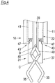
Im Bereich des Zangenkopfes 37 ist ein Stahldraht zu erkennen, der als Bowdenzugseele 39 dient und der optional mit einem dünnen Mantel aus Kunststoff versehen sein kann. Zwei Umlenkhebel 40, die mit den Backen 35 gelenkig gekoppelt sind, sind an dem Ende der Bowdenzugseele 39 befestigt und dort um eine gemeinsame Schwenkachse D gegenläufig schwenkbar gelagert. Durch Versetzen der Bowdenzugseele 39 relativ zu dem Zangenkopf 37 können somit die Backen 35 der Einwegbiopsiezange 31 wahlweise geöffnet oder geschlossen werden.In the region of the
Die Bowdenzugseele 39 ist bei dem hier gezeigten Ausführungsbeispiel in einer optionalen, schlauchartigen Einführröhre 41 angeordnet, welche insbesondere aus einem Kunststoffmaterial besteht. Die Einführröhre 41 erleichtert das Einführen der Einwegbiopsiezange 31 in den Arbeitskanal 22 des Einwegschlauchs 11 bis zu dem Erreichen der gezeigten Arbeitsposition.The
Am distalen Ende 14 des Einwegschlauchs 11 ist eine Befestigungseinrichtung 43 für den Zangenkopf 37 vorgesehen, um den Zangenkopf 37 in seiner Arbeitsposition am distalen Ende 14 des Einwegschlauchs 11 festzulegen. Dies geschieht bei dem hier gezeigten Ausführungsbeispiel durch einen lösbaren Rastschluss, d.h. durch eine lösbare Schnappverbindung. Die Befestigungseinrichtung 43 umfasst hierfür eine Rastvertiefung 45 am Zangenkopf 37, welche die Form einer umlaufenden Ringnut besitzt. In die Rastvertiefung 45 des Zangenkopfes 37 kann ein rückfedernd ausgebildeter Rastvorsprung 47 des Einwegschlauchs 11 einrasten, wenn sich die Einwegbiopsiezange 31 in der gezeigten Arbeitsposition befindet. Der Rastvorsprung 47 besitzt die Form eines radial nach innen ragenden umlaufenden Stegs.At the
Für das Konfigurieren des Einwegsystems 10 wird also ausgehend von dem proximalen Ende 16 des Einwegschlauchs 11 die Einwegbiopsiezange 31 mit dem Zangenkopf 37 voraus durch den Arbeitskanal 22 geführt, wobei diese Bewegung mittels der Einführröhre 41 unterstützt wird. Insbesondere kann die Einführröhre 41 dazu verwendet werden, den Zangenkopf 37 nach vorne bis in die genannte Arbeitsposition zu schieben. Der Einwegschlauch 11 kann sich hierbei bereits im Körper des Patienten befinden. Die Einführbewegung der Einwegbiopsiezange 31 wird solange durchgeführt, bis die Spitze der Einwegbiopsiezange 31 am distalen Ende 14 des Einwegschlauchs 11 aus dem Arbeitskanal 22 ausgefahren ist. Hierdurch wird die in
Nun kann zunächst die Einführröhre 41 entfernt werden. Anschließend kann am proximalen Ende des Einwegschlauchs 11 noch eine Betätigungseinrichtung angebracht werden, wie nachstehend noch erläutert wird. Nun kann mittels der Einwegbiopsiezange 31 eine gewünschte Probe entnommen werden, während gleichzeitig eine Beobachtung mittels des zugeordneten Endoskops erfolgen kann. Wird Kraft auf die Bowdenzugseele 39 ausgeübt, so schließen sich die Backen 35. Sobald eine Gewebeprobe oder dergleichen erfasst ist, kann die Einwegbiopsiezange 31 durch den Arbeitskanal 22 aus dem Körper des Patienten entnommen werden.Now, first, the
Durch Aufbringen einer vorbestimmten Zugkraft auf die Bowdenzugseele 39 kann der von der Befestigungseinrichtung 43 erzeugte Rastschluss wahlweise überwunden werden, so dass der Rastvorsprung 47 nicht mehr in Eingriff mit der Rastvertiefung 45 steht. Nach einem teilweisen oder vollständigen Zurückziehen der Einwegbiopsiezange 31 wird auch das Endoskop mitsamt Einwegsystem 10 aus dem Körper des Patienten zurückgezogen. Ist die Einwegbiopsiezange 31 mitsamt der Probe aus dem Arbeitskanal entnommen, kann alternativ eine neue Einwegbiopsiezange 31 in den Arbeitskanal eingeführt werden, beispielsweise um eine weitere Probe, insbesondere an einer anderen Stelle im Körper, zu entnehmen.By applying a predetermined tensile force on the
In
In
Zum Öffnen und Schließen der Backen 35 des Zangenkopfes 37 ist eine Betätigungseinrichtung 51 vorgesehen, welche in
Bei dem erfindungsgemäßen Einwegsystem 10 ist somit eine unerwünscht steife Ummantelung der Bowdenzugseele 39, beispielsweise aus Metall, nicht notwendig, wodurch die Flexibilität des Einwegsystems 10 deutlich erhöht wird. Durch die Verwendung von Einwegteilen wird auch die Hygiene bei einer Endoskopie deutlich verbessert.In the
- 1010
- Endoskopie- und Biopsie-EinwegsystemEndoscopy and biopsy disposable system
- 1111
- Einwegschlauchdisposable hose
- 1212
- Längsachse des EinwegschlauchsLongitudinal axis of the disposable tube
- 12'12 '
- Längsachse der Fixiermanschette und der FührungsschlaufenLongitudinal axis of the fixation cuff and the guide loops
- 1414
- distales Endedistal end
- 1616
- proximales Endeproximal end
- 1818
- Abdeckungcover
- 2020
- Austrittsöffnungoutlet opening
- 2222
- Arbeitskanalworking channel
- 2424
- Spülkanalirrigation channel
- 2626
- Fixiermanschettefixing cuff
- 2828
- Führungsschlaufeguide loop
- 3030
- Klebeverbindungadhesive bond
- 3131
- EinwegbiopsiezangeDisposable biopsy forceps
- 3232
- Verbindungsschlauchconnecting hose
- 3333
- Aufreißdornripper shank
- 3535
- Backejaw
- 3737
- Zangenkopfpliers head
- 3939
- BowdenzugseeleBowden cable
- 4040
- UmlenkhebelUmlenkhebel
- 4141
- Einführröhreinsertion tube
- 4343
- Befestigungseinrichtungfastening device
- 4545
- Rastvertiefunglatching depression
- 4747
- Rastvorsprungcatch projection
- 4949
- Klebemitteladhesive
- 5151
- Betätigungseinrichtungactuator
- 5353
- Gewindethread
- 5454
- Permanentmagnetpermanent magnet
- 54'54 '
- magnetisches Gegenelementmagnetic counter element
- 5555
- Antriebsabschnittdriving section
- 5757
- Gehäuseabschnitthousing section
- RR
- Betätigungsrichtungoperating direction
- CC
- Schwenkachseswivel axis
- DD
- Schwenkachseswivel axis
Claims (14)
- A disposable endoscopy and biopsy system (10) comprising:a disposable tube (11) which surrounds at least one working passage (22) and which has endoscope fastening means (26, 28) for fastening the disposable tube (11) to an endoscope; andat least one pair of disposable biopsy forceps (31) which can be introduced or is introduced into the working passage (22), wherein the pair of disposable biopsy forceps (31) has a forceps head (37) comprising at least two movable jaws (35) and a Bowden cable core (39) for actuating the jaws (35); andwherein a fastening device (43) is provided for temporarily or permanently fastening the forceps head (37) to a distal end (14) of the disposable tube (11) in a working position in which the jaws (35) of the forceps head (37) project beyond the distal end (14) of the disposable tube (11),characterized in thatthe fastening device (43) is provided at the forceps head (37) and/or at the distal end (14) of the disposable tube (11).
- A disposable system in accordance with claim 1,
wherein the fastening device (43) is adapted to fasten the forceps head (37) to the distal end (14) of the disposable tube (11) in an axially fixed, but rotationally movable manner in the working position. - A disposable system in accordance with one of the preceding claims,
wherein the fastening device (43) is adapted to establish a latching engagement between the distal end (14) of the disposable tube (11) and the forceps head (37) in said working position, and wherein at least one latch projection (47) is provided at the distal end (14) of the disposable tube (11) and at least one associated latch recess (45) is provided at the forceps head (37) or vice versa. - A disposable system in accordance with claim 3,
wherein the at least one latch projection (47) is an integral section of the disposable tube (11) or of the forceps head (37) which is preloaded in the direction of an engagement position due to inherent elasticity; or
wherein the at least one latch projection (47) is a separate element which is movably supported at the disposable tube (11) or at the forceps head (37) and which is preloaded in the direction of an engagement position by means of a preloading device. - A disposable system in accordance with one of the claims 1 or 2,
wherein the fastening device (43) is adapted to establish a magnetic coupling between the distal end of the disposable tube (11) and the forceps head (37) in said working position, and wherein at least one permanent magnet (54) is provided at the distal end (14) of the disposable tube (11) and at least one associated magnetic counter-element (54') is provided at the forceps head (37) or vice versa. - A disposable system in accordance with any one of the preceding claims,
wherein the fastening device (43) is adapted to release the forceps head (37) from the distal end (14) of the disposable tube (11) starting from said working position when the forceps head (37) is acted on by a predetermined force;
or
wherein the fastening device (43) has a materially continuous, shape-matched and/or force-transmitting combination means for permanently fastening the forceps head (37) to the distal end (14) of the disposable tube (11). - A disposable system in accordance with any one of the preceding claims,
wherein the disposable system furthermore has an introduction tube (41) which is adapted to be introduced into the working passage (22) together with the pair of disposable biopsy forceps (31), starting from a proximal end (16) of the disposable tube (11), in order to move the forceps head (37) into the working position, with the introduction tube (41) surrounding the Bowden cable core (39) in the introduced state, and with the introduction tube (41) being adapted to be removed to proximal from the working passage (22) while the forceps head (37) is in the working position; and
wherein the fastening device (43) is preferably adapted to fasten the forceps head (37) to the distal end (14) of the disposable tube (11) in an axially fixed, but rotationally movable manner in the working position, with the introduction tube (41) having an engagement means at a distal end which cooperates with an associated counter-engagement means at the forceps head (37) such that a rotational movement can be transmitted from the introduction tube (41) to the forceps head (37) which is fastened in the working position. - A disposable system in accordance with any one of the preceding claims,
wherein the disposable system furthermore has an actuation device (51) for displacing the Bowden cable core (39) relative to the disposable tube (11), with the actuation device (51) having at least one housing section (57) which is fastenable to a coupling device (53) at the proximal end (16) of the disposable tube (11), and with the actuation device (51) furthermore having at least one drive section (55) which is movably supported relative to the housing section (57) and which is fastenable to a proximal end of the Bowden cable core (39);
and/or
wherein the Bowden cable core (39) of the pair of disposable biopsy forceps (31) has a core composed of metal and a jacket composed of plastic. - A disposable system in accordance with any one of the preceding claims,
wherein the endoscope fastening means have a fixing device (26) by which the disposable tube (11) is rotationally fixedly and axially fixedly fixable to the distal end (14) of the endoscope, and wherein the endoscope fastening means furthermore have at least one guide device (28) by which the disposable tube (11) is displaceably fastenable to a respective section of the endoscope spaced apart from the distal end (14) of the endoscope;
and/or
wherein the disposable tube (11) additionally surrounds at least one flushing passage (24), with the disposable tube (11) having an outlet opening (20) of the flushing passage (24) at its distal end; and/or
wherein the disposable tube (11) has a cover (18) at its distal end (14) which seals the working passage (22) at the distal end (14) of the disposable tube (11) and which is configured to be opened by the application of force by means of the pair of disposable biopsy forceps (31) introduced into the working passage (22). - A method of configuring a disposable system in accordance with any one of the preceding claims, comprising the steps:introducing the pair of disposable biopsy forceps (31) into the working passage (22) of the disposable tube (11) from its proximal end (16) until the forceps head (37) reaches the distal end (14) of the disposable tube (11); andfastening the forceps head (37) to the distal end (14) of the disposable tube (11) in the working position.
- A method in accordance with claim 10,
wherein the disposable system has an introduction tube (41); wherein the introduction tube (41) surrounds the Bowden cable core (39) of the pair of disposable biopsy forceps (31) during the step of introducing the pair of disposable biopsy forceps (31) into the working passage (22) of the disposable tube (11); and
wherein the introduction tube (41) is removed to proximal from the working passage (22) after the step of introducing the pair of disposable biopsy forceps (31) into the working passage (22) of the disposable tube (11). - A method in accordance with claim 10 or claim 11,
wherein the disposable system has an actuation device (51) for displacing the Bowden cable core (39) relative to the disposable tube (11), with the actuation device (51) having at least one housing section (57) and at least one drive section (55) which is movably supported relative to the housing section (57),
said method comprising the additional steps which are carried out after the step of fastening the forceps head (37) in the working position:fastening the housing section (57) of the actuation device (51) to the proximal end (16) of the disposable tube (11); andfastening the drive section (55) of the actuation device (51) to the proximal end of the Bowden cable core (39). - A method in accordance with any one of the claims 10 to 12, wherein the disposable system comprises at least one further pair of disposable biopsy forceps which has a forceps head comprising at least two movable jaws and a Bowden cable core for actuating the jaws,
said method comprising the additional steps:releasing the forceps head (37) of said one pair of disposable biopsy forceps (31) from the distal end (14) of the disposable tube (11) and pulling said one pair of disposable biopsy forceps (31) out of the working passage (22) of the disposable tube (11);introducing said further pair of disposable biopsy forceps into the working passage (22) of the disposable tube (11) from its proximal end (16) until the forceps head of said further pair of disposable biopsy forceps reaches the distal end (14) of the disposable tube (11); andfastening the forceps head of said further pair of disposable biopsy forceps to the distal end (14) of the disposable tube (11) in the working position. - A method in accordance with claim 13,
wherein the disposable system has an introduction tube;
wherein the introduction tube surrounds the Bowden cable core of said further pair of disposable biopsy forceps during the step of introducing said further pair of disposable biopsy forceps into the working passage (22) of the disposable tube (11); and
wherein the introduction tube is removed to proximal from the working passage (22) after the step of introducing said further pair of disposable biopsy forceps into the working passage (22) of the disposable tube (11).
Applications Claiming Priority (2)
| Application Number | Priority Date | Filing Date | Title |
|---|---|---|---|
| DE102012219342.1A DE102012219342A1 (en) | 2012-10-23 | 2012-10-23 | Endoscopy and biopsy disposable system |
| PCT/EP2013/072072 WO2014064105A1 (en) | 2012-10-23 | 2013-10-22 | Disposable endoscopy and biopsy system |
Publications (2)
| Publication Number | Publication Date |
|---|---|
| EP2903494A1 EP2903494A1 (en) | 2015-08-12 |
| EP2903494B1 true EP2903494B1 (en) | 2019-01-09 |
Family
ID=49485713
Family Applications (1)
| Application Number | Title | Priority Date | Filing Date |
|---|---|---|---|
| EP13782688.9A Not-in-force EP2903494B1 (en) | 2012-10-23 | 2013-10-22 | Disposable endoscopy and biopsy system |
Country Status (3)
| Country | Link |
|---|---|
| EP (1) | EP2903494B1 (en) |
| DE (1) | DE102012219342A1 (en) |
| WO (1) | WO2014064105A1 (en) |
Families Citing this family (4)
| Publication number | Priority date | Publication date | Assignee | Title |
|---|---|---|---|---|
| CN113813017A (en) * | 2016-02-02 | 2021-12-21 | 奥林巴斯株式会社 | Endoscopic treatment instrument |
| CN106137271A (en) * | 2016-07-31 | 2016-11-23 | 上海市同济医院 | A kind of Detachable endoscope biopsy forceps |
| CN112932400A (en) * | 2021-01-27 | 2021-06-11 | 上海市第一人民医院 | Continuous expansion device for esophageal entrance stenosis |
| CN114224400B (en) * | 2021-12-14 | 2022-07-22 | 湖南朗开医疗科技有限公司 | Disposable quick biopsy forceps for bronchoscope |
Family Cites Families (7)
| Publication number | Priority date | Publication date | Assignee | Title |
|---|---|---|---|---|
| JP3688355B2 (en) * | 1995-08-03 | 2005-08-24 | 株式会社町田製作所 | Endoscopy forceps device |
| US6059719A (en) * | 1997-08-06 | 2000-05-09 | Olympus Optical Co., Ltd. | Endoscope system |
| US20060149131A1 (en) * | 2005-01-05 | 2006-07-06 | Sightline Technologies Ltd. | Surgical tool for endoscope |
| US8021293B2 (en) * | 2006-01-13 | 2011-09-20 | Olympus Medical Systems Corp. | Medical treatment endoscope |
| DE102007008099B4 (en) * | 2007-02-19 | 2021-05-20 | Ingoscope Systems Gmbh | Tube arrangement for an endoscope |
| US8088062B2 (en) * | 2007-06-28 | 2012-01-03 | Ethicon Endo-Surgery, Inc. | Interchangeable endoscopic end effectors |
| DE102010049568A1 (en) | 2009-10-27 | 2011-04-28 | Ingoscope Systems Gmbh | Hose assembly for use in endoscopy system for endoscope, particularly for flexible gastroscope, has disposable hose, which surrounds working channel for inserting working device |
-
2012
- 2012-10-23 DE DE102012219342.1A patent/DE102012219342A1/en not_active Withdrawn
-
2013
- 2013-10-22 EP EP13782688.9A patent/EP2903494B1/en not_active Not-in-force
- 2013-10-22 WO PCT/EP2013/072072 patent/WO2014064105A1/en active Application Filing
Non-Patent Citations (1)
| Title |
|---|
| None * |
Also Published As
| Publication number | Publication date |
|---|---|
| WO2014064105A1 (en) | 2014-05-01 |
| DE102012219342A1 (en) | 2014-04-24 |
| EP2903494A1 (en) | 2015-08-12 |
Similar Documents
| Publication | Publication Date | Title |
|---|---|---|
| EP2124706B1 (en) | Tube assembly for an endoscope | |
| EP2316351B1 (en) | Medical instrument for setting tissue clamps | |
| DE10126062B4 (en) | Hood for an endoscope | |
| DE19827468B4 (en) | Ligation device for an endoscope | |
| EP1673004B1 (en) | Endoscope comprising a flexible probe | |
| EP1713376A1 (en) | Endoscope comprising a flexible probe | |
| WO2000048506A1 (en) | Deformable fiberscope with a displaceable supplementary device | |
| DE3615694A1 (en) | Percutaneous nephroscope with safety wire | |
| EP1754438B1 (en) | Endoscope, in particular duodendoscope for mother-baby- cholangioscopy | |
| EP1610695A1 (en) | Surgical instrument system | |
| DE602004012173T2 (en) | Wire basket forceps | |
| EP2903494B1 (en) | Disposable endoscopy and biopsy system | |
| EP1083834B1 (en) | Device for producing a transcutaneous access to a hollow viscus in the interior of the body | |
| EP3968836B1 (en) | Tissue clip application fitting or retrofitting set | |
| EP2340759A1 (en) | Endoscopic instrument | |
| DE10045036C1 (en) | Therapeutic endoscope, for use at gall bladder, has a setting unit through a longitudinal guide channel, which can manipulate the bending end which carries the probe | |
| DE102009014178A1 (en) | Endoscope system has endoscope with insertion part inserted into human body opening, where operating unit is equipped for operating endoscope | |
| EP3155973B1 (en) | Biopsy forceps | |
| DE102009031209B4 (en) | Device for the endoscopic removal of stones or concrements from a biliary or pancreatic duct or of foreign bodies and polyps after polypectomy in the upper or lower gastrointestinal tract | |
| DE10241946A1 (en) | Apparatus for minimally invasive surgical removal of foreign bodies having a tube with a lumen open at the distal end | |
| DE102010049568A1 (en) | Hose assembly for use in endoscopy system for endoscope, particularly for flexible gastroscope, has disposable hose, which surrounds working channel for inserting working device | |
| DE69837853T2 (en) | ALIGNMENTAL ENDOSCOPIC SURGICAL DEVICE | |
| DE102015103913A1 (en) | Hollow shaft instrument and in particular medical endoscopic hollow shaft instrument | |
| DE102021208391A1 (en) | medical instrument | |
| DE102019130081A1 (en) | Tunneling device |
Legal Events
| Date | Code | Title | Description |
|---|---|---|---|
| PUAI | Public reference made under article 153(3) epc to a published international application that has entered the european phase |
Free format text: ORIGINAL CODE: 0009012 |
|
| 17P | Request for examination filed |
Effective date: 20150507 |
|
| AK | Designated contracting states |
Kind code of ref document: A1 Designated state(s): AL AT BE BG CH CY CZ DE DK EE ES FI FR GB GR HR HU IE IS IT LI LT LU LV MC MK MT NL NO PL PT RO RS SE SI SK SM TR |
|
| AX | Request for extension of the european patent |
Extension state: BA ME |
|
| DAX | Request for extension of the european patent (deleted) | ||
| STAA | Information on the status of an ep patent application or granted ep patent |
Free format text: STATUS: EXAMINATION IS IN PROGRESS |
|
| 17Q | First examination report despatched |
Effective date: 20170919 |
|
| REG | Reference to a national code |
Ref country code: DE Ref legal event code: R079 Ref document number: 502013012028 Country of ref document: DE Free format text: PREVIOUS MAIN CLASS: A61B0001273000 Ipc: A61B0010040000 |
|
| GRAP | Despatch of communication of intention to grant a patent |
Free format text: ORIGINAL CODE: EPIDOSNIGR1 |
|
| STAA | Information on the status of an ep patent application or granted ep patent |
Free format text: STATUS: GRANT OF PATENT IS INTENDED |
|
| RIC1 | Information provided on ipc code assigned before grant |
Ipc: A61B 1/00 20060101ALI20180626BHEP Ipc: A61B 1/018 20060101ALI20180626BHEP Ipc: A61B 10/04 20060101AFI20180626BHEP Ipc: A61B 1/273 20060101ALI20180626BHEP Ipc: A61B 10/06 20060101ALI20180626BHEP |
|
| INTG | Intention to grant announced |
Effective date: 20180719 |
|
| GRAS | Grant fee paid |
Free format text: ORIGINAL CODE: EPIDOSNIGR3 |
|
| GRAA | (expected) grant |
Free format text: ORIGINAL CODE: 0009210 |
|
| STAA | Information on the status of an ep patent application or granted ep patent |
Free format text: STATUS: THE PATENT HAS BEEN GRANTED |
|
| AK | Designated contracting states |
Kind code of ref document: B1 Designated state(s): AL AT BE BG CH CY CZ DE DK EE ES FI FR GB GR HR HU IE IS IT LI LT LU LV MC MK MT NL NO PL PT RO RS SE SI SK SM TR |
|
| REG | Reference to a national code |
Ref country code: GB Ref legal event code: FG4D Free format text: NOT ENGLISH |
|
| REG | Reference to a national code |
Ref country code: CH Ref legal event code: EP Ref country code: AT Ref legal event code: REF Ref document number: 1086331 Country of ref document: AT Kind code of ref document: T Effective date: 20190115 |
|
| REG | Reference to a national code |
Ref country code: DE Ref legal event code: R096 Ref document number: 502013012028 Country of ref document: DE |
|
| REG | Reference to a national code |
Ref country code: IE Ref legal event code: FG4D Free format text: LANGUAGE OF EP DOCUMENT: GERMAN |
|
| REG | Reference to a national code |
Ref country code: NL Ref legal event code: MP Effective date: 20190109 |
|
| REG | Reference to a national code |
Ref country code: LT Ref legal event code: MG4D |
|
| PG25 | Lapsed in a contracting state [announced via postgrant information from national office to epo] |
Ref country code: NL Free format text: LAPSE BECAUSE OF FAILURE TO SUBMIT A TRANSLATION OF THE DESCRIPTION OR TO PAY THE FEE WITHIN THE PRESCRIBED TIME-LIMIT Effective date: 20190109 |
|
| PG25 | Lapsed in a contracting state [announced via postgrant information from national office to epo] |
Ref country code: SE Free format text: LAPSE BECAUSE OF FAILURE TO SUBMIT A TRANSLATION OF THE DESCRIPTION OR TO PAY THE FEE WITHIN THE PRESCRIBED TIME-LIMIT Effective date: 20190109 Ref country code: PT Free format text: LAPSE BECAUSE OF FAILURE TO SUBMIT A TRANSLATION OF THE DESCRIPTION OR TO PAY THE FEE WITHIN THE PRESCRIBED TIME-LIMIT Effective date: 20190509 Ref country code: FI Free format text: LAPSE BECAUSE OF FAILURE TO SUBMIT A TRANSLATION OF THE DESCRIPTION OR TO PAY THE FEE WITHIN THE PRESCRIBED TIME-LIMIT Effective date: 20190109 Ref country code: NO Free format text: LAPSE BECAUSE OF FAILURE TO SUBMIT A TRANSLATION OF THE DESCRIPTION OR TO PAY THE FEE WITHIN THE PRESCRIBED TIME-LIMIT Effective date: 20190409 Ref country code: PL Free format text: LAPSE BECAUSE OF FAILURE TO SUBMIT A TRANSLATION OF THE DESCRIPTION OR TO PAY THE FEE WITHIN THE PRESCRIBED TIME-LIMIT Effective date: 20190109 Ref country code: ES Free format text: LAPSE BECAUSE OF FAILURE TO SUBMIT A TRANSLATION OF THE DESCRIPTION OR TO PAY THE FEE WITHIN THE PRESCRIBED TIME-LIMIT Effective date: 20190109 Ref country code: LT Free format text: LAPSE BECAUSE OF FAILURE TO SUBMIT A TRANSLATION OF THE DESCRIPTION OR TO PAY THE FEE WITHIN THE PRESCRIBED TIME-LIMIT Effective date: 20190109 |
|
| PG25 | Lapsed in a contracting state [announced via postgrant information from national office to epo] |
Ref country code: IS Free format text: LAPSE BECAUSE OF FAILURE TO SUBMIT A TRANSLATION OF THE DESCRIPTION OR TO PAY THE FEE WITHIN THE PRESCRIBED TIME-LIMIT Effective date: 20190509 Ref country code: HR Free format text: LAPSE BECAUSE OF FAILURE TO SUBMIT A TRANSLATION OF THE DESCRIPTION OR TO PAY THE FEE WITHIN THE PRESCRIBED TIME-LIMIT Effective date: 20190109 Ref country code: LV Free format text: LAPSE BECAUSE OF FAILURE TO SUBMIT A TRANSLATION OF THE DESCRIPTION OR TO PAY THE FEE WITHIN THE PRESCRIBED TIME-LIMIT Effective date: 20190109 Ref country code: GR Free format text: LAPSE BECAUSE OF FAILURE TO SUBMIT A TRANSLATION OF THE DESCRIPTION OR TO PAY THE FEE WITHIN THE PRESCRIBED TIME-LIMIT Effective date: 20190410 Ref country code: BG Free format text: LAPSE BECAUSE OF FAILURE TO SUBMIT A TRANSLATION OF THE DESCRIPTION OR TO PAY THE FEE WITHIN THE PRESCRIBED TIME-LIMIT Effective date: 20190409 Ref country code: RS Free format text: LAPSE BECAUSE OF FAILURE TO SUBMIT A TRANSLATION OF THE DESCRIPTION OR TO PAY THE FEE WITHIN THE PRESCRIBED TIME-LIMIT Effective date: 20190109 |
|
| REG | Reference to a national code |
Ref country code: DE Ref legal event code: R097 Ref document number: 502013012028 Country of ref document: DE |
|
| PG25 | Lapsed in a contracting state [announced via postgrant information from national office to epo] |
Ref country code: CZ Free format text: LAPSE BECAUSE OF FAILURE TO SUBMIT A TRANSLATION OF THE DESCRIPTION OR TO PAY THE FEE WITHIN THE PRESCRIBED TIME-LIMIT Effective date: 20190109 Ref country code: RO Free format text: LAPSE BECAUSE OF FAILURE TO SUBMIT A TRANSLATION OF THE DESCRIPTION OR TO PAY THE FEE WITHIN THE PRESCRIBED TIME-LIMIT Effective date: 20190109 Ref country code: IT Free format text: LAPSE BECAUSE OF FAILURE TO SUBMIT A TRANSLATION OF THE DESCRIPTION OR TO PAY THE FEE WITHIN THE PRESCRIBED TIME-LIMIT Effective date: 20190109 Ref country code: EE Free format text: LAPSE BECAUSE OF FAILURE TO SUBMIT A TRANSLATION OF THE DESCRIPTION OR TO PAY THE FEE WITHIN THE PRESCRIBED TIME-LIMIT Effective date: 20190109 Ref country code: DK Free format text: LAPSE BECAUSE OF FAILURE TO SUBMIT A TRANSLATION OF THE DESCRIPTION OR TO PAY THE FEE WITHIN THE PRESCRIBED TIME-LIMIT Effective date: 20190109 Ref country code: SK Free format text: LAPSE BECAUSE OF FAILURE TO SUBMIT A TRANSLATION OF THE DESCRIPTION OR TO PAY THE FEE WITHIN THE PRESCRIBED TIME-LIMIT Effective date: 20190109 Ref country code: AL Free format text: LAPSE BECAUSE OF FAILURE TO SUBMIT A TRANSLATION OF THE DESCRIPTION OR TO PAY THE FEE WITHIN THE PRESCRIBED TIME-LIMIT Effective date: 20190109 |
|
| PLBE | No opposition filed within time limit |
Free format text: ORIGINAL CODE: 0009261 |
|
| STAA | Information on the status of an ep patent application or granted ep patent |
Free format text: STATUS: NO OPPOSITION FILED WITHIN TIME LIMIT |
|
| PG25 | Lapsed in a contracting state [announced via postgrant information from national office to epo] |
Ref country code: SM Free format text: LAPSE BECAUSE OF FAILURE TO SUBMIT A TRANSLATION OF THE DESCRIPTION OR TO PAY THE FEE WITHIN THE PRESCRIBED TIME-LIMIT Effective date: 20190109 |
|
| 26N | No opposition filed |
Effective date: 20191010 |
|
| PG25 | Lapsed in a contracting state [announced via postgrant information from national office to epo] |
Ref country code: SI Free format text: LAPSE BECAUSE OF FAILURE TO SUBMIT A TRANSLATION OF THE DESCRIPTION OR TO PAY THE FEE WITHIN THE PRESCRIBED TIME-LIMIT Effective date: 20190109 |
|
| PGFP | Annual fee paid to national office [announced via postgrant information from national office to epo] |
Ref country code: FR Payment date: 20191030 Year of fee payment: 7 |
|
| PG25 | Lapsed in a contracting state [announced via postgrant information from national office to epo] |
Ref country code: TR Free format text: LAPSE BECAUSE OF FAILURE TO SUBMIT A TRANSLATION OF THE DESCRIPTION OR TO PAY THE FEE WITHIN THE PRESCRIBED TIME-LIMIT Effective date: 20190109 |
|
| REG | Reference to a national code |
Ref country code: DE Ref legal event code: R119 Ref document number: 502013012028 Country of ref document: DE |
|
| PG25 | Lapsed in a contracting state [announced via postgrant information from national office to epo] |
Ref country code: MC Free format text: LAPSE BECAUSE OF FAILURE TO SUBMIT A TRANSLATION OF THE DESCRIPTION OR TO PAY THE FEE WITHIN THE PRESCRIBED TIME-LIMIT Effective date: 20190109 |
|
| REG | Reference to a national code |
Ref country code: CH Ref legal event code: PL |
|
| PG25 | Lapsed in a contracting state [announced via postgrant information from national office to epo] |
Ref country code: DE Free format text: LAPSE BECAUSE OF NON-PAYMENT OF DUE FEES Effective date: 20200501 Ref country code: LI Free format text: LAPSE BECAUSE OF NON-PAYMENT OF DUE FEES Effective date: 20191031 Ref country code: LU Free format text: LAPSE BECAUSE OF NON-PAYMENT OF DUE FEES Effective date: 20191022 Ref country code: CH Free format text: LAPSE BECAUSE OF NON-PAYMENT OF DUE FEES Effective date: 20191031 |
|
| REG | Reference to a national code |
Ref country code: BE Ref legal event code: MM Effective date: 20191031 |
|
| PG25 | Lapsed in a contracting state [announced via postgrant information from national office to epo] |
Ref country code: BE Free format text: LAPSE BECAUSE OF NON-PAYMENT OF DUE FEES Effective date: 20191031 |
|
| GBPC | Gb: european patent ceased through non-payment of renewal fee |
Effective date: 20191022 |
|
| PG25 | Lapsed in a contracting state [announced via postgrant information from national office to epo] |
Ref country code: GB Free format text: LAPSE BECAUSE OF NON-PAYMENT OF DUE FEES Effective date: 20191022 Ref country code: IE Free format text: LAPSE BECAUSE OF NON-PAYMENT OF DUE FEES Effective date: 20191022 |
|
| REG | Reference to a national code |
Ref country code: AT Ref legal event code: MM01 Ref document number: 1086331 Country of ref document: AT Kind code of ref document: T Effective date: 20191022 |
|
| PG25 | Lapsed in a contracting state [announced via postgrant information from national office to epo] |
Ref country code: AT Free format text: LAPSE BECAUSE OF NON-PAYMENT OF DUE FEES Effective date: 20191022 |
|
| PG25 | Lapsed in a contracting state [announced via postgrant information from national office to epo] |
Ref country code: CY Free format text: LAPSE BECAUSE OF FAILURE TO SUBMIT A TRANSLATION OF THE DESCRIPTION OR TO PAY THE FEE WITHIN THE PRESCRIBED TIME-LIMIT Effective date: 20190109 |
|
| PG25 | Lapsed in a contracting state [announced via postgrant information from national office to epo] |
Ref country code: HU Free format text: LAPSE BECAUSE OF FAILURE TO SUBMIT A TRANSLATION OF THE DESCRIPTION OR TO PAY THE FEE WITHIN THE PRESCRIBED TIME-LIMIT; INVALID AB INITIO Effective date: 20131022 Ref country code: MT Free format text: LAPSE BECAUSE OF FAILURE TO SUBMIT A TRANSLATION OF THE DESCRIPTION OR TO PAY THE FEE WITHIN THE PRESCRIBED TIME-LIMIT Effective date: 20190109 Ref country code: FR Free format text: LAPSE BECAUSE OF NON-PAYMENT OF DUE FEES Effective date: 20201031 |
|
| PG25 | Lapsed in a contracting state [announced via postgrant information from national office to epo] |
Ref country code: MK Free format text: LAPSE BECAUSE OF FAILURE TO SUBMIT A TRANSLATION OF THE DESCRIPTION OR TO PAY THE FEE WITHIN THE PRESCRIBED TIME-LIMIT Effective date: 20190109 |