EP3155973B1 - Biopsy forceps - Google Patents
Biopsy forceps Download PDFInfo
- Publication number
- EP3155973B1 EP3155973B1 EP16192977.3A EP16192977A EP3155973B1 EP 3155973 B1 EP3155973 B1 EP 3155973B1 EP 16192977 A EP16192977 A EP 16192977A EP 3155973 B1 EP3155973 B1 EP 3155973B1
- Authority
- EP
- European Patent Office
- Prior art keywords
- biopsy forceps
- guide
- pull
- forceps
- distal
- Prior art date
- Legal status (The legal status is an assumption and is not a legal conclusion. Google has not performed a legal analysis and makes no representation as to the accuracy of the status listed.)
- Not-in-force
Links
Images


Classifications
-
- A—HUMAN NECESSITIES
- A61—MEDICAL OR VETERINARY SCIENCE; HYGIENE
- A61B—DIAGNOSIS; SURGERY; IDENTIFICATION
- A61B10/00—Other methods or instruments for diagnosis, e.g. instruments for taking a cell sample, for biopsy, for vaccination diagnosis; Sex determination; Ovulation-period determination; Throat striking implements
- A61B10/02—Instruments for taking cell samples or for biopsy
- A61B10/04—Endoscopic instruments
-
- A—HUMAN NECESSITIES
- A61—MEDICAL OR VETERINARY SCIENCE; HYGIENE
- A61B—DIAGNOSIS; SURGERY; IDENTIFICATION
- A61B10/00—Other methods or instruments for diagnosis, e.g. instruments for taking a cell sample, for biopsy, for vaccination diagnosis; Sex determination; Ovulation-period determination; Throat striking implements
- A61B10/02—Instruments for taking cell samples or for biopsy
- A61B10/06—Biopsy forceps, e.g. with cup-shaped jaws
-
- A—HUMAN NECESSITIES
- A61—MEDICAL OR VETERINARY SCIENCE; HYGIENE
- A61B—DIAGNOSIS; SURGERY; IDENTIFICATION
- A61B90/00—Instruments, implements or accessories specially adapted for surgery or diagnosis and not covered by any of the groups A61B1/00 - A61B50/00, e.g. for luxation treatment or for protecting wound edges
- A61B90/03—Automatic limiting or abutting means, e.g. for safety
- A61B2090/033—Abutting means, stops, e.g. abutting on tissue or skin
- A61B2090/034—Abutting means, stops, e.g. abutting on tissue or skin abutting on parts of the device itself
-
- A—HUMAN NECESSITIES
- A61—MEDICAL OR VETERINARY SCIENCE; HYGIENE
- A61B—DIAGNOSIS; SURGERY; IDENTIFICATION
- A61B90/00—Instruments, implements or accessories specially adapted for surgery or diagnosis and not covered by any of the groups A61B1/00 - A61B50/00, e.g. for luxation treatment or for protecting wound edges
- A61B90/06—Measuring instruments not otherwise provided for
- A61B2090/062—Measuring instruments not otherwise provided for penetration depth
Description
Die vorliegende Erfindung betrifft eine Biopsiezange, die insbesondere als Punktionsbiopsiezange ausgebildet sein kann. Bei einer gattungsgemäßen Biopsiezange handelt es sich um endoskopisches Zubehör. Sie umfasst ein längliches Zug-/Schubteil, an dessen distalem Längsende ein Zangenkopf angebracht ist und an dessen proximalem Ende sich eine Handhabungseinrichtung befindet, mittels welcher von einem Operateur der Zangenkopf bedarfsweise geöffnet und geschlossen werden kann. Die Biopsiezange kann mit zunächst geschlossenem Zangenkopf durch einen Arbeitskanal eines in einen menschlichen oder tierischen Körper eingeführten Endoskops geführt werden, so dass ihr distales Längsende über die Endoskopspitze hinausragt, wobei sich die Handhabungseinrichtung außerhalb des proximalen Endoskopendes und außerhalb des menschlichen bzw. tierischen Körpers befindet. Bei dieser Anordnung kann das aus den beiden Branchen des Zangenkopfs gebildete Zangenmaul mittels der Handhabungseinrichtung geöffnet werden, mittels den Branchen Gewebe ergriffen, die Branchen anschließend wieder zusammengedrückt und zwischen ihnen festgeklemmtes Gewebe abgezupft werden, um dieses, bspw. für Untersuchungen, aus dem Körper zu entfernen.The present invention relates to a biopsy forceps, which may be designed in particular as puncture biopsy forceps. A generic biopsy forceps are endoscopic accessories. It comprises an elongate pulling / pushing part, at the distal longitudinal end of which a pliers head is attached and at the proximal end of which a handling device is located, by means of which the pliers head can be opened and closed as required by an operator. The biopsy forceps can be performed with initially closed forceps head through a working channel of an inserted into a human or animal body endoscope so that its distal longitudinal end protrudes beyond the endoscope tip, wherein the handling device is outside the proximal Endoskopendes and outside the human or animal body. In this arrangement, the pliers mouth formed from the two branches of the pliers head can be opened by means of the handling device, grabbed by the branches tissue, the industries then compressed again and plucked between them tissue to this, for example, for examinations, from the body remove.
Gemäß dem Oberbegriff von Anspruch 1 betrifft die vorliegende Erfindung eine Biopsiezange, insbesondere Punktionsbiopsiezange, wobei die Biopsiezange einen Zangenkopf umfasst, wobei die Biopsiezange ein erstes Zug-/Schubteil umfasst, an dessen distalem Längsende der Zangenkopf angebracht ist, wobei die Biopsiezange eine flexible Ummantelung umfasst, die einen Hohlkanal aufweist, durch den das erste Zug-/Schubteil relativ zu der flexiblen Ummantelung längsverschieblich hindurchgeführt ist, wobei die Biopsiezange eine Handhabungseinrichtung umfasst, die eine Halteeinrichtung und eine erste Betätigungseinrichtung aufweist, wobei die Halteeinrichtung und die erste Betätigungseinrichtung gemeinsam eine erste Längsführung bilden, mittels der die erste Betätigungseinrichtung an der Halteeinrichtung relativ zu ihr entlang einer Betätigungsrichtung verschiebbar geführt ist, wobei die flexible Ummantelung, insbesondere an ihrem proximalen Längsende, mit der Halteeinrichtung verbunden ist, wobei das erste Zug-/Schubteil, insbesondere an seinem proximalen Längsende, mit der ersten Betätigungseinrichtung verbunden ist, wobei die Biopsiezange eine Wegbegrenzungseinrichtung umfasst, die an der ersten Längsführung an in Bezug auf die genannte Betätigungsrichtung wählbaren Positionen lösbar befestigbar ist und die in befestigtem Zustand einen Anschlag bildet, der einen Verschiebeweg der ersten Betätigungseinrichtung relativ zu der Halteeinrichtung in distaler Richtung begrenzt, wobei die Halteeinrichtung einen Führungskern aufweist, wobei die erste Betätigungsrichtung eine Führungshülse aufweist, wobei der Führungskern und die Führungshülse gemeinsam die erste Längsführung ausbilden, wobei die Wegbegrenzungseinrichtung eine Hülse aufweist, die auf den Führungskern aufgeschoben ist, wobei die Hülse in ihrer Wandung eine Gewindebohrung aufweist, in die eine Klemmschraube eingeschraubt ist, wobei die Hülse bei gelöster Klemmschraube auf dem Führungskern verschiebbar ist und wobei die Hülse bei festgezogener Klemmschraube an dem Führungskern fixiert ist.According to the preamble of
Im Stand der Technik sind Biopsiezangen bekannt, bei denen ein Zug-/Schubteil, an dessen distalem Längsende der Zangenkopf gehalten ist, in einem biegsamen Metallmantel längsverschieblich geführt ist. Während des Einführens in den Arbeitskanal des Endoskops ist der Zangenkopf in den Metallmantel zurückgezogen und darin geschützt. Wenn der Metallmantel aus dem Arbeitskanal nach distal hervortritt, wird das Zug-/Schubteil mittels der Handhabungseinrichtung nach distal aus dem Metallmantel hinausgeschoben, um zu dem relevanten Gewebe vorzudringen. Bei sog. Punktionsbiopsiezangen ist der Zangenkopf an seinem freien Längsende verjüngt ausgeführt, so dass er beim Hinausschieben in Körpergewebe eindringen kann. Bei herkömmlichen Biopsiezangen werden jedoch die bisher nur begrenzten Möglichkeiten zur Bewegung des Zangenkopfes mittels der Handhabungseinrichtung als Einschränkung empfunden. Des Weiteren bieten bekannte Punktionsbiopsiezangen nur eine als zu gering empfundene Punktionstiefe von maximal 2 cm.In the prior art biopsy forceps are known in which a pull / push part, is held at the distal longitudinal end of the pliers head, longitudinally displaceably guided in a flexible metal shell. During insertion into the working channel of the endoscope, the pliers head is retracted into the metal shell and protected therein. When the metal sheath emerges from the working channel to the distal, the pull / push part by means of Handling device pushed out distally from the metal shell to penetrate to the relevant tissue. In so-called puncture biopsy forceps, the forceps head is tapered at its free longitudinal end, so that it can penetrate body tissue when it is pushed out. In conventional biopsy forceps, however, the previously limited possibilities for moving the pliers head by means of the handling device are perceived as a limitation. Furthermore, known puncture biopsy forceps offer only a puncture depth of no more than 2 cm, which is perceived as being too low.
Aus
Aus
Vor diesem Hintergrund liegt der Erfindung die Aufgabe zugrunde, eine Biopsiezange, insbesondere eine Punktionsbiopsiezange, vorteilhaft weiterzubilden. Insbesondere wird angestrebt, dass mittels der Weiterbildung die aus dem Stand der Technik bekannten Einschränkungen möglichst weitgehend vermieden werden können. Insbesondere wird eine verbesserte Handhabbarkeit des Zangenkopfes angestrebt. Insbesondere wird auch eine im Vergleich zu dem Stand der Technik größere mögliche Punktionstiefe angestrebt.Against this background, the invention has the object, a biopsy forceps, in particular a puncture biopsy forceps, advantageously further. In particular, it is desirable that by means of further development the limitations known from the prior art can be avoided as far as possible. In particular, an improved handling of the pliers head is desired. In particular, a greater possible puncture depth compared to the prior art is desired.
Zur Lösung der gestellten Aufgabe schlägt die Erfindung gemäß Anspruch 1 vor, dass auf dem Führungskern mehrere in Betätigungsrichtung voneinander beabstandete Markierungen, insbesondere Zahlen, angebracht sind, wobei vorgesehen ist, dass die Hülse eine Ausnehmung aufweist, durch welche Markierungen ablesbar sind.To achieve the object, the invention proposes according to
Der besagte Anschlag bildet bei der Anwendung der Biopsiezange einen Tiefenanschlag, durch dessen Gebrauch erreicht werden kann, dass der Vorschub des Zangenkopfes im Körpergewebe nur bis zu einer bestimmten wählbaren Tiefe erfolgt. Dies verbessert die Handhabung des Zangenkopfes. Der Tiefenanschlag wiederum erlaubt einen im Vergleich zum Stand der Technik größeren möglichen Verschiebeweg des Zangenkopfes relativ zu der flexiblen Ummantelung, um auch größere Punktionstiefen zu realisieren. Der Tiefenanschlag kann dabei verhindern, dass bei einer nur gewünschten geringeren als der maximalen Punktionstiefe versehentlich ein zu großer, mit der Gefahr von erheblichen Verletzungen verbundener Vorschub erfolgt. Wie noch nachfolgend beschrieben wird, kann eine erfindungsgemäße Biopsiezange vorzugsweise als Punktionsbiopsiezange ausgeführt sein, indem sich ihr Zangenkopf zu seinem distalen Längsende hin verjüngt. Eine erfindungsgemäße Punktionsbiopsiezange kann zum Beispiel zur Entnahme von Gewebe aus der Pankreaszystenwand und aus Lymphknoten Anwendung finden. Die Arbeitslänge bzw. Gesamtlänge einer erfindungsgemäßen Biopsiezange kann bis zu mehreren Metern (bspw. 5 bis 6 m) betragen.The said stop forms when using the biopsy forceps a depth stop, through the use of which it can be achieved that the advancement of the forceps head in the body tissue only up to a certain selectable depth. This improves the handling of the pliers head. The depth stop in turn allows a larger possible displacement path of the pliers head relative to the prior art relative to the flexible sheath to realize even greater puncture depths. The depth stop can prevent that at an only desired lower than the maximum puncture depth inadvertently takes place an excessive, associated with the risk of serious injury feed. As will be described below, a biopsy forceps according to the invention may preferably be designed as a puncture biopsy forceps, with its forceps head tapering towards its distal longitudinal end. A puncture biopsy forceps according to the invention can be used, for example, for removing tissue from the pancreatic cyst wall and from lymph nodes. The working length or overall length of a biopsy forceps according to the invention can be up to several meters (for example 5 to 6 m).
Bei dem ersten Zug-/Schubteil handelt es sich um ein langgestrecktes Teil, das zu wahlweisen Übertragung von Zug- oder Schubkräften geeignet ist. Wenn die erste Betätigungseinrichtung in proximaler Richtung bewegt wird, kann mittels des ersten Zug-/Schubteils an dessen distalem Längsende eine Zugkraft übertragen werden. Wird hingegen die erste Betätigungseinrichtung in distaler Richtung bewegt, kann mittels des ersten Zug-/Schubteils an dessen distalem Längsende eine Schubkraft übertragen werden, mittels der sich der Zangenkopf in distaler Richtung bewegen lässt.The first pulling / pushing part is an elongated part suitable for selective transmission of pulling or pushing forces. When the first actuating device is moved in the proximal direction, a pulling force can be transmitted by means of the first pulling / pushing part at its distal longitudinal end. If, however, the first actuating device is moved in the distal direction, a thrust force can be transmitted by means of the first pulling / pushing part at its distal longitudinal end, by means of which the forceps head can be moved in the distal direction.
Es bestehen zahlreiche Möglichkeiten zur bevorzugten Weiterbildung einer erfindungsgemäßen Biopsiezange:
Es besteht die Möglichkeit, dass der Zangenkopf zwei Branchen aufweist, wobei eine Branche oder beide Branchen zwischen einer Geschlossenstellung und einer Offenstellung bewegbar ist oder sind. Vorzugsweise weist jede Branche eine löffelartige Ausnehmung auf. Anstelle von einer Hülse, die bei gelöster Klemmschraube auf dem Führungskern verschiebbar ist und die bei festgezogener Klemmschraube an dem Führungskern fixiert ist, könnte man insofern auch von einem Sicherheitsring sprechen. Bevorzugt ist, dass, wenn sich die erste Betätigungseinrichtung relativ zu der Halteeinrichtung in einer von einem proximalen Anschlag bestimmten proximalen Endposition befindet, der Zangenkopf in der flexiblen Ummantelung aufgenommen ist, und dass, wenn sich die Hülse und die erste Betätigungseinrichtung relativ zu der Halteeinrichtung in einer von einem distalen Anschlag der Halteeinrichtung bestimmten distalen Endposition befinden, der Zangenkopf und ein daran proximal angrenzender Längenteilabschnitt des ersten Zug-/Schubteils distal aus dem distalen Längsende der flexiblen Ummantelung hervorstehen. Zum Beispiel kann die distale Spitze des Zangenkopfes in der besagten Endposition um mindestens 5 cm, weiter vorzugsweise um zumindest 8 cm, aus der flexiblen Ummantelung hervorstehen.There are numerous possibilities for the preferred development of a biopsy forceps according to the invention:
There is the possibility that the pliers head has two branches, with one branch or both branches being or being movable between a closed position and an open position. Preferably, each industry has a spoon-like recess. Instead of a sleeve which is displaceable with the clamping screw loosened on the guide core and which is fixed at tightened clamping screw on the guide core, one could speak so far of a safety ring. It is preferred that, when the first actuator relative to the holding device in one of a proximal Stop is located at certain proximal end position, the pliers head is received in the flexible sheath, and that, when the sleeve and the first actuator relative to the holding device in a distal end of a stop of the holding device located distal end position, the pliers head and a proximally adjacent thereto Longitudinal portion of the first pull / push part projecting distally from the distal longitudinal end of the flexible sheath. For example, the distal tip of the forceps head may protrude from the flexible sheath in the end position by at least 5 cm, more preferably by at least 8 cm.
Bei einem bevorzugten Ausführungsbeispiel ist vorgesehen, dass die Handhabungseinrichtung eine zweite Betätigungseinrichtung und ein Führungsteil, das mit der zweiten Betätigungseinrichtung eine zweite Längsführung bildet und das an der ersten Betätigungseinrichtung, insbesondere an ihrem proximalen Ende, befestigt oder ausgebildet ist, aufweist, dass die Biopsiezange ein zweites Zug-/Schubteil aufweist, das sich in seiner Längsrichtung verschieblich durch einen jeweiligen Hohlkanal der flexiblen Ummantelung, der Halteeinrichtung, der ersten Betätigungseinrichtung und des Führungsteils bis zu der zweiten Betätigungseinrichtung erstreckt, das an seinem proximalen Längsende an der zweiten Betätigungseinrichtung befestigt ist und das an seinem distalen Längsende mit den Branchen verbunden ist. Es kann sich um eine mittelbare oder um eine unmittelbare Verbindung handeln. Das zweite Zug-/Schubteil könnte man auch als Teil oder als Seele zur wahlweisen Zug- oder Schubübertragung bezeichnen. Wenn die zweite Betätigungseinrichtung in proximaler Richtung bewegt wird, kann mittels des zweiten Zug-/Schubteiles eine Zugkraft an dessen distalem Längsende übertragen werden. Wenn die zweite Betätigungseinrichtung entgegen in distaler Richtung bewegt wird, kann mittels des zweiten Zug-/Schubteils an dessen distalem Längsende eine in distaler Richtung wirkende Schubkraft ausgeübt werden.In a preferred embodiment, it is provided that the handling device has a second actuating device and a guide part, which forms a second longitudinal guide with the second actuating device and which is attached to the first actuating device, in particular at its proximal end, that the biopsy forceps a second pull / push member slidably extending in its longitudinal direction through a respective hollow channel of the flexible sheath, the holding means, the first actuator and the guide member to the second actuator, which is secured at its proximal longitudinal end to the second actuator and the connected at its distal longitudinal end with the branches. It can be an indirect or an immediate connection. The second pull / push part could also be referred to as part or as a soul for the optional tensile or shear transmission. When the second actuating device is moved in the proximal direction, a tensile force can be transmitted to its distal longitudinal end by means of the second pulling / pushing part. When the second actuating device is moved counter to in the distal direction, a thrust force acting in the distal direction can be exerted by means of the second pulling / pushing part at its distal longitudinal end.
Als zweckmäßig wird angesehen, dass das erste Zug-/Schubteil als biegsames Röhrchen, insbesondere als sog. Mikro-Röhrchen, ausgebildet ist oder zumindest ein Röhrchen umfasst, dass das zweite Zug-/Schubteil als Draht ausgebildet ist oder zumindest einen Draht umfasst und dass das zweite Zug-/Schubteil durch einen Hohlkanal des ersten Zug-/Schubteils in seiner Längsrichtung verschieblich hindurchgeführt ist. Das zweite Zug-/Schubteil kann bspw. auch mehrere, in Längsrichtung aneinandergefügte Drähte umfassen. Bevorzugt ist, dass der Draht in dem Röhrchen längsverschieblich geführt ist und dass das Röhrchen längsverschieblich in der flexiblen Ummantelung geführt ist.It is considered appropriate that the first pulling / pushing part is designed as a flexible tube, in particular as a so-called micro-tube, or at least comprises a tube, that the second pulling / pushing part is formed as a wire or at least comprises a wire and that the second pulling / pushing part is guided displaceably in its longitudinal direction through a hollow channel of the first pulling / pushing part. The second pull / push part may, for example, also comprise a plurality of wires joined together in the longitudinal direction. It is preferred that the wire is guided longitudinally displaceable in the tube and that the tube is guided longitudinally displaceable in the flexible sheath.
Es besteht die Möglichkeit, dass eine Branche oder dass beide Branchen an dem Zangenkopf drehbar an einem Gelenk gehalten sind, dass sich an jede drehbare Branche proximal ein Hebelstück anschließt, das an seinem proximalen Ende mit je einem Hebelteil gelenkig verbunden ist und dass jedes Hebelteil an seinem proximalen Ende mit dem distalen Längsende des zweiten Zug-/Schubteils verbunden ist. Alternativ besteht die Möglichkeit, dass nur eine der beiden Branchen an dem Zangenkopf drehbar ist, und dass die andere Branche unbeweglich ist.There is the possibility that an industry or that both sectors are rotatably held on the pliers head at a joint, that connects to each rotatable industry proximally a lever piece, which is hinged at its proximal end with one lever member and that each lever part its proximal end is connected to the distal longitudinal end of the second pulling / pushing part. Alternatively, there is the possibility that only one of the two branches is rotatable on the pliers head and that the other branch is immovable.
Bei einer zweckmäßigen Ausgestaltung ist vorgesehen, dass die erste Betätigungseinrichtung auf ihrer proximalen Seite mit dem als zweiter Führungsdorn ausgebildeten Führungsteil verbunden ist, dass die zweite Betätigungseinrichtung als Griffspule ausgebildet und in einer Betätigungsrichtung verschieblich auf den zweiten Führungsdorn aufgeschoben ist.In an expedient embodiment, it is provided that the first actuating device is connected on its proximal side to the guide part designed as a second guide mandrel, that the second actuating device is designed as a handle coil and slidably displaced in an actuating direction on the second guide pin.
Eine erfindungsgemäße Biopsiezange kann als Punktionsbiopsiezange ausgebildet sein. Dazu besteht zum Beispiel die Möglichkeit, dass eine erste Branche länger als die zweite Branche ist, so dass sie sich in der Geschlossenstellung distal weiter als die zweite Branche erstreckt, wobei insbesondere vorgesehen ist, dass die erste Branche an ihrem freiem Längsende zu einer Spitze verjüngt ist. Insbesondere in diesem Zusammenhang wird als zweckmäßig angesehen, dass die erste Branche seitlich eine Ausnehmung aufweist, die geometrisch an eine teilweise oder vollständige Aufnahme der zweiten Branche in der Geschlossenstellung angepasst ist. Bevorzugt ist vorgesehen, dass eine oder beide Branchen schwenkbar an dem Zangenkopf gehalten und mittels des zweiten Zug-/Schubteils relativ zu dem distalen Längsende des ersten Zug-/Schubteils bewegbar ist oder sind. Dementsprechend kann der Zangenkopf entweder ein- oder beidseitig öffnend und schließend ausgestaltet sein.A biopsy forceps according to the invention can be designed as a puncture biopsy forceps. For example, there is the possibility that a first industry is longer than the second industry, so they are in the closed position extends distally than the second branch, wherein it is provided in particular that the first industry is tapered at its free longitudinal end to a point. In particular, in this context, it is considered appropriate that the first industry has laterally a recess which is geometrically adapted to a partial or complete recording of the second industry in the closed position. It is preferably provided that one or both branches is pivotally held on the pliers head and is movable by means of the second pull / push part relative to the distal longitudinal end of the first pull / push part or are. Accordingly, the pliers head can be designed either one-sided or two-sided opening and closing.
Bevorzugt ist, dass die flexible Ummantelung aus Kunststoff, insbesondere aus Polyetheretherketon (PEEK) hergestellt ist. Dadurch kann im Vergleich zu herkömmlich bei endoskopischen Instrumenten bekannten metallischen Ummantelungen, die helixartig gewundene, aneinanderliegende Windungen besitzen, eine weniger steife Gestaltung erreicht werden. Zugleich kann eine für die Anforderung genügende Härte, Gleitfähigkeit und Verformbarkeit erzielt werden. Dabei wird unter einer flexiblen Ummantelung allgemein eine biegsame Ummantelung verstanden. Vorzugsweise sind auch das erste Zug-/Schubteil und das zweite Zug-/Schubteil jeweils biegsam bzw. flexibel ausgebildet.It is preferred that the flexible sheath is made of plastic, in particular of polyetheretherketone (PEEK). As a result, a less rigid design can be achieved in comparison with conventional metal sheaths known in endoscopic instruments, which have helically wound, contiguous turns. At the same time, a hardness, lubricity and deformability sufficient for the requirement can be achieved. In this case, a flexible sheath is generally understood to mean a flexible sheath. Preferably, the first pull / push part and the second pull / push part are each flexible or flexible.
Als zweckmäßig wird angesehen, dass die Handhabungseinrichtung an ihrem distalen Längsende einen Luer-Anschluss oder einen Luer-Lock-Anschluss zum Anschließen an einen Arbeitskanal eines Endoskops aufweist. Dies ermöglicht insbesondere einen abdichtenden Anschluss an einen Arbeitskanal.It is considered appropriate that the handling device has at its distal longitudinal end a luer connection or a luer lock connection for connection to a working channel of an endoscope. This allows in particular a sealing connection to a working channel.
Die Erfindung wird nachfolgend mit Bezug auf die beigefügten Figuren, welche bevorzugte Ausführungsbeispiele zeigen, weiter beschrieben. Im Einzelnen zeigt:
- Fig. 1
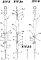
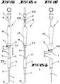
- perspektivisch und mittels eines Aufbruches verkürzt eine erfindungsgemäße Biopsiezange gemäß einem ersten bevorzugten Ausführungsbeispiel, bei geöffnetem Zangenmaul;
- Fig. 2
- eine Ausschnittsvergrößerung von Detail
II aus Figur 1 ; - Fig. 3
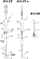
- in einer ersten Seitenansicht die in
Figur 1 - Fig. 3a
- die in
Figur 3 - Fig. 4
- in
einer zu Figur 3 vergleichbaren Seitenansicht die dort gezeigte Biopsiezange in einer weiteren Gebrauchsstellung; - Fig. 5
- in
einer zu Figur 3 vergleichbaren Seitenansicht die dort gezeigte Biopsiezange, jedoch in einer weiteren Gebrauchsstellung, - Fig. 5a
- die in
Figur 5 - Fig. 6
- eine Ausschnittsvergrößerung von Detail
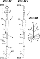
VI gemäß Figur 5 ; - Fig. 7
- in
einer zu Figur 5 vergleichbaren Seitenansicht die dortige Biopsiezange, jedoch in einer noch weiteren Gebrauchsstellung, - Fig. 7a
- die in
Figur 7 - Fig. 8
- eine Ausschnittsvergrößerung von Detail VIII gemäß
Figur 7a ; - Fig. 9
- in
einer zu Figur 7 vergleichbaren Seitenansicht die dortige Biopsiezange, jedoch in einer noch weiteren Gebrauchsstellung, - Fig. 9a
- die in
Figur 9 - Fig. 10
- eine Ausschnittsvergrößerung von Detail
X gemäß Figur 9 ; - Fig. 11
- einen Längsschnitt entlang der Ebene XI-XI in
Figur 9 - Fig. 11a
- eine Ausschnittsvergrößerung von Detail XIa in
Figur 11 - Fig. 11b
- eine Ausschnittsvergrößerung von Detail XIb in
Figur 11 - Fig. 12
- eine Schnittansicht entlang Schnittebene XII-XII in
Figur 9a ; - Fig. 13
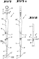
- perspektivisch und mittels eines Aufbruches verkürzt eine erfindungsgemäße Biopsiezange gemäß einem zweiten bevorzugten Ausführungsbeispiel, bei geöffnetem Zangenmaul;
- Fig. 14
- eine Ausschnittsvergrößerung von Detail
XIV aus Figur 13 ; - Fig. 15
- in einer ersten Seitenansicht die in
Figur 13 - Fig. 15a
- die in
Figur 15 - Fig. 16
- in einer zu
Figur 15 vergleichbaren Seitenansicht die dort gezeigte Biopsiezange in einer weiteren Gebrauchsstellung; - Fig. 17
- in einer zu
Figur 15 vergleichbaren Seitenansicht die dort gezeigte Biopsiezange, jedoch in einer weiteren Gebrauchsstellung, - Fig. 17a
- die in
Figur 17 - Fig. 18
- eine Ausschnittsvergrößerung von Detail
XVIII gemäß Figur 17 ; - Fig. 19
- in einer zu
Figur 17 vergleichbaren Seitenansicht die dortige Biopsiezange, jedoch in einer noch weiteren Gebrauchsstellung, - Fig. 19a
- die in
Figur 19 - Fig. 20
- eine Ausschnittsvergrößerung von Detail
XX gemäß Figur 19 ; - Fig. 21
- in einer zu
Figur 19 vergleichbaren Seitenansicht die dortige Biopsiezange, jedoch in einer noch weiteren Gebrauchsstellung, - Fig. 21a
- die in
Figur 21 - Fig. 22
- eine Ausschnittsvergrößerung von Detail
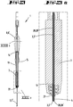
XXII gemäß Figur 21 ; - Fig. 23
- einen Längsschnitt entlang der Ebene XXIII-XXIII in
Figur 21 - Fig. 23a
- eine Ausschnittsvergrößerung von Detail XXIIIa in
Figur 23 - Fig. 23b
- eine Ausschnittsvergrößerung von Detail XXIIIb in
Figur 23 - Fig. 24
- eine Schnittansicht entlang Schnittebene XXIV-XXIV in
Figur 21a ; - Fig. 25
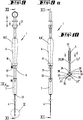
- perspektivisch und mittels eines Aufbruches verkürzt eine erfindungsgemäße Biopsiezange gemäß einem dritten bevorzugten Ausführungsbeispiel, bei geöffnetem Zangenmaul; und
- Fig. 26
- einen Teilschnitt entlang Schnittebene XXIV-XXIV in
Figur 25
- Fig. 1
- perspective and by means of a departure shortens a biopsy forceps according to the invention according to a first preferred embodiment, with open forceps jaw;
- Fig. 2
- a detail enlargement of detail II
FIG. 1 ; - Fig. 3
- in a first side view the in
FIG. 1 shown biopsy forceps, in a first state of use, - Fig. 3a
- in the
FIG. 3 biopsy forceps shown in direction IIIa; - Fig. 4
- in one too
FIG. 3 comparable side view of the biopsy forceps shown there in a further position of use; - Fig. 5
- in one too
FIG. 3 Comparable side view of the biopsy forceps shown there, but in a further position of use, - Fig. 5a
- in the
FIG. 5 shown situation in local Va direction; - Fig. 6
- a detail enlargement of detail VI according to
FIG. 5 ; - Fig. 7
- in one too
FIG. 5 Comparable side view of the local biopsy forceps, but in a still further use position, - Fig. 7a
- in the
FIG. 7 shown situation in local view VIIa; - Fig. 8
- an enlarged detail of detail VIII according to
Figure 7a ; - Fig. 9
- in one too
FIG. 7 Comparable side view of the local biopsy forceps, but in a still further use position, - Fig. 9a
- in the
FIG. 9 shown situation in local view IXa; - Fig. 10
- a detail enlargement of detail X according to
FIG. 9 ; - Fig. 11
- a longitudinal section along the plane XI-XI in
FIG. 9 . - Fig. 11a
- a detail enlargement of detail XIa in
FIG. 11 . - Fig. 11b
- an enlarged detail of detail XIb in
FIG. 11 ; - Fig. 12
- a sectional view along sectional plane XII-XII in
FIG. 9a ; - Fig. 13
- perspective and by means of a departure shortens a biopsy forceps according to the invention according to a second preferred embodiment, with open forceps jaw;
- Fig. 14
- an enlarged detail of detail XIV
FIG. 13 ; - Fig. 15
- in a first side view the in
FIG. 13 shown biopsy forceps, in a first state of use, - Fig. 15a
- in the
FIG. 15 shown biopsy forceps in local view XVa; - Fig. 16
- in one too
FIG. 15 comparable side view of the biopsy forceps shown there in a further position of use; - Fig. 17
- in one too
FIG. 15 Comparable side view of the biopsy forceps shown there, but in a further position of use, - Fig. 17a
- in the
FIG. 17 shown situation in local view XVI-Ia; - Fig. 18
- a detail enlargement of detail XVIII according to
FIG. 17 ; - Fig. 19
- in one too
FIG. 17 Comparable side view of the local biopsy forceps, but in a still further use position, - Fig. 19a
- in the
FIG. 19 shown situation in the line of sight XI-Xa; - Fig. 20
- an enlarged detail of detail XX according to
FIG. 19 ; - Fig. 21
- in one too
FIG. 19 Comparable side view of the local biopsy forceps, but in a still further use position, - Fig. 21a
- in the
FIG. 21 shown situation in the direction of XXIa; - Fig. 22
- a detail enlargement of detail XXII according to
FIG. 21 ; - Fig. 23
- a longitudinal section along the plane XXIII-XXIII in
FIG. 21 ; - Fig. 23a
- an enlarged detail of detail XXIIIa in
FIG. 23 ; - Fig. 23b
- an enlarged detail of detail XXIIIb in
FIG. 23 ; - Fig. 24
- a sectional view along sectional plane XXIV-XXIV in
FIG. 21a ; - Fig. 25
- in perspective and by means of a departure a biopsy forceps according to the invention according to a third preferred embodiment, with open forceps jaw; and
- Fig. 26
- a partial section along sectional plane XXIV-XXIV in
FIG. 25 ,
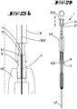
Mit Bezug auf die
Die flexible Ummantelung 4 ist in dem Beispiel an ihrem proximalen Längsende 10 mit der Halteeinrichtung 7 fest verbunden. Das erste Zug-/Schubteil 3 ist an seinem proximalen Längsende 11 (vgl.
Die Biopsiezange 1 weist eine Wegbegrenzungseinrichtung 15 auf, bei der es sich in dem Beispiel um eine Hülse 16 handelt. Diese ist auf den Führungskern 13 aufgeschoben. Der Innendurchmesser der Hülse 16 entspricht im Wesentlichen dem Außendurchmesser des Führungskerns 13, so dass eine spielarme Führung entlang der Betätigungsrichtung X resultiert. Die Hülse 16 besitzt in ihrer Wandung eine durchgehende radiale Gewindebohrung 17, durch welche eine Klemmschraube 18 geschraubt ist. Wird die Klemmschraube eingedreht, drückt sie schließlich gegen den Führungskern 13, wodurch die Wegbegrenzungseinrichtung 15 an der Längsführung 9 in einer gewünschten Position festgeklemmt wird. In diesem befestigten Zustand bildet die Wegbegrenzungseinrichtung 15 einen Anschlag, der den möglichen Verschiebeweg der ersten Betätigungseinrichtung 8 relativ zu der Halteeinrichtung 7 in distaler Richtung entlang der Betätigungsrichtung X begrenzt.The
In den
Abweichend davon wurde bei dem in
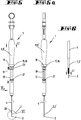
Bei dem gewählten Ausführungsbeispiel umfasst der Zangenkopf 2 zwei Branchen 24. Anstelle von Branchen könnte auch von vorderen Zangenschenkeln gesprochen werden. Beide Branchen 24 sind zwischen einer Geschlossenstellung und einer maximalen Offenstellung des Zangenkopfes bewegbar. Zur Bewegung ist vorgesehen, dass die Handhabungseinrichtung 6 eine zweite Betätigungseinrichtung 25 sowie ein ihr zugeordnetes Führungsteil 26, das mit der zweiten Betätigungseinrichtung 25 eine zweite Längsführung 27 bildet, aufweist. Das Führungsteil 26 ist an dem proximalen Längsende des Handgriffes 8' befestigt und erstreckt sich in dessen geradliniger Verlängerung. Zur Bewegung der Branchen umfasst die Biopsiezange 1 des Weiteren ein zweites Zug-/Schubteil 28. In dem Beispiel handelt es sich um einen Draht 28', der aus mehreren, an ihren Längsenden miteinander verbundenen Drahtstücken gebildet ist. Der Draht 28' steht an seinem distalen Längsende 29 (vgl.
Beide Branchen 24 sind an dem Zangenkopf 2 drehbar an einem Gelenk 38 gehalten. An jede Branche 24 schließt sich proximal ein Hebelstück (jeweils mit 33 bezeichnet) an, das an seinem proximalen Ende mit je einem Hebelteil 34 gelenkig verbunden ist. Jedes Hebelteil 34 ist wiederum an seinem proximalen Ende mit dem distalen Längsende 29 des zweiten Zug-/Schubteils 28, d.h. des Drahtes 28', verbunden.Both
Das Führungsteil 26 ist als zweiter Führungsdorn ausgebildet, und die Griffspule 25' ist in der Betätigungsrichtung x verschieblich auf dem zweiten Führungsdorn aufgeschoben. Die Betätigungsrichtung x verläuft parallel zu der schon beschriebenen Betätigungsrichtung X der ersten Betätigungseinrichtung 8. In den
In dem Beispiel ist die flexible Ummantelung 4 aus dem Kunststoff Polyetheretherketon (PEEK) hergestellt. Die Handhabungseinrichtung 6 weist an ihrem distalen Längsende an der Halteeinrichtung 7 einen Luer-Lock-Anschluss 37 zum Anschließen an einen Arbeitsgang eines Endoskops auf. Bei dem in den
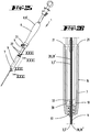
Abweichend davon ist bei dem in den
Das in den
Claims (12)
- Biopsy forceps (1), in particular puncture biopsy forceps,
the biopsy forceps (1) comprising a forceps head (2),
the biopsy forceps (1) comprising a first pull/push part (3), on the distal longitudinal end of which the forceps head (2) is attached,
the biopsy forceps (1) comprising flexible sheathing (4) which has a hollow conduit (5) through which the first pull/push part (3) is longitudinally displaceably guided relative to the flexible sheathing (4),
the biopsy forceps (1) comprising a handling device (6) which has a holding device (7) and a first actuation device (8),
the holding device (7) and the first actuation device (8) together forming a first longitudinal guide (9), by means of which the first actuation device (8) is displaceably guided on the holding device (7), relative thereto, in an actuation direction (X),
the flexible sheathing (4) being connected, in particular at its proximal longitudinal end (10), to the holding device (7),
the first pull/push part (3) being connected, in particular at its proximal longitudinal end (11), to the first actuation device (8),
the biopsy forceps (1) comprising a path-limiting device (15), which can be detachably fastened to the first longitudinal guide (9) at positions that can be selected on the basis of the stated actuation direction (X), and which, in the fastened state, forms a stop which limits a displacement path of the first actuation device (8) in the distal direction relative to the holding device (7), the holding device (7) comprising a guide core, the first actuation device (8) comprising a guide sleeve (14), the guide core (13) and the guide sleeve together forming the first longitudinal guide (9), the path-limiting device (15) comprising a sleeve (16) which is pushed onto the guide core (13), the sleeve (16) comprising in its wall a threaded hole (17) into which a clamping screw (18) is screwed, the sleeve (16) being displaceable on the guide core (13) when the clamping screw (18) is loosened and the sleeve (16) being fixed on the guide core (13) when the clamping screw (18) is tightened, characterised in that a plurality of markings (22), in particular numbers, which are spaced apart from one another in the actuation direction (X), are applied to the guide core (13), the sleeve comprising a cut out (23) through which the markings (22) can be read. - Biopsy forceps (1) according to claim 1, characterised in that the forceps head (2) comprises two branches, it being possible to move one branch or both branches between a closed position and an open position.
- Biopsy forceps (1) according to one or more of the preceding claims, characterised in that, if the first actuation device (8) is located, relative to the holding device (7), in a proximal end position determined by a proximal stop, the forceps head (2) is held in the flexible sheathing (4) and in that, if the sleeve (16) and the first actuation device (8) are located, relative to the holding device (7), in a distal end position determined by a distal stop of the holding device (7), the forceps head (2) and a longitudinal portion of the first pull/push part (3), which portion is proximally adjacent thereto, projects distally from the distal longitudinal end of the flexible sheathing (4).
- Biopsy forceps (1) according to one or more of the preceding claims, characterised in that the handling device (6) comprises a second actuation device (25) and a guide part (26) which, together with the second actuation device (25), forms a second longitudinal guide (27) and is fastened to or formed on the first actuation device (8), in particular on the proximal end thereof, in that the biopsy forceps (1) comprises a second pull/push part (28) which extends in its longitudinal direction as far as the second actuation device (25) so as to be displaceable through a particular hollow conduit of the flexible sheathing (4), the holding device (7), the first actuation device (8) and the guide part (26) and which second pull/push part is fastened at its proximal longitudinal end to the second actuation device (25) and is connected at its distal longitudinal end (29) to the branches (24).
- Biopsy forceps (1) according to one or more of the preceding claims, characterised in that the first pull/push part (3) is formed as a small tube (3') or at least comprises a small tube (3'), in that the second pull/push part (28) is formed as a wire (28') or at least comprises one wire (28') and in that the second pull/push part (28) is displaceably guided in its longitudinal direction through a hollow conduit (30) of the first pull/push part (3).
- Biopsy forceps according to one or more of the preceding claims, characterised in that one branch or in that both branches (24) is/are held on the forceps head (2) so as to be rotatable on a joint (38), in that a lever piece (33) is proximally connected to each rotatable branch (24) and is hingedly connected at its proximal end to a lever part (34) in each case, and in that each lever part (34) is connected at its proximal end to the distal longitudinal end (29) of the second pull/push part (28).
- Biopsy forceps (1) according to one or more of the preceding claims, characterised in that the proximal side of the first actuation device (8) is connected to the guide part (26) which is formed as a second guide pin, in that the second actuation device (25) is in the form of a grip coil (25') and is displaceably pushed onto the second guide pin in an actuation direction (x).
- Biopsy forceps (1) according to one or more of the preceding claims, characterised in that a first branch (24') is longer than the second branch (24") so that, in the closed position, said first branch extends distally further than the second branch (24"), the first branch (24') in particular being tapered at its free longitudinal end to a tip (35).
- Biopsy forceps (1) according to one or more of the preceding claims, characterised in that the first branch (24') comprises a lateral recess (36) which, in the closed position, is geometrically suitable for receiving the second branch (24") in part or completely.
- Biopsy forceps (1) according to one or more of the preceding claims, characterised in that one or both branches (24) is or are held so as to be pivotable on the forceps head (2) and can be moved, relative to the distal longitudinal end (29) of the first pull/push part (3), by means of the second pull/push part (28).
- Biopsy forceps (1) according to one or more of the preceding claims, characterised in that the flexible sheathing (4) is made of plastics material, in particular of polyether ether ketone (PEEK).
- Biopsy forceps (1) according to one or more of the preceding claims, characterised in that the handling device (6) comprises at its distal longitudinal end a Luer connector or a Luer-lock connector (37) for connection to a working conduit of an endoscope.
Applications Claiming Priority (1)
| Application Number | Priority Date | Filing Date | Title |
|---|---|---|---|
| DE202015105488.2U DE202015105488U1 (en) | 2015-10-16 | 2015-10-16 | biopsy forceps |
Publications (2)
| Publication Number | Publication Date |
|---|---|
| EP3155973A1 EP3155973A1 (en) | 2017-04-19 |
| EP3155973B1 true EP3155973B1 (en) | 2019-03-20 |
Family
ID=57130196
Family Applications (1)
| Application Number | Title | Priority Date | Filing Date |
|---|---|---|---|
| EP16192977.3A Not-in-force EP3155973B1 (en) | 2015-10-16 | 2016-10-10 | Biopsy forceps |
Country Status (2)
| Country | Link |
|---|---|
| EP (1) | EP3155973B1 (en) |
| DE (1) | DE202015105488U1 (en) |
Families Citing this family (1)
| Publication number | Priority date | Publication date | Assignee | Title |
|---|---|---|---|---|
| CN106236155A (en) * | 2016-09-13 | 2016-12-21 | 张卫民 | A kind of multi-functional continuous biopsy forceps |
Family Cites Families (5)
| Publication number | Priority date | Publication date | Assignee | Title |
|---|---|---|---|---|
| JPH10276967A (en) * | 1997-04-09 | 1998-10-20 | Olympus Optical Co Ltd | Flexible body for insertion |
| JP2002224121A (en) * | 2001-02-06 | 2002-08-13 | Fuji Photo Optical Co Ltd | Treating implement for endoscope |
| WO2007055032A1 (en) * | 2005-11-14 | 2007-05-18 | Olympus Medical Systems Corp. | Method of endoscopical diagnosis or treatment and medical device |
| US8197396B2 (en) * | 2006-04-26 | 2012-06-12 | Olympus Medical Systems Corp. | Treatment tool for endoscope and medical procedure |
| US8517955B2 (en) * | 2009-05-08 | 2013-08-27 | Broncus Medical Inc. | Tissue sampling devices, systems and methods |
-
2015
- 2015-10-16 DE DE202015105488.2U patent/DE202015105488U1/en active Active
-
2016
- 2016-10-10 EP EP16192977.3A patent/EP3155973B1/en not_active Not-in-force
Non-Patent Citations (1)
| Title |
|---|
| None * |
Also Published As
| Publication number | Publication date |
|---|---|
| EP3155973A1 (en) | 2017-04-19 |
| DE202015105488U1 (en) | 2017-01-17 |
Similar Documents
| Publication | Publication Date | Title |
|---|---|---|
| EP3028623B1 (en) | Endoscopic instrument and endoscopic instrument system | |
| DE102008052178B4 (en) | Clamping instrument for an endoscopic surgical device | |
| EP0639954B1 (en) | Medical instrument for atherectomy | |
| DE19908721A1 (en) | Instrument for cutting biological and especially human tissue | |
| DE102010037618A1 (en) | Medical device | |
| WO2005074787A1 (en) | Endoscope comprising a flexible probe | |
| DE2849694B2 (en) | Surgical instrument for operations on joints | |
| DE602004012173T2 (en) | Wire basket forceps | |
| EP2745781A1 (en) | Endoscopic instrument for retrograde biopsy, in particular synovial biopsy | |
| DE102005017204B4 (en) | Endoscope and method for introducing an optical fiber into a working channel of an endoscope | |
| DE102014101602A1 (en) | Retractor and operating method | |
| EP2361040B1 (en) | Instrument for laparoscopic surgery | |
| EP3155973B1 (en) | Biopsy forceps | |
| EP2340759A1 (en) | Endoscopic instrument | |
| DE102012219342A1 (en) | Endoscopy and biopsy disposable system | |
| DE202005008481U1 (en) | Endoscopic puncture arrangement comprises a hollow puncture needle and a slidable element held together by a sleeve or a hose, and a sleeve joining the catheter distal end to a flexible metal helix | |
| EP3968836B1 (en) | Tissue clip application fitting or retrofitting set | |
| DE102015116652A1 (en) | Endoscope handle | |
| EP3066997B1 (en) | Endoscopic device | |
| DE102017113069A1 (en) | Transporter of a resectoscope and electrode instrument | |
| DE102013110415A1 (en) | Targeting device - needle guide | |
| DE102016001292A1 (en) | Surgical stone catching instrument | |
| DE102009037045A1 (en) | Tubular shaft for surgical instrument, particularly morcellator, shaver or reamer, has rigid section and longitudinally extended tubular element, which has opposite longitudinally movable sections | |
| EP3049143B1 (en) | Positioning device for a medical catheter | |
| DE102016010548A1 (en) | carrier |
Legal Events
| Date | Code | Title | Description |
|---|---|---|---|
| PUAI | Public reference made under article 153(3) epc to a published international application that has entered the european phase |
Free format text: ORIGINAL CODE: 0009012 |
|
| STAA | Information on the status of an ep patent application or granted ep patent |
Free format text: STATUS: THE APPLICATION HAS BEEN PUBLISHED |
|
| AK | Designated contracting states |
Kind code of ref document: A1 Designated state(s): AL AT BE BG CH CY CZ DE DK EE ES FI FR GB GR HR HU IE IS IT LI LT LU LV MC MK MT NL NO PL PT RO RS SE SI SK SM TR |
|
| AX | Request for extension of the european patent |
Extension state: BA ME |
|
| STAA | Information on the status of an ep patent application or granted ep patent |
Free format text: STATUS: REQUEST FOR EXAMINATION WAS MADE |
|
| 17P | Request for examination filed |
Effective date: 20171019 |
|
| RBV | Designated contracting states (corrected) |
Designated state(s): AL AT BE BG CH CY CZ DE DK EE ES FI FR GB GR HR HU IE IS IT LI LT LU LV MC MK MT NL NO PL PT RO RS SE SI SK SM TR |
|
| RIC1 | Information provided on ipc code assigned before grant |
Ipc: A61B 17/34 20060101ALI20180807BHEP Ipc: A61B 10/06 20060101AFI20180807BHEP Ipc: A61B 10/04 20060101ALI20180807BHEP Ipc: A61B 90/00 20160101ALN20180807BHEP |
|
| GRAP | Despatch of communication of intention to grant a patent |
Free format text: ORIGINAL CODE: EPIDOSNIGR1 |
|
| STAA | Information on the status of an ep patent application or granted ep patent |
Free format text: STATUS: GRANT OF PATENT IS INTENDED |
|
| INTG | Intention to grant announced |
Effective date: 20181008 |
|
| GRAS | Grant fee paid |
Free format text: ORIGINAL CODE: EPIDOSNIGR3 |
|
| GRAA | (expected) grant |
Free format text: ORIGINAL CODE: 0009210 |
|
| STAA | Information on the status of an ep patent application or granted ep patent |
Free format text: STATUS: THE PATENT HAS BEEN GRANTED |
|
| AK | Designated contracting states |
Kind code of ref document: B1 Designated state(s): AL AT BE BG CH CY CZ DE DK EE ES FI FR GB GR HR HU IE IS IT LI LT LU LV MC MK MT NL NO PL PT RO RS SE SI SK SM TR |
|
| REG | Reference to a national code |
Ref country code: GB Ref legal event code: FG4D Free format text: NOT ENGLISH |
|
| REG | Reference to a national code |
Ref country code: CH Ref legal event code: EP Ref country code: CH Ref legal event code: NV Representative=s name: R.A. EGLI AND CO, PATENTANWAELTE, CH |
|
| REG | Reference to a national code |
Ref country code: DE Ref legal event code: R096 Ref document number: 502016003798 Country of ref document: DE |
|
| REG | Reference to a national code |
Ref country code: AT Ref legal event code: REF Ref document number: 1109657 Country of ref document: AT Kind code of ref document: T Effective date: 20190415 |
|
| REG | Reference to a national code |
Ref country code: IE Ref legal event code: FG4D Free format text: LANGUAGE OF EP DOCUMENT: GERMAN |
|
| REG | Reference to a national code |
Ref country code: NL Ref legal event code: FP |
|
| PG25 | Lapsed in a contracting state [announced via postgrant information from national office to epo] |
Ref country code: SE Free format text: LAPSE BECAUSE OF FAILURE TO SUBMIT A TRANSLATION OF THE DESCRIPTION OR TO PAY THE FEE WITHIN THE PRESCRIBED TIME-LIMIT Effective date: 20190320 Ref country code: LT Free format text: LAPSE BECAUSE OF FAILURE TO SUBMIT A TRANSLATION OF THE DESCRIPTION OR TO PAY THE FEE WITHIN THE PRESCRIBED TIME-LIMIT Effective date: 20190320 Ref country code: NO Free format text: LAPSE BECAUSE OF FAILURE TO SUBMIT A TRANSLATION OF THE DESCRIPTION OR TO PAY THE FEE WITHIN THE PRESCRIBED TIME-LIMIT Effective date: 20190620 Ref country code: FI Free format text: LAPSE BECAUSE OF FAILURE TO SUBMIT A TRANSLATION OF THE DESCRIPTION OR TO PAY THE FEE WITHIN THE PRESCRIBED TIME-LIMIT Effective date: 20190320 |
|
| REG | Reference to a national code |
Ref country code: LT Ref legal event code: MG4D |
|
| PG25 | Lapsed in a contracting state [announced via postgrant information from national office to epo] |
Ref country code: BG Free format text: LAPSE BECAUSE OF FAILURE TO SUBMIT A TRANSLATION OF THE DESCRIPTION OR TO PAY THE FEE WITHIN THE PRESCRIBED TIME-LIMIT Effective date: 20190620 Ref country code: LV Free format text: LAPSE BECAUSE OF FAILURE TO SUBMIT A TRANSLATION OF THE DESCRIPTION OR TO PAY THE FEE WITHIN THE PRESCRIBED TIME-LIMIT Effective date: 20190320 Ref country code: RS Free format text: LAPSE BECAUSE OF FAILURE TO SUBMIT A TRANSLATION OF THE DESCRIPTION OR TO PAY THE FEE WITHIN THE PRESCRIBED TIME-LIMIT Effective date: 20190320 Ref country code: GR Free format text: LAPSE BECAUSE OF FAILURE TO SUBMIT A TRANSLATION OF THE DESCRIPTION OR TO PAY THE FEE WITHIN THE PRESCRIBED TIME-LIMIT Effective date: 20190621 Ref country code: HR Free format text: LAPSE BECAUSE OF FAILURE TO SUBMIT A TRANSLATION OF THE DESCRIPTION OR TO PAY THE FEE WITHIN THE PRESCRIBED TIME-LIMIT Effective date: 20190320 |
|
| PG25 | Lapsed in a contracting state [announced via postgrant information from national office to epo] |
Ref country code: CZ Free format text: LAPSE BECAUSE OF FAILURE TO SUBMIT A TRANSLATION OF THE DESCRIPTION OR TO PAY THE FEE WITHIN THE PRESCRIBED TIME-LIMIT Effective date: 20190320 Ref country code: RO Free format text: LAPSE BECAUSE OF FAILURE TO SUBMIT A TRANSLATION OF THE DESCRIPTION OR TO PAY THE FEE WITHIN THE PRESCRIBED TIME-LIMIT Effective date: 20190320 Ref country code: IT Free format text: LAPSE BECAUSE OF FAILURE TO SUBMIT A TRANSLATION OF THE DESCRIPTION OR TO PAY THE FEE WITHIN THE PRESCRIBED TIME-LIMIT Effective date: 20190320 Ref country code: PT Free format text: LAPSE BECAUSE OF FAILURE TO SUBMIT A TRANSLATION OF THE DESCRIPTION OR TO PAY THE FEE WITHIN THE PRESCRIBED TIME-LIMIT Effective date: 20190720 Ref country code: AL Free format text: LAPSE BECAUSE OF FAILURE TO SUBMIT A TRANSLATION OF THE DESCRIPTION OR TO PAY THE FEE WITHIN THE PRESCRIBED TIME-LIMIT Effective date: 20190320 Ref country code: SK Free format text: LAPSE BECAUSE OF FAILURE TO SUBMIT A TRANSLATION OF THE DESCRIPTION OR TO PAY THE FEE WITHIN THE PRESCRIBED TIME-LIMIT Effective date: 20190320 Ref country code: EE Free format text: LAPSE BECAUSE OF FAILURE TO SUBMIT A TRANSLATION OF THE DESCRIPTION OR TO PAY THE FEE WITHIN THE PRESCRIBED TIME-LIMIT Effective date: 20190320 Ref country code: ES Free format text: LAPSE BECAUSE OF FAILURE TO SUBMIT A TRANSLATION OF THE DESCRIPTION OR TO PAY THE FEE WITHIN THE PRESCRIBED TIME-LIMIT Effective date: 20190320 |
|
| PG25 | Lapsed in a contracting state [announced via postgrant information from national office to epo] |
Ref country code: SM Free format text: LAPSE BECAUSE OF FAILURE TO SUBMIT A TRANSLATION OF THE DESCRIPTION OR TO PAY THE FEE WITHIN THE PRESCRIBED TIME-LIMIT Effective date: 20190320 Ref country code: PL Free format text: LAPSE BECAUSE OF FAILURE TO SUBMIT A TRANSLATION OF THE DESCRIPTION OR TO PAY THE FEE WITHIN THE PRESCRIBED TIME-LIMIT Effective date: 20190320 |
|
| PG25 | Lapsed in a contracting state [announced via postgrant information from national office to epo] |
Ref country code: IS Free format text: LAPSE BECAUSE OF FAILURE TO SUBMIT A TRANSLATION OF THE DESCRIPTION OR TO PAY THE FEE WITHIN THE PRESCRIBED TIME-LIMIT Effective date: 20190720 |
|
| REG | Reference to a national code |
Ref country code: DE Ref legal event code: R097 Ref document number: 502016003798 Country of ref document: DE |
|
| PLBE | No opposition filed within time limit |
Free format text: ORIGINAL CODE: 0009261 |
|
| STAA | Information on the status of an ep patent application or granted ep patent |
Free format text: STATUS: NO OPPOSITION FILED WITHIN TIME LIMIT |
|
| PG25 | Lapsed in a contracting state [announced via postgrant information from national office to epo] |
Ref country code: DK Free format text: LAPSE BECAUSE OF FAILURE TO SUBMIT A TRANSLATION OF THE DESCRIPTION OR TO PAY THE FEE WITHIN THE PRESCRIBED TIME-LIMIT Effective date: 20190320 |
|
| 26N | No opposition filed |
Effective date: 20200102 |
|
| PG25 | Lapsed in a contracting state [announced via postgrant information from national office to epo] |
Ref country code: SI Free format text: LAPSE BECAUSE OF FAILURE TO SUBMIT A TRANSLATION OF THE DESCRIPTION OR TO PAY THE FEE WITHIN THE PRESCRIBED TIME-LIMIT Effective date: 20190320 |
|
| PG25 | Lapsed in a contracting state [announced via postgrant information from national office to epo] |
Ref country code: TR Free format text: LAPSE BECAUSE OF FAILURE TO SUBMIT A TRANSLATION OF THE DESCRIPTION OR TO PAY THE FEE WITHIN THE PRESCRIBED TIME-LIMIT Effective date: 20190320 |
|
| PG25 | Lapsed in a contracting state [announced via postgrant information from national office to epo] |
Ref country code: MC Free format text: LAPSE BECAUSE OF FAILURE TO SUBMIT A TRANSLATION OF THE DESCRIPTION OR TO PAY THE FEE WITHIN THE PRESCRIBED TIME-LIMIT Effective date: 20190320 |
|
| PG25 | Lapsed in a contracting state [announced via postgrant information from national office to epo] |
Ref country code: LU Free format text: LAPSE BECAUSE OF NON-PAYMENT OF DUE FEES Effective date: 20191010 |
|
| REG | Reference to a national code |
Ref country code: BE Ref legal event code: MM Effective date: 20191031 |
|
| PG25 | Lapsed in a contracting state [announced via postgrant information from national office to epo] |
Ref country code: BE Free format text: LAPSE BECAUSE OF NON-PAYMENT OF DUE FEES Effective date: 20191031 |
|
| PG25 | Lapsed in a contracting state [announced via postgrant information from national office to epo] |
Ref country code: IE Free format text: LAPSE BECAUSE OF NON-PAYMENT OF DUE FEES Effective date: 20191010 |
|
| PG25 | Lapsed in a contracting state [announced via postgrant information from national office to epo] |
Ref country code: CY Free format text: LAPSE BECAUSE OF FAILURE TO SUBMIT A TRANSLATION OF THE DESCRIPTION OR TO PAY THE FEE WITHIN THE PRESCRIBED TIME-LIMIT Effective date: 20190320 |
|
| PG25 | Lapsed in a contracting state [announced via postgrant information from national office to epo] |
Ref country code: MT Free format text: LAPSE BECAUSE OF FAILURE TO SUBMIT A TRANSLATION OF THE DESCRIPTION OR TO PAY THE FEE WITHIN THE PRESCRIBED TIME-LIMIT Effective date: 20190320 Ref country code: HU Free format text: LAPSE BECAUSE OF FAILURE TO SUBMIT A TRANSLATION OF THE DESCRIPTION OR TO PAY THE FEE WITHIN THE PRESCRIBED TIME-LIMIT; INVALID AB INITIO Effective date: 20161010 |
|
| PGFP | Annual fee paid to national office [announced via postgrant information from national office to epo] |
Ref country code: GB Payment date: 20210930 Year of fee payment: 6 |
|
| PGFP | Annual fee paid to national office [announced via postgrant information from national office to epo] |
Ref country code: NL Payment date: 20211019 Year of fee payment: 6 |
|
| PGFP | Annual fee paid to national office [announced via postgrant information from national office to epo] |
Ref country code: DE Payment date: 20211019 Year of fee payment: 6 |
|
| PGFP | Annual fee paid to national office [announced via postgrant information from national office to epo] |
Ref country code: FR Payment date: 20211018 Year of fee payment: 6 Ref country code: CH Payment date: 20211021 Year of fee payment: 6 |
|
| PG25 | Lapsed in a contracting state [announced via postgrant information from national office to epo] |
Ref country code: MK Free format text: LAPSE BECAUSE OF FAILURE TO SUBMIT A TRANSLATION OF THE DESCRIPTION OR TO PAY THE FEE WITHIN THE PRESCRIBED TIME-LIMIT Effective date: 20190320 |
|
| REG | Reference to a national code |
Ref country code: AT Ref legal event code: MM01 Ref document number: 1109657 Country of ref document: AT Kind code of ref document: T Effective date: 20211010 |
|
| PG25 | Lapsed in a contracting state [announced via postgrant information from national office to epo] |
Ref country code: AT Free format text: LAPSE BECAUSE OF NON-PAYMENT OF DUE FEES Effective date: 20211010 |
|
| REG | Reference to a national code |
Ref country code: DE Ref legal event code: R119 Ref document number: 502016003798 Country of ref document: DE |
|
| REG | Reference to a national code |
Ref country code: CH Ref legal event code: PL |
|
| REG | Reference to a national code |
Ref country code: NL Ref legal event code: MM Effective date: 20221101 |
|
| GBPC | Gb: european patent ceased through non-payment of renewal fee |
Effective date: 20221010 |
|
| PG25 | Lapsed in a contracting state [announced via postgrant information from national office to epo] |
Ref country code: NL Free format text: LAPSE BECAUSE OF NON-PAYMENT OF DUE FEES Effective date: 20221101 Ref country code: LI Free format text: LAPSE BECAUSE OF NON-PAYMENT OF DUE FEES Effective date: 20221031 Ref country code: FR Free format text: LAPSE BECAUSE OF NON-PAYMENT OF DUE FEES Effective date: 20221031 Ref country code: DE Free format text: LAPSE BECAUSE OF NON-PAYMENT OF DUE FEES Effective date: 20230503 Ref country code: CH Free format text: LAPSE BECAUSE OF NON-PAYMENT OF DUE FEES Effective date: 20221031 |
|
| PG25 | Lapsed in a contracting state [announced via postgrant information from national office to epo] |
Ref country code: GB Free format text: LAPSE BECAUSE OF NON-PAYMENT OF DUE FEES Effective date: 20221010 |