EP2902872B1 - Handheld device with heat pipe - Google Patents
Handheld device with heat pipe Download PDFInfo
- Publication number
- EP2902872B1 EP2902872B1 EP15153649.7A EP15153649A EP2902872B1 EP 2902872 B1 EP2902872 B1 EP 2902872B1 EP 15153649 A EP15153649 A EP 15153649A EP 2902872 B1 EP2902872 B1 EP 2902872B1
- Authority
- EP
- European Patent Office
- Prior art keywords
- heat
- handheld device
- heat pipe
- circuit board
- electronic component
- Prior art date
- Legal status (The legal status is an assumption and is not a legal conclusion. Google has not performed a legal analysis and makes no representation as to the accuracy of the status listed.)
- Active
Links
Images





Classifications
-
- G—PHYSICS
- G06—COMPUTING OR CALCULATING; COUNTING
- G06F—ELECTRIC DIGITAL DATA PROCESSING
- G06F1/00—Details not covered by groups G06F3/00 - G06F13/00 and G06F21/00
- G06F1/16—Constructional details or arrangements
- G06F1/20—Cooling means
- G06F1/203—Cooling means for portable computers, e.g. for laptops
-
- G—PHYSICS
- G06—COMPUTING OR CALCULATING; COUNTING
- G06F—ELECTRIC DIGITAL DATA PROCESSING
- G06F1/00—Details not covered by groups G06F3/00 - G06F13/00 and G06F21/00
- G06F1/16—Constructional details or arrangements
- G06F1/1613—Constructional details or arrangements for portable computers
- G06F1/1626—Constructional details or arrangements for portable computers with a single-body enclosure integrating a flat display, e.g. Personal Digital Assistants [PDAs]
-
- G—PHYSICS
- G06—COMPUTING OR CALCULATING; COUNTING
- G06F—ELECTRIC DIGITAL DATA PROCESSING
- G06F1/00—Details not covered by groups G06F3/00 - G06F13/00 and G06F21/00
- G06F1/16—Constructional details or arrangements
- G06F1/1613—Constructional details or arrangements for portable computers
- G06F1/1633—Constructional details or arrangements of portable computers not specific to the type of enclosures covered by groups G06F1/1615 - G06F1/1626
- G06F1/1656—Details related to functional adaptations of the enclosure, e.g. to provide protection against EMI, shock, water, or to host detachable peripherals like a mouse or removable expansions units like PCMCIA cards, or to provide access to internal components for maintenance or to removable storage supports like CDs or DVDs, or to mechanically mount accessories
Definitions
- the present disclosure relates to a device that dissipates heat using a heat pipe.
- a heat pipe refers to a heat transfer component that makes use of a principle that, when evaporation and condensation of a medium are repeated within a pipe, heat may be transferred from a heating segment to a heat radiating segment. More specifically, a heat pipe is manufactured by reducing the pressure in the inside of a pipe and introducing a liquid, such as water or alcohol, into the pressure-reduced inside of the pipe. When a heat segment is heated, the liquid is vaporized into vapor and the vapor flows to the other side, and when the vapor releases heat to be condensed to liquid, the liquid returns back to the heating segment again due to a capillary phenomenon.
- Document KR 2014 0000933 A discloses a handheld device according to the preamble of claim 1.
- a heat pipe is used to dissipate heat from an electronic component.
- Documents US 2011/149537 A1 , US 2012/182694 A1 and US 7 545 646 B2 disclose the use of heat sinking materials to bond components of handheld devices.
- FIGURES 1 through 9 discussed below, and the various embodiments used to describe the principles of the present disclosure in this patent document are by way of illustration only and should not be construed in any way to limit the scope of the disclosure. Those skilled in the art will understand that the principles of the present disclosure may be implemented in any suitably arranged electronic devices.
- various embodiments will be described with reference to the accompanying drawings. It should be noted that the same elements will be designated by the same reference numerals although they are shown in different drawings. Further, a detailed description of a known function and configuration which may make the subject matter of the present disclosure unclear will be omitted.
- a handheld device may be implemented to be included in an electronic device.
- An electronic device may be a device including a communication function.
- the electronic device may be a combination of one or more of a smartphone, a tablet personal computer, a mobile phone, a video phone, an e-book reader, a desktop personal computer, a laptop personal computer, a netbook computer, a Personal Digital Assistant (PDA), a Portable Multimedia Player (PMP), an MP3 player, a mobile medical device, an electronic bracelet, an electronic necklace, an electronic accessory, a camera, a wearable device, an electronic clock, a wrist watch, a home appliance (e.g.
- a refrigerator e.g. a refrigerator, an air conditioner, a cleaner, an oven, a microwave oven, a washing machine, a vacuum cleaner, etc.
- an artificial intelligent robot e.g. a Television (TV), a Digital Video Disk (DVD) player, an audio player, various medical machines (e.g. a Magnetic Resonance Angiography (MRA), a Magnetic Resonance Imaging (MRI), a Computed Tomography (CT), a tomography camera, a sonography device, etc.), a navigation device, a Global Positioning System (GPS) receiver, an Event Data Recorder (EDR), a Flight Data Recorder (FDR), a set-top box, a TV box (e.g.
- a vehicle infotainment device electronic equipment for a ship (e.g. navigation equipment for a ship, a gyrocompass, etc.), avionic equipment, a security device, an electronic cloth, an electronic key, a camcorder, a game console, a Head-Mounted Display (HMD), a flat panel display device, an electronic frame, an electronic album, a furniture or a part of a building/structure including a communication function, an electronic board, an electronic signature receiving device, a projector, etc.
- HMD Head-Mounted Display
- heat pipes have been applied to electronic apparatuses having a size that is larger than that of an ordinary notebook computer, or electronic apparatuses operated in a forced-cooling type by being combined with a fan, for example, a refrigerator. Due to the large size, the heat pipes have only been applied to electronic apparatuses over a certain size, without being applied to a handheld device. However, as handheld devices are reduced in size and highly improved in performance, heat generation becomes a serious problem. Accordingly, it is necessary to provide a method of solving the heat generation problem of the handheld devices to reduce the entire temperature of the handheld devices.
- An embodiment of the present disclosure is to provide a handheld device in which a high heat generation portion and a cold portion are connected with each other by a heat pipe so that the entire temperature can be reduced.
- FIG. 1 illustrates a handheld device according to an embodiment of the present disclosure.
- an handheld device 100 includes a circuit board 110 including at least one electronic component 110a, a heat pipe 120 disposed on the electronic component 110a to radiate heat generated from the electronic component 110a, and a heat sinking material configured to bond the circuit board 110 and the heat pipe 120 to each other.
- the handheld device 100 refers to an appliance which can be used by a user in a hand-held state, and can be at least one of, for example, a smart phone, a tablet PC, a mobile phone, a video phone, an e-book reader, a PDA, a PMP, and an MP3 player.
- the circuit board 110 can be referred to as a "mainboard,” on which an electronic component 110a is mounted to provide various functions in the handheld device 100.
- the electronic component 110a can be an Application Processor (AP), a Central Processing Unit (CPU), or a Power Management IC (PMIC).
- AP Application Processor
- CPU Central Processing Unit
- PMIC Power Management IC
- the electronic component 110a is a main heat generating source that generates heat in the handheld device. Accordingly, the heat pipe 120 is disposed on the electronic component 110a to radiate the heat generated from the electronic component 110a to another place.
- the heat pipe 120 includes an evaporation section disposed on the electronic component 110a to absorb the heat generated from the circuit board 110, a connection section formed on a side region of the circuit board 110 to transfer the absorbed heat in a direction away from the electronic component 110a, and a condensation section that radiates the heat transferred thereto.
- the handheld device 100 can further include a battery mounting unit where a battery 130 is mounted, and an auxiliary board 140.
- the battery 130 has an important role with the circuit board 110 in the handheld device 100 in that the battery 130 serves to supply power to the handheld device 100. Accordingly, the circuit board 110 and the battery 130 can be formed to be relatively larger than other components. In addition, similarly to the circuit board 110, any other component, which is not mounted on the circuit board 110, can be mounted on the auxiliary board 140.
- the heat pipe 120 can have a large thickness in order to absorb the heat of the electronic component 110a and radiate the heat to the battery. Considering the width of the handheld device, it is difficult to insert the heat pipe 120 in a case where the heat pipe 120 is configured to directly connect the electronic component 110a to the battery 130. Accordingly, a method of inserting the heat pipe 120 into the handheld device 100 without increasing the thickness of the handheld device 100 is to insert the heat pipe 120 into a region on a lateral side of the battery 130. That is, in the present disclosure, the heat pipe 120, extending from the electronic component 110a serving as a main heat generating source, can be positioned in the region on a side of the battery 130.
- connection section in order to insert the heat pipe 120 into the lateral side of the battery 130, can be bent by a predetermined angle from the evaporation section.
- the predetermined angle can be set depending on the size of the electronic component and the area of the region on the lateral side of the battery on the circuit board 110 in which the connection section is disposed.
- the heat pipe 120 can be affected by gravity, a structure, in which the circuit board 110 is positioned in a lower portion and the battery 130 is positioned in the upper end portion, can be more advantageous.
- a 3D game which can generate excessive heat, is enjoyed in a state where the handheld device 100 is laid horizontally, the handheld device 100 can be less affected by the gravity under a practical use condition.
- the performance of the heat pipe 120 can be degraded due to the effect of gravity.
- the cooling effect by natural convection is improved, the performance degradation of the heat pipe 120 can be compensated.
- FIGS. 2A to 2C illustrate handheld devices according to the embodiments of the present disclosure.
- the circuit board 110 in a handheld device 210, can be disposed in a lower portion, the battery 130 can be disposed in an upper portion with reference to the circuit board 110, the heat pipe 120 can be disposed on a lateral side of the battery 130, and the auxiliary board 140 can be disposed in the uppermost portion. That is, upon comparing the handheld device 210 with the handheld device 100 illustrated in FIG. 1 , the positions of the circuit board 110 and the battery 130 can be reversed. Accordingly, the heat pipe 120 can move and radiate the heat, which is generated from the electronic component 110a mounted on the circuit board 110 in a direction away from the electronic component 110a, towards the auxiliary board 140.
- the circuit board 110 and the battery 130 can be disposed to face each other. That is, in the handheld device 220, the circuit board 110 can be disposed on the left and the battery 130 can be disposed on the right.
- the heat pipe 120 can move and radiate the heat, which is generated from the electronic component 110a on the circuit board 110, towards the lower portion. At this time, the heat pipe 120 can be disposed at a long distance from the battery 130.
- the battery 130 in a handheld device 230, can be disposed on the left and the circuit board 110 can be disposed on the right so that the circuit board 110 and the battery 130 face each other.
- the electronic component 110a can be disposed in a central portion of the circuit board 110, and the heat pipe 120 can radiate the heat generated from the electronic component 110a while moving the heat upwardly and downwardly. At this time, the heat pipe 120 can be disposed in a region adjacent to the battery 130.
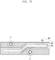
- FIG. 3 illustrates an example in which a heat pipe is disposed on a circuit board according to an embodiment of the present disclosure illustrated in FIG. 1 .
- the heat pipe includes an evaporation section 310 disposed on an electronic component to absorb heat generated from the electronic component, a connection section 320 formed on a lateral side of the circuit board to transfer the absorbed heat in a direction away from the electronic component, and a condensation section 330 that radiates the heat transferred thereto.
- the evaporation section 310 absorbs the heat generated from the electronic component, the medium therein is vaporized to vapor.
- the vapor of the medium generated by the absorbed heat can move to the condensation section 330 along the connection section 320.
- the connection section 320 can be formed between the circuit board and the auxiliary board to be superposed with a side region of the circuit board facing the battery.
- the vapor vaporised from the medium by the absorbed heat is capable of releasing heat while being condensed to liquid in the condensation section 330.
- the liquid condensed by releasing the heat is capable of moving again to the evaporation section 310 along the connection section 320. That is, the evaporation section 310 can be disposed adjacent to the electronic component, and the condensation section 320 can be disposed at a longer distance from the electronic component than the evaporation section 310.
- the heat pipe is capable of dissipating the heat generated from the circuit board to a position other than the circuit board within the handheld device.
- FIGS. 4A and 4C illustrate heat pipes according to an embodiment of the present disclosure.
- FIGS. 4A and 4B illustrate the cross-sectional views of a handheld device 400a which is taken along a line corresponding to line X2 in FIG. 3 .
- the portion sectioned along line X2 corresponds to a portion where the connection section of the heat pipe is formed.
- the heat pipe can include a vapor cavity 410, a wick 420, and a heat conductive member 430.
- the phase of the medium is changed to vapor in the vapor cavity 410.
- the medium changed to vapor moves to the condensation section along the vapor cavity 410 so that the absorbed heat is released from the medium.
- the wick 420 surrounds the vapor cavity 410, and the vaporized medium releases heat in the condensation section to be subjected to phase change so that the vaporized medium is changed to liquid.
- the medium changed to liquid is transferred to the evaporation section again along the wick 420.
- the heat conductive member 430 is formed to surround the wick 420. The heat conductive member 430 serves to enhance heat conductivity.
- the heat conductive member 430 can be made of at least one of aluminum (Al), copper (Cu), silver (Ag), titanium (Ti), chrome (Cr), gold (Au), carbon (C), nickel (Ni), ferrite (Fe), platinum (Pt), graphite and boron nitride (BN), or a combination thereof.
- the side region of the circuit board, on which the connection section circuit board 450 is provided is a narrow portion that is positioned on a lateral side of the battery to interconnect the circuit board 450 and the auxiliary board.
- the side region is referred to as an anaxhandle-shaped portion due to its shape and is weak due to its narrow width. Accordingly, the side region can be broken in the process of assembly and handling. Accordingly, in a conventional handheld device 400b, the circuit board 450 is lined with a reinforcing plate 460 made of a material of a ferrite component in order to reinforce the region of the circuit board.
- the reinforcing plate 460 is well bonded to the circuit board 450 through solder 470.
- the heat pipe is also disposed on the side region of circuit board 450 so that the heat pipe can fill the role of the reinforcing plate 460.
- a plurality of channels can be provided in some embodiments. For example, since side walls of the channel are higher than the reinforcing plate 460, the channel also plays a role in reinforcing the side region of the circuit board 450.
- the circuit board 450 and the heat pipe are bonded to each other using the heat sinking material 440.
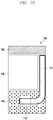
- FIG. 5 illustrates a cross-sectional view of the handheld device according to an embodiment of the present disclosure. More specifically, FIG. 5 is a cross-sectional view taken along a line corresponding to line X1 in FIG. 3 .
- the heat pipe 500 is bent on a portion where an electronic component 530 is mounted, to pass above a H/W component 540.
- a portion 520, on which a highest electronic component 530, such as an AP, is mounted, does not have a space in which the heat pipe 500 is stacked in a z-axis direction.
- the heat conductive member 580 of the heat pipe is formed on the electronic component 530.
- the heat conductive member 580 is capable of transferring heat to the channel constituted with the vapor cavity 560 and the wick 570 by heat conduction through a material having excellent heat conductivity.
- the heat transferred to the channel in this way can be absorbed to the medium through the vapor cavity 560 and the wick 570 as vaporization heat.
- the electronic component 530 and the circuit board 510 can be bonded to the heat pipe 500 through a double-sided tape having excellent heat conductivity or a material having excellent heat conductivity.
- a heat sinking material 550 can be interposed between the circuit board 510 and the heat pipe 500 to improve heat transfer performance.
- the heat sinking material 550 can be a Thermal Interface Materials (TIM).
- the heat sinking interface material 550 can be made of a Phase Change Material (PCM) 550a.
- circuit board 510 and the heat pipe are bonded to each other in order to reinforce the strength
- the circuit board 510 and the heat pipe are bonded to each other mainly for the purpose of improving a heat dissipation effect. Since a conductive layer of the circuit board 510 is made of copper having excellent heat conductivity, the heat conductivity of the circuit board can be improved so that the effect of the heat pipe can be maximized.
- FIGS. 6A and 6B illustrate examples of bonding a phase change material to a circuit board according to an embodiment of the present disclosure.
- the heat pipe can be deformed at temperature over 180°C. Accordingly, the circuit board B and the heat pipe A can be bonded to each other using a phase change material C which is a solid at room temperature but is changed to a gel state at a temperature over a certain level. Accordingly, the phase change material C is excellent in heat conductivity and is capable of reinforcing the adhesion strength between the circuit board B and the heat pipe A. As illustrated in FIGS.
- the reinforcing plate is provided to reinforce the strength so as to prevent flexural or fracture caused by force at the time of assembly or disassembly.
- the assembly or disassembly is performed manually at room temperature, the operation cannot be performed at a temperature over 45°C.
- the phase change material C since the phase change material C is in the solid state at a temperature below 40°C, the phase change material C does not have a problem as an adhesive for maintaining the adhesion of the circuit board B and the heat pipe A.
- the phase change material C is in the gel state.
- the phase change material C is capable of filling fine unevenness between bonded surfaces, thereby removing air gap which is highly insulative. That is, when the circuit board is merely placed on the heat pipe A previously coated with the phase change material C just after the circuit board have been discharged from a Surface Mounting Device (SMD) at a temperature of, for example 270°C or higher, the circuit board B and the heat pipe A can be simply bonded to each other.
- SMD Surface Mounting Device
- the heat pipe A and the circuit board B are bonded to each other at room temperature using the phase change material C, the bonding can be easily performed by using a processing instrument heated to a temperature of about 50°C.
- phase change material C is in the gel state to be softened at a temperature of 50°C or higher, even if a very large gap is formed between the circuit board B and the heat pipe A, the phase change material C is spread to fill the gap between the circuit board B and the heat pipe A. Thus, there will be no problem in bonding.
- an ordinary pad-shaped material D cannot fill unevenness between bonded surfaces. Accordingly, the ordinary pad-shaped material D may not fill the gap between the circuit board B and the heat pipe A.
- the phase change material C can strengthen the bonding force between the circuit board B and the heat pipe A while reducing thermal resistance therebetween.
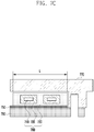
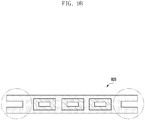
- FIGS. 7A and 7C illustrate examples in which a heat pipe according to an embodiment of the present disclosure is applied to a handheld device.
- the heat pipe can include a vapor cavity 710, a wick 720, and a heat conductive member 730.
- the heat pipe is manufactured in an elongated tubular shape that is cut into a proper length and inserted into a mounting space after it is bent to be suitable for the shape of the mounting space.
- screw holds h are formed on both sides of the heat pipe. Accordingly, the width of the heat pipe should be set considering the screw holes h, as well. Thus, the width of the heat pipe is narrowed and the heat to be transferred by the heat pipe can be reduced.
- the circuit board 760 is bonded with the heat pipe 700 by a heat sinking interface material 750.
- a heat sinking interface material 750 there is a disadvantage in that the entire width L of the heat pipe is narrowed due to the screw holes h.
- the heat pipe 700 can include two channels. The screw holes h can interconnect the circuit board 760 and the external case 770.
- the effective width of the heat pipe can be determined in consideration of the screw holes h, as well.
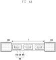
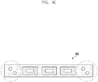
- FIGS. 8A to 8C are views illustrating an example in which a heat pipe according to another embodiment of the present disclosure is applied to a handheld device.
- the heat pipe can include a vapor cavity 810, a wick 820, and a heat conductive member 830.
- the heat conductive member 830 can include a dummy region 840 expanded to screw holes h formed in side regions of a circuit board.
- the dummy regions 840 formed as outskirts of the circuit board can be removed. Accordingly, the heat conductive member 830 of the heat pipe can be expanded to the dummy region 840 so that the sizes of the vapor cavity 810 and the wick 820 within the heat conductive member 830 can be increased. That is, the size of the vapor cavity 810 or the size of the wick 820 can be determined according to the dummy region 840.
- the entire width L' of the heat pipe 800 can be widened compared to the entire width of the heat pipe of FIG. 7C so that the heat pipe 800 can include three channels.
- the circuit board 860 is bonded with the heat pipe 800 by a heat sinking interface material 850.
- a screw hole h can interconnect the circuit board 860 and an external case 870. Accordingly, even if the dummy region 840 formed as a outskirt of the circuit board 860 is removed, a part of the dummy region 840 of the heat conductive member 830 made of a metal which is excellent in heat conductivity remains so that the heat conductivity can be further enhanced.
- FIGS. 9A to 9C illustrate shapes of dummy regions according to embodiments of the present disclosure.
- the dummy regions can include slot holes.
- the slot holes can be alternately formed on both sides or the left and right slot holes can be formed in the opposite directions.
- the dummy regions can be formed in at least one of a concave-convex shape 920, a polygonal shape, and a hole 930.
- the entire temperature of a handheld device can be reduced by interconnecting a high heat generating portion and a cold portion in the handheld device with each other by a heat pipe.
- the performance of a handheld device can be improved by applying a heat pipe to the handheld device.
Landscapes
- Engineering & Computer Science (AREA)
- Theoretical Computer Science (AREA)
- Computer Hardware Design (AREA)
- General Engineering & Computer Science (AREA)
- Human Computer Interaction (AREA)
- Physics & Mathematics (AREA)
- General Physics & Mathematics (AREA)
- Cooling Or The Like Of Electrical Apparatus (AREA)
- Cooling Or The Like Of Semiconductors Or Solid State Devices (AREA)
Description
- The present disclosure relates to a device that dissipates heat using a heat pipe.
- A heat pipe refers to a heat transfer component that makes use of a principle that, when evaporation and condensation of a medium are repeated within a pipe, heat may be transferred from a heating segment to a heat radiating segment. More specifically, a heat pipe is manufactured by reducing the pressure in the inside of a pipe and introducing a liquid, such as water or alcohol, into the pressure-reduced inside of the pipe. When a heat segment is heated, the liquid is vaporized into vapor and the vapor flows to the other side, and when the vapor releases heat to be condensed to liquid, the liquid returns back to the heating segment again due to a capillary phenomenon.
- Document
KR 2014 0000933 A US 2011/149537 A1 ,US 2012/182694 A1 andUS 7 545 646 B2 disclose the use of heat sinking materials to bond components of handheld devices. - To address the above-discussed deficiencies, it is a primary object to provide a handheld device according to appended claim 1.
- Before undertaking the DETAILED DESCRIPTION below, it may be advantageous to set forth definitions of certain words and phrases used throughout this patent document: the terms "include" and "comprise," as well as derivatives thereof, mean inclusion without limitation; the term "or," is inclusive, meaning and/or; the phrases "associated with" and "associated therewith," as well as derivatives thereof, may mean to include, be included within, interconnect with, contain, be contained within, connect to or with, couple to or with, be communicable with, cooperate with, interleave, juxtapose, be proximate to, be bound to or with, have, have a property of, or the like; and the term "controller" means any device, system or part thereof that controls at least one operation, such a device may be implemented in hardware, firmware or software, or some combination of at least two of the same. It should be noted that the functionality associated with any particular controller may be centralized or distributed, whether locally or remotely. Definitions for certain words and phrases are provided throughout this patent document, those of ordinary skill in the art should understand that in many, if not most instances, such definitions apply to prior, as well as future uses of such defined words and phrases.
- For a more complete understanding of the present disclosure and its advantages, reference is now made to the following description taken in conjunction with the accompanying drawings, in which like reference numerals represent like parts:
-
FIG. 1 illustrates a handheld device according to an embodiment of the present disclosure; -
FIGS. 2A to 2C illustrate a handheld device according to another embodiment of the present disclosure; -
FIG. 3 illustrates an example in which a heat pipe is disposed on a circuit board according to embodiments of the present disclosure illustrated inFIG. 1 ; -
FIGS. 4A to 4C illustrate heat pipes according to embodiments of the present disclosure; -
FIG. 5 illustrates a cross-sectional view of the handheld device according to an embodiment of the present disclosure; -
FIGS. 6A to 6B illustrate examples of bonding a phase change material to a circuit board according to embodiments of the present disclosure; -
FIGS. 7A and7C illustrate an example in which a heat pipe is applied to a handheld device according to an embodiment of the present disclosure; -
FIGS. 8A to 8C are views illustrating an example in which a heat pipe is applied to a handheld device according to another embodiment of the present disclosure; and -
FIGS. 9A to 9C illustrate shapes of dummy regions according to embodiments of the present disclosure. -
FIGURES 1 through 9 , discussed below, and the various embodiments used to describe the principles of the present disclosure in this patent document are by way of illustration only and should not be construed in any way to limit the scope of the disclosure. Those skilled in the art will understand that the principles of the present disclosure may be implemented in any suitably arranged electronic devices. Hereinafter, various embodiments will be described with reference to the accompanying drawings. It should be noted that the same elements will be designated by the same reference numerals although they are shown in different drawings. Further, a detailed description of a known function and configuration which may make the subject matter of the present disclosure unclear will be omitted. Hereinafter, it should be noted that only the descriptions will be provided that may help understanding the operations provided in association with the various embodiments of the present disclosure, and other descriptions will be omitted to avoid making the subject matter of the present disclosure rather unclear. - A handheld device according to the present disclosure may be implemented to be included in an electronic device. An electronic device according to the present disclosure may be a device including a communication function. For example, the electronic device may be a combination of one or more of a smartphone, a tablet personal computer, a mobile phone, a video phone, an e-book reader, a desktop personal computer, a laptop personal computer, a netbook computer, a Personal Digital Assistant (PDA), a Portable Multimedia Player (PMP), an MP3 player, a mobile medical device, an electronic bracelet, an electronic necklace, an electronic accessory, a camera, a wearable device, an electronic clock, a wrist watch, a home appliance (e.g. a refrigerator, an air conditioner, a cleaner, an oven, a microwave oven, a washing machine, a vacuum cleaner, etc.), an artificial intelligent robot, a Television (TV), a Digital Video Disk (DVD) player, an audio player, various medical machines (e.g. a Magnetic Resonance Angiography (MRA), a Magnetic Resonance Imaging (MRI), a Computed Tomography (CT), a tomography camera, a sonography device, etc.), a navigation device, a Global Positioning System (GPS) receiver, an Event Data Recorder (EDR), a Flight Data Recorder (FDR), a set-top box, a TV box (e.g. Samsung HomeSync™, Apple TV™, or Google TV™), an electronic dictionary, a vehicle infotainment device, electronic equipment for a ship (e.g. navigation equipment for a ship, a gyrocompass, etc.), avionic equipment, a security device, an electronic cloth, an electronic key, a camcorder, a game console, a Head-Mounted Display (HMD), a flat panel display device, an electronic frame, an electronic album, a furniture or a part of a building/structure including a communication function, an electronic board, an electronic signature receiving device, a projector, etc.. It is obvious to those skilled in the art that the electronic device according to the present disclosure is not limited to the aforementioned devices.
- In the past, heat pipes have been applied to electronic apparatuses having a size that is larger than that of an ordinary notebook computer, or electronic apparatuses operated in a forced-cooling type by being combined with a fan, for example, a refrigerator. Due to the large size, the heat pipes have only been applied to electronic apparatuses over a certain size, without being applied to a handheld device. However, as handheld devices are reduced in size and highly improved in performance, heat generation becomes a serious problem. Accordingly, it is necessary to provide a method of solving the heat generation problem of the handheld devices to reduce the entire temperature of the handheld devices.
- An embodiment of the present disclosure is to provide a handheld device in which a high heat generation portion and a cold portion are connected with each other by a heat pipe so that the entire temperature can be reduced.
-
FIG. 1 illustrates a handheld device according to an embodiment of the present disclosure. Referring toFIG. 1 , anhandheld device 100 includes acircuit board 110 including at least oneelectronic component 110a, aheat pipe 120 disposed on theelectronic component 110a to radiate heat generated from theelectronic component 110a, and a heat sinking material configured to bond thecircuit board 110 and theheat pipe 120 to each other. - According to an embodiment, the
handheld device 100 refers to an appliance which can be used by a user in a hand-held state, and can be at least one of, for example, a smart phone, a tablet PC, a mobile phone, a video phone, an e-book reader, a PDA, a PMP, and an MP3 player. - The
circuit board 110 can be referred to as a "mainboard," on which anelectronic component 110a is mounted to provide various functions in thehandheld device 100. For example, theelectronic component 110a can be an Application Processor (AP), a Central Processing Unit (CPU), or a Power Management IC (PMIC). Theelectronic component 110a is a main heat generating source that generates heat in the handheld device. Accordingly, theheat pipe 120 is disposed on theelectronic component 110a to radiate the heat generated from theelectronic component 110a to another place. - For example, the
heat pipe 120 includes an evaporation section disposed on theelectronic component 110a to absorb the heat generated from thecircuit board 110, a connection section formed on a side region of thecircuit board 110 to transfer the absorbed heat in a direction away from theelectronic component 110a, and a condensation section that radiates the heat transferred thereto. - The
handheld device 100 can further include a battery mounting unit where abattery 130 is mounted, and anauxiliary board 140. Thebattery 130 has an important role with thecircuit board 110 in thehandheld device 100 in that thebattery 130 serves to supply power to thehandheld device 100. Accordingly, thecircuit board 110 and thebattery 130 can be formed to be relatively larger than other components. In addition, similarly to thecircuit board 110, any other component, which is not mounted on thecircuit board 110, can be mounted on theauxiliary board 140. - However, the
heat pipe 120 can have a large thickness in order to absorb the heat of theelectronic component 110a and radiate the heat to the battery. Considering the width of the handheld device, it is difficult to insert theheat pipe 120 in a case where theheat pipe 120 is configured to directly connect theelectronic component 110a to thebattery 130. Accordingly, a method of inserting theheat pipe 120 into thehandheld device 100 without increasing the thickness of thehandheld device 100 is to insert theheat pipe 120 into a region on a lateral side of thebattery 130. That is, in the present disclosure, theheat pipe 120, extending from theelectronic component 110a serving as a main heat generating source, can be positioned in the region on a side of thebattery 130. - According to an embodiment, in order to insert the
heat pipe 120 into the lateral side of thebattery 130, the connection section can be bent by a predetermined angle from the evaporation section. The predetermined angle can be set depending on the size of the electronic component and the area of the region on the lateral side of the battery on thecircuit board 110 in which the connection section is disposed. - In addition, since the
heat pipe 120 can be affected by gravity, a structure, in which thecircuit board 110 is positioned in a lower portion and thebattery 130 is positioned in the upper end portion, can be more advantageous. However, since a 3D game, which can generate excessive heat, is enjoyed in a state where thehandheld device 100 is laid horizontally, thehandheld device 100 can be less affected by the gravity under a practical use condition. In the state where thehandheld device 100 is stood vertically, the performance of theheat pipe 120 can be degraded due to the effect of gravity. However, since the cooling effect by natural convection is improved, the performance degradation of theheat pipe 120 can be compensated. -
FIGS. 2A to 2C illustrate handheld devices according to the embodiments of the present disclosure. Referring toFIG. 2A to 2C , in ahandheld device 210, thecircuit board 110 can be disposed in a lower portion, thebattery 130 can be disposed in an upper portion with reference to thecircuit board 110, theheat pipe 120 can be disposed on a lateral side of thebattery 130, and theauxiliary board 140 can be disposed in the uppermost portion. That is, upon comparing thehandheld device 210 with thehandheld device 100 illustrated inFIG. 1 , the positions of thecircuit board 110 and thebattery 130 can be reversed. Accordingly, theheat pipe 120 can move and radiate the heat, which is generated from theelectronic component 110a mounted on thecircuit board 110 in a direction away from theelectronic component 110a, towards theauxiliary board 140. - In another embodiment, in a
handheld device 220, thecircuit board 110 and thebattery 130 can be disposed to face each other. That is, in thehandheld device 220, thecircuit board 110 can be disposed on the left and thebattery 130 can be disposed on the right. Theheat pipe 120 can move and radiate the heat, which is generated from theelectronic component 110a on thecircuit board 110, towards the lower portion. At this time, theheat pipe 120 can be disposed at a long distance from thebattery 130. - In still another embodiment, in a
handheld device 230, thebattery 130 can be disposed on the left and thecircuit board 110 can be disposed on the right so that thecircuit board 110 and thebattery 130 face each other. Theelectronic component 110a can be disposed in a central portion of thecircuit board 110, and theheat pipe 120 can radiate the heat generated from theelectronic component 110a while moving the heat upwardly and downwardly. At this time, theheat pipe 120 can be disposed in a region adjacent to thebattery 130. -
FIG. 3 illustrates an example in which a heat pipe is disposed on a circuit board according to an embodiment of the present disclosure illustrated inFIG. 1 . - Referring to
FIG. 3 , the heat pipe includes anevaporation section 310 disposed on an electronic component to absorb heat generated from the electronic component, aconnection section 320 formed on a lateral side of the circuit board to transfer the absorbed heat in a direction away from the electronic component, and acondensation section 330 that radiates the heat transferred thereto. When theevaporation section 310 absorbs the heat generated from the electronic component, the medium therein is vaporized to vapor. The vapor of the medium generated by the absorbed heat can move to thecondensation section 330 along theconnection section 320. Theconnection section 320 can be formed between the circuit board and the auxiliary board to be superposed with a side region of the circuit board facing the battery. The vapor vaporised from the medium by the absorbed heat is capable of releasing heat while being condensed to liquid in thecondensation section 330. The liquid condensed by releasing the heat is capable of moving again to theevaporation section 310 along theconnection section 320. That is, theevaporation section 310 can be disposed adjacent to the electronic component, and thecondensation section 320 can be disposed at a longer distance from the electronic component than theevaporation section 310. - Accordingly, the heat pipe is capable of dissipating the heat generated from the circuit board to a position other than the circuit board within the handheld device.
-
FIGS. 4A and4C illustrate heat pipes according to an embodiment of the present disclosure. -
FIGS. 4A and4B illustrate the cross-sectional views of ahandheld device 400a which is taken along a line corresponding to line X2 inFIG. 3 . The portion sectioned along line X2 corresponds to a portion where the connection section of the heat pipe is formed. The heat pipe can include avapor cavity 410, awick 420, and a heatconductive member 430. - Referring to
FIG. 4C , upon absorbing heat from thecircuit board 450, the phase of the medium is changed to vapor in thevapor cavity 410. The medium changed to vapor moves to the condensation section along thevapor cavity 410 so that the absorbed heat is released from the medium. Thewick 420 surrounds thevapor cavity 410, and the vaporized medium releases heat in the condensation section to be subjected to phase change so that the vaporized medium is changed to liquid. The medium changed to liquid is transferred to the evaporation section again along thewick 420. The heatconductive member 430 is formed to surround thewick 420. The heatconductive member 430 serves to enhance heat conductivity. The heatconductive member 430 can be made of at least one of aluminum (Al), copper (Cu), silver (Ag), titanium (Ti), chrome (Cr), gold (Au), carbon (C), nickel (Ni), ferrite (Fe), platinum (Pt), graphite and boron nitride (BN), or a combination thereof. - Referring back to
FIGS. 4A and4B , the side region of the circuit board, on which the connectionsection circuit board 450 is provided, is a narrow portion that is positioned on a lateral side of the battery to interconnect thecircuit board 450 and the auxiliary board. The side region is referred to as an anaxhandle-shaped portion due to its shape and is weak due to its narrow width. Accordingly, the side region can be broken in the process of assembly and handling. Accordingly, in a conventionalhandheld device 400b, thecircuit board 450 is lined with a reinforcingplate 460 made of a material of a ferrite component in order to reinforce the region of the circuit board. At this time, the reinforcingplate 460 is well bonded to thecircuit board 450 throughsolder 470. Whereas, in thehandheld device 400a of the present disclosure, the heat pipe is also disposed on the side region ofcircuit board 450 so that the heat pipe can fill the role of the reinforcingplate 460. Although one channel formed of onevapor cavity 410 and onewick 420 is illustrated, a plurality of channels can be provided in some embodiments. For example, since side walls of the channel are higher than the reinforcingplate 460, the channel also plays a role in reinforcing the side region of thecircuit board 450. In the handheld device (a), thecircuit board 450 and the heat pipe are bonded to each other using theheat sinking material 440. -
FIG. 5 illustrates a cross-sectional view of the handheld device according to an embodiment of the present disclosure. More specifically,FIG. 5 is a cross-sectional view taken along a line corresponding to line X1 inFIG. 3 . In the handheld device, theheat pipe 500 is bent on a portion where anelectronic component 530 is mounted, to pass above a H/W component 540. Aportion 520, on which a highestelectronic component 530, such as an AP, is mounted, does not have a space in which theheat pipe 500 is stacked in a z-axis direction. Thus, only the heatconductive member 580 of the heat pipe is formed on theelectronic component 530. The heatconductive member 580 is capable of transferring heat to the channel constituted with thevapor cavity 560 and thewick 570 by heat conduction through a material having excellent heat conductivity. The heat transferred to the channel in this way can be absorbed to the medium through thevapor cavity 560 and thewick 570 as vaporization heat. - The
electronic component 530 and thecircuit board 510 can be bonded to theheat pipe 500 through a double-sided tape having excellent heat conductivity or a material having excellent heat conductivity. For example, aheat sinking material 550 can be interposed between thecircuit board 510 and theheat pipe 500 to improve heat transfer performance. Theheat sinking material 550 can be a Thermal Interface Materials (TIM). The heatsinking interface material 550 can be made of a Phase Change Material (PCM) 550a. - Although the
circuit board 510 and the heat pipe are bonded to each other in order to reinforce the strength, thecircuit board 510 and the heat pipe are bonded to each other mainly for the purpose of improving a heat dissipation effect. Since a conductive layer of thecircuit board 510 is made of copper having excellent heat conductivity, the heat conductivity of the circuit board can be improved so that the effect of the heat pipe can be maximized. -
FIGS. 6A and6B illustrate examples of bonding a phase change material to a circuit board according to an embodiment of the present disclosure. Referring toFIGS. 6A and6B ofreference number 610, the heat pipe can be deformed at temperature over 180°C. Accordingly, the circuit board B and the heat pipe A can be bonded to each other using a phase change material C which is a solid at room temperature but is changed to a gel state at a temperature over a certain level. Accordingly, the phase change material C is excellent in heat conductivity and is capable of reinforcing the adhesion strength between the circuit board B and the heat pipe A. As illustrated inFIGS. 4A and4B , the reinforcing plate is provided to reinforce the strength so as to prevent flexural or fracture caused by force at the time of assembly or disassembly. However, since the assembly or disassembly is performed manually at room temperature, the operation cannot be performed at a temperature over 45°C. Thus, since the phase change material C is in the solid state at a temperature below 40°C, the phase change material C does not have a problem as an adhesive for maintaining the adhesion of the circuit board B and the heat pipe A. - In addition, when the bonding is performed at a temperature over 50°C, the phase change material C is in the gel state. Thus, the phase change material C is capable of filling fine unevenness between bonded surfaces, thereby removing air gap which is highly insulative. That is, when the circuit board is merely placed on the heat pipe A previously coated with the phase change material C just after the circuit board have been discharged from a Surface Mounting Device (SMD) at a temperature of, for example 270°C or higher, the circuit board B and the heat pipe A can be simply bonded to each other. When the heat pipe A and the circuit board B are bonded to each other at room temperature using the phase change material C, the bonding can be easily performed by using a processing instrument heated to a temperature of about 50°C. In particular, since the phase change material C is in the gel state to be softened at a temperature of 50°C or higher, even if a very large gap is formed between the circuit board B and the heat pipe A, the phase change material C is spread to fill the gap between the circuit board B and the heat pipe A. Thus, there will be no problem in bonding.
- Referring to
reference number 620, an ordinary pad-shaped material D cannot fill unevenness between bonded surfaces. Accordingly, the ordinary pad-shaped material D may not fill the gap between the circuit board B and the heat pipe A. - The phase change material C can strengthen the bonding force between the circuit board B and the heat pipe A while reducing thermal resistance therebetween.
-
FIGS. 7A and7C illustrate examples in which a heat pipe according to an embodiment of the present disclosure is applied to a handheld device. - Referring to
FIGS. 7A and7B , the heat pipe can include avapor cavity 710, awick 720, and a heatconductive member 730. In general, the heat pipe is manufactured in an elongated tubular shape that is cut into a proper length and inserted into a mounting space after it is bent to be suitable for the shape of the mounting space. In the circuit board on which the heat pipe is disposed, screw holds h are formed on both sides of the heat pipe. Accordingly, the width of the heat pipe should be set considering the screw holes h, as well. Thus, the width of the heat pipe is narrowed and the heat to be transferred by the heat pipe can be reduced. - That is, referring to
FIG. 7C , thecircuit board 760 is bonded with theheat pipe 700 by a heatsinking interface material 750. However, there is a disadvantage in that the entire width L of the heat pipe is narrowed due to the screw holes h. Theheat pipe 700 can include two channels. The screw holes h can interconnect thecircuit board 760 and theexternal case 770. - Accordingly, the effective width of the heat pipe can be determined in consideration of the screw holes h, as well.
-
FIGS. 8A to 8C are views illustrating an example in which a heat pipe according to another embodiment of the present disclosure is applied to a handheld device. - Referring to
FIG. 8A , the heat pipe can include avapor cavity 810, awick 820, and a heatconductive member 830. The heatconductive member 830 can include adummy region 840 expanded to screw holes h formed in side regions of a circuit board. - Referring to
FIG. 8B , after the heat pipe is bonded to the circuit board, thedummy regions 840 formed as outskirts of the circuit board can be removed. Accordingly, the heatconductive member 830 of the heat pipe can be expanded to thedummy region 840 so that the sizes of thevapor cavity 810 and thewick 820 within the heatconductive member 830 can be increased. That is, the size of thevapor cavity 810 or the size of thewick 820 can be determined according to thedummy region 840. - That is, referring to
FIG. 8C , the entire width L' of theheat pipe 800 can be widened compared to the entire width of the heat pipe ofFIG. 7C so that theheat pipe 800 can include three channels. Thecircuit board 860 is bonded with theheat pipe 800 by a heatsinking interface material 850. A screw hole h can interconnect thecircuit board 860 and anexternal case 870. Accordingly, even if thedummy region 840 formed as a outskirt of thecircuit board 860 is removed, a part of thedummy region 840 of the heatconductive member 830 made of a metal which is excellent in heat conductivity remains so that the heat conductivity can be further enhanced. -
FIGS. 9A to 9C illustrate shapes of dummy regions according to embodiments of the present disclosure. Referring toFIGS. 9A to 9C , when dummy regions, which are side regions of a heat pipe manufactured in an elongated tubular shape, are too large and thus, the dummy regions extending out of the circuit board are removed, the wasted dummy regions are increased so that the heat pipe can give poor performance for its price. Accordingly, referring toreference number 910, the dummy regions can include slot holes. The slot holes can be alternately formed on both sides or the left and right slot holes can be formed in the opposite directions. The dummy regions can be formed in at least one of a concave-convex shape 920, a polygonal shape, and ahole 930. - According to an embodiment of the present disclosure, the entire temperature of a handheld device can be reduced by interconnecting a high heat generating portion and a cold portion in the handheld device with each other by a heat pipe.
- According to an embodiment of the present embodiment, the performance of a handheld device can be improved by applying a heat pipe to the handheld device.
- Although the present disclosure has been described with an exemplary embodiment, various changes and modifications may be suggested to one skilled in the art. It is intended that the present disclosure encompass such changes and modifications as fall within the scope of the appended claims.
Claims (13)
- A handheld device (100) comprising:a circuit board (110) including at least one electronic component (110a, 530);a heat pipe ((120, 500) having an evaporation section (310) disposed on the electronic component to absorb heat generated from the electronic component and release the absorbed heat in a direction opposite to the at least one electronic component, the heat pipe comprising a condensation section (330) configured to release the transferred heat, the heat pipe comprising a vapor cavity (410, 560) configured to cause a phase change of a medium and transfer the medium subjected to the phase change to the condensation section and a wick (420, 570) surrounding the vapor cavity to transfer the medium released from the condensation section to the evaporation section ; andwherein the condensation section is disposed at a longer distance from the electronic component than the evaporation section,and the heat pipe further comprises:
a connection section (320) provided on a lateral side of the circuit board and connecting the evaporation section and the condensation section to transfer the absorbed heat in a direction opposite to the electronic component characterized in that the handheld device comprises a heat sinking material (550a, 750, 850) configured to bond the circuit board and the heat pipe to each other and in that only a heat conductive member (580) of the heat pipe is formed on the at least one electronic component (110a; 530). - The handheld device (100) of claim 1, wherein the connection section (320) is superposed with a side region of the circuit board (110) facing a battery (130).
- The handheld device (100) of claim 1, wherein the heat pipe (120) comprises a heat conductive member (430) formed to surround the wick.
- The handheld device (100) of claim 3, wherein the connection section (320) is constituted by the heat conductive member (430).
- The handheld device (100) of claim 3, wherein the heat conductive member (430) comprises a dummy region (840) expanded to a screw hole formed in the side region.
- The handheld device (100) of claim 5, wherein a size of the vapor cavity (810) or a size of the wick (820) is determined depending on the dummy region (840).
- The handheld device (100) of claim 5, wherein the dummy region (840) includes a slot hole (h).
- The handheld device (100) of claim 1, wherein the heat sinking material (550a, 750, 850) includes a Thermal Interface Materials, TIM.
- The handheld device (100) of claim 8, wherein the heat sinking interface material (550a, 750, 850) is made of Phase Change Material, PCM.
- The handheld device (100) of claim 9, wherein the PCM is interposed between the circuit board (110) and the heat pipe (120) in a gel state.
- The handheld device (100) of claim 1, wherein the circuit board (110) is disposed on one of an upper side, a lower side, and a lateral side of the battery (130).
- The handheld device (100) of claim 5, wherein the dummy region (840) is formed in at least one of a convex-concave shape, a polygonal shape, and a hole.
- The handheld device (100) of claim 1, wherein the handheld device (100) is one of a smartphone, a tablet personal computer, a mobile phone, a video phone, an e-book reader, a Personal Digital Assistant, PDA, a Portable Multimedia Player, PMP, and an MP3 player.
Applications Claiming Priority (1)
| Application Number | Priority Date | Filing Date | Title |
|---|---|---|---|
| KR1020140012644A KR102173141B1 (en) | 2014-02-04 | 2014-02-04 | Handheld device for including heat pipe |
Publications (3)
| Publication Number | Publication Date |
|---|---|
| EP2902872A2 EP2902872A2 (en) | 2015-08-05 |
| EP2902872A3 EP2902872A3 (en) | 2015-10-28 |
| EP2902872B1 true EP2902872B1 (en) | 2020-07-15 |
Family
ID=52596298
Family Applications (1)
| Application Number | Title | Priority Date | Filing Date |
|---|---|---|---|
| EP15153649.7A Active EP2902872B1 (en) | 2014-02-04 | 2015-02-03 | Handheld device with heat pipe |
Country Status (3)
| Country | Link |
|---|---|
| US (1) | US9864419B2 (en) |
| EP (1) | EP2902872B1 (en) |
| KR (1) | KR102173141B1 (en) |
Families Citing this family (31)
| Publication number | Priority date | Publication date | Assignee | Title |
|---|---|---|---|---|
| US10177070B2 (en) | 2014-12-10 | 2019-01-08 | Neograf Solutions, Llc | Flexible graphite sheet support structure and thermal management arrangement |
| US9585285B2 (en) * | 2015-01-20 | 2017-02-28 | Microsoft Technology Licensing, Llc | Heat dissipation structure for an electronic device |
| CN105228422A (en) * | 2015-10-30 | 2016-01-06 | 广东虹勤通讯技术有限公司 | Heat radiation module |
| US10095284B2 (en) * | 2016-01-29 | 2018-10-09 | Htc Corporation | Portable electronic device |
| KR102583890B1 (en) | 2016-02-18 | 2023-10-05 | 삼성전자주식회사 | Electronic device with thermal spreader |
| US10798848B2 (en) * | 2016-04-14 | 2020-10-06 | Microsoft Technology Licensing, Llc | Passive thermal management system with phase change material |
| FR3059152B1 (en) * | 2016-11-21 | 2019-01-25 | Commissariat A L'energie Atomique Et Aux Energies Alternatives | THERMAL TRANSFER DEVICE, ELECTRICAL CONNECTION DEVICE AND ELECTRONIC DEVICE |
| US10262920B1 (en) * | 2016-12-05 | 2019-04-16 | Xilinx, Inc. | Stacked silicon package having a thermal capacitance element |
| WO2018105772A1 (en) * | 2016-12-07 | 2018-06-14 | 엘지전자 주식회사 | Mobile terminal |
| ES2939610T3 (en) * | 2016-12-29 | 2023-04-25 | Huawei Tech Co Ltd | Terminal apparatus comprising a heat dissipation device |
| KR102709687B1 (en) * | 2017-01-06 | 2024-09-26 | 삼성전자주식회사 | Heat-radiating structure and Electronic Device including thereof |
| CN109219307B (en) * | 2017-06-30 | 2021-08-17 | 深圳富泰宏精密工业有限公司 | Heat radiation structure and electronic device with same |
| KR20190032976A (en) | 2017-09-20 | 2019-03-28 | 송영석 | Heat cooler |
| CN109714931B (en) * | 2017-10-26 | 2020-08-18 | 深圳富泰宏精密工业有限公司 | Electronic equipment using heat dissipation structure |
| CN108770292B (en) * | 2018-06-11 | 2020-09-04 | Oppo广东移动通信有限公司 | An electronic device and heat dissipation component |
| CN108770321B (en) * | 2018-08-17 | 2024-07-02 | 深圳市嘉姆特科技有限公司 | Heat cooler |
| US10834851B2 (en) | 2018-09-04 | 2020-11-10 | Haier Us Appliance Solutions, Inc. | Washing machine appliance having a heat pipe therein |
| CN109549666A (en) * | 2018-11-19 | 2019-04-02 | 飞依诺科技(苏州)有限公司 | Soakage device and hand-held ultrasound detection device |
| US10823969B1 (en) * | 2018-12-14 | 2020-11-03 | Google Llc | Heat transfer through frame component of head-mounted device |
| CN110248527B (en) * | 2019-07-19 | 2023-11-07 | 江西耐乐铜业有限公司 | Production method of oxygen-free copper tube for mobile phone heat tube and mobile phone heat tube |
| KR102755367B1 (en) | 2019-09-03 | 2025-01-17 | 삼성전자주식회사 | Electronic device incuding radiation structure |
| KR102940240B1 (en) | 2019-11-25 | 2026-03-19 | 삼성전자주식회사 | Electronic device including radiation structure |
| US11920868B2 (en) | 2019-12-24 | 2024-03-05 | Global Cooling Technology Group, Llc | Micro-channel pulsating heat pipe |
| KR102878574B1 (en) * | 2020-09-15 | 2025-10-30 | 삼성전자주식회사 | An wearable electronic device including heat radiation structure |
| CN116235235A (en) | 2020-11-06 | 2023-06-06 | 三星电子株式会社 | Electronic equipment including heat dissipation components |
| KR102585769B1 (en) | 2021-03-24 | 2023-10-10 | 한국과학기술원 | Method for quantum dot coating using droplet evaporation in confined system |
| EP4539623A4 (en) * | 2022-07-25 | 2025-08-20 | Samsung Electronics Co Ltd | Electronic device comprising structure for dissipating heat |
| KR102821344B1 (en) | 2022-11-11 | 2025-06-16 | (주) 에어로매스터 | Heat dissipation module and central processing module including the same |
| KR102923018B1 (en) | 2023-12-18 | 2026-02-04 | (주) 에어로매스터 | Heat pipe processing device and operation method of the same |
| KR20250104897A (en) | 2023-12-29 | 2025-07-08 | (주) 에어로매스터 | Heat pipe processing device and operation method of the same |
| WO2025230186A1 (en) * | 2024-04-30 | 2025-11-06 | 삼성전자 주식회사 | Electronic device comprising heat dissipation member |
Citations (1)
| Publication number | Priority date | Publication date | Assignee | Title |
|---|---|---|---|---|
| US7545646B2 (en) * | 2005-06-23 | 2009-06-09 | Telefonaktiebolaget L M Ericsson (Publ) | Cooling assembly |
Family Cites Families (14)
| Publication number | Priority date | Publication date | Assignee | Title |
|---|---|---|---|---|
| JPH09114550A (en) * | 1995-10-20 | 1997-05-02 | Hitachi Ltd | Portable information processing device |
| US6212074B1 (en) * | 2000-01-31 | 2001-04-03 | Sun Microsystems, Inc. | Apparatus for dissipating heat from a circuit board having a multilevel surface |
| TW501293B (en) * | 2001-01-06 | 2002-09-01 | Acer Inc | Method and device to raise the battery efficiency of portable electronic device |
| US7408787B2 (en) * | 2003-07-30 | 2008-08-05 | Intel Corporation | Phase change thermal interface materials including polyester resin |
| KR100767678B1 (en) * | 2005-10-10 | 2007-10-17 | 엘지전자 주식회사 | LED cooling system |
| JP4399013B2 (en) * | 2008-02-28 | 2010-01-13 | 株式会社東芝 | Electronic equipment and heat pipe |
| CN101765352B (en) * | 2008-12-23 | 2013-04-24 | 富瑞精密组件(昆山)有限公司 | Flat type heat conducting pipe and heat radiating module using same |
| US8305761B2 (en) | 2009-11-17 | 2012-11-06 | Apple Inc. | Heat removal in compact computing systems |
| JP5733893B2 (en) * | 2009-12-22 | 2015-06-10 | 新光電気工業株式会社 | Electronic component equipment |
| WO2012029128A1 (en) * | 2010-08-31 | 2012-03-08 | 富士通株式会社 | Cooling device, printed circuit board unit, and electronic device |
| US8976529B2 (en) * | 2011-01-14 | 2015-03-10 | Taiwan Semiconductor Manufacturing Company, Ltd. | Lid design for reliability enhancement in flip chip package |
| CN102811588A (en) * | 2011-05-30 | 2012-12-05 | 富准精密工业(深圳)有限公司 | Electronic equipment |
| KR101861278B1 (en) * | 2012-03-22 | 2018-05-25 | 엘지전자 주식회사 | Mobile terminal |
| KR20140000933A (en) * | 2012-06-26 | 2014-01-06 | 엘지전자 주식회사 | Mobile terminal |
-
2014
- 2014-02-04 KR KR1020140012644A patent/KR102173141B1/en not_active Expired - Fee Related
-
2015
- 2015-02-03 EP EP15153649.7A patent/EP2902872B1/en active Active
- 2015-02-04 US US14/614,296 patent/US9864419B2/en not_active Expired - Fee Related
Patent Citations (1)
| Publication number | Priority date | Publication date | Assignee | Title |
|---|---|---|---|---|
| US7545646B2 (en) * | 2005-06-23 | 2009-06-09 | Telefonaktiebolaget L M Ericsson (Publ) | Cooling assembly |
Also Published As
| Publication number | Publication date |
|---|---|
| EP2902872A3 (en) | 2015-10-28 |
| EP2902872A2 (en) | 2015-08-05 |
| KR102173141B1 (en) | 2020-11-02 |
| US9864419B2 (en) | 2018-01-09 |
| US20150220122A1 (en) | 2015-08-06 |
| KR20150091873A (en) | 2015-08-12 |
Similar Documents
| Publication | Publication Date | Title |
|---|---|---|
| US9864419B2 (en) | Handheld device with heat pipe | |
| CN107850871B (en) | Method and apparatus for using a wristband as a wearable device heat sink | |
| US9743554B2 (en) | Heat dissipation in electronics with a heat spreader | |
| US20160088769A1 (en) | Electronic device and heat dissipation plate | |
| CN109074140B (en) | Passive thermal management system with phase change material | |
| JP2010501095A (en) | Method and system for cooling a computing device | |
| CN108702858A (en) | Electronic equipment with heat collecting/radiating structure | |
| US10234915B2 (en) | Graphite thermal conductor, electronic device and method for manufacturing graphite thermal conductor | |
| WO2021083142A1 (en) | Electronic device | |
| TW201248109A (en) | Electronic equipment | |
| CN105188302A (en) | Heat Dissipation Structure of Handheld Electronic Devices | |
| TWM487609U (en) | Heat dissipation structure of handheld electronic device | |
| TW201601622A (en) | Heat dissipation structure of handheld electronic device | |
| US20180040532A1 (en) | Heat sink | |
| CN107871723A (en) | A kind of heat sink of pre-buried heat pipe and its method applied to electronic equipment | |
| TW201208552A (en) | Electronic device and heat dissipation device of the same | |
| CN204994180U (en) | Thermal conduction structure with elastic floating and sliding | |
| CN109565930B (en) | Circuit boards and supercomputing equipment | |
| TWI609621B (en) | Heat dissipation structure of handheld device | |
| US8363398B2 (en) | Electronic device with heat dissipation casing | |
| CN107172872B (en) | Heat dissipation device of electronic terminal and electronic terminal | |
| TWI569711B (en) | Mobile phone cooling module | |
| CN107946264A (en) | graphene composite radiating structure | |
| CN102819301A (en) | External heat conductor | |
| CN205124226U (en) | Cooling module |
Legal Events
| Date | Code | Title | Description |
|---|---|---|---|
| PUAI | Public reference made under article 153(3) epc to a published international application that has entered the european phase |
Free format text: ORIGINAL CODE: 0009012 |
|
| 17P | Request for examination filed |
Effective date: 20150203 |
|
| AK | Designated contracting states |
Kind code of ref document: A2 Designated state(s): AL AT BE BG CH CY CZ DE DK EE ES FI FR GB GR HR HU IE IS IT LI LT LU LV MC MK MT NL NO PL PT RO RS SE SI SK SM TR |
|
| AX | Request for extension of the european patent |
Extension state: BA ME |
|
| PUAL | Search report despatched |
Free format text: ORIGINAL CODE: 0009013 |
|
| AK | Designated contracting states |
Kind code of ref document: A3 Designated state(s): AL AT BE BG CH CY CZ DE DK EE ES FI FR GB GR HR HU IE IS IT LI LT LU LV MC MK MT NL NO PL PT RO RS SE SI SK SM TR |
|
| AX | Request for extension of the european patent |
Extension state: BA ME |
|
| RIC1 | Information provided on ipc code assigned before grant |
Ipc: G06F 1/20 20060101AFI20150918BHEP |
|
| 17P | Request for examination filed |
Effective date: 20160428 |
|
| RBV | Designated contracting states (corrected) |
Designated state(s): AL AT BE BG CH CY CZ DE DK EE ES FI FR GB GR HR HU IE IS IT LI LT LU LV MC MK MT NL NO PL PT RO RS SE SI SK SM TR |
|
| STAA | Information on the status of an ep patent application or granted ep patent |
Free format text: STATUS: EXAMINATION IS IN PROGRESS |
|
| 17Q | First examination report despatched |
Effective date: 20180413 |
|
| GRAP | Despatch of communication of intention to grant a patent |
Free format text: ORIGINAL CODE: EPIDOSNIGR1 |
|
| STAA | Information on the status of an ep patent application or granted ep patent |
Free format text: STATUS: GRANT OF PATENT IS INTENDED |
|
| INTG | Intention to grant announced |
Effective date: 20200220 |
|
| RIN1 | Information on inventor provided before grant (corrected) |
Inventor name: CHOI, EUGENE Inventor name: JUNG, CHUNGHYO Inventor name: RHEE, BONGJAE |
|
| GRAS | Grant fee paid |
Free format text: ORIGINAL CODE: EPIDOSNIGR3 |
|
| GRAA | (expected) grant |
Free format text: ORIGINAL CODE: 0009210 |
|
| STAA | Information on the status of an ep patent application or granted ep patent |
Free format text: STATUS: THE PATENT HAS BEEN GRANTED |
|
| AK | Designated contracting states |
Kind code of ref document: B1 Designated state(s): AL AT BE BG CH CY CZ DE DK EE ES FI FR GB GR HR HU IE IS IT LI LT LU LV MC MK MT NL NO PL PT RO RS SE SI SK SM TR |
|
| REG | Reference to a national code |
Ref country code: GB Ref legal event code: FG4D Ref country code: CH Ref legal event code: EP |
|
| REG | Reference to a national code |
Ref country code: IE Ref legal event code: FG4D |
|
| REG | Reference to a national code |
Ref country code: DE Ref legal event code: R096 Ref document number: 602015055648 Country of ref document: DE |
|
| REG | Reference to a national code |
Ref country code: AT Ref legal event code: REF Ref document number: 1291720 Country of ref document: AT Kind code of ref document: T Effective date: 20200815 |
|
| REG | Reference to a national code |
Ref country code: LT Ref legal event code: MG4D |
|
| REG | Reference to a national code |
Ref country code: AT Ref legal event code: MK05 Ref document number: 1291720 Country of ref document: AT Kind code of ref document: T Effective date: 20200715 |
|
| REG | Reference to a national code |
Ref country code: NL Ref legal event code: MP Effective date: 20200715 |
|
| PG25 | Lapsed in a contracting state [announced via postgrant information from national office to epo] |
Ref country code: FI Free format text: LAPSE BECAUSE OF FAILURE TO SUBMIT A TRANSLATION OF THE DESCRIPTION OR TO PAY THE FEE WITHIN THE PRESCRIBED TIME-LIMIT Effective date: 20200715 Ref country code: GR Free format text: LAPSE BECAUSE OF FAILURE TO SUBMIT A TRANSLATION OF THE DESCRIPTION OR TO PAY THE FEE WITHIN THE PRESCRIBED TIME-LIMIT Effective date: 20201016 Ref country code: SE Free format text: LAPSE BECAUSE OF FAILURE TO SUBMIT A TRANSLATION OF THE DESCRIPTION OR TO PAY THE FEE WITHIN THE PRESCRIBED TIME-LIMIT Effective date: 20200715 Ref country code: NO Free format text: LAPSE BECAUSE OF FAILURE TO SUBMIT A TRANSLATION OF THE DESCRIPTION OR TO PAY THE FEE WITHIN THE PRESCRIBED TIME-LIMIT Effective date: 20201015 Ref country code: ES Free format text: LAPSE BECAUSE OF FAILURE TO SUBMIT A TRANSLATION OF THE DESCRIPTION OR TO PAY THE FEE WITHIN THE PRESCRIBED TIME-LIMIT Effective date: 20200715 Ref country code: BG Free format text: LAPSE BECAUSE OF FAILURE TO SUBMIT A TRANSLATION OF THE DESCRIPTION OR TO PAY THE FEE WITHIN THE PRESCRIBED TIME-LIMIT Effective date: 20201015 Ref country code: PT Free format text: LAPSE BECAUSE OF FAILURE TO SUBMIT A TRANSLATION OF THE DESCRIPTION OR TO PAY THE FEE WITHIN THE PRESCRIBED TIME-LIMIT Effective date: 20201116 Ref country code: AT Free format text: LAPSE BECAUSE OF FAILURE TO SUBMIT A TRANSLATION OF THE DESCRIPTION OR TO PAY THE FEE WITHIN THE PRESCRIBED TIME-LIMIT Effective date: 20200715 Ref country code: HR Free format text: LAPSE BECAUSE OF FAILURE TO SUBMIT A TRANSLATION OF THE DESCRIPTION OR TO PAY THE FEE WITHIN THE PRESCRIBED TIME-LIMIT Effective date: 20200715 Ref country code: LT Free format text: LAPSE BECAUSE OF FAILURE TO SUBMIT A TRANSLATION OF THE DESCRIPTION OR TO PAY THE FEE WITHIN THE PRESCRIBED TIME-LIMIT Effective date: 20200715 |
|
| PG25 | Lapsed in a contracting state [announced via postgrant information from national office to epo] |
Ref country code: IS Free format text: LAPSE BECAUSE OF FAILURE TO SUBMIT A TRANSLATION OF THE DESCRIPTION OR TO PAY THE FEE WITHIN THE PRESCRIBED TIME-LIMIT Effective date: 20201115 Ref country code: RS Free format text: LAPSE BECAUSE OF FAILURE TO SUBMIT A TRANSLATION OF THE DESCRIPTION OR TO PAY THE FEE WITHIN THE PRESCRIBED TIME-LIMIT Effective date: 20200715 Ref country code: LV Free format text: LAPSE BECAUSE OF FAILURE TO SUBMIT A TRANSLATION OF THE DESCRIPTION OR TO PAY THE FEE WITHIN THE PRESCRIBED TIME-LIMIT Effective date: 20200715 Ref country code: PL Free format text: LAPSE BECAUSE OF FAILURE TO SUBMIT A TRANSLATION OF THE DESCRIPTION OR TO PAY THE FEE WITHIN THE PRESCRIBED TIME-LIMIT Effective date: 20200715 |
|
| PG25 | Lapsed in a contracting state [announced via postgrant information from national office to epo] |
Ref country code: NL Free format text: LAPSE BECAUSE OF FAILURE TO SUBMIT A TRANSLATION OF THE DESCRIPTION OR TO PAY THE FEE WITHIN THE PRESCRIBED TIME-LIMIT Effective date: 20200715 |
|
| REG | Reference to a national code |
Ref country code: DE Ref legal event code: R097 Ref document number: 602015055648 Country of ref document: DE |
|
| PG25 | Lapsed in a contracting state [announced via postgrant information from national office to epo] |
Ref country code: EE Free format text: LAPSE BECAUSE OF FAILURE TO SUBMIT A TRANSLATION OF THE DESCRIPTION OR TO PAY THE FEE WITHIN THE PRESCRIBED TIME-LIMIT Effective date: 20200715 Ref country code: RO Free format text: LAPSE BECAUSE OF FAILURE TO SUBMIT A TRANSLATION OF THE DESCRIPTION OR TO PAY THE FEE WITHIN THE PRESCRIBED TIME-LIMIT Effective date: 20200715 Ref country code: SM Free format text: LAPSE BECAUSE OF FAILURE TO SUBMIT A TRANSLATION OF THE DESCRIPTION OR TO PAY THE FEE WITHIN THE PRESCRIBED TIME-LIMIT Effective date: 20200715 Ref country code: DK Free format text: LAPSE BECAUSE OF FAILURE TO SUBMIT A TRANSLATION OF THE DESCRIPTION OR TO PAY THE FEE WITHIN THE PRESCRIBED TIME-LIMIT Effective date: 20200715 Ref country code: CZ Free format text: LAPSE BECAUSE OF FAILURE TO SUBMIT A TRANSLATION OF THE DESCRIPTION OR TO PAY THE FEE WITHIN THE PRESCRIBED TIME-LIMIT Effective date: 20200715 Ref country code: IT Free format text: LAPSE BECAUSE OF FAILURE TO SUBMIT A TRANSLATION OF THE DESCRIPTION OR TO PAY THE FEE WITHIN THE PRESCRIBED TIME-LIMIT Effective date: 20200715 |
|
| PLBE | No opposition filed within time limit |
Free format text: ORIGINAL CODE: 0009261 |
|
| STAA | Information on the status of an ep patent application or granted ep patent |
Free format text: STATUS: NO OPPOSITION FILED WITHIN TIME LIMIT |
|
| PG25 | Lapsed in a contracting state [announced via postgrant information from national office to epo] |
Ref country code: AL Free format text: LAPSE BECAUSE OF FAILURE TO SUBMIT A TRANSLATION OF THE DESCRIPTION OR TO PAY THE FEE WITHIN THE PRESCRIBED TIME-LIMIT Effective date: 20200715 |
|
| 26N | No opposition filed |
Effective date: 20210416 |
|
| PG25 | Lapsed in a contracting state [announced via postgrant information from national office to epo] |
Ref country code: SK Free format text: LAPSE BECAUSE OF FAILURE TO SUBMIT A TRANSLATION OF THE DESCRIPTION OR TO PAY THE FEE WITHIN THE PRESCRIBED TIME-LIMIT Effective date: 20200715 |
|
| PG25 | Lapsed in a contracting state [announced via postgrant information from national office to epo] |
Ref country code: SI Free format text: LAPSE BECAUSE OF FAILURE TO SUBMIT A TRANSLATION OF THE DESCRIPTION OR TO PAY THE FEE WITHIN THE PRESCRIBED TIME-LIMIT Effective date: 20200715 |
|
| PG25 | Lapsed in a contracting state [announced via postgrant information from national office to epo] |
Ref country code: MC Free format text: LAPSE BECAUSE OF FAILURE TO SUBMIT A TRANSLATION OF THE DESCRIPTION OR TO PAY THE FEE WITHIN THE PRESCRIBED TIME-LIMIT Effective date: 20200715 |
|
| REG | Reference to a national code |
Ref country code: BE Ref legal event code: MM Effective date: 20210228 |
|
| PG25 | Lapsed in a contracting state [announced via postgrant information from national office to epo] |
Ref country code: LU Free format text: LAPSE BECAUSE OF NON-PAYMENT OF DUE FEES Effective date: 20210203 Ref country code: LI Free format text: LAPSE BECAUSE OF NON-PAYMENT OF DUE FEES Effective date: 20210228 Ref country code: CH Free format text: LAPSE BECAUSE OF NON-PAYMENT OF DUE FEES Effective date: 20210228 |
|
| PG25 | Lapsed in a contracting state [announced via postgrant information from national office to epo] |
Ref country code: FR Free format text: LAPSE BECAUSE OF NON-PAYMENT OF DUE FEES Effective date: 20210228 Ref country code: IE Free format text: LAPSE BECAUSE OF NON-PAYMENT OF DUE FEES Effective date: 20210203 |
|
| PG25 | Lapsed in a contracting state [announced via postgrant information from national office to epo] |
Ref country code: BE Free format text: LAPSE BECAUSE OF NON-PAYMENT OF DUE FEES Effective date: 20210228 |
|
| PG25 | Lapsed in a contracting state [announced via postgrant information from national office to epo] |
Ref country code: HU Free format text: LAPSE BECAUSE OF FAILURE TO SUBMIT A TRANSLATION OF THE DESCRIPTION OR TO PAY THE FEE WITHIN THE PRESCRIBED TIME-LIMIT; INVALID AB INITIO Effective date: 20150203 |
|
| PG25 | Lapsed in a contracting state [announced via postgrant information from national office to epo] |
Ref country code: CY Free format text: LAPSE BECAUSE OF FAILURE TO SUBMIT A TRANSLATION OF THE DESCRIPTION OR TO PAY THE FEE WITHIN THE PRESCRIBED TIME-LIMIT Effective date: 20200715 |
|
| PG25 | Lapsed in a contracting state [announced via postgrant information from national office to epo] |
Ref country code: MK Free format text: LAPSE BECAUSE OF FAILURE TO SUBMIT A TRANSLATION OF THE DESCRIPTION OR TO PAY THE FEE WITHIN THE PRESCRIBED TIME-LIMIT Effective date: 20200715 |
|
| PG25 | Lapsed in a contracting state [announced via postgrant information from national office to epo] |
Ref country code: MT Free format text: LAPSE BECAUSE OF FAILURE TO SUBMIT A TRANSLATION OF THE DESCRIPTION OR TO PAY THE FEE WITHIN THE PRESCRIBED TIME-LIMIT Effective date: 20200715 |
|
| PGFP | Annual fee paid to national office [announced via postgrant information from national office to epo] |
Ref country code: DE Payment date: 20250120 Year of fee payment: 11 |
|
| PGFP | Annual fee paid to national office [announced via postgrant information from national office to epo] |
Ref country code: GB Payment date: 20250120 Year of fee payment: 11 |
|
| PG25 | Lapsed in a contracting state [announced via postgrant information from national office to epo] |
Ref country code: TR Free format text: LAPSE BECAUSE OF FAILURE TO SUBMIT A TRANSLATION OF THE DESCRIPTION OR TO PAY THE FEE WITHIN THE PRESCRIBED TIME-LIMIT Effective date: 20200715 |