EP2902596A1 - Vorrichtung und Verfahren zum Betätigen zumindest eines Auslassventils einer ventilgesteuerten Brennkraftmaschine - Google Patents
Vorrichtung und Verfahren zum Betätigen zumindest eines Auslassventils einer ventilgesteuerten Brennkraftmaschine Download PDFInfo
- Publication number
- EP2902596A1 EP2902596A1 EP14003610.4A EP14003610A EP2902596A1 EP 2902596 A1 EP2902596 A1 EP 2902596A1 EP 14003610 A EP14003610 A EP 14003610A EP 2902596 A1 EP2902596 A1 EP 2902596A1
- Authority
- EP
- European Patent Office
- Prior art keywords
- valve
- exhaust valve
- star
- exhaust
- stepper
- Prior art date
- Legal status (The legal status is an assumption and is not a legal conclusion. Google has not performed a legal analysis and makes no representation as to the accuracy of the status listed.)
- Granted
Links
Images


Classifications
-
- F—MECHANICAL ENGINEERING; LIGHTING; HEATING; WEAPONS; BLASTING
- F01—MACHINES OR ENGINES IN GENERAL; ENGINE PLANTS IN GENERAL; STEAM ENGINES
- F01L—CYCLICALLY OPERATING VALVES FOR MACHINES OR ENGINES
- F01L1/00—Valve-gear or valve arrangements, e.g. lift-valve gear
- F01L1/12—Transmitting gear between valve drive and valve
-
- F—MECHANICAL ENGINEERING; LIGHTING; HEATING; WEAPONS; BLASTING
- F01—MACHINES OR ENGINES IN GENERAL; ENGINE PLANTS IN GENERAL; STEAM ENGINES
- F01L—CYCLICALLY OPERATING VALVES FOR MACHINES OR ENGINES
- F01L13/00—Modifications of valve-gear to facilitate reversing, braking, starting, changing compression ratio, or other specific operations
- F01L13/06—Modifications of valve-gear to facilitate reversing, braking, starting, changing compression ratio, or other specific operations for braking
-
- F—MECHANICAL ENGINEERING; LIGHTING; HEATING; WEAPONS; BLASTING
- F02—COMBUSTION ENGINES; HOT-GAS OR COMBUSTION-PRODUCT ENGINE PLANTS
- F02D—CONTROLLING COMBUSTION ENGINES
- F02D13/00—Controlling the engine output power by varying inlet or exhaust valve operating characteristics, e.g. timing
- F02D13/02—Controlling the engine output power by varying inlet or exhaust valve operating characteristics, e.g. timing during engine operation
- F02D13/04—Controlling the engine output power by varying inlet or exhaust valve operating characteristics, e.g. timing during engine operation using engine as brake
-
- F—MECHANICAL ENGINEERING; LIGHTING; HEATING; WEAPONS; BLASTING
- F01—MACHINES OR ENGINES IN GENERAL; ENGINE PLANTS IN GENERAL; STEAM ENGINES
- F01L—CYCLICALLY OPERATING VALVES FOR MACHINES OR ENGINES
- F01L13/00—Modifications of valve-gear to facilitate reversing, braking, starting, changing compression ratio, or other specific operations
- F01L13/08—Modifications of valve-gear to facilitate reversing, braking, starting, changing compression ratio, or other specific operations for decompression, e.g. during starting; for changing compression ratio
Definitions
- the present invention relates to a device for actuating at least one exhaust valve of a valve-controlled internal combustion engine for motor vehicles according to the preamble of patent claim 1. Furthermore, the invention relates to a method for actuating at least one exhaust valve of a valve-controlled internal combustion engine for motor vehicles according to the preamble of patent claim 11.
- the object of the invention is to propose a predominantly mechanically functioning device of the generic type, which enables structurally simple means precise valve control both in regular engine operation and in engine braking operation. Another object of the invention It is to provide a method that enables precise valve timing in both regular engine operation and engine braking operation.
- a device for actuating at least one exhaust valve of a valve-controlled internal combustion engine for motor vehicles in which, preferably in the power flow between a camshaft and at least one actuator acting on the exhaust valve, at least one means is provided by means of which the at least one exhaust valve, in particular in an engine braking operation with exhaust back pressure, in a non-closed intermediate position is durable.
- the at least one means for setting an intermediate position of the at least one exhaust valve is formed by a stepper mechanism integrated in the valve train, in particular a stepper mechanism operating on the principle of a pressure-actuated ballpoint pen, which stepping mechanism is impulsively shaped upon actuation from a regular valve actuation in at least one intermediate position and vice versa is switchable.
- pulse-shaped is meant the temporally spaced and thus stepwise operation, in which the stepping mechanism comes in different positions or positions or “jumps". This operation itself can be triggered in various ways, which will be explained in more detail below.
- the stepping mechanism has a guide sleeve with different depths of longitudinal grooves, a force-transmitting star engaging in the longitudinal grooves and an actuator which cooperates with the star via a torque transmission device which is preferably designed as helical gearing and is guided non-rotatably in the guide sleeve.
- the different depths of longitudinal grooves are dimensionally preferably designed so that in a switching position of the stepper the regular valve actuation with closing exhaust valve and in the next switching position, the intermediate position is switched, in which the exhaust valve does not close completely and thus in conjunction with the exhaust backpressure a targeted decompression effect generated.
- a respective groove of a first depth preferably adjoins a less deep, second groove, so that in the case of a pulse actuation a simple switching over or switching over takes place between the two switching positions.
- a multi-stage braking can be realized.
- the actuator can be biased axially by means of a biasing element, such as a spring, against the toothed end face of the star.
- a biasing element such as a spring
- the stepper can be integrated into a plunger of the valve train, wherein preferably the guide sleeve starts at a cam of the camshaft and the force-transmitting star aborts indirectly or directly on the valve.
- the arrangement can also be installed in kinematic reversal.
- the stepper can thus be used with virtually no structural changes in existing valve trains and forms a robust, the valve actuating forces precisely transmitting construction.
- the star can preferably abort on a rocker arm integrated in the valve drive.
- the actuator can advantageously be acted upon in terms of control technology mechanically and / or hydraulically and / or electromagnetically via a control unit in a pulse-shaped manner; This may optionally be done by modifying an existing engine control unit in accordance with engine-specific and / or driving-specific parameters.
- valve bridge is provided a stationary, variable in a stop position counter-holder and that the stepper in the power flow between the anvil and the valve bridge is arranged. This can be reliably controlled while maintaining the construction of the valve train with valve bridge structurally favorable both a regular engine operation and an intermediate position only one of the two exhaust valves.
- the stepping mechanism can preferably be integrated in the counter-holder, wherein the guide sleeve is arranged stationary and the star forms the variable stop for the valve bridge.
- a simplified control of the stepping mechanism is possible, since this is not involved in the dynamically acted valve train.
- a plurality of intermediate positions of the outlet valve can be switched via the stepping mechanism in addition to the basic position (closed exhaust valve), which are pulse-controlled via an electronic control unit with feedback control. This would create a further degree of freedom in the control of the decompression effect of the exhaust valve or valves at a low additional expenditure.
- At least one exhaust valve can be kept open via a stepping mechanism in engine braking operation, whereby the engine braking operation can be specifically controlled in its action by, in particular, discrete, activation of the stepping mechanisms.
- the engine braking operation can be specifically controlled in its action by, in particular, discrete, activation of the stepping mechanisms.
- only one cylinder, several cylinders or all cylinders of the internal combustion engine could be switched to decompression action during engine braking operation.
- the at least one exhaust valve can be kept open for a short time during starting of the internal combustion engine via the stepping mechanism in order to facilitate starting, for example, at low outside temperatures.
- the Fig. 1 shows in a partial cross section a simplified illustrated cylinder head 1 of a turbo charged diesel engine for motor vehicles, especially commercial vehicles, with a camshaft 2, which drives both intake valves and at least one exhaust valve per cylinder via cam 3.
- the valve train can be designed in a known manner.
- the actuation of the exhaust valves takes place in each case via the cams 3, which act on rollers 4 in a wall 1 a of the cylinder head 1 axially displaceably guided plunger 5.
- the plunger 5 act on rollers 6 of rocker arms 7, which are pivotally mounted on a stationary axle 8 in the cylinder head 1 and actuate the exhaust valves in a known manner.
- a stepping mechanism 9 is integrated in the plunger 5, which is in the power flow of the valve train switchable from a basic position corresponding to a regular valve actuation in a position in which the or the respective outlet valve (s) is held in an intermediate position or.
- the exhaust valves are not closed, but form a fürströmspalt for generating a decompression effect in engine braking operation.
- the Fig. 2 shows in conjunction with the Fig. 1 sketchy the structure of the stepper 9 and its switching function.
- the essential components are formed by a guide sleeve 10, a force-transmitting star 11 and a switching effecting actuator 12th
- the guide sleeve 10 forms here for example part of the same time the plunger 5 and carries on the underside of the cam 3 to the starting role 4 (see FIG. Fig. 1 ).
- axially aligned grooves 10b, 10c formed alternately have a smaller depth 10b and a greater depth 10c.
- a groove 10b of a first, lesser depth follows in each case onto a groove 10c of a second, larger depth.
- teeth or ridges 11 b of the star 11 protrude or engage then depending on the switching position of the stepper 9 radially outward arms, teeth or ridges 11 b of the star 11, wherein the number of webs 11 b of the star 11 equal to the number of grooves 10 b and the number of grooves 10c in the guide sleeve 10 corresponds.
- the front side has a helical toothing 12a, which bears against a corresponding helical toothing 11a of the star 11. If the actuator 12 is displaced axially, it generates on the cooperating helical gears 12a, 11a first torque on the star 11 and pushes this at the same time from the grooves (10b or 10c) out until the engagement in the circumferential direction is canceled by the webs 10a. Then, the star 11 can rotate relative to the guide sleeve 10 until the webs 11 b of the star 11 in the respective adjacent grooves (10 c or 10 b) can retract.
- FIG. 1 can be seen on a machined into the wall 1a of the cylinder head 1 supply channel 1 b, which opens into a pressure chamber 10d within the guide sleeve 10 and over which the guided in the guide sleeve 10 actuator 12 in the direction of the star 11 can be impulsively acted upon.
- the supply channel 1 b is acted upon in a manner not shown via a hydraulic control valve and this an excusendes, electronic engine control unit pulse-shaped for switching the stepper mechanism 9.
- the 3 and 4 show in sections a known valve train for actuating each cylinder of the internal combustion engine two exhaust valves 14 (it is only an exhaust valve 14 and without valve spring shown), which are acted upon via a the shafts of both exhaust valves 14 spanning valve bridge 15. Functionally identical parts are provided with the same reference numerals.
- the power flow in the valve train is similar to the Fig. 1 via the driving camshaft 2 with cams 3, which act on a common rocker arm 7, whose free Kipphebelarm drives off centrally on the valve bridge 15 and thus actuates both exhaust valves 14.
- a counter-holder 16 is fixed, which projects beyond the valve bridge 15 in the region of one, controllable in an intermediate position exhaust valve 14.
- the stepping mechanism 9 in turn has a here fixed in the counter-holder 16 screwed guide sleeve 10, the valve bridge 15 facing star 11 and guided in the guide sleeve 10 actuator 12, which adjoins the pressure chamber 10d.
- stepper 9 is analogous to the construction of Fig. 2 with the difference that the components are arranged in kinematic reversal and are also integrated in the broader sense in the power flow of the valve train.
- the downwardly directed star 11 forms a stop which acts on the valve bridge 15 in engine braking operation and which, via the counter-holder 16, supports the illustrated outlet valve 14 in the intermediate position which produces a decompression effect (US Pat. Fig. 4 ) while in regular, fired engine operation ( Fig. 3 ) is retracted ineffective.
- the pulse-shaped switching of the stepper mechanism 9 is carried out hydraulically as described above and is therefore not further developed.
- the setting of the position of the stepper mechanism 9 can be done as shown by targeted screwing the guide sleeve 10 in the anvil 16 and fixing by means of a lock nut 19.
- the switching over of the stepping mechanism 9 from the regular, fired engine operation to engine braking operation with corresponding intermediate position of the exhaust valves 14 can be done hydraulically, for example, in the case of a signal of a control unit signaling an engine braking operation and vice versa.
- the switching can not be carried out hydraulically, but electromagnetically by installing a corresponding electromagnetic actuator.
- the switching to set an intermediate position of the exhaust valve 14 may also be controlled when starting the internal combustion engine and optionally at low outside temperatures to facilitate their start-up (higher starting speed).
- the stepper mechanism 9 may also be designed so that a plurality of intermediate positions of the exhaust valves 14 are pulse-shaped adjustable in order to control the decompression effect variable.
- the guide sleeve 10 and the number of grooves 10b, 10c in the guide sleeve 10 should be a multiple of the webs 11b of the star 11 in order to provide additional intermediate positions in addition to the basic position (engine operation).
- the electronic control of the switching of the stepper mechanism 9 may preferably be a feed back control, which indicates the respective switching state of the stepper mechanism 9. This can be accomplished, for example, by means of a sensor arrangement integrated into the stepper mechanism 9.
- the stepping mechanisms 9 of the entire valve drive of the internal combustion engine can be actuated discretely, so that in engine braking operation only one cylinder or several cylinders or all cylinders can be switched into the decompression effect superimposed on the exhaust backflow.
Landscapes
- Engineering & Computer Science (AREA)
- Mechanical Engineering (AREA)
- General Engineering & Computer Science (AREA)
- Chemical & Material Sciences (AREA)
- Combustion & Propulsion (AREA)
- Valve Device For Special Equipments (AREA)
- Output Control And Ontrol Of Special Type Engine (AREA)
- Control Of Throttle Valves Provided In The Intake System Or In The Exhaust System (AREA)
Abstract
Description
- Die vorliegende Erfindung betrifft eine Vorrichtung zum Betätigen zumindest eines Auslassventils einer ventilgesteuerten Brennkraftmaschine für Kraftfahrzeuge gemäß dem Oberbegriff des Patentanspruchs 1. Ferner betrifft die Erfindung ein Verfahren zum Betätigen zumindest eines Auslassventils einer ventilgesteuerten Brennkraftmaschine für Kraftfahrzeuge gemäß dem Oberbegriff des Patentanspruchs 11.
- Es ist zum Beispiel durch die
US 2010/319657 A1 bekannt, die Bremswirkung einer Brennkraftmaschine im Schubbetrieb dadurch zu steigern, dass dem Abgasrückstau mittels einer Stauklappe im Abgastrakt eine Dekompressionswirkung (EVB bzw. Exhaust valve brake) überlagert wird, wobei zumindest ein Auslassventil pro Zylinder der Brennkraftmaschine im Bremsbetrieb in einer Zwischenstellung offengehalten wird. Dies erfolgt im Ventiltrieb der Brennkraftmaschine mittels einer hydraulisch beaufschlagten Kolben-Zylinder-Einheit im Kraftfluss zwischen dem antreibenden Nocken der Nockenwelle und dem das Auslassventil beaufschlagenden Betätigungselement bzw. einem Kipphebel. - Aufgabe der Erfindung ist es, eine überwiegend mechanisch funktionierende Vorrichtung der gattungsgemäßen Art vorzuschlagen, die mit baulich einfachen Mitteln eine präzise Ventilsteuerung sowohl im regulären Motorbetrieb als auch im Motorbremsbetrieb ermöglicht. Eine weitere Aufgabe der Erfindung ist es, ein Verfahren zur Verfügung zu stellen, das eine präzise Ventilsteuerung sowohl im regulären Motorbetrieb als auch im Motorbremsbetrieb ermöglicht.
- Die Lösung dieser Aufgabe gelingt mit den Merkmalen der unabhängigen Patentansprüche. Vorteilhafte Weiterbildungen und Ausgestaltungen der Erfindung sind Gegenstand der Unteransprüche.
- Gemäß Anspruch 1 wird eine Vorrichtung zum Betätigen zumindest eines Auslassventils einer ventilgesteuerten Brennkraftmaschine für Kraftfahrzeuge vorgeschlagen, bei der, vorzugsweise im Kraftfluss zwischen einer Nockenwelle und wenigstens einem auf das Auslassventil wirkenden Betätigungselement, wenigstens ein Mittel vorgesehen ist, mittels dem das wenigstens eine Auslassventil, insbesondere bei einem Motorbremsbetrieb mit Abgasrückstau, in einer nicht geschlossenen Zwischenstellung haltbar ist. Erfindungsgemäß wird vorgeschlagen, dass das wenigstens eine Mittel zum Einstellen einer Zwischenstellung des zumindest einen Auslassventils durch ein in den Ventiltrieb integriertes Schrittschaltwerk, insbesondere eines nach dem Prinzip eines druckbetätigbaren Kugelschreibers arbeitenden Schrittschaltwerkes, gebildet ist, welches Schrittschaltwerk bei einer Betätigung dann von einer regulären Ventilbetätigung impulsförmig in zumindest eine Zwischenstellung und umgekehrt umschaltbar ist.
- Ein derartiger Aufbau ermöglicht mit baulich einfachen Mitteln eine präzise Ventilsteuerung sowohl im regulären Motorbetrieb als auch im Motorbremsbetrieb, die sich zudem auch noch robust und wenig störanfällig ist und sich somit durch eine hohe Lebensdauer auszeichnet. Mit der Begrifflichkeit "impulsförmig" ist dabei die zeitlich beabstandete und damit schrittweise Betätigung gemeint, bei der das Schrittschaltwerk in unterschiedliche Positionen oder Stellungen gelangt bzw. "springt". Diese Betätigung selbst kann auf verschiedenste Art und Weise ausgelöst werden, was nachfolgend noch näher erläutert wird.
- Besonders bevorzugt weist das Schrittschaltwerk eine Führungshülse mit unterschiedlich tiefen Längsnuten, einen in die Längsnuten eingreifenden, kraftübertragenden Stern und ein mit dem Stern über eine bevorzugt als Schrägverzahnung ausgebildete Drehmomentübertragungseinrichtung zusammenwirkendes, unverdrehbar in der Führungshülse geführtes Stellglied auf. Die unterschiedlich tiefen Längsnuten sind maßlich bevorzugt so ausgelegt, dass in der einen Schaltstellung des Schrittschaltwerks die reguläre Ventilbetätigung mit schließendem Auslassventil und in der nächsten Schaltstellung die Zwischenstellung geschaltet ist, bei der das Auslassventil nicht vollständig schließt und somit in Verbindung mit dem Abgasrückstau eine gezielte Dekompressionswirkung erzeugt. Ganz allgemein gesehen, ist in Verbindung mit dem Umschaltvorgang bevorzugt sicherzustellen, dass beim Umschalten die Arme bzw. Zacken des Sterns jeweils in eine gleichtiefe Nut eingreifen. Mit zum Beispiel zwei Arten von unterschiedlich tiefen Nuten grenzt bevorzugt jeweils eine Nut einer ersten Tiefe an eine weniger tiefe, zweite Nut an, so dass bei einer Impulsbetätigung ein einfaches Umspringen bzw. Umschalten zwischen den beiden Schaltpositionen erfolgt. Das gleiche gilt analog für mehr als zwei Arten unterschiedlich tiefer Nuten, wenn sichergestellt ist, dass beim Umschalten die Arme bzw. Zacken der Sterne jeweils in eine gleichtiefe Nut eingreifen. Hier kann dann gegebenenfalls auch eine mehrstufige Bremsung realisiert werden.
- Zur Erzielung präziser Umschaltzeiten und kurzer Stellwege kann das Stellglied mittels eines Vorspannelementes, wie zum Beispiel einer Feder, gegen die verzahnte Stirnfläche des Sterns axial vorgespannt sein.
- In einer vorteilhaften Ausgestaltung der Erfindung kann das Schrittschaltwerk in einen Stößel des Ventiltriebs integriert sein, wobei bevorzugt die Führungshülse an einem Nocken der Nockenwelle anläuft und der kraftübertragende Stern mittelbar oder unmittelbar auf das Ventil abtreibt. Die Anordnung kann aber auch in kinematischer Umkehrung verbaut sein.
- Das Schrittschaltwerk kann somit nahezu ohne bauliche Änderungen in vorhandene Ventiltriebe eingesetzt werden und bildet eine robuste, die Ventilbetätigungskräfte präzise übertragende Konstruktion. Dabei kann bevorzugt der Stern auf einen in den Ventiltrieb integrierten Kipphebel abtreiben.
- Zum Umschalten des Schrittschaltwerks kann das Stellglied steuerungstechnisch vorteilhaft mechanisch und/oder hydraulisch und/oder elektromagnetisch über ein Steuergerät impulsförmig beaufschlagt werden; dies kann gegebenenfalls durch Modifikation eines bereits vorhandenen Motorsteuergeräts nach Maßgabe motorspezifischer und/oder fahrspezifischer Parameter erfolgen.
- In einer bevorzugen Weiterbildung der Erfindung an einer Brennkraftmaschine, bei der zwei Auslassventile je Zylinder über eine Ventilbrücke gemeinsam betätigt werden, wird vorgeschlagen, dass einerseits der Ventilbrücke ein ortsfester, in einer Anschlagstellung veränderlicher Gegenhalter vorgesehen ist und dass das Schrittschaltwerk im Kraftfluss zwischen dem Gegenhalter und der Ventilbrücke angeordnet ist. Damit kann unter Aufrechterhaltung der Konstruktion des Ventiltriebs mit Ventilbrücke baulich günstig sowohl ein regulärer Motorbetrieb als auch eine Zwischenstellung nur eines der beiden Auslassventile zuverlässig gesteuert werden.
- Das Schrittschaltwerk kann dabei bevorzugt in den Gegenhalter integriert sein, wobei die Führungshülse ortsfest angeordnet ist und der Stern den veränderlichen Anschlag für die Ventilbrücke bildet. Insbesondere ist bei dieser Auslegung eine vereinfachte Ansteuerung des Schrittschaltwerks möglich, da dieses nicht in den dynamisch beaufschlagten Ventiltrieb eingebunden ist. Gegebenenfalls können über das Schrittschaltwerk neben der Grundstellung (geschlossenes Auslassventil) mehrere Zwischenstellungen des Auslassventils schaltbar sein, die impulsförmig über ein elektronisches Steuergerät mit feed-back-Steuerung ansteuerbar sind. Damit wäre bei geringem Mehraufwand ein weiterer Freiheitsgrad in der Steuerung der Dekompressionswirkung des bzw. der Auslassventile geschaffen.
- Des Weiteren kann bei einer Brennkraftmaschine mit mehreren Zylindern jeweils zumindest ein Auslassventil über ein Schrittschaltwerk im Motorbremsbetrieb offen gehalten werden, wobei durch, insbesondere diskrete, Ansteuerung der Schrittschaltwerke der Motorbremsbetrieb gezielt in seiner Wirkung steuerbar ist. So könnten nur ein Zylinder, mehrere Zylinder oder alle Zylinder der Brennkraftmaschine zum Beispiel im Motorbremsbetrieb auf Dekompressionswirkung geschaltet sein.
- Schließlich kann über das Schrittschaltwerk das zumindest eine Auslassventil beim Starten der Brennkraftmaschine kurzzeitig offen gehalten werden, um das Starten zum Beispiel bei tiefen Außentemperaturen zu erleichtern.
- Die sich mit der erfindungsgemäßen Verfahrensführung und/oder mit dem erfindungsgemäßen Kraftfahrzeug, insbesondere Nutzfahrzeug, ergebenden Vorteile entsprechen den zuvor genannten Vorteilen analog.
- Zwei Ausführungsbeispiele der Erfindung sind im Folgenden mit weiteren Einzelheiten lediglich beispielhaft näher erläutert.
- Die schematische Zeichnung zeigt in:
- Fig. 1
- einen nur teilweise dargestellten Ventiltrieb für ein Auslassventil einer ventilgesteuerten Brennkraftmaschine für Kraftfahrzeuge, mit einer Nockenwelle, die über einen Stößel einen Kipphebel antreibt und mit einem in den Stößel integrierten, hydraulisch umschaltbaren Schrittschaltwerk zum Einstellen einer Zwischenstellung des Auslassventils;
- Fig. 2
- in einer Explosionsdarstellung die wesentlichen Einzelteile des Schrittschaltwerks nach
Fig. 1 , mit einer Führungshülse, einem kraftübertragenden Stern und einem das Schrittschaltwerk umschaltenden, hydraulisch beaufschlagbaren Stellglied; - Fig. 3
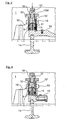
- einen nur teilweise dargestellten Ventiltrieb zur Betätigung zweier Auslassventile je Zylinder der Brennkraftmaschine über eine Ventilbrücke, wobei das Schrittschaltwerk gemäß
Fig. 2 in einen ortsfesten Gegenhalter integriert und in eine Grundstellung geschaltet ist, die einem regulären Motorbetrieb entspricht; und - Fig. 4
- den Ventiltrieb nach
Fig. 3 , wobei das Schrittschaltwerk in die einem Motorbremsbetrieb entsprechende Zwischenstellung des Auslassventils umgeschaltet ist. - Die
Fig. 1 zeigt in einem teilweisen Querschnitt einen vereinfacht dargestellten Zylinderkopf 1 einer turboaufgeladenen Diesel-Brennkraftmaschine für Kraftfahrzeuge, insbesondere Nutzkraftfahrzeuge, mit einer Nockenwelle 2, die über Nocken 3 sowohl Einlassventile als auch zumindest ein Auslassventil je Zylinder antreibt. Soweit nicht dargestellt kann der Ventiltrieb dazu in bekannter Weise ausgeführt sein. - Die Betätigung der Auslassventile (hier nicht eingezeichnet) erfolgt jeweils über die Nocken 3, die über Rollen 4 auf in einer Wand 1a des Zylinderkopfs 1 axial verschiebbar geführte Stößel 5 wirken. Die Stößel 5 beaufschlagen Rollen 6 von Kipphebeln 7, die auf einer ortsfesten Achse 8 im Zylinderkopf 1 schwenkbar gelagert sind und die in bekannter Weise die Auslassventile betätigen.
- In die Stößel 5 ist jeweils ein Schrittschaltwerk 9 integriert, das im Kraftfluss des Ventiltriebs liegend von einer Grundstellung entsprechend einer regulären Ventilbetätigung in eine Stellung umschaltbar ist, in der das oder die jeweiligen Auslassventil(e) in einer Zwischenstellung gehalten wird oder werden. In der Zwischenstellung sind die Auslassventile nicht geschlossen, sondern bilden einen Durchströmspalt zum Erzeugen einer Dekompressionswirkung im Motorbremsbetrieb.
- Die
Fig. 2 zeigt in Zusammenschau mit derFig. 1 skizzenhaft den Aufbau des Schrittschaltwerks 9 bzw. dessen Umschaltfunktion. Die wesentlichen Bauteile sind gebildet durch eine Führungshülse 10, einen kraftübertragenden Stern 11 und ein das Umschalten bewirkendes Stellglied 12. - Die Führungshülse 10 bildet hier beispielhaft teilegleich den Stößel 5 und trägt an der Unterseite die an den Nocken 3 anlaufende Rolle 4 (vgl.
Fig. 1 ). In die Führungshülse 10 sind einerseits zwischen und andererseits durch die radial nach innen ragenden, achsparallelen Stege 10a axial ausgerichtete Nuten 10b, 10c gebildet, die alternierend eine geringere Tiefe 10b und eine größere Tiefe 10c aufweisen. Beispielhaft folgt hier eine Nut 10b einer ersten, geringeren Tiefe jeweils auf eine Nut 10c einer demgegenüber zweiten, größeren Tiefe. - In diese Nuten 10b oder 10c ragen bzw. greifen dann je nach Schaltstellung des Schrittschaltwerks 9 radial nach außen gerichtete Arme, Zacken oder Stege 11 b des Sterns 11 ein, wobei die Anzahl der Stege 11 b des Sterns 11 gleich der Anzahl der Nuten 10b und der Anzahl der Nuten 10c in der Führungshülse 10 entspricht.
- Greifen die Stege 11 b des Sterns 11 in die tieferen Nuten 10c der Führungshülse 10 ein, so können die Auslassventile regulär schließen. Greifen die Stege 11 b in die weniger tiefen Nuten 10b ein, werden über den Stern 11 und den Kipphebel 7 die Auslassventile in einer definierten (geöffneten) Zwischenstellung gehalten, in der sie eine Dekompressionswirkung bei Motorbremsbetrieb erzeugen.
- Die Umschaltung der Positionen des Sterns 11 erfolgt über das innerhalb der Führungshülse 10 angeordnete, axial verschiebbar aber unverdrehbar geführte Stellglied 12, das stirnseitig eine Schrägverzahnung 12a aufweist, die an einer korrespondierenden Schrägverzahnung 11a des Sterns 11 anliegt. Wird das Stellglied 12 axial verschoben, so erzeugt es über die zusammenwirkenden Schrägverzahnungen 12a, 11a zunächst ein Drehmoment auf den Stern 11 und schiebt diesen zugleich aus den Nuten (10b oder 10c) heraus, bis der Eingriff in Umfangsrichtung durch die Stege 10a aufgehoben ist. Sodann kann sich der Stern 11 relativ zur Führungshülse 10 soweit verdrehen, bis die Stege 11 b des Sterns 11 in die jeweils benachbarten Nuten (10c oder 10b) einfahren können.
- Dies geschieht wie aus
Fig. 1 ersichtlich ist über einen in die Wand 1a des Zylinderkopfs 1 eingearbeiteten Zufuhrkanal 1 b, der in einen Druckraum 10d innerhalb der Führungshülse 10 mündet und über den das in der Führungshülse 10 geführte Stellglied 12 in Richtung auf den Stern 11 impulsförmig beaufschlagbar ist. - Eine an der Führungshülse 10 vorgesehene, an der Wand 1 a abgestützte Schraubendruckfeder 13 als beispielhaftes Vorspannelement hält dabei im drucklosen Zustand eine spielfreie Verbindung im Kraftfluss vom Nocken 3 über die Führungshülse 10 und den Stern 11 auf den Kipphebel 7 aufrecht. Der Zufuhrkanal 1 b ist in nicht dargestellter Weise über ein hydraulisches Steuerventil und ein dieses ansteuerndes, elektronisches Motorsteuergerät impulsförmig zum Umschalten des Schrittschaltwerks 9 beaufschlagbar.
- Die
Fig. 3 und 4 zeigen abschnittsweise einen an sich bekannten Ventiltrieb zum Betätigen je Zylinder der Brennkraftmaschine zwei Auslassventile 14 (es ist nur ein Auslassventil 14 und ohne Ventilfeder dargestellt), die über eine die Schäfte beider Auslassventile 14 überspannende Ventilbrücke 15 beaufschlagt sind. Funktionell gleiche Teile sind mit gleichen Bezugszeichen versehen. - Der Kraftfluss im Ventiltrieb erfolgt ähnlich der
Fig. 1 über die antreibende Nockenwelle 2 mit Nocken 3, die auf einen gemeinsamen Kipphebel 7 wirken, dessen freier Kipphebelarm mittig auf die Ventilbrücke 15 abtreibt und somit beide Auslassventile 14 betätigt. - Im Zylinderkopf 1 ist ortsfest ein Gegenhalter 16 befestigt, der die Ventilbrücke 15 im Bereich des einen, in eine Zwischenstellung steuerbaren Auslassventils 14 überragt.
- In den Gegenhalter 16 ist das in
Fig. 2 beschriebene Schrittschaltwerk 9 integriert, das zum Umschalten über einen hier oben liegenden Zufuhrkanal 17 in einer Anschlussschraube 18 hydraulisch beaufschlagbar ist. - Das Schrittschaltwerk 9 weist wiederum eine hier ortsfest in den Gegenhalter 16 eingeschraubte Führungshülse 10, den der Ventilbrücke 15 zugewandten Stern 11 und das in der Führungshülse 10 geführte Stellglied 12 auf, das an die Druckkammer 10d anschließt.
- Die Konstruktion des Schrittschaltwerks 9 ist analog der Konstruktion der
Fig. 2 mit dem Unterschied, dass die Bauteile in kinematischer Umkehrung angeordnet sind und im weiteren Sinne ebenfalls in den Kraftfluss des Ventiltriebs eingebunden sind. - Durch die Anordnung gemäß den
Fig. 3 und 4 bildet der nach unten ausgerichtete Stern 11 einen im Motorbremsbetrieb auf die Ventilbrücke 15 wirkenden Anschlag, der abgestützt über den Gegenhalter 16 das dargestellte Auslassventil 14 in der eine Dekompressionswirkung erzeugenden Zwischenstellung (Fig. 4 ) hält, während er im regulären, befeuerten Motorbetrieb (Fig. 3 ) wirkungslos eingefahren ist. - Die impulsförmige Umschaltung des Schrittschaltwerks 9 erfolgt hydraulisch wie vorbeschrieben und ist deshalb nicht weiter ausgeführt. Die Einstellung der Position des Schrittschaltwerks 9 kann wie dargestellt durch gezieltes Einschrauben der Führungshülse 10 in den Gegenhalter 16 und Festlegen mittels einer Kontermutter 19 erfolgen.
- Das Umschalten des Schrittschaltwerks 9 vom regulären, befeuerten Motorbetrieb auf Motorbremsbetrieb mit entsprechender Zwischenstellung der Auslassventile 14 kann hydraulisch zum Beispiel bei einem einen Motorbremsbetrieb signalisierenden Signal eines Steuergeräts und umgekehrt erfolgen. Gegebenenfalls kann das Umschalten dabei nicht hydraulisch, sondern elektromagnetisch durch Einbau einer entsprechenden elektromagnetischen Stelleinrichtung durchgeführt werden.
- Das Umschalten zum Einstellen einer Zwischenstellung des Auslassventils 14 kann auch beim Starten der Brennkraftmaschine und gegebenenfalls bei tiefen Außentemperaturen gesteuert sein, um deren Anspringen zu erleichtern (höhere Startdrehzahl).
- Gegebenenfalls kann das Schrittschaltwerk 9 auch so ausgeführt sein, dass mehrere Zwischenstellungen der Auslassventile 14 impulsförmig einstellbar sind, um die Dekompressionswirkung veränderlich zu steuern. Dabei müssten die Führungshülse 10 bzw. die Anzahl der Nuten 10b, 10c in der Führungshülse 10 ein Vielfaches der Stege 11 b des Sterns 11 betragen, um neben der Grundstellung (Motorbetrieb) weitere Zwischenstellungen bereitzustellen.
- Die elektronische Steuerung des Umschaltens des Schrittschaltwerks 9 kann bevorzugt eine feed back Steuerung sein, die den jeweiligen Schaltzustand des Schrittschaltwerks 9 anzeigt. Dies kann zum Beispiel mittels einer in das Schrittschaltwerk 9 integrierten Sensoranordnung bewerkstelligt sein.
- Die Schrittschaltwerke 9 des gesamten Ventiltriebs der Brennkraftmaschine können gegebenenfalls diskret angesteuert sein, so dass im Motorbremsbetrieb nur ein Zylinder oder mehrere Zylinder bzw. alle Zylinder in die dem Abgasrückstau überlagerbare Dekompressionswirkung umschaltbar sind.
-
1 Zylinderkopf 18 Anschlussschraube 1a Wand 19 Kontermutter 1b Zufuhrkanal 2 Nockenwelle 3 Nocken 4 Rolle 5 Stößel 6 Rolle 7 Kipphebel 8 Achse 9 Schrittschaltwerk 10 Führungshülse 10a Stege 10b, 10c Nuten 10d Druckraum 11 Stern 11a Schrägverzahnung 11b Stege 12 Stellglied 12a Schrägverzahnung 13 Feder 14 Auslassventil 15 Ventilbrücke 16 Gegenhalter 17 Zufuhrkanal
Claims (14)
- Vorrichtung zum Betätigen zumindest eines Auslassventils einer ventilgesteuerten Brennkraftmaschine für Kraftfahrzeuge, bei der, vorzugsweise im Kraftfluss zwischen einer Nockenwelle und wenigstens einem auf das Auslassventil wirkenden Betätigungselement, wenigstens ein Mittel vorgesehen ist, mittels dem das wenigstens eine Auslassventil, insbesondere bei einem Motorbremsbetrieb mit Abgasrückstau, in einer nicht geschlossenen Zwischenstellung haltbar ist, dadurch gekennzeichnet, dass das wenigstens eine Mittel durch ein in den Ventiltrieb integriertes Schrittschaltwerk (9) gebildet ist, das bei einer impulsartigen Betätigung zwischen einer regulären Ventilbetätigung und zumindest einer Zwischenstellung umschaltbar ist, insbesondere impulsartig umschaltbar ist.
- Vorrichtung nach Anspruch 1, dadurch gekennzeichnet, dass das Schrittschaltwerk (9) eine Führungshülse (10) mit unterschiedlich tiefen Längsnuten (10b, 10c), bevorzugt abwechselnd hintereinander angeordneten unterschiedlich tiefen Längsnuten (10b, 10c), einen in die Längsnuten (10b, 10c) eingreifenden, kraftübertragenden Stern (11) und ein mit dem Stern (11) über eine Drehmomentübertragungseinrichtung, insbesondere über eine Schrägverzahnung (12a, 11a), zusammenwirkendes, unverdrehbar in der Führungshülse (10) geführtes Stellglied (12) aufweist.
- Vorrichtung nach den Ansprüchen 2, dadurch gekennzeichnet, dass das Stellglied (12) mittels eines Vorspannelementes, insbesondere mittels einer Feder (13), gegen die verzahnte Stirnfläche (11a) des Sterns (11) axial vorgespannt ist.
- Vorrichtung nach einem der vorhergehenden Ansprüche, dadurch gekennzeichnet, dass das Schrittschaltwerk (9) in einen Stößel (5) des Ventiltriebs integriert ist.
- Vorrichtung nach einem der Ansprüche 2 bis 4, dadurch gekennzeichnet, dass die Führungshülse (10) an einem Nocken (3) der Nockenwelle (2) anläuft und der Stern (11) mittelbar oder unmittelbar auf das Auslassventil (14) abtreibt.
- Vorrichtung nach einem der Ansprüche 2 bis 5, dadurch gekennzeichnet, dass der Stern (11) auf einen in den Ventiltrieb integrierten Kipphebel (7) abtreibt.
- Vorrichtung nach einem der Ansprüche 2 bis 6, dadurch gekennzeichnet, dass zum Umschalten des Schrittschaltwerks (9) das Stellglied (12) mechanisch und/oder hydraulisch und/oder elektromagnetisch über ein Steuergerät impulsförmig beaufschlagt ist.
- Vorrichtung nach einem der vorhergehenden Ansprüche, dadurch gekennzeichnet, dass zwei Auslassventile (14) je Zylinder der Brennkraftmaschine über eine Ventilbrücke (15) gemeinsam betätigt werden, wobei einerseits der Ventilbrücke (15) ein ortsfester, in einer Anschlagstellung veränderlicher Gegenhalter (16) vorgesehen ist und wobei das Schrittschaltwerk (9) im Kraftfluss zwischen dem Gegenhalter (16) und der Ventilbrücke (15) angeordnet ist.
- Vorrichtung nach Anspruch 8, dadurch gekennzeichnet, dass das Schrittschaltwerk (9) in den Gegenhalter (16) integriert ist, wobei bevorzugt vorgesehen ist, dass eine Führungshülse (10) des Schrittschaltwerks (9) ortsfest angeordnet ist und ein Stern (11) des Schrittschaltwerks (9) den veränderlichen Anschlag für die Ventilbrücke (15) bildet.
- Vorrichtung nach einem der vorhergehenden Ansprüche, dadurch gekennzeichnet, dass über das Schrittschaltwerk (9) neben der Grundstellung (geschlossenes Auslassventil) mehrere Zwischenstellungen schaltbar sind, die impulsförmig über ein elektronisches Steuergerät mit feed-back-Steuerung ansteuerbar sind.
- Verfahren zum Betätigen zumindest eines Auslassventils einer ventilgesteuerten Brennkraftmaschine für Kraftfahrzeuge, insbesondere zum Betätigen einer Vorrichtung nach einem der vorhergehenden Ansprüche, bei der, vorzugsweise im Kraftfluss zwischen einer Nockenwelle und wenigstens einem auf das Auslassventil wirkenden Betätigungselement, wenigstens ein Mittel vorgesehen ist, mittels dem das wenigstens eine Auslassventil, insbesondere bei einem Motorbremsbetrieb mit Abgasrückstau, in einer nicht geschlossenen Zwischenstellung haltbar ist, dadurch gekennzeichnet, dass das wenigstens eine Mittel durch ein in den Ventiltrieb integriertes Schrittschaltwerk (9) gebildet ist, das bei einer impulsartigen Betätigung zwischen einer regulären Ventilbetätigung und zumindest einer Zwischenstellung umgeschaltet wird, insbesondere impulsartig umgeschaltet wird.
- Verfahren nach Anspruch 11, dadurch gekennzeichnet, dass bei einer Brennkraftmaschine mit mehreren Zylindern jeweils zumindest ein Auslassventil (14) über ein Schrittschaltwerk (9) im Motorbremsbetrieb offen gehalten wird und durch, insbesondere diskrete, Ansteuerung der Schrittschaltwerke (9) der Motorbremsbetrieb gezielt gesteuert wird.
- Verfahren nach Anspruch 11 oder 12, dadurch gekennzeichnet, dass über das Schrittschaltwerk (9) das Auslassventil (14) beim Starten der Brennkraftmaschine kurzzeitig offen gehalten wird.
- Kraftfahrzeug, insbesondere Nutzfahrzeug, mit einer Vorrichtung nach einem der vorhergehenden Ansprüche 1 bis 10, insbesondere zur Durchführung eines Verfahrens nach einem der Ansprüche 11 bis 13.
Applications Claiming Priority (1)
| Application Number | Priority Date | Filing Date | Title |
|---|---|---|---|
| DE102014001169.0A DE102014001169A1 (de) | 2014-01-31 | 2014-01-31 | Vorrichtung und Verfahren zum Betätigen zumindest eines Auslassventils einer ventilgesteuerten Brennkraftmaschine |
Publications (2)
| Publication Number | Publication Date |
|---|---|
| EP2902596A1 true EP2902596A1 (de) | 2015-08-05 |
| EP2902596B1 EP2902596B1 (de) | 2017-03-29 |
Family
ID=51790565
Family Applications (1)
| Application Number | Title | Priority Date | Filing Date |
|---|---|---|---|
| EP14003610.4A Active EP2902596B1 (de) | 2014-01-31 | 2014-10-23 | Vorrichtung und Verfahren zum Betätigen zumindest eines Auslassventils einer ventilgesteuerten Brennkraftmaschine |
Country Status (5)
| Country | Link |
|---|---|
| EP (1) | EP2902596B1 (de) |
| CN (1) | CN104819021B (de) |
| BR (1) | BR102014028290B1 (de) |
| DE (1) | DE102014001169A1 (de) |
| RU (1) | RU2680899C2 (de) |
Cited By (2)
| Publication number | Priority date | Publication date | Assignee | Title |
|---|---|---|---|---|
| WO2020088798A1 (en) * | 2018-11-01 | 2020-05-07 | Eaton Intelligent Power Limited | Bleeder type engine brake with hydraulic-mechanical actuation and lash adjustment |
| US11686224B2 (en) | 2019-06-20 | 2023-06-27 | Eaton Intelligent Power Limited | Cylinder deactivation and engine brake mechanism for type III center pivot valvetrains |
Families Citing this family (2)
| Publication number | Priority date | Publication date | Assignee | Title |
|---|---|---|---|---|
| DE102015015264A1 (de) * | 2015-11-26 | 2017-06-01 | Man Truck & Bus Ag | Variabler Ventiltrieb mit einem Kipphebel |
| US10774693B2 (en) * | 2018-10-04 | 2020-09-15 | Jacobs Vehicle Systems, Inc. | Variable length piston assemblies for engine valve actuation systems |
Citations (4)
| Publication number | Priority date | Publication date | Assignee | Title |
|---|---|---|---|---|
| WO1985003737A1 (en) * | 1984-02-20 | 1985-08-29 | Reginald John Hardy | Poppet valve drive |
| WO2009084598A1 (ja) * | 2007-12-27 | 2009-07-09 | Mitsubishi Fuso Truck And Bus Corporation | 内燃機関の可変動弁装置 |
| US20100319657A1 (en) | 2009-06-02 | 2010-12-23 | Jacobs Vehicle Systems, Inc. | Method and system for single exhaust valve bridge brake |
| US20130068195A1 (en) * | 2011-09-21 | 2013-03-21 | Jacobs Vehicle Systems, Inc. | Method and system for engine cylinder decompression |
Family Cites Families (3)
| Publication number | Priority date | Publication date | Assignee | Title |
|---|---|---|---|---|
| JP4423136B2 (ja) * | 2004-08-20 | 2010-03-03 | 日立オートモティブシステムズ株式会社 | 内燃機関の気筒停止制御装置 |
| JP5331343B2 (ja) * | 2007-12-27 | 2013-10-30 | ダイムラー・アクチェンゲゼルシャフト | 内燃機関の可変動弁装置 |
| DE102009048143A1 (de) * | 2009-10-02 | 2011-04-07 | Man Nutzfahrzeuge Aktiengesellschaft | Brennkraftmaschine mit einer Motorbremseinrichtung |
-
2014
- 2014-01-31 DE DE102014001169.0A patent/DE102014001169A1/de not_active Withdrawn
- 2014-10-23 EP EP14003610.4A patent/EP2902596B1/de active Active
- 2014-11-13 BR BR102014028290-4A patent/BR102014028290B1/pt active IP Right Grant
- 2014-12-15 RU RU2014150757A patent/RU2680899C2/ru active
-
2015
- 2015-02-02 CN CN201510052624.2A patent/CN104819021B/zh active Active
Patent Citations (4)
| Publication number | Priority date | Publication date | Assignee | Title |
|---|---|---|---|---|
| WO1985003737A1 (en) * | 1984-02-20 | 1985-08-29 | Reginald John Hardy | Poppet valve drive |
| WO2009084598A1 (ja) * | 2007-12-27 | 2009-07-09 | Mitsubishi Fuso Truck And Bus Corporation | 内燃機関の可変動弁装置 |
| US20100319657A1 (en) | 2009-06-02 | 2010-12-23 | Jacobs Vehicle Systems, Inc. | Method and system for single exhaust valve bridge brake |
| US20130068195A1 (en) * | 2011-09-21 | 2013-03-21 | Jacobs Vehicle Systems, Inc. | Method and system for engine cylinder decompression |
Cited By (3)
| Publication number | Priority date | Publication date | Assignee | Title |
|---|---|---|---|---|
| WO2020088798A1 (en) * | 2018-11-01 | 2020-05-07 | Eaton Intelligent Power Limited | Bleeder type engine brake with hydraulic-mechanical actuation and lash adjustment |
| US11686224B2 (en) | 2019-06-20 | 2023-06-27 | Eaton Intelligent Power Limited | Cylinder deactivation and engine brake mechanism for type III center pivot valvetrains |
| US11898470B2 (en) | 2019-06-20 | 2024-02-13 | Eaton Intelligent Power Limited | Cylinder deactivation and engine brake mechanism for type III center pivot valvetrains |
Also Published As
| Publication number | Publication date |
|---|---|
| DE102014001169A1 (de) | 2015-08-06 |
| RU2680899C2 (ru) | 2019-02-28 |
| RU2014150757A3 (de) | 2018-08-09 |
| BR102014028290A8 (pt) | 2021-08-24 |
| CN104819021B (zh) | 2018-12-25 |
| BR102014028290B1 (pt) | 2022-09-13 |
| EP2902596B1 (de) | 2017-03-29 |
| BR102014028290A2 (pt) | 2016-05-24 |
| CN104819021A (zh) | 2015-08-05 |
| RU2014150757A (ru) | 2016-07-10 |
Similar Documents
| Publication | Publication Date | Title |
|---|---|---|
| DE102004047395B4 (de) | Ventiltriebvorrichtung eines Verbrennungsmotors | |
| DE202015009047U1 (de) | Ventiltrieb für eine Brennkraftmaschine | |
| DE102011052912A1 (de) | Brennkraftmaschine und Ventiltrieb für eine Brennkraftmaschine | |
| DE102010004591A1 (de) | Gebauter Nockenträger für Ventiltrieb | |
| EP2902596B1 (de) | Vorrichtung und Verfahren zum Betätigen zumindest eines Auslassventils einer ventilgesteuerten Brennkraftmaschine | |
| EP2702253A1 (de) | Ventiltrieb für gaswechselventile einer brennkraftmaschine mit einer grundnockenwelle und zwischen drehlagern der grundnockenwelle in zwei oder mehr diskrete verschiebestellungen verschiebbaren nockenträgern | |
| EP3222828A2 (de) | Ventiltrieb für eine brennkraftmaschine | |
| EP2500533B1 (de) | Brennkraftmaschine mit gemischter Nockenwelle | |
| EP3332099B1 (de) | Ventiltrieb für eine brennkraftmaschine | |
| DE102011085706A1 (de) | Ventiltrieb einer Brennkraftmaschine | |
| DE102011085702A1 (de) | Ventiltrieb einer Brennkraftmaschine mit zumindest einem Schiebenockensystem | |
| EP3536917B1 (de) | Variabler ventiltrieb mit schiebenockensystem für eine brennkraftmaschine | |
| DE102016204892A1 (de) | Ventiltrieb für eine Brennkraftmaschine | |
| EP3221567B1 (de) | Ventiltrieb für eine brennkraftmaschine sowie entsprechende brennkraftmaschine | |
| EP3280886B1 (de) | Elektromagnetischer aktuator mit klemmfreien stoesseln | |
| EP3441581A1 (de) | Schiebenockensystem und verfahren zum betreiben eines verbrennungsmotors | |
| EP3173593B1 (de) | Variabler ventiltrieb mit einem kipphebel | |
| DE102011001124A1 (de) | Ventiltrieb für eine Brennkraftmaschine | |
| DE102012206552A1 (de) | Brennkraftmaschine für ein Kraftfahrzeug | |
| EP3450708A1 (de) | Schiebenockensystem | |
| DE102011085705A1 (de) | Ventiltrieb einer Brennkraftmaschine | |
| DE102017200203B4 (de) | Schiebestück mit Pumpennockensegment | |
| DE102007035305B4 (de) | Vorrichtung und Verfahren zur Ladungswechselsteuerung | |
| EP3564502B1 (de) | Variabler ventiltrieb | |
| DE102012214645A1 (de) | Brennkraftmaschine mit zwei gegenläufigen Nockenwellen |
Legal Events
| Date | Code | Title | Description |
|---|---|---|---|
| PUAI | Public reference made under article 153(3) epc to a published international application that has entered the european phase |
Free format text: ORIGINAL CODE: 0009012 |
|
| 17P | Request for examination filed |
Effective date: 20141023 |
|
| AK | Designated contracting states |
Kind code of ref document: A1 Designated state(s): AL AT BE BG CH CY CZ DE DK EE ES FI FR GB GR HR HU IE IS IT LI LT LU LV MC MK MT NL NO PL PT RO RS SE SI SK SM TR |
|
| AX | Request for extension of the european patent |
Extension state: BA ME |
|
| 17P | Request for examination filed |
Effective date: 20150912 |
|
| GRAP | Despatch of communication of intention to grant a patent |
Free format text: ORIGINAL CODE: EPIDOSNIGR1 |
|
| INTG | Intention to grant announced |
Effective date: 20170120 |
|
| GRAS | Grant fee paid |
Free format text: ORIGINAL CODE: EPIDOSNIGR3 |
|
| GRAA | (expected) grant |
Free format text: ORIGINAL CODE: 0009210 |
|
| AK | Designated contracting states |
Kind code of ref document: B1 Designated state(s): AL AT BE BG CH CY CZ DE DK EE ES FI FR GB GR HR HU IE IS IT LI LT LU LV MC MK MT NL NO PL PT RO RS SE SI SK SM TR |
|
| REG | Reference to a national code |
Ref country code: GB Ref legal event code: FG4D Free format text: NOT ENGLISH |
|
| REG | Reference to a national code |
Ref country code: CH Ref legal event code: EP |
|
| REG | Reference to a national code |
Ref country code: AT Ref legal event code: REF Ref document number: 879989 Country of ref document: AT Kind code of ref document: T Effective date: 20170415 |
|
| REG | Reference to a national code |
Ref country code: IE Ref legal event code: FG4D Free format text: LANGUAGE OF EP DOCUMENT: GERMAN |
|
| REG | Reference to a national code |
Ref country code: NL Ref legal event code: FP |
|
| REG | Reference to a national code |
Ref country code: DE Ref legal event code: R096 Ref document number: 502014003159 Country of ref document: DE |
|
| REG | Reference to a national code |
Ref country code: SE Ref legal event code: TRGR |
|
| PG25 | Lapsed in a contracting state [announced via postgrant information from national office to epo] |
Ref country code: GR Free format text: LAPSE BECAUSE OF FAILURE TO SUBMIT A TRANSLATION OF THE DESCRIPTION OR TO PAY THE FEE WITHIN THE PRESCRIBED TIME-LIMIT Effective date: 20170630 Ref country code: HR Free format text: LAPSE BECAUSE OF FAILURE TO SUBMIT A TRANSLATION OF THE DESCRIPTION OR TO PAY THE FEE WITHIN THE PRESCRIBED TIME-LIMIT Effective date: 20170329 Ref country code: NO Free format text: LAPSE BECAUSE OF FAILURE TO SUBMIT A TRANSLATION OF THE DESCRIPTION OR TO PAY THE FEE WITHIN THE PRESCRIBED TIME-LIMIT Effective date: 20170629 Ref country code: LT Free format text: LAPSE BECAUSE OF FAILURE TO SUBMIT A TRANSLATION OF THE DESCRIPTION OR TO PAY THE FEE WITHIN THE PRESCRIBED TIME-LIMIT Effective date: 20170329 Ref country code: FI Free format text: LAPSE BECAUSE OF FAILURE TO SUBMIT A TRANSLATION OF THE DESCRIPTION OR TO PAY THE FEE WITHIN THE PRESCRIBED TIME-LIMIT Effective date: 20170329 |
|
| PG25 | Lapsed in a contracting state [announced via postgrant information from national office to epo] |
Ref country code: RS Free format text: LAPSE BECAUSE OF FAILURE TO SUBMIT A TRANSLATION OF THE DESCRIPTION OR TO PAY THE FEE WITHIN THE PRESCRIBED TIME-LIMIT Effective date: 20170329 Ref country code: BG Free format text: LAPSE BECAUSE OF FAILURE TO SUBMIT A TRANSLATION OF THE DESCRIPTION OR TO PAY THE FEE WITHIN THE PRESCRIBED TIME-LIMIT Effective date: 20170629 Ref country code: LV Free format text: LAPSE BECAUSE OF FAILURE TO SUBMIT A TRANSLATION OF THE DESCRIPTION OR TO PAY THE FEE WITHIN THE PRESCRIBED TIME-LIMIT Effective date: 20170329 |
|
| PG25 | Lapsed in a contracting state [announced via postgrant information from national office to epo] |
Ref country code: CZ Free format text: LAPSE BECAUSE OF FAILURE TO SUBMIT A TRANSLATION OF THE DESCRIPTION OR TO PAY THE FEE WITHIN THE PRESCRIBED TIME-LIMIT Effective date: 20170329 Ref country code: EE Free format text: LAPSE BECAUSE OF FAILURE TO SUBMIT A TRANSLATION OF THE DESCRIPTION OR TO PAY THE FEE WITHIN THE PRESCRIBED TIME-LIMIT Effective date: 20170329 Ref country code: ES Free format text: LAPSE BECAUSE OF FAILURE TO SUBMIT A TRANSLATION OF THE DESCRIPTION OR TO PAY THE FEE WITHIN THE PRESCRIBED TIME-LIMIT Effective date: 20170329 Ref country code: SK Free format text: LAPSE BECAUSE OF FAILURE TO SUBMIT A TRANSLATION OF THE DESCRIPTION OR TO PAY THE FEE WITHIN THE PRESCRIBED TIME-LIMIT Effective date: 20170329 Ref country code: RO Free format text: LAPSE BECAUSE OF FAILURE TO SUBMIT A TRANSLATION OF THE DESCRIPTION OR TO PAY THE FEE WITHIN THE PRESCRIBED TIME-LIMIT Effective date: 20170329 |
|
| REG | Reference to a national code |
Ref country code: FR Ref legal event code: PLFP Year of fee payment: 4 |
|
| PG25 | Lapsed in a contracting state [announced via postgrant information from national office to epo] |
Ref country code: PL Free format text: LAPSE BECAUSE OF FAILURE TO SUBMIT A TRANSLATION OF THE DESCRIPTION OR TO PAY THE FEE WITHIN THE PRESCRIBED TIME-LIMIT Effective date: 20170329 Ref country code: PT Free format text: LAPSE BECAUSE OF FAILURE TO SUBMIT A TRANSLATION OF THE DESCRIPTION OR TO PAY THE FEE WITHIN THE PRESCRIBED TIME-LIMIT Effective date: 20170731 Ref country code: SM Free format text: LAPSE BECAUSE OF FAILURE TO SUBMIT A TRANSLATION OF THE DESCRIPTION OR TO PAY THE FEE WITHIN THE PRESCRIBED TIME-LIMIT Effective date: 20170329 Ref country code: IS Free format text: LAPSE BECAUSE OF FAILURE TO SUBMIT A TRANSLATION OF THE DESCRIPTION OR TO PAY THE FEE WITHIN THE PRESCRIBED TIME-LIMIT Effective date: 20170729 |
|
| REG | Reference to a national code |
Ref country code: DE Ref legal event code: R097 Ref document number: 502014003159 Country of ref document: DE |
|
| PG25 | Lapsed in a contracting state [announced via postgrant information from national office to epo] |
Ref country code: DK Free format text: LAPSE BECAUSE OF FAILURE TO SUBMIT A TRANSLATION OF THE DESCRIPTION OR TO PAY THE FEE WITHIN THE PRESCRIBED TIME-LIMIT Effective date: 20170329 |
|
| PLBE | No opposition filed within time limit |
Free format text: ORIGINAL CODE: 0009261 |
|
| STAA | Information on the status of an ep patent application or granted ep patent |
Free format text: STATUS: NO OPPOSITION FILED WITHIN TIME LIMIT |
|
| 26N | No opposition filed |
Effective date: 20180103 |
|
| PG25 | Lapsed in a contracting state [announced via postgrant information from national office to epo] |
Ref country code: SI Free format text: LAPSE BECAUSE OF FAILURE TO SUBMIT A TRANSLATION OF THE DESCRIPTION OR TO PAY THE FEE WITHIN THE PRESCRIBED TIME-LIMIT Effective date: 20170329 Ref country code: MC Free format text: LAPSE BECAUSE OF FAILURE TO SUBMIT A TRANSLATION OF THE DESCRIPTION OR TO PAY THE FEE WITHIN THE PRESCRIBED TIME-LIMIT Effective date: 20170329 |
|
| REG | Reference to a national code |
Ref country code: CH Ref legal event code: PL |
|
| REG | Reference to a national code |
Ref country code: IE Ref legal event code: MM4A |
|
| PG25 | Lapsed in a contracting state [announced via postgrant information from national office to epo] |
Ref country code: LI Free format text: LAPSE BECAUSE OF NON-PAYMENT OF DUE FEES Effective date: 20171031 Ref country code: CH Free format text: LAPSE BECAUSE OF NON-PAYMENT OF DUE FEES Effective date: 20171031 Ref country code: LU Free format text: LAPSE BECAUSE OF NON-PAYMENT OF DUE FEES Effective date: 20171023 |
|
| REG | Reference to a national code |
Ref country code: BE Ref legal event code: MM Effective date: 20171031 |
|
| PG25 | Lapsed in a contracting state [announced via postgrant information from national office to epo] |
Ref country code: BE Free format text: LAPSE BECAUSE OF NON-PAYMENT OF DUE FEES Effective date: 20171031 |
|
| PG25 | Lapsed in a contracting state [announced via postgrant information from national office to epo] |
Ref country code: MT Free format text: LAPSE BECAUSE OF FAILURE TO SUBMIT A TRANSLATION OF THE DESCRIPTION OR TO PAY THE FEE WITHIN THE PRESCRIBED TIME-LIMIT Effective date: 20170329 |
|
| REG | Reference to a national code |
Ref country code: FR Ref legal event code: PLFP Year of fee payment: 5 |
|
| PG25 | Lapsed in a contracting state [announced via postgrant information from national office to epo] |
Ref country code: IE Free format text: LAPSE BECAUSE OF NON-PAYMENT OF DUE FEES Effective date: 20171023 |
|
| GBPC | Gb: european patent ceased through non-payment of renewal fee |
Effective date: 20181023 |
|
| PG25 | Lapsed in a contracting state [announced via postgrant information from national office to epo] |
Ref country code: HU Free format text: LAPSE BECAUSE OF FAILURE TO SUBMIT A TRANSLATION OF THE DESCRIPTION OR TO PAY THE FEE WITHIN THE PRESCRIBED TIME-LIMIT; INVALID AB INITIO Effective date: 20141023 |
|
| REG | Reference to a national code |
Ref country code: DE Ref legal event code: R081 Ref document number: 502014003159 Country of ref document: DE Owner name: MAN TRUCK & BUS SE, DE Free format text: FORMER OWNER: MAN TRUCK & BUS AG, 80995 MUENCHEN, DE |
|
| PG25 | Lapsed in a contracting state [announced via postgrant information from national office to epo] |
Ref country code: CY Free format text: LAPSE BECAUSE OF FAILURE TO SUBMIT A TRANSLATION OF THE DESCRIPTION OR TO PAY THE FEE WITHIN THE PRESCRIBED TIME-LIMIT Effective date: 20170329 Ref country code: GB Free format text: LAPSE BECAUSE OF NON-PAYMENT OF DUE FEES Effective date: 20181023 |
|
| PG25 | Lapsed in a contracting state [announced via postgrant information from national office to epo] |
Ref country code: MK Free format text: LAPSE BECAUSE OF FAILURE TO SUBMIT A TRANSLATION OF THE DESCRIPTION OR TO PAY THE FEE WITHIN THE PRESCRIBED TIME-LIMIT Effective date: 20170329 |
|
| PG25 | Lapsed in a contracting state [announced via postgrant information from national office to epo] |
Ref country code: TR Free format text: LAPSE BECAUSE OF FAILURE TO SUBMIT A TRANSLATION OF THE DESCRIPTION OR TO PAY THE FEE WITHIN THE PRESCRIBED TIME-LIMIT Effective date: 20170329 |
|
| PG25 | Lapsed in a contracting state [announced via postgrant information from national office to epo] |
Ref country code: AL Free format text: LAPSE BECAUSE OF FAILURE TO SUBMIT A TRANSLATION OF THE DESCRIPTION OR TO PAY THE FEE WITHIN THE PRESCRIBED TIME-LIMIT Effective date: 20170329 |
|
| REG | Reference to a national code |
Ref country code: AT Ref legal event code: MM01 Ref document number: 879989 Country of ref document: AT Kind code of ref document: T Effective date: 20191023 |
|
| PG25 | Lapsed in a contracting state [announced via postgrant information from national office to epo] |
Ref country code: AT Free format text: LAPSE BECAUSE OF NON-PAYMENT OF DUE FEES Effective date: 20191023 |
|
| PGFP | Annual fee paid to national office [announced via postgrant information from national office to epo] |
Ref country code: NL Payment date: 20251024 Year of fee payment: 12 |
|
| PGFP | Annual fee paid to national office [announced via postgrant information from national office to epo] |
Ref country code: DE Payment date: 20251028 Year of fee payment: 12 |
|
| PGFP | Annual fee paid to national office [announced via postgrant information from national office to epo] |
Ref country code: IT Payment date: 20251022 Year of fee payment: 12 |
|
| PGFP | Annual fee paid to national office [announced via postgrant information from national office to epo] |
Ref country code: FR Payment date: 20251027 Year of fee payment: 12 |
|
| PGFP | Annual fee paid to national office [announced via postgrant information from national office to epo] |
Ref country code: SE Payment date: 20251024 Year of fee payment: 12 |