EP2902142A1 - Bohrer und verfahren zur herstellung geschnittener werkstücke damit - Google Patents
Bohrer und verfahren zur herstellung geschnittener werkstücke damit Download PDFInfo
- Publication number
- EP2902142A1 EP2902142A1 EP13842583.0A EP13842583A EP2902142A1 EP 2902142 A1 EP2902142 A1 EP 2902142A1 EP 13842583 A EP13842583 A EP 13842583A EP 2902142 A1 EP2902142 A1 EP 2902142A1
- Authority
- EP
- European Patent Office
- Prior art keywords
- cutting
- cutting section
- cutting edge
- edge
- drill
- Prior art date
- Legal status (The legal status is an assumption and is not a legal conclusion. Google has not performed a legal analysis and makes no representation as to the accuracy of the status listed.)
- Granted
Links
Images



Classifications
-
- B—PERFORMING OPERATIONS; TRANSPORTING
- B23—MACHINE TOOLS; METAL-WORKING NOT OTHERWISE PROVIDED FOR
- B23B—TURNING; BORING
- B23B51/00—Tools for drilling machines
- B23B51/02—Twist drills
-
- B—PERFORMING OPERATIONS; TRANSPORTING
- B23—MACHINE TOOLS; METAL-WORKING NOT OTHERWISE PROVIDED FOR
- B23B—TURNING; BORING
- B23B2251/00—Details of tools for drilling machines
- B23B2251/08—Side or plan views of cutting edges
- B23B2251/085—Discontinuous or interrupted cutting edges
-
- B—PERFORMING OPERATIONS; TRANSPORTING
- B23—MACHINE TOOLS; METAL-WORKING NOT OTHERWISE PROVIDED FOR
- B23B—TURNING; BORING
- B23B2251/00—Details of tools for drilling machines
- B23B2251/14—Configuration of the cutting part, i.e. the main cutting edges
-
- B—PERFORMING OPERATIONS; TRANSPORTING
- B23—MACHINE TOOLS; METAL-WORKING NOT OTHERWISE PROVIDED FOR
- B23B—TURNING; BORING
- B23B2251/00—Details of tools for drilling machines
- B23B2251/46—Drills having a centre free from cutting edges or with recessed cutting edges
-
- Y—GENERAL TAGGING OF NEW TECHNOLOGICAL DEVELOPMENTS; GENERAL TAGGING OF CROSS-SECTIONAL TECHNOLOGIES SPANNING OVER SEVERAL SECTIONS OF THE IPC; TECHNICAL SUBJECTS COVERED BY FORMER USPC CROSS-REFERENCE ART COLLECTIONS [XRACs] AND DIGESTS
- Y10—TECHNICAL SUBJECTS COVERED BY FORMER USPC
- Y10T—TECHNICAL SUBJECTS COVERED BY FORMER US CLASSIFICATION
- Y10T408/00—Cutting by use of rotating axially moving tool
- Y10T408/03—Processes
-
- Y—GENERAL TAGGING OF NEW TECHNOLOGICAL DEVELOPMENTS; GENERAL TAGGING OF CROSS-SECTIONAL TECHNOLOGIES SPANNING OVER SEVERAL SECTIONS OF THE IPC; TECHNICAL SUBJECTS COVERED BY FORMER USPC CROSS-REFERENCE ART COLLECTIONS [XRACs] AND DIGESTS
- Y10—TECHNICAL SUBJECTS COVERED BY FORMER USPC
- Y10T—TECHNICAL SUBJECTS COVERED BY FORMER US CLASSIFICATION
- Y10T408/00—Cutting by use of rotating axially moving tool
- Y10T408/89—Tool or Tool with support
- Y10T408/899—Having inversely angled cutting edge
-
- Y—GENERAL TAGGING OF NEW TECHNOLOGICAL DEVELOPMENTS; GENERAL TAGGING OF CROSS-SECTIONAL TECHNOLOGIES SPANNING OVER SEVERAL SECTIONS OF THE IPC; TECHNICAL SUBJECTS COVERED BY FORMER USPC CROSS-REFERENCE ART COLLECTIONS [XRACs] AND DIGESTS
- Y10—TECHNICAL SUBJECTS COVERED BY FORMER USPC
- Y10T—TECHNICAL SUBJECTS COVERED BY FORMER US CLASSIFICATION
- Y10T408/00—Cutting by use of rotating axially moving tool
- Y10T408/89—Tool or Tool with support
- Y10T408/905—Having stepped cutting edges
Definitions
- the present invention relates to a drill and a method for manufacturing cut workpieces using the same.
- Patent Literature 1 describes a drill having a concave arc-like shape, in a side view, at a front end portion of the body. The drill includes a cutting edge at the arc-like shaped portion.
- the drill starts to cut into a workpiece, which is an object to be cut, from an outermost periphery of the cutting edge.
- the end of the cutting edge comes into contact with the workpiece at a sharp angle. Therefore, the end of the cutting edge may easily chip when the cutting speed is high.
- problems such as chatter vibration or drill deflection may occur. This makes it difficult to improve roundness and positional accuracy of a drilled hole.
- a drill includes a cutting section having a cylindrical shape and configured to be rotated about a rotation axis.
- the cutting section includes a first cutting section and a second cutting section, at a front end portion thereof, a first flute continuous with the first cutting section and extending helically around the rotation axis toward a rear end of the cutting section, and a second flute continuous with the second cutting section and extending helically around the rotation axis toward the rear end of the cutting section.
- the first cutting section includes a first inner cutting edge extending from the rotation axis toward an outer peripheral surface and a first outer cutting edge positioned closer to the outer peripheral surface than the first inner cutting edge and gradually inclined to the rear end of the cutting section toward the outer peripheral surface.
- the second cutting section includes a second inner cutting edge extending from the rotation axis toward the outer peripheral surface and a second outer cutting edge positioned closer to the outer peripheral surface than the second inner cutting edge and gradually inclined to the rear end of the cutting section toward the outer peripheral surface.
- a distance from the rear end of the cutting section to an inner end of the first outer cutting edge in a rotation axis direction is equal to a distance from the rear end of the cutting section to an inner end of the second outer cutting edge.
- the first inner cutting edge is positioned closer to the rear end of the cutting section than the inner end of the first outer cutting edge
- the second inner cutting edge is positioned closer to the rear end of the cutting section than the inner end of the second outer cutting edge.
- the drill 1 of this embodiment includes a body 20, which is held by a spindle, for example, of a machine (not illustrated), and a cutting section 10 on one end side (front end side) of the body 20.
- a spindle for example, of a machine (not illustrated)
- a cutting section 10 on one end side (front end side) of the body 20.
- the spindle is not illustrated in Fig. 1
- the spindle is one component of the machine and rotates while holding the drill.
- the rotation of the spindle rotates the drill 1 about a rotation axis O.
- the body 20 is a portion that is designed in accordance with the shape of the rotation shaft of the machine.
- the cutting section 10 is a portion to be in contact with a work material.
- An arrow "a" indicates a rotational direction of the drill 1.
- the cutting section 10 is a crucial part for the cutting process of the work material.
- the cutting section 10 has a cylindrical shape and rotates about the rotation axis O.
- a front end portion 10a of the cutting section 10 includes a first cutting section 11A and a second cutting section 11B.
- the first cutting section 11A and the second cutting section 11B are rotationally symmetrical about the rotation axis 0 in a front end view. Due to this configuration, wobbling is unlikely to occur when the drill 1 bites into the work material. As a result, the drill 1 can perform stable drilling. Specifically, in a front end view, the first cutting section 11A and the second cutting section 11B are point-symmetrical with respect to the rotation axis 0 of the cutting section 10.
- the first cutting section 11A includes a first inner cutting edge 11a1 and a first outer cutting edge 11a.
- the first inner cutting edge 11a1 extends from the rotation axis O toward the outer peripheral surface.
- the first inner cutting edge 11a1 acts as a first chisel edge 11a1.
- the first outer cutting edge 11a is positioned closer to the outer peripheral surface than the first inner cutting edge 11a1 and is gradually inclined to a rear end 10b of the cutting section 10 toward the outer peripheral surface.
- the second cutting section 11B includes a second inner cutting edge 11b1 and a second outer cutting edge 11b.
- the second inner cutting edge 11b1 extends from the rotation axis 0 toward the outer peripheral surface.
- the second inner cutting edge 11b1 acts as a second chisel edge 11b1.
- the second outer cutting edge 11b is positioned closer to the outer peripheral surface than the second inner cutting edge 11b1 and is gradually inclined to the rear end 10b of the cutting section 10 toward the outer peripheral surface.
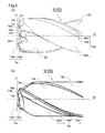
- first outer cutting edge 11a and the second outer cutting edge 11b are inclined as stated above, as illustrated in Fig. 4 , inner ends 11aa, 11ba of the first outer cutting edge 11a and the second outer cutting edge 11b come into contact with the work material before outer ends 11ab, 11bb of the first outer cutting edge 11a and the second outer cutting edge 11b.
- a distance from the rear end of the cutting section 10 to the inner end 11aa of the first outer cutting edge 11a in the direction along the rotation axis 0 is equal to a distance from the rear end of the cutting section 10 to the inner end 11ba of the second outer cutting edge 11b.
- the inner end 11aa of the first outer cutting edge 11a and the inner end 11ba of the second outer cutting edge 11b are both positioned on an imaginary line L1 that is perpendicular to the rotation axis O.
- the rigidity of the cutting section 10 is improved compared with the case in which the cutting edge comes into contact with the work material at the entire outer end.
- high chipping resistance is exhibited even when a cutting speed is high.
- first outer cutting edge 11a and second outer cutting edge 11b are positioned away from each other with the first chisel edge 11a1 and the second chisel edge 11b1, which are the first inner cutting edge 11a1 and the second inner cutting edge 11b1, being positioned therebetween.
- An exterior end (outer periphery) of the cutting section 10 includes two flutes (first flute 12a and second flute 12b) corresponding to the two outer cutting edges.
- the first flute 12a is continuous with the first cutting section 11A and extends helically around the rotation axis 0 from the front end portion 10a toward the rear end 10b of the cutting section 10.
- the second flute 12b is continuous with the second cutting section 11B and extends helically around the rotation axis 0 from the front end portion 10a toward the rear end 10b of the cutting section 10.
- the rotation axis 0 is a line passing through the center of the cutting section 10 in a front end view. In this embodiment, the rotation axis 0 passes through a point where the first chisel edge 11a1 and the second chisel edge 11b1 meet.
- the term "in a front end view” denotes that the drill 1 is viewed from a side of the front end portion 10a.
- the two chisel edges are included in the front end portion 10a of the cutting section 10.
- the first chisel edge 11a1 and the second chisel edge 11b1 cut the work material together with the first outer cutting edge 11a and the second outer cutting edge 11b.
- the first chisel edge 11a1 and the second chisel edge 11b1 are smoothly connected to each other at the rotation axis O.
- the first chisel edge 11a1 and the second chisel edge 11b1 are 180° rotationally symmetrical about the rotation axis 0 (axial line) of the cutting section 10.
- first chisel edge 11a1 and the second chisel edge 11b1 are smoothly connected to each other" denotes a state in which an inner end 11a1a of the first chisel edge 11a1 and an inner end 11b1a of the second chisel edge 11b1 share the tangent line in a front end view of the fire chisel edge 11a1 and the second chisel edge 11b1.
- the first chisel edge 11a1 and the second chisel edge 11b1 are curved in a front end view.
- the first chisel edge 11a1 is a convex curved line protruding toward the first flute 12a in a front end view.
- the second chisel edge 11b1 is a convex curved line protruding toward the second flute 12b in a front end view. This configuration enhances the strength of the first chisel edge 11a1 and the second chisel edge 11b1, and thus chipping of the chisel edges during the cutting process is reduced.
- the first inner cutting edge 11a1 (first chisel edge 11a1) is positioned closer to the rear end 10b of the cutting section 10 than the inner end 11aa of the first outer cutting edge 11a.
- the second inner cutting edge 11b1 (second chisel edge 11b1) is positioned closer to the rear end 10b of the cutting section 10 than the inner end 11ba of the second outer cutting edge 11b.
- the inner ends 11aa, 11ba of the two outer cutting edges protrude farthest in a direction along the front end of the cutting section 10.
- protrude farthest in the direction along the front end of the cutting section 10 denotes a state in which a distance from the rear end 10b of the cutting section 10 in the direction along the rotation axis 0 is the maximum.
- an imaginary line L2 perpendicular to the rotation axis 0 and in contact with the inner end 11a1a of the first inner cutting edge 11a1 and the inner end 11b1a of the second inner cutting edge 11b1 is positioned closer to the rear end of the cutting section 10 (on the right side in Fig. 4 ) than the imaginary line L1, which is in contact with the inner end 11aa of the first outer cutting edge 11a and the inner end 11ba of the second outer cutting edge 11b.
- first cutting section 11A and the second cutting section 11B have the above configuration, the inner end 11aa of the first outer cutting edge 11a and the inner end 11ba of the second outer cutting edge 11b come into contact with the work material before the first inner cutting edge 11a1 and the second inner cutting edge 11b1.
- burr is unlikely to occur in an inner wall of a drilled hole compared with a case in which the center of the entire cutting edge is the first to come into contact with the work material.
- the first outer cutting edge 11a and the second outer cutting edge 11b are 180° rotationally symmetrical about the rotation axis 0 (axial line) of the cutting section 10.
- the first outer cutting edge 11a of this embodiment in the front end view of Fig. 3 , includes a concave portion 11ac recessed from the first flute 12a and a convex portion 11ad protruding toward the first flute 12a.
- the convex portion 11ad is positioned closer to the outer periphery than the concave portion 11ac.
- the concave portion 11ac enables chips to be readily curled, which improves chip removal.
- the convex portion 11ad enhances the strength of the cutting edge at a part receiving a large cutting force.
- the concave portion 11ac and the convex portion 11ad are distinguished by the side in the rotational direction to which they protrude from a straight line connecting the inner end 11aa and the outer end 11ab of the first outer cutting edge 11a.
- the concave portion 11ac is positioned closer to the inner end 11aa and the convex portion 11ad is positioned closer to the outer end 11ab. If the concave portion 11ac and the convex portion 11ad form one continuous curved line, the strength of the first outer cutting edge 11a is further enhanced.
- the term “inner end” denotes an end portion, of a predetermined component, on a side closer to the rotation axis (center axis) 0 in a front end view.
- the term “outer end” denotes an end portion on a side far from the rotation axis O.
- the outer end 11a1b of the first chisel edge 11a1 is positioned behind the inner end 11aa of the first outer cutting edge 11a in the rotational direction in a front end view.
- the first chisel edge 11a1 is not continuous with the first outer cutting edge 11a. In other words, the first chisel edge 11a1 is away from the first outer cutting edge 11a.
- the first chisel edge 11a1 is not continuous with the first outer cutting edge 11a in a front end view. Furthermore, as illustrated in Fig. 4 , the first chisel edge 11a1 is not continuous with the first outer cutting edge 11a in a side view either. With this configuration, the first chisel edge 11a1 and the first outer cutting edge 11a start to bite into the work material at different times. Thus, a high chip-separation property is exhibited, and consistent chip ejection is achieved.
- the cutting section 10 includes flank surfaces 14, which are continuous with a corresponding one of the first cutting section 11A and the second cutting section 11B.
- the flank surfaces 14 each include a first flank surface 14a, which is continuous with the first outer cutting edge 11a or the second outer cutting edge 11b, and a second flank surface 14b, which is continuous with the first flank surface 14a, and a third flank surface 14c, which is continuous with the second flank surface 14b.
- the first flank surface 14a is inclined at 5 to 15°, for example, toward the rear end 10b with respect to the first outer cutting edge 11a or the second outer cutting edge 11b.
- the second flank surface 14b is inclined at 5 to 40°, for example, toward the rear end 10b with respect to the first flank surface 14a.
- the third flank surface 14c is inclined at 5 to 40° toward the rear end 10b with respect to the second flank surface 14b.
- the flank surfaces 14 each further include a fourth flank surface 14a1, which is continuous with the first chisel edge 11a1 or the second chisel edge 11b1, a fifth flank surface 14b1, which is continuous with the fourth flank surface 14a1, and a sixth flank surface 14c1, which is continuous with the fifth flank surface 14b1.
- the fourth flank surface 14a1 is inclined at 5 to 15°, for example, toward the rear end 10b with respect to the first chisel edge 11a1 or the second chisel edge 11b1.
- the fifth flank surface 14b1 is inclined at 5 to 40°, for example, toward the rear end 10b with respect to the fourth flank surface 14a1.
- the sixth flank surface 14c1 is inclined at 5 to 40°, for example, toward the rear end 10b with respect to the fifth flank surface 14b1.
- This embodiment includes the fourth flank surface 14a1 to the sixth flank surface 14c1 with respect to the first chisel edge 11a1.
- the flank surfaces 14a1 to 14c1 of the first chisel edge 11a1 are unlikely to be in contact with the work material. Thus, not only the cutting resistance, but also the damage to the first chisel edge 11a1 is reduced.
- the inner end 11aa of the first outer cutting edge 11a in a front end view protrudes farthest in a direction of the front end of the cutting section 10 in a side view.
- the inner end 11a1a of the first chisel edge 11a1 in a front end view and the outer end 11ab of the first outer cutting edge 11a in a front end view are located at different front-rear positions in a side view. If both ends come into contact with the work material at the same time, higher cutting resistance will result. In such a case, the outer end 11ab of the first outer cutting edge 11a can chip due to the vibration resulting from the increased cutting resistance. However, the above-described configuration reduces the possibility that the outer end 11ab of the first outer cutting edge 11a will chip.
- the outer end 11ab of the first outer cutting edge 11a in a front end view only has to be positioned closer to the rear end 10b in a side view than the inner end 11a1a of the first chisel edge 11a1 in a front end view, for example.
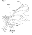
- the two flutes are configured mainly to eject chips produced by two outer cutting edges (first outer cutting edge 11a, second outer cutting edge 11b). As illustrated in Fig. 1 and Fig. 2 , the first flute 12a and the second flute 12b are continuous with the first outer cutting edge 11a and the second outer cutting edge 11b, respectively. Furthermore, the first flute 12a and the second flute 12b extend helically around the rotation axis 0 from the front end portion 10a of the cutting section 10 toward the rear end 10b.
- chips produced by the first outer cutting edge 11a are ejected to the side of the rear end 10b through the first flute 12a, which is continuous with the first outer cutting edge 11a.
- Chips produced by the second outer cutting edge 11b are ejected to the side of the rear end 10b through the second flute 12b, which is continuous with the second outer cutting edge 11b.
- the helix angle of the first flute 12a and the helix angle of the second flute 12b are the same. Furthermore, chips produced by the first inner cutting edge 11a1 and the second inner cutting edge 11b1 are ejected to the side of the rear end 10b through a corresponding one of the first flute 12a and the second flute 12b via the sixth flank surfaces 14c1, which are positioned ahead of a corresponding one of the inner cutting edges 11a1, 11b1 in the rotational direction.
- an outer peripheral portion 16 (first outer peripheral portion 16a, second outer peripheral portion 16b) are areas without the flutes 12a, 12b.
- the diameter (outer diameter) of the drill in these areas is unchanged from the diameter before the formation of the flutes 12a, 12b.
- the outer peripheral portion 16 is a portion substantially corresponding to an outer end (outer periphery) of the cutting section 10 in a cross-sectional view and the outer peripheral portion 16 has an arc-like shape.
- the first outer peripheral portion 16a is continuous with the outer end 11ab of the first outer cutting edge 11a and extends toward the second flute 12b along the outer end in a front end view. Due to this configuration, during the drilling process, the first outer peripheral portion 16a guides the drill 1 while being in contact with the inner wall of the drilled hole in the work material.
- the first outer peripheral portion 16a includes, in the following order, a first margin 16a1, a first connection surface 16a2, and a first clearance 16a3, which is an order of distance from the first outer cutting edge 11a.
- the first margin 16a1 is a part of the outer end.
- the first connection surface 16a2 is curved toward the inner side in a front end view.
- the first flank surface 16a3 extends toward the second outer cutting edge 11b while retaining a predetermined depth from the outer end to the inner side.
- the second outer peripheral portion 16b has a similar configuration and functions as the first outer peripheral portion 16a.
- the outer diameter of the cutting section 10 may be within a range of 6 mm to 42.5 mm, for example.
- Fig. 5(a) is a view illustrating a step of moving the drill 1 closer to the work material 30 in a Y direction.
- Fig. 5(b) is a step of bringing the drill 1 into contact with the work material 30.
- Fig. 5(c) is a view illustrating a step of moving the drill 1 away from the work material 30 in a Z direction.
- the method for manufacturing a cut workpiece according to this embodiment includes the following steps (i) to (iv).
- a step (i) the drill 1 is positioned over the prepared work material 30 (see Fig. 5(a) ).
- a step (ii) the drill 1 is rotated about the rotation axis 0 in the direction indicated by an arrow "a” and the drill 1 is moved closer to the work material 30 in the direction indicated by an arrow "Y" (see Figs. 5(a) and (b) ).
- This step may be performed by moving the rotating drill 1 closer to the work material 30 with the work material 30 being fixed onto the table of the machine including the drill 1, for example.
- the work material 30 and the drill 1 have only to come close to each other.
- the work material 30 may be moved closer to the drill 1 while the drill 1 is being fixed, for example.
- a step (iii) the drill 1 is further moved closer to the work material 30 such that the first cutting section 11A and the second cutting section 11B of the rotating drill 1 are brought into contact with a predetermined position of the surface of the work material 30.
- a drilled hole (through hole) 31 is formed in the work material 30 (see Figs. 5(b) and (c) ).
- an area which is positioned close to the rear end 10b, of the cutting section 10 of the drill 1, does not penetrate through the work material 30.
- this area is configured as a margin area for chip ejection to achieve a high chip ejection property.
- a step (iv) the drill 1 is moved in the direction indicated by an arrow "Z" so as to be away from the work material 30 (see Fig. 5(c) ).
- the work material 30 and the drill 1 only have to be away from each other.
- the work material 30 may be moved away from the drill 1 while the drill 1 is fixed, for example.
- the above-described drilling process may be performed to the work material 30 multiple times, for example, to form a plurality of drilled holes (through holes) 31 in the work material 30.
- a step of bringing the first outer cutting edge 11a and the second outer cutting edge 11b of the drill 1 into contact with the work material 30 may be repeated on different parts of the work material 30 while the drill 1 is being rotated.
- the drill 1 according to one embodiment of the present invention was described as an example.
- the present invention should not be limited to the above description, and may be implemented in any ways without departing from the spirit of the invention.
- the shape of the cutting section 10, for example, should not be limited to the configuration in the above-described embodiment and may be any shape widely used by a person skilled in the art.
- the cutting section 10, for example, may have a tapered shape in which a web thickness in an inscribed circle increases from the front end portion 10a toward the rear end 10b.
- the cutting section 10 may be inclined such that the diameter of the drill (outer diameter) increases or decreases from the front end portion 10a toward the rear end 10b.
- the cutting section 10 may have a so-called undercut or a clearance.
- first flute 12a and the second flute 12b have the equal flute width.
- first flute 12a and the second flute 12b each may have a larger flute diameter at a part in the front end portion 10a.
- first flute 12a and the second flute 12b may have a flute width that gradually increases or decreases from the front end portion 10a to the rear end 10b.
- first flute 12a and the second flute 12b may be different in flute length.
- the helix angle of one or both of the first flute 12a and the second flute 12b may be changed such that the first flute 12a and the second flute 12b are connected.
- the first inner cutting edge 11a1 is away from the first outer cutting edge 11a
- the second inner cutting edge 11b1 is away from the second outer cutting edge 11b.
- the first inner cutting edge 11a1 may be continuous with the first outer cutting edge 11a
- the second inner cutting edge 11b1 may be continuous with the second outer cutting edge 11b.
- the operational advantages same as in the drill 1 of the above-described embodiment are obtained, because the first inner cutting edge 11a1 (first chisel edge 11a1) is positioned closer to the rear end 10b of the cutting section 10 than the inner end 11aa of the first outer cutting edge 11a, and the second inner cutting edge 11b1 (second chisel edge 11b1) is positioned closer to the rear end 10b of the cutting section 10 than the inner end 11ba of the second outer cutting edge 11b. Furthermore, the first cutting section 11A as a whole has high rigidity, because the first inner cutting edge 11a1 is continuous with the first outer cutting edge 11a.
- the drill 1 including the cutting section 10 that is formed of a single member is described.
- a portion of the cutting section 10 including a front end may be detachable from a portion, of the cutting section 10, including the rear end 10b.
- the same operational advantages as in the drill 1 of the above-described embodiments are obtained.
Landscapes
- Engineering & Computer Science (AREA)
- Mechanical Engineering (AREA)
- Drilling Tools (AREA)
Applications Claiming Priority (2)
| Application Number | Priority Date | Filing Date | Title |
|---|---|---|---|
| JP2012217864 | 2012-09-28 | ||
| PCT/JP2013/075166 WO2014050661A1 (ja) | 2012-09-28 | 2013-09-18 | ドリルおよびそれを用いた切削加工物の製造方法 |
Publications (3)
| Publication Number | Publication Date |
|---|---|
| EP2902142A1 true EP2902142A1 (de) | 2015-08-05 |
| EP2902142A4 EP2902142A4 (de) | 2016-06-01 |
| EP2902142B1 EP2902142B1 (de) | 2021-01-06 |
Family
ID=50388066
Family Applications (1)
| Application Number | Title | Priority Date | Filing Date |
|---|---|---|---|
| EP13842583.0A Not-in-force EP2902142B1 (de) | 2012-09-28 | 2013-09-18 | Bohrer und verfahren zur herstellung geschnittener werkstücke damit |
Country Status (4)
| Country | Link |
|---|---|
| US (1) | US9662718B2 (de) |
| EP (1) | EP2902142B1 (de) |
| JP (1) | JP5898327B2 (de) |
| WO (1) | WO2014050661A1 (de) |
Families Citing this family (4)
| Publication number | Priority date | Publication date | Assignee | Title |
|---|---|---|---|---|
| US20160052072A1 (en) * | 2014-08-22 | 2016-02-25 | Kennametal lnc. | Asymmetric end mills and applications thereof |
| JP5967328B1 (ja) * | 2016-03-28 | 2016-08-10 | 株式会社タンガロイ | 穴あけ工具 |
| US11383309B2 (en) * | 2018-01-12 | 2022-07-12 | Kyocera Corporation | Cutting tool and method for manufacturing machined product |
| JP6714248B1 (ja) * | 2019-11-06 | 2020-06-24 | 株式会社ジーベックテクノロジー | 面取りカッターおよびワークの面取り方法 |
Family Cites Families (23)
| Publication number | Priority date | Publication date | Assignee | Title |
|---|---|---|---|---|
| US305625A (en) * | 1884-09-23 | Thomas newey | ||
| US2334089A (en) * | 1939-11-06 | 1943-11-09 | Erik E Hallden | Drill |
| US2259611A (en) * | 1941-03-19 | 1941-10-21 | George M Burger | Drill |
| US2898786A (en) * | 1955-12-14 | 1959-08-11 | John R Willingham | Blind hole drill |
| GB832238A (en) * | 1956-10-08 | 1960-04-06 | Rawlplug Co Ltd | Improvements in or relating to rotary masonry drills |
| US3452625A (en) * | 1966-11-21 | 1969-07-01 | Peter Russo | Drill |
| US4143723A (en) * | 1977-10-04 | 1979-03-13 | Schmotzer Norman H | Carbide tipped drill bit for boring holes in concrete and steel |
| JPS5943046Y2 (ja) * | 1980-12-08 | 1984-12-19 | トヨタ自動車株式会社 | チゼルレスシンニングドリル |
| JPS5981010A (ja) * | 1982-10-29 | 1984-05-10 | Nippon Oil & Fats Co Ltd | 穴明け工具 |
| DE3344620A1 (de) | 1983-12-09 | 1985-06-20 | Hartmetallwerkzeugfabrik Andreas Maier GmbH + Co KG, 7959 Schwendi | Mehrschneidenbohrer |
| JPH04101708A (ja) * | 1990-08-15 | 1992-04-03 | Masao Kubota | ドリル |
| JPH0929525A (ja) | 1995-07-20 | 1997-02-04 | Mizutani Seiki Kogyo Kk | ドリル |
| CH693228A5 (de) * | 1998-04-23 | 2003-04-30 | Micro Crystalag | Micro-Bohrer für die Leiterplattenfertigung mit 0.05bis 1,5 mm Durchmesser und mit zwei oder mehr Schneiden und zweioder mehr Bohrspitzen. |
| US6267542B1 (en) * | 1999-01-15 | 2001-07-31 | Avraham Salmon | Drill bit having a chiseless bit tip |
| SE522600C2 (sv) * | 2001-10-24 | 2004-02-24 | Seco Tools Ab | Borrverktyg för skärande bearbetning med tre skäreggar vid vilka tre spolkanaler mynnar |
| US20040018064A1 (en) * | 2002-03-15 | 2004-01-29 | Liu Chunghorng R. | Cutting tools |
| US6817429B2 (en) | 2002-10-03 | 2004-11-16 | Jimmie Sollami | Roof bit carbide blade |
| JP2004261930A (ja) * | 2003-03-03 | 2004-09-24 | Mitsubishi Materials Corp | ドリル |
| DE102004047469A1 (de) | 2004-09-30 | 2006-04-06 | Robert Bosch Gmbh | Bohrwerkzeug mit einem als Platte oder Kopf ausgebildeten Schneidelement |
| CN2820394Y (zh) * | 2005-09-14 | 2006-09-27 | 江苏天工工具股份有限公司 | 一种分屑强力钻 |
| SE532432C2 (sv) * | 2008-05-09 | 2010-01-19 | Sandvik Intellectual Property | Borrkropp med primära och sekundära släppningsytor |
| SE533855C2 (sv) * | 2009-06-23 | 2011-02-08 | Sandvik Intellectual Property | Roterbart verktyg för spånavskiljande bearbetning samt löstopp och grundkropp härför |
| CN102946820B (zh) * | 2010-04-22 | 2015-04-29 | 尼尔生物技术有限公司 | 钻头及具备该钻头的钻体 |
-
2013
- 2013-09-18 JP JP2014538420A patent/JP5898327B2/ja active Active
- 2013-09-18 US US14/431,308 patent/US9662718B2/en not_active Expired - Fee Related
- 2013-09-18 WO PCT/JP2013/075166 patent/WO2014050661A1/ja not_active Ceased
- 2013-09-18 EP EP13842583.0A patent/EP2902142B1/de not_active Not-in-force
Also Published As
| Publication number | Publication date |
|---|---|
| US20150266108A1 (en) | 2015-09-24 |
| WO2014050661A1 (ja) | 2014-04-03 |
| JP5898327B2 (ja) | 2016-04-06 |
| EP2902142A4 (de) | 2016-06-01 |
| JPWO2014050661A1 (ja) | 2016-08-22 |
| US9662718B2 (en) | 2017-05-30 |
| EP2902142B1 (de) | 2021-01-06 |
Similar Documents
| Publication | Publication Date | Title |
|---|---|---|
| JP5909565B2 (ja) | ドリルおよびそれを用いた切削加工物の製造方法 | |
| EP2990145B1 (de) | Bohrer und verfahren zur herstellung von schneideprodukten damit | |
| EP3040146A1 (de) | Fingerfräser mit kühlungslöchern | |
| JP2021059010A (ja) | 切削工具及び切削加工物の製造方法 | |
| JP5383149B2 (ja) | ドリルおよび切削方法 | |
| CN110446575B (zh) | 球头立铣刀 | |
| EP2902142B1 (de) | Bohrer und verfahren zur herstellung geschnittener werkstücke damit | |
| CN114641362B (zh) | 倒角刀以及工件的倒角方法 | |
| WO2011096511A1 (ja) | 刃先交換式溝入れ工具及び端面溝入れ加工方法 | |
| JP6941047B2 (ja) | 回転工具及び切削加工物の製造方法 | |
| JP6458851B1 (ja) | リーマ | |
| JP2013208692A (ja) | ドリル及びそれを用いた切削加工物の製造方法 | |
| KR102027299B1 (ko) | 탄소복합소재 가공 형상 드릴 | |
| JP2016147328A (ja) | ドリル | |
| EP1439019B1 (de) | Bohrer | |
| JP5845288B2 (ja) | ドリルおよびそれを用いた切削加工物の製造方法 | |
| JP6110496B2 (ja) | ドリルおよびそれを用いた切削加工物の製造方法 | |
| JP2013035101A (ja) | リーマ | |
| JP4666282B2 (ja) | ドリル | |
| JP5319928B2 (ja) | ボーリング工具及び孔開け加工方法 | |
| JP5471538B2 (ja) | 刃先交換式溝入れ工具及び端面溝入れ加工方法 | |
| JP5988353B2 (ja) | ドリル及びそれを用いた切削加工物の製造方法 | |
| JP2014079814A (ja) | 穴加工工具 | |
| JP2007021610A (ja) | テーパ刃エンドミルおよびそれを用いたテーパ穴形成方法 | |
| JP2008161999A (ja) | 切削工具 |
Legal Events
| Date | Code | Title | Description |
|---|---|---|---|
| PUAI | Public reference made under article 153(3) epc to a published international application that has entered the european phase |
Free format text: ORIGINAL CODE: 0009012 |
|
| 17P | Request for examination filed |
Effective date: 20150320 |
|
| AK | Designated contracting states |
Kind code of ref document: A1 Designated state(s): AL AT BE BG CH CY CZ DE DK EE ES FI FR GB GR HR HU IE IS IT LI LT LU LV MC MK MT NL NO PL PT RO RS SE SI SK SM TR |
|
| AX | Request for extension of the european patent |
Extension state: BA ME |
|
| DAX | Request for extension of the european patent (deleted) | ||
| REG | Reference to a national code |
Ref country code: DE Ref legal event code: R079 Ref document number: 602013075211 Country of ref document: DE Free format text: PREVIOUS MAIN CLASS: B23B0051000000 Ipc: B23B0051020000 |
|
| RA4 | Supplementary search report drawn up and despatched (corrected) |
Effective date: 20160503 |
|
| RIC1 | Information provided on ipc code assigned before grant |
Ipc: B23B 51/02 20060101AFI20160426BHEP |
|
| STAA | Information on the status of an ep patent application or granted ep patent |
Free format text: STATUS: EXAMINATION IS IN PROGRESS |
|
| 17Q | First examination report despatched |
Effective date: 20190402 |
|
| GRAP | Despatch of communication of intention to grant a patent |
Free format text: ORIGINAL CODE: EPIDOSNIGR1 |
|
| STAA | Information on the status of an ep patent application or granted ep patent |
Free format text: STATUS: GRANT OF PATENT IS INTENDED |
|
| INTG | Intention to grant announced |
Effective date: 20200827 |
|
| RIN1 | Information on inventor provided before grant (corrected) |
Inventor name: KOGA, KENICHIROU |
|
| GRAS | Grant fee paid |
Free format text: ORIGINAL CODE: EPIDOSNIGR3 |
|
| GRAA | (expected) grant |
Free format text: ORIGINAL CODE: 0009210 |
|
| STAA | Information on the status of an ep patent application or granted ep patent |
Free format text: STATUS: THE PATENT HAS BEEN GRANTED |
|
| AK | Designated contracting states |
Kind code of ref document: B1 Designated state(s): AL AT BE BG CH CY CZ DE DK EE ES FI FR GB GR HR HU IE IS IT LI LT LU LV MC MK MT NL NO PL PT RO RS SE SI SK SM TR |
|
| REG | Reference to a national code |
Ref country code: GB Ref legal event code: FG4D |
|
| REG | Reference to a national code |
Ref country code: AT Ref legal event code: REF Ref document number: 1351826 Country of ref document: AT Kind code of ref document: T Effective date: 20210115 Ref country code: CH Ref legal event code: EP |
|
| REG | Reference to a national code |
Ref country code: DE Ref legal event code: R096 Ref document number: 602013075211 Country of ref document: DE |
|
| REG | Reference to a national code |
Ref country code: IE Ref legal event code: FG4D |
|
| REG | Reference to a national code |
Ref country code: NL Ref legal event code: MP Effective date: 20210106 |
|
| REG | Reference to a national code |
Ref country code: AT Ref legal event code: MK05 Ref document number: 1351826 Country of ref document: AT Kind code of ref document: T Effective date: 20210106 |
|
| REG | Reference to a national code |
Ref country code: LT Ref legal event code: MG9D |
|
| PG25 | Lapsed in a contracting state [announced via postgrant information from national office to epo] |
Ref country code: GR Free format text: LAPSE BECAUSE OF FAILURE TO SUBMIT A TRANSLATION OF THE DESCRIPTION OR TO PAY THE FEE WITHIN THE PRESCRIBED TIME-LIMIT Effective date: 20210407 Ref country code: FI Free format text: LAPSE BECAUSE OF FAILURE TO SUBMIT A TRANSLATION OF THE DESCRIPTION OR TO PAY THE FEE WITHIN THE PRESCRIBED TIME-LIMIT Effective date: 20210106 Ref country code: HR Free format text: LAPSE BECAUSE OF FAILURE TO SUBMIT A TRANSLATION OF THE DESCRIPTION OR TO PAY THE FEE WITHIN THE PRESCRIBED TIME-LIMIT Effective date: 20210106 Ref country code: PT Free format text: LAPSE BECAUSE OF FAILURE TO SUBMIT A TRANSLATION OF THE DESCRIPTION OR TO PAY THE FEE WITHIN THE PRESCRIBED TIME-LIMIT Effective date: 20210506 Ref country code: LT Free format text: LAPSE BECAUSE OF FAILURE TO SUBMIT A TRANSLATION OF THE DESCRIPTION OR TO PAY THE FEE WITHIN THE PRESCRIBED TIME-LIMIT Effective date: 20210106 Ref country code: NL Free format text: LAPSE BECAUSE OF FAILURE TO SUBMIT A TRANSLATION OF THE DESCRIPTION OR TO PAY THE FEE WITHIN THE PRESCRIBED TIME-LIMIT Effective date: 20210106 Ref country code: NO Free format text: LAPSE BECAUSE OF FAILURE TO SUBMIT A TRANSLATION OF THE DESCRIPTION OR TO PAY THE FEE WITHIN THE PRESCRIBED TIME-LIMIT Effective date: 20210406 Ref country code: BG Free format text: LAPSE BECAUSE OF FAILURE TO SUBMIT A TRANSLATION OF THE DESCRIPTION OR TO PAY THE FEE WITHIN THE PRESCRIBED TIME-LIMIT Effective date: 20210406 |
|
| PG25 | Lapsed in a contracting state [announced via postgrant information from national office to epo] |
Ref country code: SE Free format text: LAPSE BECAUSE OF FAILURE TO SUBMIT A TRANSLATION OF THE DESCRIPTION OR TO PAY THE FEE WITHIN THE PRESCRIBED TIME-LIMIT Effective date: 20210106 Ref country code: AT Free format text: LAPSE BECAUSE OF FAILURE TO SUBMIT A TRANSLATION OF THE DESCRIPTION OR TO PAY THE FEE WITHIN THE PRESCRIBED TIME-LIMIT Effective date: 20210106 Ref country code: PL Free format text: LAPSE BECAUSE OF FAILURE TO SUBMIT A TRANSLATION OF THE DESCRIPTION OR TO PAY THE FEE WITHIN THE PRESCRIBED TIME-LIMIT Effective date: 20210106 Ref country code: LV Free format text: LAPSE BECAUSE OF FAILURE TO SUBMIT A TRANSLATION OF THE DESCRIPTION OR TO PAY THE FEE WITHIN THE PRESCRIBED TIME-LIMIT Effective date: 20210106 Ref country code: RS Free format text: LAPSE BECAUSE OF FAILURE TO SUBMIT A TRANSLATION OF THE DESCRIPTION OR TO PAY THE FEE WITHIN THE PRESCRIBED TIME-LIMIT Effective date: 20210106 |
|
| PG25 | Lapsed in a contracting state [announced via postgrant information from national office to epo] |
Ref country code: IS Free format text: LAPSE BECAUSE OF FAILURE TO SUBMIT A TRANSLATION OF THE DESCRIPTION OR TO PAY THE FEE WITHIN THE PRESCRIBED TIME-LIMIT Effective date: 20210506 |
|
| REG | Reference to a national code |
Ref country code: DE Ref legal event code: R097 Ref document number: 602013075211 Country of ref document: DE |
|
| PG25 | Lapsed in a contracting state [announced via postgrant information from national office to epo] |
Ref country code: SM Free format text: LAPSE BECAUSE OF FAILURE TO SUBMIT A TRANSLATION OF THE DESCRIPTION OR TO PAY THE FEE WITHIN THE PRESCRIBED TIME-LIMIT Effective date: 20210106 Ref country code: CZ Free format text: LAPSE BECAUSE OF FAILURE TO SUBMIT A TRANSLATION OF THE DESCRIPTION OR TO PAY THE FEE WITHIN THE PRESCRIBED TIME-LIMIT Effective date: 20210106 Ref country code: EE Free format text: LAPSE BECAUSE OF FAILURE TO SUBMIT A TRANSLATION OF THE DESCRIPTION OR TO PAY THE FEE WITHIN THE PRESCRIBED TIME-LIMIT Effective date: 20210106 |
|
| PLBE | No opposition filed within time limit |
Free format text: ORIGINAL CODE: 0009261 |
|
| STAA | Information on the status of an ep patent application or granted ep patent |
Free format text: STATUS: NO OPPOSITION FILED WITHIN TIME LIMIT |
|
| PG25 | Lapsed in a contracting state [announced via postgrant information from national office to epo] |
Ref country code: DK Free format text: LAPSE BECAUSE OF FAILURE TO SUBMIT A TRANSLATION OF THE DESCRIPTION OR TO PAY THE FEE WITHIN THE PRESCRIBED TIME-LIMIT Effective date: 20210106 Ref country code: ES Free format text: LAPSE BECAUSE OF FAILURE TO SUBMIT A TRANSLATION OF THE DESCRIPTION OR TO PAY THE FEE WITHIN THE PRESCRIBED TIME-LIMIT Effective date: 20210106 Ref country code: SK Free format text: LAPSE BECAUSE OF FAILURE TO SUBMIT A TRANSLATION OF THE DESCRIPTION OR TO PAY THE FEE WITHIN THE PRESCRIBED TIME-LIMIT Effective date: 20210106 Ref country code: RO Free format text: LAPSE BECAUSE OF FAILURE TO SUBMIT A TRANSLATION OF THE DESCRIPTION OR TO PAY THE FEE WITHIN THE PRESCRIBED TIME-LIMIT Effective date: 20210106 |
|
| 26N | No opposition filed |
Effective date: 20211007 |
|
| PG25 | Lapsed in a contracting state [announced via postgrant information from national office to epo] |
Ref country code: AL Free format text: LAPSE BECAUSE OF FAILURE TO SUBMIT A TRANSLATION OF THE DESCRIPTION OR TO PAY THE FEE WITHIN THE PRESCRIBED TIME-LIMIT Effective date: 20210106 |
|
| PG25 | Lapsed in a contracting state [announced via postgrant information from national office to epo] |
Ref country code: SI Free format text: LAPSE BECAUSE OF FAILURE TO SUBMIT A TRANSLATION OF THE DESCRIPTION OR TO PAY THE FEE WITHIN THE PRESCRIBED TIME-LIMIT Effective date: 20210106 |
|
| PG25 | Lapsed in a contracting state [announced via postgrant information from national office to epo] |
Ref country code: IT Free format text: LAPSE BECAUSE OF FAILURE TO SUBMIT A TRANSLATION OF THE DESCRIPTION OR TO PAY THE FEE WITHIN THE PRESCRIBED TIME-LIMIT Effective date: 20210106 |
|
| REG | Reference to a national code |
Ref country code: CH Ref legal event code: PL |
|
| REG | Reference to a national code |
Ref country code: BE Ref legal event code: MM Effective date: 20210930 |
|
| GBPC | Gb: european patent ceased through non-payment of renewal fee |
Effective date: 20210918 |
|
| PG25 | Lapsed in a contracting state [announced via postgrant information from national office to epo] |
Ref country code: IS Free format text: LAPSE BECAUSE OF FAILURE TO SUBMIT A TRANSLATION OF THE DESCRIPTION OR TO PAY THE FEE WITHIN THE PRESCRIBED TIME-LIMIT Effective date: 20210506 Ref country code: MC Free format text: LAPSE BECAUSE OF FAILURE TO SUBMIT A TRANSLATION OF THE DESCRIPTION OR TO PAY THE FEE WITHIN THE PRESCRIBED TIME-LIMIT Effective date: 20210106 |
|
| PG25 | Lapsed in a contracting state [announced via postgrant information from national office to epo] |
Ref country code: LU Free format text: LAPSE BECAUSE OF NON-PAYMENT OF DUE FEES Effective date: 20210918 Ref country code: IE Free format text: LAPSE BECAUSE OF NON-PAYMENT OF DUE FEES Effective date: 20210918 Ref country code: GB Free format text: LAPSE BECAUSE OF NON-PAYMENT OF DUE FEES Effective date: 20210918 Ref country code: FR Free format text: LAPSE BECAUSE OF NON-PAYMENT OF DUE FEES Effective date: 20210930 Ref country code: BE Free format text: LAPSE BECAUSE OF NON-PAYMENT OF DUE FEES Effective date: 20210930 |
|
| PG25 | Lapsed in a contracting state [announced via postgrant information from national office to epo] |
Ref country code: LI Free format text: LAPSE BECAUSE OF NON-PAYMENT OF DUE FEES Effective date: 20210930 Ref country code: CH Free format text: LAPSE BECAUSE OF NON-PAYMENT OF DUE FEES Effective date: 20210930 |
|
| PG25 | Lapsed in a contracting state [announced via postgrant information from national office to epo] |
Ref country code: HU Free format text: LAPSE BECAUSE OF FAILURE TO SUBMIT A TRANSLATION OF THE DESCRIPTION OR TO PAY THE FEE WITHIN THE PRESCRIBED TIME-LIMIT; INVALID AB INITIO Effective date: 20130918 |
|
| P01 | Opt-out of the competence of the unified patent court (upc) registered |
Effective date: 20230508 |
|
| PG25 | Lapsed in a contracting state [announced via postgrant information from national office to epo] |
Ref country code: CY Free format text: LAPSE BECAUSE OF FAILURE TO SUBMIT A TRANSLATION OF THE DESCRIPTION OR TO PAY THE FEE WITHIN THE PRESCRIBED TIME-LIMIT Effective date: 20210106 |
|
| PGFP | Annual fee paid to national office [announced via postgrant information from national office to epo] |
Ref country code: DE Payment date: 20230802 Year of fee payment: 11 |
|
| PG25 | Lapsed in a contracting state [announced via postgrant information from national office to epo] |
Ref country code: MK Free format text: LAPSE BECAUSE OF FAILURE TO SUBMIT A TRANSLATION OF THE DESCRIPTION OR TO PAY THE FEE WITHIN THE PRESCRIBED TIME-LIMIT Effective date: 20210106 |
|
| PG25 | Lapsed in a contracting state [announced via postgrant information from national office to epo] |
Ref country code: MT Free format text: LAPSE BECAUSE OF FAILURE TO SUBMIT A TRANSLATION OF THE DESCRIPTION OR TO PAY THE FEE WITHIN THE PRESCRIBED TIME-LIMIT Effective date: 20210106 |
|
| REG | Reference to a national code |
Ref country code: DE Ref legal event code: R119 Ref document number: 602013075211 Country of ref document: DE |
|
| PG25 | Lapsed in a contracting state [announced via postgrant information from national office to epo] |
Ref country code: DE Free format text: LAPSE BECAUSE OF NON-PAYMENT OF DUE FEES Effective date: 20250401 |
|
| PG25 | Lapsed in a contracting state [announced via postgrant information from national office to epo] |
Ref country code: TR Free format text: LAPSE BECAUSE OF FAILURE TO SUBMIT A TRANSLATION OF THE DESCRIPTION OR TO PAY THE FEE WITHIN THE PRESCRIBED TIME-LIMIT Effective date: 20210106 |