EP2901060B1 - Selbstausrichtender ventilstecker - Google Patents
Selbstausrichtender ventilstecker Download PDFInfo
- Publication number
- EP2901060B1 EP2901060B1 EP13774336.5A EP13774336A EP2901060B1 EP 2901060 B1 EP2901060 B1 EP 2901060B1 EP 13774336 A EP13774336 A EP 13774336A EP 2901060 B1 EP2901060 B1 EP 2901060B1
- Authority
- EP
- European Patent Office
- Prior art keywords
- valve
- valve plug
- self
- aligning
- retainer
- Prior art date
- Legal status (The legal status is an assumption and is not a legal conclusion. Google has not performed a legal analysis and makes no representation as to the accuracy of the status listed.)
- Active
Links
Images


Classifications
-
- F—MECHANICAL ENGINEERING; LIGHTING; HEATING; WEAPONS; BLASTING
- F16—ENGINEERING ELEMENTS AND UNITS; GENERAL MEASURES FOR PRODUCING AND MAINTAINING EFFECTIVE FUNCTIONING OF MACHINES OR INSTALLATIONS; THERMAL INSULATION IN GENERAL
- F16K—VALVES; TAPS; COCKS; ACTUATING-FLOATS; DEVICES FOR VENTING OR AERATING
- F16K1/00—Lift valves or globe valves, i.e. cut-off apparatus with closure members having at least a component of their opening and closing motion perpendicular to the closing faces
- F16K1/32—Details
- F16K1/34—Cutting-off parts, e.g. valve members, seats
- F16K1/36—Valve members
-
- F—MECHANICAL ENGINEERING; LIGHTING; HEATING; WEAPONS; BLASTING
- F16—ENGINEERING ELEMENTS AND UNITS; GENERAL MEASURES FOR PRODUCING AND MAINTAINING EFFECTIVE FUNCTIONING OF MACHINES OR INSTALLATIONS; THERMAL INSULATION IN GENERAL
- F16K—VALVES; TAPS; COCKS; ACTUATING-FLOATS; DEVICES FOR VENTING OR AERATING
- F16K31/00—Actuating devices; Operating means; Releasing devices
- F16K31/12—Actuating devices; Operating means; Releasing devices actuated by fluid
- F16K31/16—Actuating devices; Operating means; Releasing devices actuated by fluid with a mechanism, other than pulling-or pushing-rod, between fluid motor and closure member
- F16K31/165—Actuating devices; Operating means; Releasing devices actuated by fluid with a mechanism, other than pulling-or pushing-rod, between fluid motor and closure member the fluid acting on a diaphragm
-
- G—PHYSICS
- G05—CONTROLLING; REGULATING
- G05D—SYSTEMS FOR CONTROLLING OR REGULATING NON-ELECTRIC VARIABLES
- G05D16/00—Control of fluid pressure
- G05D16/04—Control of fluid pressure without auxiliary power
- G05D16/06—Control of fluid pressure without auxiliary power the sensing element being a flexible membrane, yielding to pressure, e.g. diaphragm, bellows, capsule
- G05D16/063—Control of fluid pressure without auxiliary power the sensing element being a flexible membrane, yielding to pressure, e.g. diaphragm, bellows, capsule the sensing element being a membrane
- G05D16/0675—Control of fluid pressure without auxiliary power the sensing element being a flexible membrane, yielding to pressure, e.g. diaphragm, bellows, capsule the sensing element being a membrane the membrane acting on the obturator through a lever
- G05D16/0694—Control of fluid pressure without auxiliary power the sensing element being a flexible membrane, yielding to pressure, e.g. diaphragm, bellows, capsule the sensing element being a membrane the membrane acting on the obturator through a lever using a spring-loaded membrane with a spring-loaded slideable obturator
-
- F—MECHANICAL ENGINEERING; LIGHTING; HEATING; WEAPONS; BLASTING
- F16—ENGINEERING ELEMENTS AND UNITS; GENERAL MEASURES FOR PRODUCING AND MAINTAINING EFFECTIVE FUNCTIONING OF MACHINES OR INSTALLATIONS; THERMAL INSULATION IN GENERAL
- F16K—VALVES; TAPS; COCKS; ACTUATING-FLOATS; DEVICES FOR VENTING OR AERATING
- F16K31/00—Actuating devices; Operating means; Releasing devices
Definitions
- the present disclosure relates to balanced pressure regulators, and more particularly, to a self-aligning valve plug for a balanced pressure regulator.
- Pressure regulating valves are used in myriad industrial and residential applications for controlling the downstream pressure of a fluid.
- pressure regulating valves are used to manipulate a flowing fluid to compensate for increases or decreases in demand, or other load disturbances, and thus keep the fluid pressure regulated.
- pressure regulating valves may be used in plumbing fixtures to maintain a pre-determined pressure of fluid that automatically adjusts to variations in demand, such as anti-scald valves in showers or faucets.
- pressure regulating valves compensate for variations in downstream demand. For example, as downstream demand increases, pressure regulating valves open to allow more fluid to flow through the pressure regulating valve, thus maintaining a relatively constant downstream pressure. On the other hand, as downstream demand decreases, pressure regulating valves close to reduce the amount of fluid flowing through the pressure regulating valve, again maintaining a relatively constant downstream pressure.
- Pressure regulating valves can be categorized as either balanced or unbalanced.
- Unbalanced valves typically have high pressure inlet fluid on one side of the valve plug and lower pressure outlet fluid on the other side of the valve plug.
- Unbalanced valves suffer from an undesirable effect known as decaying inlet characteristic.
- the decaying inlet characteristic is a phenomenon in which an unbalanced valve experiences an unintended increase in downstream pressure as the upstream pressure decreases. This effect is undesirable as most pressure regulating valves attempt to maintain a constant downstream pressure. Decaying inlet characteristic is caused by fluid forces on the high pressure side of the valve plug attempting to move the valve plug to a closed position. As a result, the valve must have some mechanism to oppose this fluid force on the valve plug.
- the force generated by such a mechanism is constant while the fluid force on the inlet side of the valve plug may vary (e.g., due to a decreasing supply of inlet fluid, or due to pressure variations upstream of the valve). Decaying inlet characteristic is particularly important to applications having a limited compressed fluid source, such as gas cylinders, tube trailers, or hydrils, because in such applications, there is a fixed supply of inlet fluid and thus, the inlet fluid pressure decreases as the inlet fluid supply decreases.
- Unbalanced valves also suffer from damage that occurs to the valve seat. In unbalanced valves with high inlet pressures, the fluid pressure acting on large valve orifices can crush the valve seat. As a result, unbalanced valves are not ideal for high pressure, large orifice applications.
- valve plug In diaphragm-type pressure regulators, higher pressure fluid from an upstream or inlet side of the valve plug may be vented through the valve plug to an opposite side of the diaphragm to balance forces on the valve plug, similar to the balanced regulators described above.
- this balancing of fluid forces is accomplished by incorporating one or more vent channels or ports that extend through the valve plug from the inlet side to an actuator side of the diaphragm.
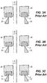
- FIG. 1 depicts one conventional gas regulator 10 comprising an actuator 12 and a balanced pressure regulator valve 14.
- the regulator valve 14 defines an inlet 16 for receiving gas from a gas distribution system, for example, and an outlet 18 for delivering gas to an end-user facility such as a factory, a restaurant, an apartment building, etc. having one or more appliances, for example.
- the regulator valve 14 includes a valve seat 22 disposed between the inlet 16 and the outlet 18. Gas must pass through the valve seat 22 to travel between the inlet 16 and the outlet 18 of the regulator valve 14.
- the actuator 12 is coupled to the regulator valve 14 to ensure that the pressure at the outlet 18 of the regulator valve 14, i.e., the outlet pressure, is in accordance with a desired outlet or control pressure.
- the actuator 12 is therefore in fluid communication with the regulator valve 14 via a valve mouth 34 and an actuator mouth 20.
- the actuator 12 includes a control assembly 22 for regulating the outlet pressure of the regulator valve 14 based on sensed outlet pressure.
- the control assembly 22 includes a diaphragm 24, a piston 32, and a control arm 26 having a valve plug 28 with a valve disc 31.
- the diaphragm 24 senses the outlet pressure of the regulator valve 14 and provides a response to move the valve plug 28 to open and close the regulator valve 14.
- the control assembly 22 further includes a control spring 30 in engagement with a top-side of the control assembly 22 to offset the outlet pressure sensed by the diaphragm 24. Accordingly, the desired outlet pressure, which may also be referred to as the control pressure, is set by the selection of the control spring 30.
- the diaphragm 24 is operably coupled to the control arm 26, and therefore, the valve plug 28, via the piston 32, and controls the opening of the regulator valve 14 based on the sensed outlet pressure. For example, when an end user operates an appliance, such as a furnace, for example, that places a demand on the gas distribution system downstream of the regulator 10, thereby decreasing the outlet pressure. Accordingly, the diaphragm 24 senses this decreased outlet pressure. This allows the control spring 30 to expand and move the piston 32 and the right-side of the control arm 26 downward, relative to the orientation of FIG. 1 . This displacement of the control arm 26 moves the valve plug 28 away from the valve seat 22 to open the regulator valve 14, thereby increasing the outlet flow to meet the increased demand from the appliance and increasing the outlet pressure back to the control pressure. So configured, the appliance may draw gas through the valve seat 22 and through the outlet 18 of the regulator valve 14.
- the balanced regulator valve 14 further includes a body 19 having a passage 21 that fluidly connects the fluid inlet 16 with the fluid outlet 18.
- the passage 21 includes a throat 23 in which the valve seat 22 is disposed.
- a load spring 25 is connected to a valve stem 27 that is operatively attached to the valve plug 28.
- the valve disc 131 of the valve plug 28 interacts with the valve seat 22 to control fluid flow through the valve body 19 from the inlet 16 to the outlet 18.
- the valve plug 28 includes a circumferential recess 29 into which the valve disc 31, which is typically rubber, is disposed. The valve disc 31 of the valve plug 28 contacts the valve seat 22 to achieve alignment and sealing engagement between the valve plug 28 and the valve seat 22.
- a diaphragm 33 is connected to the valve plug 28 and a plug housing or sleeve 35.
- the diaphragm 33 separates the passage 21 from a cavity 37 in the sleeve 35 that contains the load spring 25.
- the diaphragm 33 is responsive to pressure differences between the passage 21 and the cavity 37.
- a retainer 39 may be operatively attached to the valve stem 27 and retains the valve plug 28 on the valve stem 27.
- the retainer 39 may include one or more fasteners 39a, such as a nut, which are attached to the valve stem 27.
- One or more balancing passages or channels 41 fluidly connect the passage 21 with a chamber 43 located between the valve plug 28 and the cavity 37. Fluid forces on the valve plug 28 are balanced by fluid moving through the balancing channels 41.
- a contact seal between the valve disc 31 of the valve plug 28 and the valve seat 22 is affected by orientation and manufacturing tolerances between the disc 31 and valve seat 22.
- orientation and manufacturing tolerances often increase the amount of pressure required to make a seal, increasing lockup.
- the valve disc 31 of the valve plug 28 often approaches the valve seat 22 in a non-parallel manner.
- a seal between the disc 31 of the valve plug 28 and the valve seat 22 is made on only one side of the valve seat 22, e.g., the left side, as illustrated in FIG. 3B .
- US 2009/0261281 A1 discloses a gas regulator including an actuator, a valve, and a balanced port housing disposed within the valve for flow conditioning to convert turbulent flow within the valve to laminar flow when the fluid reaches the sensing point of a Pitot tube disposed within the outlet of the valve.
- CH 694279 A5 discloses an electromagnetic fluid control valve having a movable core of the electromagnet connected to a metal valve shaft.
- GB 157955 A discloses improvements in valves of the kind wherein the valve member is connected to the valve stem by means of a universal ball and socket joint and adapted to engage an inclined seating formed in the casing of the valve.
- WO 2012/012829 A2 discloses a valve member for a fluid flow control valve (such as a tap).
- a first exemplary aspect of the present invention relates to a balanced pressure regulator as defined in independent claim 1, and any of the dependent claims depending from claim 1.
- the balanced pressure regulator may include a valve body having a fluid inlet and a fluid outlet connected by a fluid passageway, a valve seat disposed within the fluid passageway, and a self-aligning valve plug at least partially disposed within the fluid passageway.
- the self-aligning valve plug includes a bore and interacts with the valve seat to selectively open or close the fluid passageway.
- a retainer is partially disposed within the bore of the self-aligning valve plug and operatively connects the self-aligning valve plug to a valve stem having a ball portion, the retainer having a recess for receiving the ball portion of the stem.
- the balanced pressure regulator further includes a balancing passage that fluidly connects the fluid passageway with the chamber.
- the self-aligning valve plug automatically rotates around the ball portion of the valve stem to achieve alignment and sealing engagement between a valve disc of the self-aligning valve plug and the valve seat.
- a balanced plug assembly for a balanced pressure regulator may include a sleeve, a self-aligning valve plug disposed within the sleeve, the self-aligning valve plug including a balancing channel and a bore, and a retainer partially disposed within the bore of the self-aligning valve plug.
- the retainer operatively connects the self-aligning valve plug to the valve stem and includes a recess adapted to receive a ball portion of the valve stem.
- the self-aligning valve plug and the retainer partially disposed therein automatically rotate about one or more of a longitudinal axis of the valve stem or an axis perpendicular to the longitudinal axis of the valve stem until alignment and sealing engagement between the valve disc and the valve seat occurs.
- a second aspect of the present invention relates to a method of automatically adjusting a valve plug for use with a balanced fluid regulating device as defined in independent claim 10, and any of the depending claims dependent on claim 10 , where the fluid regulating device includes an inlet, an outlet, a valve seat disposed between the inlet and the outlet, the valve plug adapted to be displaced relative to the valve seat, thereby controlling the flow of a fluid between the inlet and the outlet disposed within a regulator valve.
- the method comprising partially disposing a retainer within a bore of a valve plug, connecting the valve plug to a valve stem having a ball portion via the retainer, the retainer having a recess for receiving the ball portion of the valve stem, and automatically adjusting the valve plug around the flexible portion of the valve stem to achieve alignment and sealing engagement between a valve disc of the self-aligning valve plug and the valve seat.
- a balanced pressure regulator and/or a balanced plug assembly and/or method may further include any one or more of the following preferred forms.
- the retainer partially disposed within the self-aligning valve plug rotates around the ball portion of the valve stem to achieve alignment between the valve disc of the self-aligning valve plug and the valve seat.
- the self-aligning valve plug may include a circumferential recess adapted to receive the valve disc.
- the self-aligning valve plug may also rotate in one of a clockwise or counterclockwise direction relative to one or more of a longitudinal axis of the valve stem or an axis perpendicular to the longitudinal axis of the valve stem until alignment and sealing engagement between the valve disc of the self-aligning valve plug and the valve seat is achieved.
- the self-aligning valve plug may automatically move from a first position in which a longitudinal axis of the valve plug is not parallel to or disposed at an angle from the longitudinal axis of the valve seat to a second position in which the longitudinal axis of the valve plug is parallel to or aligned with the longitudinal axis of the valve seat.
- the retainer may include a base and a cylindrical body attached to the base via a fastener, and the cylindrical body may include a flange extending radially from an end of the cylindrical body disposed opposite the base.
- the cylindrical body may include a top surface and the flange includes an inner side wall, such that the top surface of the cylindrical body and the inner side wall form the recess adapted to receive the ball portion of the valve stem to operatively connect the valve stem with the self-aligning valve plug.
- a ball joint connection may also be formed between the ball portion of the valve stem and the recess, the recess forming a socket to receive the ball portion of the stem.
- the ball portion of the valve stem contacts at least one edge of the top surface of the cylindrical body of the retainer to form the ball joint connection, allowing a longitudinal axis of the self-aligning valve plug to align with a longitudinal axis of the valve seat.
- a gap is disposed between the flange of the cylindrical body of the retainer and the self-aligning valve plug, and a biasing member is disposed within the gap.
- automatically adjusting the valve plug may comprise rotating the retainer around the flexible portion of the valve stem to achieve alignment and sealing engagement between the valve disc of the valve plug and the valve seat, reducing a force required to achieve lockup.
- automatically adjusting the valve plug may comprise rotating the valve plug in one of a clockwise or counterclockwise direction relative to an axis perpendicular to the longitudinal axis of the valve stem and moving the valve plug in an axial direction along the length of the longitudinal axis of the valve stem until alignment and sealing engagement between the valve disc of the valve plug and the valve seat is achieved.
- automatically adjusting the valve plug may comprise automatically moving the valve plug, upon contact with a portion of the valve seat, from a first position in which a longitudinal axis of the valve plug is not parallel to or disposed at an angle from the longitudinal axis of the valve seat to a second position in which the longitudinal axis of the valve plug is parallel to or aligned with the longitudinal axis of the valve seat.
- partially disposing a retainer within the bore of the valve plug may comprise partially disposing a cylindrical body having a flange radially extending therefrom within an end of the bore of the valve plug and disposing a retainer base within another end of the bore opposite the end in which the cylindrical body is partially disposed.
- partially disposing the retainer within the bore of the valve plug may further comprise attaching the retainer base to the cylindrical body via a fastener.
- the flexible portion of the valve stem may comprise a ball portion
- the method may further comprise forming a ball joint connection between the ball portion of the valve stem and a recess of the retainer, the recess forming a socket to receive the ball portion of the stem.
- the method may comprise simultaneously rotating the valve plug and the retainer around the ball portion of the valve stem or a longitudinal axis of the valve stem upon contact with a portion of the valve seat.
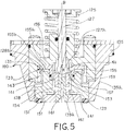
- a balanced pressure regulator is generally referred to by reference numeral 114 in FIG. 4 .
- the balanced pressure regulator of FIGS. 4 and 5 includes elements that correspond to the elements of the balanced pressure regulator of FIGS. 1-2 , those elements will be numbered similarly, the only difference being that the reference numerals of FIGS. 4-5 are increased by a multiple of 100.
- corresponding elements of FIGS. 4 and 5 will be numbered exactly 100 greater than the corresponding elements illustrated in FIGS. 1-2 .
- the balanced pressure regulator valve 114 includes a fluid inlet 116 and a fluid outlet 118 and a body 119 having a passage 121 that fluidly connects the fluid inlet 116 with the fluid outlet 118.
- the passage 121 includes a throat 123 in which a valve seat 122 is disposed.
- a load spring 125 is connected to a valve stem 127 that is operatively attached to a self-aligning valve plug 128.
- the self-aligning valve plug 128 interacts with the valve seat 122 to control fluid flow between the inlet 116 and the outlet 118. More specifically, the self-aligning valve plug 128 includes a circumferential recess 129 into which a rubber disc 131 is disposed. The disc 131 of the self-aligning valve plug 128 contacts the valve seat 122 to achieve alignment and sealing engagement between the self-aligning valve plug 128 and the valve seat 122, as explained in more detail below.
- a balanced plug assembly 160 includes a sleeve 135, the self-aligning valve plug 128, and a retainer 139.
- the sleeve 135 has a hollow bore that helps retain and guide the self-aligning valve plug 128 as the self-aligning valve plug 128 reciprocates within the valve body 119 to control fluid flow.
- the sleeve 135 may have an angled surface outer surface 135a to enhance clearance within the valve body 119 and/or enhance assembly of the pressure regulator 114.
- a diaphragm 133 is connected to the self-aligning valve plug 128 and the sleeve 135.
- the diaphragm 133 separates the passage 121 from a cavity 137 in the housing 119 that contains the load spring 125.
- the diaphragm 133 is responsive to pressure differences between the passage 121 and the cavity 137.
- a retainer 139 is operatively attached to the valve stem 127 and retains the self-aligning valve plug 128 within the sleeve 135.
- the retainer 139 includes a fastener 139a, such as a threaded bolt in this example, which is operatively attached to a portion of the valve stem 127, as will be described in more detail below.
- One or more balancing passages or channels 141 fluidly connect passage 121 with a chamber 143 located between the self-aligning valve plug 128 and the cavity 137. Fluid forces on the self-aligning valve plug 128 are balanced by fluid moving through the balancing channels 141 and up to the chamber 43, for example.
- a longitudinal axis D of the self-aligning valve plug 128 is disposed parallel to a longitudinal axis C of the valve seat 122, and complete sealing engagement between the valve disc 131 of the self-aligning valve plug 128 and the valve seat to occur.
- the self-aligning valve plug 128 of the balanced plug assembly 160 is designed such that it is self-aligning or capable of automatically adjusting or moving to achieve alignment and sealing engagement between the valve disc 131 of the self-aligning valve plug 128 and the valve seat 122.
- the self-aligning valve plug 128 reduces indentations to the valve disc 131 during operation of the regulator valve 114, for example. As a result, the force required to achieve the desired outlet pressure (lockup) during extended use of the regulator 100, for example, is maintained constant and regulator performance is improved.
- the self-aligning valve plug 128 is so configured such that it is operatively connected to the valve stem 127 via the retainer 139 such that a ball portion 127a of the valve stem 127 is disposed within a recess of the retainer 139, essentially forming a ball joint between the valve stem 127 and the retainer 139.
- the self-aligning valve plug 128 and the retainer 139 partially disposed therein are able to rotate around the ball portion 127a of the valve stem 127 during operation of the valve to achieve proper alignment and sealing engagement between the valve disc 131 of the self-aligning valve plug 128 and the valve seat 122.
- valve disc 131 of the self-aligning valve plug 128 contacts a portion of the valve seat 122
- the self-aligning valve plug 128 and the retainer 139 rotate around the ball portion 127a of the valve stem 127 to achieve a position parallel to the longitudinal axis C of the valve seat 122 ( FIG. 4 ) and alignment and sealing engagement with the valve seat 122 occur.
- the retainer 139 includes a cylindrical portion 153 having a flange 155 extending radially therefrom, such that the cylindrical portion 153 and the flange 155 may form a retaining nut in one example.
- the cylindrical portion 153 of the retainer 139 is disposed within a bore 154 of the self-aligning valve plug 128.
- the flange 155 includes a top shoulder surface 155a that abuts a diaphragm housing 156.
- the flange 155 also includes a bottom shoulder surface 155b that abuts a portion the diaphragm 133 disposed between a top shoulder surface 128a of the self-aligning valve plug 128 and the bottom shoulder surface 155b of the flange.
- a retainer base 151 is disposed within an end of the bore located opposite to the end in which the cylindrical portion 153 is disposed.
- the retainer base 151 helps retain the self-aligning valve plug 128 within the throat 123 and prevents unwanted axial displacement of the self-aligning valve plug 128 outside of the sleeve 135, for example.
- a fastener 139a having a center hole for receiving inlet pressure during operation of the valve 114 connects the retainer base 151 to the cylindrical body 153 of the retainer 139.
- the cylindrical body 153 includes a top surface 157, and the flange 155 includes an inner side wall 159, such that a recess 161 is formed between the top surface 157 of the cylindrical body 153 and the inner side wall 159 of the flange 155.
- the stem 127 includes the ball portion 127a that fits within the recess 161 formed between the top surface 157 of the cylindrical body 153 and the inner side wall 159 of the flange 155.
- the ball joint connection is formed between the ball portion 127a of the stem 127 and the recess 161, which essentially forms a socket to receive the ball portion 127a.
- the ball portion 127a contacts at least one edge of the top surface 157 of the cylindrical body 155 and is operatively secured to the retainer 139, allowing the self-aligning valve plug 128 and retainer 139 to rotate around the ball portion 127a or a longitudinal axis B of the stem 127 upon contacting a portion of the valve seat 122.
- the self-aligning valve plug 128 and the retainer 139 partially disposed therein will rotate until they reach a position parallel to a longitudinal axis C of the valve seat 122, allowing alignment and sealing engagement to be achieved with reduced indentation to the valve disc 131.
- the ball portion 127a of the stem 127 allows the retainer 139 and the self-aligning valve plug 128 to automatically self-align or self-adjust or move and/or rotate or pivot when the valve disc 131 contacts a portion of the valve seat 122 until alignment and sealing engagement between the entire valve disc 131 and the valve seat 122 is achieved.
- Such movement of the self-aligning valve plug 128 thus reduces the force required to achieve lockup and results in a more efficient performance of the regulator 114.
- valve disc 131 often only contacts a portion of the valve seat 122.
- the longitudinal axis D of the self-aligning valve plug 128 may not be parallel to the longitudinal axis C of the valve seat 122, resulting in only a portion of the valve seat 122 initially contacting the valve disc 131.
- the initial force provided by the valve disc 131 of the self-aligning valve plug 128 to only a portion of the valve seat 122 causes the self-aligning valve plug 128 and retainer 139 connected thereto to adjust or rotate about one or more of the longitudinal axis B of the valve stem 127 and/or an axis R perpendicular to the longitudinal axis B of the valve stem 127.
- the axis R can be referred to as the yaw axis of the valve stem 127. While in FIG. 5 , the yaw axis R extends directly into the page, the yaw axis is actually defined as any axis that extends perpendicular to the longitudinal axis B of the valve stem 127.
- Such rotation of the self-aligning valve plug 128 and retainer 139 occurs until alignment and sealing engagement between the valve disc 131 of the self-aligning valve plug 128 and the valve seat 122 is achieved.
- valve disc 131 contacts only a portion of the valve seat 122, e.g., a right-side portion
- the self-aligning valve plug 128 and the retainer 139 rotate about the yaw axis R in a clockwise direction such that a left-side of the valve disc 131 of the self-aligning valve plug 128 moves toward the left-side of the valve seat 122 until complete alignment and sealing engagement with the valve seat 122 occurs.
- valve disc 131 contacts only another portion of the valve seat 122, e.g., a left-side portion
- the self-aligning valve plug 128 and the retainer 139 rotate about the yaw axis in a counter-clockwise direction such that the right-side of the valve disc 131 of the self-aligning valve plug 127 moves toward the right-side of the valve seat 122 until complete alignment and sealing engagement with the valve seat 122 occurs.
- the longitudinal axis D of the self-aligning valve plug 128 moves from a first position that is not parallel to or disposed at an angle ⁇ from the longitudinal axis C of the valve seat 122 to a second position that is parallel to or aligned with the longitudinal axis C of the valve seat 122 after the valve disc 131 contacts only a portion of the valve seat 122.
- Such automatic movement or rotation reduces the amount of indentation to the valve disc 131 and the force required to achieve lockup.
- FIG. 6 also illustrates a gap 162 formed between the flange 155 of the cylindrical body 153 and the self-aligning valve plug 128, for example.
- a biasing member 164 may be disposed within the gap to assist with the rotational movement of the self-aligning valve plug 128 and the retainer 139 about the ball portion 127a of the valve stem 127. While the biasing member 164 of FIG.
- o-ring 6 may comprise one or more o-rings
- biasing members other than an o-ring or pair of o-rings, such as a wave spring, a compression coil spring, or any other biasing mechanism, for example, may alternatively be used to achieve the same function of the o-ring(s) and the biasing member 164 in general.
- valve stem 127 may alternatively include flexible portion that similarly allows the valve plug and retainer to simultaneously rotate around the flexible portion (or the longitudinal axis of the valve stem) upon contact with a portion of the valve seat.
- the present invention provides an advantageous means for enabling the balanced self-aligning valve plug 128 to self-adjust while approaching and/or upon initial contact with a portion of the valve seat 122 of the regulator valve 114.
- the regulator valve 114 described herein is merely one example of a fluid control device incorporating the principles of the present disclosure.
- Other fluid control devices including other regulators and control valves may also benefit from the structures and/or advantages of the present disclosure. More generally, although certain example apparatus and methods have been described herein, the scope of coverage of this patent is not limited thereto. On the contrary, this patent covers all methods, apparatus and articles of manufacture fairly falling within the scope of the appended claims.
Landscapes
- Engineering & Computer Science (AREA)
- General Engineering & Computer Science (AREA)
- Physics & Mathematics (AREA)
- Mechanical Engineering (AREA)
- Fluid Mechanics (AREA)
- General Physics & Mathematics (AREA)
- Automation & Control Theory (AREA)
- Control Of Fluid Pressure (AREA)
- Taps Or Cocks (AREA)
- Lift Valve (AREA)
- Valves And Accessory Devices For Braking Systems (AREA)
Claims (15)
- Reguliereinrichtung mit Druckausgleich (114), umfassend:einen Ventilkörper (119) mit einem Fluideinlass (116) und einem Fluidauslass (118), die durch einen Fluidkanal (121) verbunden sind;einen Ventilsitz (122), der in dem Fluidkanal angeordnet ist;einen selbstausrichtenden Ventilstopfen (128), der zumindest zum Teil in dem Fluidkanal angeordnet ist, wobei der selbstausrichtende Ventilstopfen ein Rundloch (154) aufweist und mit dem Ventilsitz zusammenwirkt, um den Fluidkanal wahlweise zu öffnen oder zu schließen;ein Rückhalteelement (139), das zum Teil in dem Rundloch des selbstausrichtenden Ventilstopfens angeordnet ist und den selbstausrichtenden Ventilstopfen funktional mit einem Ventilschaft (127) verbindet, der einen Kugelabschnitt (127a) aufweist, wobei das Rückhalteelement eine Ausnehmung (161) zum Aufnehmen des Kugelabschnitts des Ventilschafts aufweist, wobei das Rückhalteelement eine Basis (151) und einen zylindrischen Körper (153) umfasst, der mittels eines Befestigungselements (139a) an der Basis befestigt ist, und wobei der zylindrische Körper einen Flansch (155) aufweist, der sich von einem entgegengesetzt zu der Basis angeordneten Ende des zylindrischen Körpers in radialer Richtung erstreckt, wobei der zylindrische Körper ferner eine Oberseite (157) aufweist, wobei der Kugelabschnitt des Ventilschafts zumindest eine Kante der Oberseite des zylindrischen Körpers berührt, undeinen Ausgleichskanal (141), der den Fluidkanal fluiddurchlässig mit einer Kammer (143) verbindet;wobei sich der selbstausrichtende Ventilstopfen automatisch um den Kugelabschnitt des Ventilschafts dreht, um eine Ausrichtung und abdichtende Anlage zwischen einer Ventilscheibe (131) des selbstausrichtenden Ventilstopfens und dem Ventilsitz zu erreichen.
- Reguliereinrichtung mit Druckausgleich nach Anspruch 1, wobei sich das zum Teil innerhalb des selbstausrichtenden Ventilstopfens angeordnete Rückhalteelement um den Kugelabschnitt des Ventilschafts dreht, um eine Ausrichtung und abdichtende Anlage zwischen der Ventilscheibe des selbstausrichtenden Ventilstopfens und dem Ventilsitz zu erreichen, wodurch eine zum Erreichen eines Verschlusses erforderliche Kraft reduziert wird.
- Reguliereinrichtung mit Druckausgleich nach einem der vorhergehenden Ansprüche, wobei der selbstausrichtende Ventilstopfen eine umfängliche Ausnehmung (129) aufweist, die zur Aufnahme der Ventilscheibe ausgebildet ist.
- Reguliereinrichtung mit Druckausgleich nach einem der vorhergehenden Ansprüche, wobei sich der selbstausrichtende Ventilstopfen entweder im Uhrzeigersinn oder entgegen dem Uhrzeigersinn in Bezug auf entweder eine Achse (R) senkrecht zur Längsachse (B) des Ventilschafts (127) oder eine Längsachse (B) des Ventilschafts dreht und sich in einer axialen Richtung entlang der Länge der Längsachse des Ventilschafts bewegt, bis eine Ausrichtung und abdichtende Anlage zwischen der Ventilscheibe und dem Ventilsitz erreicht ist.
- Reguliereinrichtung mit Druckausgleich nach einem der vorhergehenden Ansprüche, wobei sich der selbstausrichtende Ventilstopfen bei Kontakt mit einem Teil des Ventilsitzes automatisch aus einer ersten Stellung, in der eine Längsachse des selbstausrichtenden Ventilstopfens nicht parallel zu der Längsachse des Ventilsitzes oder in einem Winkel zu dieser liegt, in eine zweite Stellung bewegt, in der die Längsachse des selbstausrichtenden Ventilstopfens parallel zu der Längsachse des Ventilsitzes oder ausgerichtet zu dieser ist.
- Reguliereinrichtung mit Druckausgleich nach einem der vorhergehenden Ansprüche, wobei der zylindrische Körper die Oberseite aufweist und der Flansch eine innere Seitenwand (159) aufweist, wobei die Oberseite des zylindrischen Körpers und die innere Seitenwand die Ausnehmung bilden, die zur Aufnahme des Kugelabschnitts des Ventilschafts ausgebildet ist, um den Ventilschaft funktional mit dem selbstausrichtenden Ventilstopfen zu verbinden.
- Reguliereinrichtung mit Druckausgleich nach einem der vorhergehenden Ansprüche, wobei zwischen dem Kugelabschnitt des Ventilschafts und der Ausnehmung eine Kugelgelenkverbindung ausgebildet ist, wobei die Ausnehmung eine Gelenkpfanne zum Aufnehmen des Kugelabschnitts des Ventilschafts bildet.
- Reguliereinrichtung mit Druckausgleich nach einem der vorhergehenden Ansprüche, wobei der Kugelabschnitt des Ventilschafts die mindestens eine Kante der Oberseite des zylindrischen Körpers des Rückhalteelements berührt, um die Kugelgelenkverbindung zu bilden, so dass sich eine Längsachse des selbstausrichtenden Ventilstopfens zu einer Längsachse des Ventilsitzes ausrichten kann.
- Reguliereinrichtung mit Druckausgleich nach einem der vorhergehenden Ansprüche, ferner umfassend:eine Muffe (135), in welcher der selbstausrichtende Ventilstopfen angeordnet ist, und/oderein Vorspannelement (164), das in einem Spalt (162) angeordnet ist, der zwischen dem Flansch des Rückhalteelements und dem selbstausrichtenden Ventilstopfen ausgebildet ist.
- Verfahren zum automatischen Justieren eines Ventilstopfens (128) zur Verwendung mit einer Fluidreguliereinrichtung (114) mit Druckausgleich, wobei die Fluidreguliereinrichtung mit Druckausgleich einen Einlass (116) und einen Auslass (118) ausweist, wobei der Einlass und der Auslass durch einen Fluidkanal (121) verbunden sind, einen Ventilsitz (122), der zwischen dem Einlass und dem Auslass angeordnet ist, wobei der Ventilstopfen dafür ausgebildet ist, relativ zu dem Ventilsitz verschoben zu werden, wodurch die Strömung eines Fluids zwischen dem Einlass und dem Auslass gesteuert wird, angeordnet in einem Regelventil, wobei das Verfahren umfasst:Anordnen eines Rückhalteelements (139) zum Teil in einem Rundloch (154) eines Ventilstopfens,Verbinden des Ventilstopfens mit einem Ventilschaft (127), der einen Kugelabschnitt (127a) aufweist, über das Rückhalteelement, wobei das Rückhalteelement eine Ausnehmung (161) zum Aufnehmen des Kugelabschnitts des Ventilschafts aufweist,Befestigen eines zylindrischen Körpers (153) des Rückhalteelements an einer Basis (151) des Rückhalteelements mittels eines Befestigungselements (139a), wobei der zylindrische Körper einen Flansch (155) aufweist, der sich von einem entgegengesetzt zur Basis angeordneten Ende des zylindrischen Körpers in radialer Richtung erstreckt, wobei der zylindrische Körper ferner eine Oberseite (157) aufweist,in Berührung bringen des Kugelabschnitts des Ventilschafts mit zumindest einer Kante der Oberseite des zylindrischen Körpers,fluiddurchlässiges Verbinden des Fluidkanals (121) mit einer Kammer (143) über einen Ausgleichskanal (141), undautomatisches Justieren des Ventilstopfens um den Kugelabschnitt des Ventilschafts herum, um eine Ausrichtung und abdichtende Anlage zwischen einer Ventilscheibe (131) des selbstausrichtenden Ventilstopfens und dem Ventilsitz zu erreichen.
- Verfahren nach Anspruch 10, wobei das automatische Justieren des Ventilstopfens das Drehen des Rückhalteelements um den Kugelabschnitt des Ventilschafts herum umfasst, um eine Ausrichtung und abdichtende Anlage zwischen der Ventilscheibe des Ventilstopfens und dem Ventilsitz zu erreichen, wodurch eine zum Erreichen eines Verschlusses erforderliche Kraft reduziert wird.
- Verfahren nach einem der Ansprüche 10 oder 11, wobei das automatische Justieren des Ventilstopfens das Drehen des Ventilstopfens entweder im Uhrzeigersinn oder entgegen dem Uhrzeigersinn in Bezug auf entweder eine Achse (R) senkrecht zur Längsachse (B) des Ventilschafts oder die Längsachse (B) des Ventilschafts umfasst, sowie das Bewegen des Ventilstopfens in einer axialen Richtung entlang der Länge der Längsachse des Ventilschafts, bis eine Ausrichtung und abdichtende Anlage zwischen der Ventilscheibe des Ventilstopfens und dem Ventilsitz erreicht ist.
- Verfahren nach einem der Ansprüche 10 bis 12, wobei das automatische Justieren des Ventilstopfens das automatische Bewegen des Ventilstopfens bei Kontakt mit einem Teil des Ventilsitzes umfasst, und zwar aus einer ersten Stellung, in der eine Längsachse des Ventilstopfens nicht parallel zu der Längsachse des Ventilsitzes oder in einem Winkel zu dieser liegt, in eine zweite Stellung, in der die Längsachse des Ventilstopfens parallel zu der Längsachse des Ventilsitzes oder ausgerichtet mit dieser ist.
- Verfahren nach einem der Ansprüche 10 bis 13, wobei das Anordnen des Rückhalteelements (139) zum Teil in dem Rundloch des Ventilstopfens das Anordnen des zylindrischen Körpers mit dem sich von diesem aus in radialer Richtung erstreckenden Flansch (155) zum Teil in einem Ende des Rundlochs des Ventilstopfens und das Anordnen der Basis des Rückhalteelements in einem anderen Ende des Rundlochs entgegengesetzt zu dem Ende, in dem der zylindrische Körper zum Teil angeordnet ist, umfasst, wobei das Anordnen der Rückhalteelements zum Teil in dem Rundloch des Ventilstopfens ferner das Befestigen der Basis des Rückhalteelements an dem zylindrischen Körper mittels des Befestigungselements (139a) umfasst.
- Verfahren nach einem der Ansprüche 10 bis 14, ferner umfassend das Bilden einer Kugelgelenkverbindung zwischen dem Kugelabschnitt (127a) des Ventilschafts und der Ausnehmung (161) des Rückhalteelements, wobei die Ausnehmung eine Gelenkpfanne zum Aufnehmen des Kugelabschnitts des Ventilschafts bildet.
Applications Claiming Priority (2)
| Application Number | Priority Date | Filing Date | Title |
|---|---|---|---|
| CN201210388194.8A CN103711964B (zh) | 2012-09-28 | 2012-09-28 | 自对准阀塞 |
| PCT/US2013/062097 WO2014052706A1 (en) | 2012-09-28 | 2013-09-27 | Self-aligning valve plug |
Publications (2)
| Publication Number | Publication Date |
|---|---|
| EP2901060A1 EP2901060A1 (de) | 2015-08-05 |
| EP2901060B1 true EP2901060B1 (de) | 2018-05-02 |
Family
ID=49322754
Family Applications (1)
| Application Number | Title | Priority Date | Filing Date |
|---|---|---|---|
| EP13774336.5A Active EP2901060B1 (de) | 2012-09-28 | 2013-09-27 | Selbstausrichtender ventilstecker |
Country Status (9)
| Country | Link |
|---|---|
| EP (1) | EP2901060B1 (de) |
| JP (1) | JP6595338B2 (de) |
| CN (1) | CN103711964B (de) |
| AR (1) | AR092722A1 (de) |
| BR (1) | BR112015006789A2 (de) |
| CA (1) | CA2885747C (de) |
| MX (1) | MX359558B (de) |
| RU (1) | RU2647949C2 (de) |
| WO (1) | WO2014052706A1 (de) |
Families Citing this family (5)
| Publication number | Priority date | Publication date | Assignee | Title |
|---|---|---|---|---|
| ITUB20150884A1 (it) * | 2015-05-25 | 2016-11-25 | Arno Drechsel | Dispositivo regolatore di pressione per un liquido |
| JP2019520526A (ja) | 2016-05-25 | 2019-07-18 | スウェージロック カンパニー | 自己整列式のステム先端を備えたバルブ |
| CN106090359B (zh) * | 2016-06-30 | 2018-05-22 | 重庆市山城燃气设备有限公司 | 一种天然气管道用压力调节组件 |
| CN111102365A (zh) * | 2018-10-29 | 2020-05-05 | 艾默生过程管理调节技术公司 | 流体调节器 |
| CN111442096B (zh) * | 2020-03-18 | 2022-07-19 | 合肥通用机械研究院有限公司 | 一种阀芯自旋式被动防控型含固多相流控制阀 |
Family Cites Families (17)
| Publication number | Priority date | Publication date | Assignee | Title |
|---|---|---|---|---|
| GB157955A (en) * | 1918-05-24 | 1922-02-16 | Leon Bloch | Valve |
| DE847015C (de) * | 1943-01-30 | 1952-08-18 | Gustav Friedrich Gerdts | Bodenverschluss fuer Kesselwagen |
| JPS52117628U (de) * | 1976-03-03 | 1977-09-06 | ||
| SE7909631L (sv) * | 1978-12-11 | 1980-06-12 | Applied Power Inc | Manoverventil, som regleras elektromagnetiskt |
| DE3723959C2 (de) * | 1987-07-20 | 1996-09-19 | Bosch Siemens Hausgeraete | Magnetventil |
| DE4424724C2 (de) * | 1994-07-13 | 1996-07-04 | Siemens Ag | Steuerventil |
| JP3020569U (ja) * | 1995-03-30 | 1996-02-02 | 味の素株式会社 | バルブの弁体部構造 |
| CH694279A5 (fr) * | 2001-03-13 | 2004-10-29 | Parker Lucifer Sa | Valve à commande électromagnétique pour fluide. |
| US6851658B2 (en) * | 2003-02-04 | 2005-02-08 | Fisher Controls International Inc. | Control valve trim and bore seal |
| JP2005069366A (ja) * | 2003-08-25 | 2005-03-17 | Miura Co Ltd | バルブ |
| JP2007303542A (ja) * | 2006-05-11 | 2007-11-22 | Keihin Corp | 電磁流体制御弁 |
| US8281803B2 (en) * | 2008-04-18 | 2012-10-09 | Fisher Controls International Llc | Balanced port housing with integrated flow conditioning |
| US8240327B2 (en) * | 2008-04-21 | 2012-08-14 | Emerson Process Management Regulator Technologies, Inc. | Pressure loaded service regulator with pressure balanced trim |
| US9639093B2 (en) * | 2009-05-07 | 2017-05-02 | Parker-Hannifin Corporation | Self-aligning axially constrained regulator valve assembly |
| CA2787051C (en) * | 2010-01-18 | 2016-09-20 | Gregory Lawrence Foust | Fluid regulator having pressure registration flow modifier |
| AU2011284786A1 (en) * | 2010-07-29 | 2013-03-07 | Pride Technologies International Pty Ltd | A jumper valve |
| CN203189820U (zh) * | 2012-09-28 | 2013-09-11 | 艾默生过程管理调节技术公司 | 平衡压强调节器以及平衡阀塞组件 |
-
2012
- 2012-09-28 CN CN201210388194.8A patent/CN103711964B/zh active Active
-
2013
- 2013-09-27 EP EP13774336.5A patent/EP2901060B1/de active Active
- 2013-09-27 BR BR112015006789A patent/BR112015006789A2/pt active Search and Examination
- 2013-09-27 JP JP2015534693A patent/JP6595338B2/ja active Active
- 2013-09-27 AR ARP130103495A patent/AR092722A1/es unknown
- 2013-09-27 CA CA2885747A patent/CA2885747C/en active Active
- 2013-09-27 WO PCT/US2013/062097 patent/WO2014052706A1/en active Application Filing
- 2013-09-27 MX MX2015003919A patent/MX359558B/es active IP Right Grant
- 2013-09-27 RU RU2015112676A patent/RU2647949C2/ru active
Non-Patent Citations (1)
| Title |
|---|
| None * |
Also Published As
| Publication number | Publication date |
|---|---|
| MX2015003919A (es) | 2016-01-08 |
| JP6595338B2 (ja) | 2019-10-23 |
| MX359558B (es) | 2018-10-01 |
| EP2901060A1 (de) | 2015-08-05 |
| CA2885747A1 (en) | 2014-04-03 |
| AR092722A1 (es) | 2015-04-29 |
| CN103711964B (zh) | 2018-06-19 |
| RU2647949C2 (ru) | 2018-03-21 |
| CN103711964A (zh) | 2014-04-09 |
| RU2015112676A (ru) | 2016-11-20 |
| CA2885747C (en) | 2020-09-08 |
| WO2014052706A1 (en) | 2014-04-03 |
| BR112015006789A2 (pt) | 2017-07-04 |
| JP2015532480A (ja) | 2015-11-09 |
Similar Documents
| Publication | Publication Date | Title |
|---|---|---|
| US9200716B2 (en) | Self aligning valve plug | |
| EP3123263B1 (de) | Doppelausgangdruckregler mit beweglichem sitz | |
| EP2901060B1 (de) | Selbstausrichtender ventilstecker | |
| US8459297B2 (en) | Balanced valve cartridge | |
| EP2898386B1 (de) | Ausgeglichener regler mit einer einlassdruckmesssonde | |
| US8500092B2 (en) | Secondary seat for gas regulator | |
| WO2017024795A1 (zh) | 一种电子膨胀阀 | |
| US20110174394A1 (en) | Balanced fluid valve | |
| EP3365742B1 (de) | Druckregelvorrichtung mit variablem hubanschlag | |
| EP2898240B1 (de) | Selbstausrichtender ventilanschluss | |
| EP3250975B1 (de) | Mechanismus und verfahren zur anpassung der grösse eines ausgeglichenen ventils | |
| EP3108320B1 (de) | Ausgeglichener regler mit ausgeglichener trimmung mit variablem druckempfindlichem bereich | |
| CN203189820U (zh) | 平衡压强调节器以及平衡阀塞组件 | |
| CN202371234U (zh) | 轴向流动控制阀 | |
| JP2510852Y2 (ja) | 減圧弁 | |
| JP2014109982A (ja) | 制御バルブ | |
| JPH0635548A (ja) | 圧力制御弁装置 | |
| WO2012126182A1 (en) | Balanced axial flow pressure regulator |
Legal Events
| Date | Code | Title | Description |
|---|---|---|---|
| PUAI | Public reference made under article 153(3) epc to a published international application that has entered the european phase |
Free format text: ORIGINAL CODE: 0009012 |
|
| 17P | Request for examination filed |
Effective date: 20150428 |
|
| AK | Designated contracting states |
Kind code of ref document: A1 Designated state(s): AL AT BE BG CH CY CZ DE DK EE ES FI FR GB GR HR HU IE IS IT LI LT LU LV MC MK MT NL NO PL PT RO RS SE SI SK SM TR |
|
| AX | Request for extension of the european patent |
Extension state: BA ME |
|
| DAX | Request for extension of the european patent (deleted) | ||
| STAA | Information on the status of an ep patent application or granted ep patent |
Free format text: STATUS: EXAMINATION IS IN PROGRESS |
|
| 17Q | First examination report despatched |
Effective date: 20170606 |
|
| GRAP | Despatch of communication of intention to grant a patent |
Free format text: ORIGINAL CODE: EPIDOSNIGR1 |
|
| STAA | Information on the status of an ep patent application or granted ep patent |
Free format text: STATUS: GRANT OF PATENT IS INTENDED |
|
| RIC1 | Information provided on ipc code assigned before grant |
Ipc: F16K 31/165 20060101AFI20171024BHEP Ipc: G05D 16/06 20060101ALI20171024BHEP Ipc: F16K 1/36 20060101ALI20171024BHEP |
|
| INTG | Intention to grant announced |
Effective date: 20171115 |
|
| GRAS | Grant fee paid |
Free format text: ORIGINAL CODE: EPIDOSNIGR3 |
|
| GRAA | (expected) grant |
Free format text: ORIGINAL CODE: 0009210 |
|
| STAA | Information on the status of an ep patent application or granted ep patent |
Free format text: STATUS: THE PATENT HAS BEEN GRANTED |
|
| AK | Designated contracting states |
Kind code of ref document: B1 Designated state(s): AL AT BE BG CH CY CZ DE DK EE ES FI FR GB GR HR HU IE IS IT LI LT LU LV MC MK MT NL NO PL PT RO RS SE SI SK SM TR |
|
| REG | Reference to a national code |
Ref country code: GB Ref legal event code: FG4D |
|
| REG | Reference to a national code |
Ref country code: CH Ref legal event code: EP Ref country code: AT Ref legal event code: REF Ref document number: 995628 Country of ref document: AT Kind code of ref document: T Effective date: 20180515 |
|
| REG | Reference to a national code |
Ref country code: DE Ref legal event code: R096 Ref document number: 602013036946 Country of ref document: DE Ref country code: IE Ref legal event code: FG4D |
|
| REG | Reference to a national code |
Ref country code: NL Ref legal event code: MP Effective date: 20180502 |
|
| REG | Reference to a national code |
Ref country code: LT Ref legal event code: MG4D |
|
| PG25 | Lapsed in a contracting state [announced via postgrant information from national office to epo] |
Ref country code: BG Free format text: LAPSE BECAUSE OF FAILURE TO SUBMIT A TRANSLATION OF THE DESCRIPTION OR TO PAY THE FEE WITHIN THE PRESCRIBED TIME-LIMIT Effective date: 20180802 Ref country code: FI Free format text: LAPSE BECAUSE OF FAILURE TO SUBMIT A TRANSLATION OF THE DESCRIPTION OR TO PAY THE FEE WITHIN THE PRESCRIBED TIME-LIMIT Effective date: 20180502 Ref country code: NO Free format text: LAPSE BECAUSE OF FAILURE TO SUBMIT A TRANSLATION OF THE DESCRIPTION OR TO PAY THE FEE WITHIN THE PRESCRIBED TIME-LIMIT Effective date: 20180802 Ref country code: SE Free format text: LAPSE BECAUSE OF FAILURE TO SUBMIT A TRANSLATION OF THE DESCRIPTION OR TO PAY THE FEE WITHIN THE PRESCRIBED TIME-LIMIT Effective date: 20180502 Ref country code: LT Free format text: LAPSE BECAUSE OF FAILURE TO SUBMIT A TRANSLATION OF THE DESCRIPTION OR TO PAY THE FEE WITHIN THE PRESCRIBED TIME-LIMIT Effective date: 20180502 Ref country code: ES Free format text: LAPSE BECAUSE OF FAILURE TO SUBMIT A TRANSLATION OF THE DESCRIPTION OR TO PAY THE FEE WITHIN THE PRESCRIBED TIME-LIMIT Effective date: 20180502 |
|
| PG25 | Lapsed in a contracting state [announced via postgrant information from national office to epo] |
Ref country code: HR Free format text: LAPSE BECAUSE OF FAILURE TO SUBMIT A TRANSLATION OF THE DESCRIPTION OR TO PAY THE FEE WITHIN THE PRESCRIBED TIME-LIMIT Effective date: 20180502 Ref country code: RS Free format text: LAPSE BECAUSE OF FAILURE TO SUBMIT A TRANSLATION OF THE DESCRIPTION OR TO PAY THE FEE WITHIN THE PRESCRIBED TIME-LIMIT Effective date: 20180502 Ref country code: NL Free format text: LAPSE BECAUSE OF FAILURE TO SUBMIT A TRANSLATION OF THE DESCRIPTION OR TO PAY THE FEE WITHIN THE PRESCRIBED TIME-LIMIT Effective date: 20180502 Ref country code: LV Free format text: LAPSE BECAUSE OF FAILURE TO SUBMIT A TRANSLATION OF THE DESCRIPTION OR TO PAY THE FEE WITHIN THE PRESCRIBED TIME-LIMIT Effective date: 20180502 Ref country code: GR Free format text: LAPSE BECAUSE OF FAILURE TO SUBMIT A TRANSLATION OF THE DESCRIPTION OR TO PAY THE FEE WITHIN THE PRESCRIBED TIME-LIMIT Effective date: 20180803 |
|
| REG | Reference to a national code |
Ref country code: AT Ref legal event code: MK05 Ref document number: 995628 Country of ref document: AT Kind code of ref document: T Effective date: 20180502 |
|
| PG25 | Lapsed in a contracting state [announced via postgrant information from national office to epo] |
Ref country code: SK Free format text: LAPSE BECAUSE OF FAILURE TO SUBMIT A TRANSLATION OF THE DESCRIPTION OR TO PAY THE FEE WITHIN THE PRESCRIBED TIME-LIMIT Effective date: 20180502 Ref country code: RO Free format text: LAPSE BECAUSE OF FAILURE TO SUBMIT A TRANSLATION OF THE DESCRIPTION OR TO PAY THE FEE WITHIN THE PRESCRIBED TIME-LIMIT Effective date: 20180502 Ref country code: CZ Free format text: LAPSE BECAUSE OF FAILURE TO SUBMIT A TRANSLATION OF THE DESCRIPTION OR TO PAY THE FEE WITHIN THE PRESCRIBED TIME-LIMIT Effective date: 20180502 Ref country code: DK Free format text: LAPSE BECAUSE OF FAILURE TO SUBMIT A TRANSLATION OF THE DESCRIPTION OR TO PAY THE FEE WITHIN THE PRESCRIBED TIME-LIMIT Effective date: 20180502 Ref country code: AT Free format text: LAPSE BECAUSE OF FAILURE TO SUBMIT A TRANSLATION OF THE DESCRIPTION OR TO PAY THE FEE WITHIN THE PRESCRIBED TIME-LIMIT Effective date: 20180502 Ref country code: EE Free format text: LAPSE BECAUSE OF FAILURE TO SUBMIT A TRANSLATION OF THE DESCRIPTION OR TO PAY THE FEE WITHIN THE PRESCRIBED TIME-LIMIT Effective date: 20180502 Ref country code: PL Free format text: LAPSE BECAUSE OF FAILURE TO SUBMIT A TRANSLATION OF THE DESCRIPTION OR TO PAY THE FEE WITHIN THE PRESCRIBED TIME-LIMIT Effective date: 20180502 |
|
| REG | Reference to a national code |
Ref country code: DE Ref legal event code: R097 Ref document number: 602013036946 Country of ref document: DE |
|
| PG25 | Lapsed in a contracting state [announced via postgrant information from national office to epo] |
Ref country code: SM Free format text: LAPSE BECAUSE OF FAILURE TO SUBMIT A TRANSLATION OF THE DESCRIPTION OR TO PAY THE FEE WITHIN THE PRESCRIBED TIME-LIMIT Effective date: 20180502 |
|
| PLBE | No opposition filed within time limit |
Free format text: ORIGINAL CODE: 0009261 |
|
| STAA | Information on the status of an ep patent application or granted ep patent |
Free format text: STATUS: NO OPPOSITION FILED WITHIN TIME LIMIT |
|
| REG | Reference to a national code |
Ref country code: DE Ref legal event code: R119 Ref document number: 602013036946 Country of ref document: DE |
|
| 26N | No opposition filed |
Effective date: 20190205 |
|
| PG25 | Lapsed in a contracting state [announced via postgrant information from national office to epo] |
Ref country code: MC Free format text: LAPSE BECAUSE OF FAILURE TO SUBMIT A TRANSLATION OF THE DESCRIPTION OR TO PAY THE FEE WITHIN THE PRESCRIBED TIME-LIMIT Effective date: 20180502 |
|
| REG | Reference to a national code |
Ref country code: CH Ref legal event code: PL |
|
| GBPC | Gb: european patent ceased through non-payment of renewal fee |
Effective date: 20180927 |
|
| PG25 | Lapsed in a contracting state [announced via postgrant information from national office to epo] |
Ref country code: SI Free format text: LAPSE BECAUSE OF FAILURE TO SUBMIT A TRANSLATION OF THE DESCRIPTION OR TO PAY THE FEE WITHIN THE PRESCRIBED TIME-LIMIT Effective date: 20180502 |
|
| REG | Reference to a national code |
Ref country code: BE Ref legal event code: MM Effective date: 20180930 |
|
| REG | Reference to a national code |
Ref country code: IE Ref legal event code: MM4A |
|
| PG25 | Lapsed in a contracting state [announced via postgrant information from national office to epo] |
Ref country code: LU Free format text: LAPSE BECAUSE OF NON-PAYMENT OF DUE FEES Effective date: 20180927 |
|
| PG25 | Lapsed in a contracting state [announced via postgrant information from national office to epo] |
Ref country code: IE Free format text: LAPSE BECAUSE OF NON-PAYMENT OF DUE FEES Effective date: 20180927 Ref country code: DE Free format text: LAPSE BECAUSE OF NON-PAYMENT OF DUE FEES Effective date: 20190402 |
|
| PG25 | Lapsed in a contracting state [announced via postgrant information from national office to epo] |
Ref country code: LI Free format text: LAPSE BECAUSE OF NON-PAYMENT OF DUE FEES Effective date: 20180930 Ref country code: BE Free format text: LAPSE BECAUSE OF NON-PAYMENT OF DUE FEES Effective date: 20180930 Ref country code: FR Free format text: LAPSE BECAUSE OF NON-PAYMENT OF DUE FEES Effective date: 20180930 Ref country code: CH Free format text: LAPSE BECAUSE OF NON-PAYMENT OF DUE FEES Effective date: 20180930 |
|
| PG25 | Lapsed in a contracting state [announced via postgrant information from national office to epo] |
Ref country code: GB Free format text: LAPSE BECAUSE OF NON-PAYMENT OF DUE FEES Effective date: 20180927 |
|
| PG25 | Lapsed in a contracting state [announced via postgrant information from national office to epo] |
Ref country code: AL Free format text: LAPSE BECAUSE OF FAILURE TO SUBMIT A TRANSLATION OF THE DESCRIPTION OR TO PAY THE FEE WITHIN THE PRESCRIBED TIME-LIMIT Effective date: 20180502 |
|
| PG25 | Lapsed in a contracting state [announced via postgrant information from national office to epo] |
Ref country code: MT Free format text: LAPSE BECAUSE OF NON-PAYMENT OF DUE FEES Effective date: 20180927 |
|
| PG25 | Lapsed in a contracting state [announced via postgrant information from national office to epo] |
Ref country code: TR Free format text: LAPSE BECAUSE OF FAILURE TO SUBMIT A TRANSLATION OF THE DESCRIPTION OR TO PAY THE FEE WITHIN THE PRESCRIBED TIME-LIMIT Effective date: 20180502 |
|
| PG25 | Lapsed in a contracting state [announced via postgrant information from national office to epo] |
Ref country code: PT Free format text: LAPSE BECAUSE OF FAILURE TO SUBMIT A TRANSLATION OF THE DESCRIPTION OR TO PAY THE FEE WITHIN THE PRESCRIBED TIME-LIMIT Effective date: 20180502 |
|
| PG25 | Lapsed in a contracting state [announced via postgrant information from national office to epo] |
Ref country code: HU Free format text: LAPSE BECAUSE OF FAILURE TO SUBMIT A TRANSLATION OF THE DESCRIPTION OR TO PAY THE FEE WITHIN THE PRESCRIBED TIME-LIMIT; INVALID AB INITIO Effective date: 20130927 Ref country code: MK Free format text: LAPSE BECAUSE OF NON-PAYMENT OF DUE FEES Effective date: 20180502 Ref country code: CY Free format text: LAPSE BECAUSE OF FAILURE TO SUBMIT A TRANSLATION OF THE DESCRIPTION OR TO PAY THE FEE WITHIN THE PRESCRIBED TIME-LIMIT Effective date: 20180502 |
|
| PG25 | Lapsed in a contracting state [announced via postgrant information from national office to epo] |
Ref country code: IS Free format text: LAPSE BECAUSE OF FAILURE TO SUBMIT A TRANSLATION OF THE DESCRIPTION OR TO PAY THE FEE WITHIN THE PRESCRIBED TIME-LIMIT Effective date: 20180902 |
|
| P01 | Opt-out of the competence of the unified patent court (upc) registered |
Effective date: 20230526 |
|
| PGFP | Annual fee paid to national office [announced via postgrant information from national office to epo] |
Ref country code: IT Payment date: 20230822 Year of fee payment: 11 |