EP2900529B1 - Procédé de commande d'un système de freinage pour véhicules automobiles - Google Patents
Procédé de commande d'un système de freinage pour véhicules automobiles Download PDFInfo
- Publication number
- EP2900529B1 EP2900529B1 EP13759516.1A EP13759516A EP2900529B1 EP 2900529 B1 EP2900529 B1 EP 2900529B1 EP 13759516 A EP13759516 A EP 13759516A EP 2900529 B1 EP2900529 B1 EP 2900529B1
- Authority
- EP
- European Patent Office
- Prior art keywords
- pressure
- setp
- setpoint
- akt
- value
- Prior art date
- Legal status (The legal status is an assumption and is not a legal conclusion. Google has not performed a legal analysis and makes no representation as to the accuracy of the status listed.)
- Active
Links
- 238000000034 method Methods 0.000 title claims description 32
- 101100498160 Mus musculus Dach1 gene Proteins 0.000 claims 9
- 230000001276 controlling effect Effects 0.000 description 7
- 239000012530 fluid Substances 0.000 description 5
- 238000010586 diagram Methods 0.000 description 3
- 230000000694 effects Effects 0.000 description 3
- 230000007704 transition Effects 0.000 description 3
- 230000008901 benefit Effects 0.000 description 2
- 230000006872 improvement Effects 0.000 description 2
- 230000009467 reduction Effects 0.000 description 2
- 230000004044 response Effects 0.000 description 2
- 230000003068 static effect Effects 0.000 description 2
- 230000003044 adaptive effect Effects 0.000 description 1
- 238000005273 aeration Methods 0.000 description 1
- 230000003321 amplification Effects 0.000 description 1
- 230000005540 biological transmission Effects 0.000 description 1
- 238000004364 calculation method Methods 0.000 description 1
- 230000006835 compression Effects 0.000 description 1
- 238000007906 compression Methods 0.000 description 1
- 230000007423 decrease Effects 0.000 description 1
- 230000001419 dependent effect Effects 0.000 description 1
- 238000001514 detection method Methods 0.000 description 1
- 230000004069 differentiation Effects 0.000 description 1
- 238000006073 displacement reaction Methods 0.000 description 1
- 238000012432 intermediate storage Methods 0.000 description 1
- 238000003199 nucleic acid amplification method Methods 0.000 description 1
- 230000008569 process Effects 0.000 description 1
- 230000001105 regulatory effect Effects 0.000 description 1
- 238000004088 simulation Methods 0.000 description 1
- 230000002123 temporal effect Effects 0.000 description 1
Images


Classifications
-
- B—PERFORMING OPERATIONS; TRANSPORTING
- B60—VEHICLES IN GENERAL
- B60T—VEHICLE BRAKE CONTROL SYSTEMS OR PARTS THEREOF; BRAKE CONTROL SYSTEMS OR PARTS THEREOF, IN GENERAL; ARRANGEMENT OF BRAKING ELEMENTS ON VEHICLES IN GENERAL; PORTABLE DEVICES FOR PREVENTING UNWANTED MOVEMENT OF VEHICLES; VEHICLE MODIFICATIONS TO FACILITATE COOLING OF BRAKES
- B60T8/00—Arrangements for adjusting wheel-braking force to meet varying vehicular or ground-surface conditions, e.g. limiting or varying distribution of braking force
- B60T8/17—Using electrical or electronic regulation means to control braking
- B60T8/172—Determining control parameters used in the regulation, e.g. by calculations involving measured or detected parameters
-
- B—PERFORMING OPERATIONS; TRANSPORTING
- B60—VEHICLES IN GENERAL
- B60T—VEHICLE BRAKE CONTROL SYSTEMS OR PARTS THEREOF; BRAKE CONTROL SYSTEMS OR PARTS THEREOF, IN GENERAL; ARRANGEMENT OF BRAKING ELEMENTS ON VEHICLES IN GENERAL; PORTABLE DEVICES FOR PREVENTING UNWANTED MOVEMENT OF VEHICLES; VEHICLE MODIFICATIONS TO FACILITATE COOLING OF BRAKES
- B60T13/00—Transmitting braking action from initiating means to ultimate brake actuator with power assistance or drive; Brake systems incorporating such transmitting means, e.g. air-pressure brake systems
- B60T13/10—Transmitting braking action from initiating means to ultimate brake actuator with power assistance or drive; Brake systems incorporating such transmitting means, e.g. air-pressure brake systems with fluid assistance, drive, or release
- B60T13/66—Electrical control in fluid-pressure brake systems
- B60T13/662—Electrical control in fluid-pressure brake systems characterised by specified functions of the control system components
-
- B—PERFORMING OPERATIONS; TRANSPORTING
- B60—VEHICLES IN GENERAL
- B60T—VEHICLE BRAKE CONTROL SYSTEMS OR PARTS THEREOF; BRAKE CONTROL SYSTEMS OR PARTS THEREOF, IN GENERAL; ARRANGEMENT OF BRAKING ELEMENTS ON VEHICLES IN GENERAL; PORTABLE DEVICES FOR PREVENTING UNWANTED MOVEMENT OF VEHICLES; VEHICLE MODIFICATIONS TO FACILITATE COOLING OF BRAKES
- B60T13/00—Transmitting braking action from initiating means to ultimate brake actuator with power assistance or drive; Brake systems incorporating such transmitting means, e.g. air-pressure brake systems
- B60T13/10—Transmitting braking action from initiating means to ultimate brake actuator with power assistance or drive; Brake systems incorporating such transmitting means, e.g. air-pressure brake systems with fluid assistance, drive, or release
- B60T13/66—Electrical control in fluid-pressure brake systems
- B60T13/68—Electrical control in fluid-pressure brake systems by electrically-controlled valves
- B60T13/686—Electrical control in fluid-pressure brake systems by electrically-controlled valves in hydraulic systems or parts thereof
-
- B—PERFORMING OPERATIONS; TRANSPORTING
- B60—VEHICLES IN GENERAL
- B60T—VEHICLE BRAKE CONTROL SYSTEMS OR PARTS THEREOF; BRAKE CONTROL SYSTEMS OR PARTS THEREOF, IN GENERAL; ARRANGEMENT OF BRAKING ELEMENTS ON VEHICLES IN GENERAL; PORTABLE DEVICES FOR PREVENTING UNWANTED MOVEMENT OF VEHICLES; VEHICLE MODIFICATIONS TO FACILITATE COOLING OF BRAKES
- B60T7/00—Brake-action initiating means
- B60T7/02—Brake-action initiating means for personal initiation
- B60T7/04—Brake-action initiating means for personal initiation foot actuated
- B60T7/042—Brake-action initiating means for personal initiation foot actuated by electrical means, e.g. using travel or force sensors
-
- B—PERFORMING OPERATIONS; TRANSPORTING
- B60—VEHICLES IN GENERAL
- B60T—VEHICLE BRAKE CONTROL SYSTEMS OR PARTS THEREOF; BRAKE CONTROL SYSTEMS OR PARTS THEREOF, IN GENERAL; ARRANGEMENT OF BRAKING ELEMENTS ON VEHICLES IN GENERAL; PORTABLE DEVICES FOR PREVENTING UNWANTED MOVEMENT OF VEHICLES; VEHICLE MODIFICATIONS TO FACILITATE COOLING OF BRAKES
- B60T8/00—Arrangements for adjusting wheel-braking force to meet varying vehicular or ground-surface conditions, e.g. limiting or varying distribution of braking force
- B60T8/32—Arrangements for adjusting wheel-braking force to meet varying vehicular or ground-surface conditions, e.g. limiting or varying distribution of braking force responsive to a speed condition, e.g. acceleration or deceleration
- B60T8/321—Arrangements for adjusting wheel-braking force to meet varying vehicular or ground-surface conditions, e.g. limiting or varying distribution of braking force responsive to a speed condition, e.g. acceleration or deceleration deceleration
- B60T8/3255—Systems in which the braking action is dependent on brake pedal data
- B60T8/326—Hydraulic systems
-
- B—PERFORMING OPERATIONS; TRANSPORTING
- B60—VEHICLES IN GENERAL
- B60T—VEHICLE BRAKE CONTROL SYSTEMS OR PARTS THEREOF; BRAKE CONTROL SYSTEMS OR PARTS THEREOF, IN GENERAL; ARRANGEMENT OF BRAKING ELEMENTS ON VEHICLES IN GENERAL; PORTABLE DEVICES FOR PREVENTING UNWANTED MOVEMENT OF VEHICLES; VEHICLE MODIFICATIONS TO FACILITATE COOLING OF BRAKES
- B60T2270/00—Further aspects of brake control systems not otherwise provided for
- B60T2270/10—ABS control systems
- B60T2270/14—ABS control systems hydraulic model
-
- B—PERFORMING OPERATIONS; TRANSPORTING
- B60—VEHICLES IN GENERAL
- B60T—VEHICLE BRAKE CONTROL SYSTEMS OR PARTS THEREOF; BRAKE CONTROL SYSTEMS OR PARTS THEREOF, IN GENERAL; ARRANGEMENT OF BRAKING ELEMENTS ON VEHICLES IN GENERAL; PORTABLE DEVICES FOR PREVENTING UNWANTED MOVEMENT OF VEHICLES; VEHICLE MODIFICATIONS TO FACILITATE COOLING OF BRAKES
- B60T2270/00—Further aspects of brake control systems not otherwise provided for
- B60T2270/82—Brake-by-Wire, EHB
Definitions
- the invention relates to a method for controlling a brake system for motor vehicles according to the preamble of claim 1, a control device according to the preamble of claim 10 and a brake system according to the preamble of claim 12.
- brake-by-wire brake systems are becoming increasingly widespread.
- Such brake systems often include an actuatable by the vehicle master cylinder an electrically controllable pressure supply device by means of which in the operating mode "brake-by-wire” an actuation of the wheel brakes, either directly or via the master cylinder takes place.
- the brake systems usually include a brake pedal feel simulation device, which is, for example, in operative connection with the master cylinder.
- a setpoint generator which, for example, evaluates the electrical signals from one or more sensors for detecting the driver's braking request (actuating request) in order to determine a desired value for the control of the pressure-providing device.
- the pressure-providing device can be actuated without active intervention of the driver due to electronic signals.
- These electronic signals can be output, for example, from an electronic stability program (ESC) or a distance control system (ACC), so that the setpoint generator determines a setpoint value for controlling the pressure supply device on the basis of these signals.
- ESC electronic stability program
- ACC distance control system
- a braking system in which it is proposed that the pressure required for the electrical control of the pressure applied in a space used for actuation of the master cylinder cylinder pressure in the pressure supply means to hold ready and if necessary put under a higher pressure to a complex and energetically unfavorable intermediate storage to be able to dispense hydraulic Stellenergy.
- the pressure supply device is formed by a cylinder-piston arrangement whose piston can be actuated by an electromechanical actuator. A method for controlling the brake system, in particular the pressure supply device is not described.
- the pressure supply device comprises a cylinder-piston arrangement with a hydraulic pressure chamber whose piston is displaceable by an electromechanical actuator relative to a rest position. For regulating a pressure-actual value and a pressure-setpoint are determined, which are supplied to a controller device as input variables.
- the cylinder-piston arrangement is controlled by the regulator device such that the desired pressure value in the hydraulic pressure chamber is adjusted by displacement of the piston.
- a method for controlling a brake system according to the preamble of independent claim 1 is known from DE 10 2012 200 494 A1 known. It is an object of the present invention to provide a method for controlling a brake system for motor vehicles and a corresponding control device and brake system, which / which allows a dynamic brake pressure build-up at low or medium pressure setpoints.
- a position of the pressure supply device is preferably understood to be a variable which is characteristic of a position or position or position of the electromechanical actuator or of the piston of the pressure supply device.
- the electromechanical actuator is controlled by a control device, which depends on a pressure-actual value (P V, roof ) of the pressure supply device and the predetermined pressure setpoint (P V, setpoint ) manipulated variables ( ⁇ Akt, Soll , M Akt, soll ) for forms the electromechanical actuator.
- the actual pressure value (P V, Ist ) and an actuator speed actual value ( ⁇ Akt ) are determined, a pressure setpoint (P V, setpoint ) is determined and the pressure setpoint value (P V, setpoint ) and the actual pressure value (P V, Ist ) fed to a regulator device as input variables, which comprises a pressure regulator and a pressure regulator downstream speed regulator, the pressure regulator outputs an actuator speed setpoint ( ⁇ Akt, Soll, DR, Ctrl ) and the speed controller as input variables an actuator speed setpoint ( ⁇ Akt, Soll ) and the Aktuator york actual value ( ⁇ Akt ) are supplied.
- a regulator device which comprises a pressure regulator and a pressure regulator downstream speed regulator
- the pressure regulator outputs an actuator speed setpoint ( ⁇ Akt, Soll, DR, Ctrl ) and the speed controller as input variables an actuator speed setpoint ( ⁇ Akt, Soll ) and the Aktuator york actual value ( ⁇ Akt ) are supplied.
- the pressure regulator outputs a first actuator speed setpoint value ( ⁇ Akt, Soll, DR, Ctrl ), from the pressure setpoint value (P V, Soll ) a second Aktuator yorks setpoint value ( ⁇ Akt, Soll, DR, FFW ) is determined and based on the first and the second actuator speed setpoint ( ⁇ Akt, Soll, DR, Ctrl , ⁇ Akt, Soll, DR, FFW ), the input Aktuatorgeschwin-speed setpoint ( ⁇ Akt, Soll ) is determined for the speed controller.
- the first and second Aktuator beaus- or Aktuator loftiere setpoint ( ⁇ Akt, Soll, DR, Ctrl , ⁇ Akt, Soll, DR, FFW ) are added to a signal ( ⁇ Akt, Soll ). Possible weightings are made in the function blocks generating these signals.
- the method according to the invention is carried out in a brake system for motor vehicles, which can be activated in a so-called "brake-by-wire” mode both by the driver and independently of the driver, preferably operated in the "brake-by-wire” mode is and can be operated in at least one fallback mode in which only the operation by the driver is possible.
- the wheel brake or the wheel brakes are hydraulically connected to the pressure chamber of the pressure supply device. So displaced pressure medium volume is moved directly from the pressure chamber into the wheel brake (s). Between one, in particular each, wheel brake and the pressure chamber, at least one electrically controllable inlet valve is preferably arranged, with which the wheel brake can be hydraulically separated from the pressure chamber.
- each wheel brake e.g. via an electrically controllable outlet valve, connectable to a brake fluid reservoir.
- hydraulic pressure chamber of the cylinder-piston arrangement is connected or connectable to a brake fluid reservoir.
- the invention also relates to a control device according to claim 10 and a brake system for motor vehicles according to claim 12.
- An advantage of the invention lies in the improved (faster) setting of a predetermined, in particular small or medium, desired pressure value in the pressure supply device and thus in the wheel brake (s).
- Another advantage of the invention lies in the improved consideration of large brake lining aerations of the wheel brake (s).
- the inventive method relates to a control concept for improved (faster) setting of predetermined target pressures by means of an electric motor-driven piston in an active, externally operated brake system.
- the improvement of pressure build-up dynamics is considered for smaller and medium pressure requirements.
- An extension, also shown, deals with the special consideration of large brake pad clearance when improving the pressure build-up dynamics.
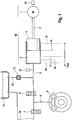
- Fig. 1 shows the simplified principle of an active braking system for a controlled wheel of a hydraulically braked vehicle.
- the inventive method is preferably carried out in an active, externally operable brake system, in which the driver, for example by means of brake pedal travel, a pressure request and this electronically by means of a pressure supply device 50, for example comprising an electric motor or actuator 1, a suitable transmission 2 and a hydraulic pressure chamber 4 limiting piston 3, is implemented by the piston 3 moves by a distance X Akt from a rest position 15 to a position 14, so that a certain volume of the brake fluid from the pressure chamber 4 via line 5 and an initially opened inlet valve 6 in the brake line 8 and thus moved into the wheel brake 9.
- a brake pressure is generated in the wheel brake 9 after overcoming the lining clearance.
- a brake pressure can be reduced by the piston 3 is moved back in the direction of the rest position 15.
- a quick brake pressure reduction as required, for example in the case of ABS control, but is also possible via the valve combination 6, 7 by the inlet valve 6 is closed and the exhaust valve 7 is opened for a certain time. Then brake fluid flows out of the wheel brake 9 via line 8 through the outlet valve 7 and thus via the line 10 in the Brake fluid reservoir 11. This measure of pressure reduction is particularly useful when the pressure chamber 4 serves several wheel brakes in parallel.
- a measuring device 31 is provided, by means of which a position of the pressure supply device 50, which is characteristic of a position or position or position of the actuator 1 and thus of the piston 3 of the pressure supply device 30, is detected.
- Measuring device 31 may, for example, a rotor position angle of the electric motor 1 or a spindle position of a rotation-translation gear or the path X act of the piston 3 from its rest position 15 detect.
- the position of the pressure-providing device 50 can also be determined from other variables, for example based on a model.
- a pressure measuring device 32 is provided, by means of which the actual pressure P V, Ist , ie the pressure in the pressure chamber 4 of the pressure supply device 50 is measured.
- the measured variable X Akt and / or the measured variable P V, Ist are advantageously determined redundantly.
- the corresponding measuring device 31, 32 can be designed to be intrinsically safe, or two redundant measuring devices can accordingly be present.
- each wheel circle preferably has an individual valve pair 6, 7.
- each two wheel brakes are connected to one of two pressure chambers.
- a master cylinder may be arranged so that the pressure generated in the pressure chamber 4 a hydraulic gap, for example in an actuator, is supplied, whereby the master cylinder is actuated.
- the invention is concerned with the task of setting suitable pressures in the pressure chamber. 4
- the need to adjust a predetermined pressure or pressure curve with the aid of a control method results whenever the driver requests a general brake pressure for all wheels of the motor vehicle by operating the brake pedal, or when this pressure request by an assistance function ACC (adaptive cruise control). , Hill start assist (HSA), hill descent control (HDC), etc., or when a particular wheel-specific brake control function becomes active, such as ABS (Anti-lock Braking System), TCS (Traction Control System) or ESP (Electronic Stability Program).
- HSA Hill start assist
- HDC hill descent control
- a particular wheel-specific brake control function becomes active such as ABS (Anti-lock Braking System), TCS (Traction Control System) or ESP (Electronic Stability Program).
- the pressure of the pressure chamber 4 is to be adjusted so that the wheel with the highest brake pressure requirement can be safely supplied with the necessary pressure.
- the dynamics of the pressure to be set or pressure curve applies that in the context of the available dynamics of the actuator 1 is to minimize the time delay between the pressure request and the pressure in the pre-compression chamber 4 is sought. This is especially true when the actuator 1 is at the beginning of the pressure request in its rest position 15 and therefore must first overcome the pad clearance for setting the required pressure. In this case, the actuator initially displaces a volume dependent on the size of the wheel brakes 9 and the adjusted lining clearance, from the pressure chamber 4 into the wheel brakes, in order to apply the linings, for example to the brake disk.
- a linear controller approach it may happen that the full available dynamics of the linear actuator is not utilized in this nominal pressure range.
- a basic structure of a control device 200 for setting a required pressure or pressure curve shows Fig. 2 , It is a pressure regulator 20 which has an actuator speed controller (advantageously engine speed controller). 21 with the interposition of further circuit elements 23 - 25 is superimposed.
- the pressure regulator 20 the result .DELTA.P V is supplied to a subtraction performed in a subtractor 19 between the required pressure setpoint P V, setpoint and the present actual pressure value P V, Ist .
- the output variable of the pressure regulator 20 is the target value for the actuator rotational speed ⁇ Akt, Soll, DR, Crl , which is transferred to the rotational speed controller 21 as an input variable taking into account predetermined minimum and maximum actuator rotational speed values ⁇ Min , ⁇ Max .
- the pressure set point P V, setpoint results from the requirements described in the previous sections.
- the actual pressure value P V, Ist is preferably by means of a pressure sensor (32 in Fig. 1 ). It should be noted that in particular occurring at fast pressure build-ups at the pressure located between the pressure chamber 4 and the wheel brakes 9 valves (eg 6) are also measured by this pressure.
- a proportional acting controller P-controller
- P-controller a proportional acting controller
- the two desired speed components are added together in an adder 23 and supplied to a limiting function 24 for limiting to the minimum or maximum permissible setpoint speed ( ⁇ min , ⁇ max ).
- the output of the pressure regulator 20, 24th is the target value for the engine speed ⁇ Akt, Soll , which is the speed controller 21, 25 is given as input.
- the limited Aktuatorfitiere setpoint ⁇ Akt, Soll is compared in a further subtraction element 25 to form a Aktuatorhopiere setpoint difference .DELTA. ⁇ target with the Aktuatorhopiere actual value ⁇ Akt .
- the Aktuatordusiere setpoint difference ⁇ target is supplied to the above-mentioned speed controller 21 as an input variable whose output corresponds to a setpoint M Akt, Soll, Ctrl applied by the actuator torque.
- the torque setpoint M Akt, Soll, Ctrl is finally limited in a second limiting module 26 to the minimum or maximum permissible torque value M min , M max and gives the torque setpoint M Akt, target for the electric motor.
- Akt of the actuator preferably from the, for example, for commutation purposes available, Aktuatorposition X Akt (measuring device 31 in Fig. 1 ) is determined.
- FIG. 3 an exemplary control device 201 for performing a method according to the invention is shown, which overcomes the above-mentioned disadvantages and significantly improves the control behavior.
- the sensed actual pressure P V, Ist is not considered as the actual pressure value for the pressure control, but a determined value P V, roof is used.
- the actual pressure value P V, roof is determined in the pressure information calculation module (block 40).
- the second signal P V, model is a calculated model pressure, which is determined on the basis of the measured travel X Akt , whereby a static characteristic or function (f (X Akt )) is calculated as the model, the brake system characterizing the dependence of the actual pressure (FIG. P V, Ist ) from the position (X Akt ) of the pressure-providing device 50.
- the weighting factor ⁇ it is determined which signal component is supplied to the pressure control (in the form of the actual pressure value P V, roof ).
- the weighting factor ⁇ is determined as a function of the required setpoint pressure P V, setpoint and advantageously additionally as a function of the required setpoint pressure gradient dP V, setpoint / dt, which results from the time derivative of the setpoint pressure P V, setpoint .
- the required setpoint pressure curve dP V, setpoint / dt is additionally considered.
- FIG Fig. 4 A specification of the embodiment for determining the weighting factor ⁇ , as it may be implemented in module 40, is given in FIG Fig. 4 shown.
- a first parameter ⁇ 1 is determined in block 42 on the basis of a predetermined characteristic as a function of the setpoint pressure P V, desired .
- block 43 is determined by a another predetermined characteristic as a function of the desired pressure derivative dP V, set / dt a second parameter ⁇ 2 determined.
- the actual pressure value P V, roof is calculated on the basis of the weighting factor ⁇ and the relationship of equation (1).
- ⁇ 1 (maximum value), ie it is controlled with the model signal P V, model , so that influenced by congestion effects (too large), measured actual pressures P V, Does not affect the pressure control.
- intermediate values for the parameters ⁇ become in the range between P 1 and P 2 (for P V, setpoint ) and between S 1 and S 2 (for dP V, setpoint / dt) 1 and ⁇ 2 and thus determines the factor ⁇ .
- the pressure value P 2 may be, for example, several 10bar.
- the threshold S 2 may for example be in the range of one or a few 100 bar / sec.
- the required setpoint pressure curve dP V, setpoint / dt is determined in block 41.
- Fig. 5 an exemplary method for determining dP V, target / dt is shown.
- the required setpoint pressure curve dP V, setpoint / dt is determined with the aid of a differentiating filter (block 41b), whereby advantageously an increase limiting function (optional block 41a) is introduced, so that also sudden changes in the pressure requirement P V, desired to a finite setpoint pressure gradient dP V, set / dt lead.
- a jump-shaped pressure request P V, target (solid line in the right-hand diagram P V, setpoint as a function of time t) into a pressure request P V, setpoint with, for example, linear rise (dashed line in the right-hand diagram P V, Soll converted as a function of time t).
- the transition of the pressure control signal P V, roof of the model signal P V, model to the measured pressure value P V, Ist is defined by the weighting factor ⁇ , for example, according to the in Fig. 4 shown arrangement is determined.
- Fig. 2 used controller structure which relates to an extension of the speed feedforward and in Fig. 3 is shown in dashed lines (block 22a and connections).
- an additional engine speed component ⁇ add is provided as a pilot control variable (block 22a), for example, based on the size of the clearance to be overcome (block 22).
- X L depends.
- This additional engine speed component ⁇ add is additively superimposed on a required pressure build-up of the pilot control speed ⁇ Akt, Soll, DR, FFW , as long as the clearance (X L ) has not yet been overcome.
- An exemplary characteristic for the engine speed component ⁇ add as a function of the currently measured actuator travel X Akt is in Fig. 6 shown.
- the size of the additional speed component ⁇ add can also be predetermined (additionally) as a function of the requested setpoint pressure gradient dP V, setpoint / dt.
Claims (12)
- Procédé de réglage d'un système de freinage pour véhicules automobiles, comprenant un frein de roue (9) à commande hydraulique (9), qui peut être actionné au moyen d'un dispositif d'alimentation en pression (50) à commande électronique, qui comprend un agencement cylindre-piston avec un espace de pression hydraulique (4), dont le piston (3) peut être déplacé par un actionneur électromécanique (1), de telle sorte qu'une valeur de pression de consigne prédéfinie (PV,Soll) puisse être ajustée dans l'espace de pression hydraulique (4), une position (XAkt) du dispositif d'alimentation en pression (50) étant détectée (31), et une pression instantanée (PV,Ist) du dispositif d'alimentation en pression (50) étant déterminée au moyen d'un dispositif de mesure (32), des grandeurs de réglage (ωAkt,Soll, MAkt,Soll) pour l'actionneur électromécanique (1) étant formées à l'aide de la valeur de pression de consigne prédéfinie (PV,Soll) et d'une valeur de pression instantanée (PV,Dach), caractérisé en ce que la valeur de pression instantanée (PV,Dach) est déterminée en fonction de la valeur de pression de consigne (PV,Soll) par addition pondérée de la pression instantanée (PV,Ist) et d'un modèle de pression (PV,Mod) calculé à partir d'une position actuelle (XAkt) du dispositif d'alimentation en pression.
- Procédé selon la revendication 1, caractérisé en ce que la valeur de pression instantanée (PV,Dach) est déterminée ou sélectionnée (40, 43) en fonction de la dérivée dans le temps de la valeur de pression de consigne prédéfinie (dPV,Soll/dt).
- Procédé selon la revendication 1 ou 2, caractérisé en ce qu'un facteur de pondération (À) pour l'addition pondérée est déterminé (42) en fonction de la valeur de pression de consigne (PV,Soll).
- Procédé selon la revendication 3, caractérisé en ce que le facteur de pondération (À) pour l'addition pondérée est déterminé (43) en fonction de la dérivée dans le temps de la valeur de pression de consigne prédéfinie (dPV,Soll/dt).
- Procédé selon l'une quelconque des revendications 1 à 4, caractérisé en ce que la valeur de pression instantanée (PV,Dach) est identique à la pression instantanée (PV,Ist), lorsque la valeur de pression de consigne (PV,Soll) est située au-dessus d'une valeur de pression seuil prédéfinie (P2).
- Procédé selon l'une quelconque des revendications 2 à 5, caractérisé en ce que la dérivée dans le temps de la valeur de pression de consigne prédéfinie (dPV,Soll/dt) est comparée à une valeur seuil prédéfinie (S1, S2) lorsque la valeur de pression de consigne (PV,Soll) est située en-dessous de la valeur de pression seuil prédéfinie (P2).
- Procédé selon l'une quelconque des revendications 1 à 6, caractérisé en ce que la valeur de pression instantanée (PV,Dach) est identique au modèle de pression (PV,Mod) lorsque la dérivée dans le temps de la valeur de pression de consigne prédéfinie (dPV,Soll/dt) est située au-dessus de la valeur de pression seuil prédéfinie (S2) et que la valeur de pression de consigne (PV,Soll) est située en-dessous d'une deuxième valeur de pression seuil prédéfinie (P1).
- Procédé selon l'une quelconque des revendications 1 à 7, caractérisé en ce que le modèle de pression (PV,Mod) est calculé en fonction d'une caractéristique ou d'une fonction prédéfinie (f(XAkt)) qui constitue la dépendance de la pression instantanée de la position (XAkt) du dispositif d'alimentation en pression (50) caractérisant l'installation de freinage (PV,Ist).
- Procédé selon l'une quelconque des revendications 1 à 8, caractérisé en ce que la valeur de pression de consigne (PV,Soll) et la valeur de pression instantanée (PV,Dach) sont envoyées à un régulateur de pression (20) avec un régulateur de vitesse aval (21), une commande de vitesse pilote (22a) étant prévue, dont la grandeur de départ (ωadd) est déterminé en fonction de la position actuelle (XAkt) du dispositif d'alimentation en pression (50) .
- Dispositif de réglage (201) qui forme, en fonction d'une valeur de pression instantanée (PV,Dach) et d'une valeur de pression de consigne prédéfinie (PV,soll), des grandeurs de réglage (ωAkt,Soll, MAkt,Soll) pour un actionneur électromécanique (1), comprenant un régulateur de pression (20) et un régulateur de vitesse (21) en aval du régulateur de pression, la grandeur de réglage (ωAkt,Soll) représentant une valeur de vitesse de consigne de l'actionneur et une valeur instantanée (ωAkt) de la vitesse de l'actionneur étant envoyées au régulateur de vitesse (21) en tant que grandeurs d'entrée, caractérisé en ce que des moyens (40) sont prévus pour déterminer la valeur de pression instantanée (PV,Dach) selon l'une quelconque des revendications 1 à 9 et l'envoyer au régulateur de pression (20).
- Dispositif de réglage (201) selon la revendication 10, caractérisé en ce que le régulateur de pression (20) émet une première valeur de vitesse de consigne de l'actionneur (ωAkt,Soll,Ctrl), une deuxième valeur de vitesse de consigne de l'actionneur (ωAkt,Soll,DR,FFW) est déterminée (22) à partir de la valeur de pression de consigne (PV,Soll) en particulier de la dérivée dans le temps de la valeur de pression de consigne, une troisième valeur de vitesse de consigne de l'actionneur (ωadd) est déterminée (22a) au moins à partir de la position (XAkt) du dispositif d'alimentation en pression (50) et la grandeur de réglage (ωAkt,Soll) représentant la valeur de vitesse de consigne de l'actionneur pour le régulateur de vitesse (21) est déterminée à partir de la première, la deuxième et de la troisième valeur de vitesse de consigne de l'actionneur (ωAkt,Soll,DR,Ctrl, ωAkt,Soll,DR,FFW, ωadd).
- Installation de freinage pour véhicules automobiles comprenant au moins un frein de roue (9) à commande hydraulique, un dispositif d'alimentation en pression (50) à commande électronique pour l'actionnement du frein de roue (9) qui comprend un agencement cylindre-piston avec un espace de pression hydraulique (4), dont le piston (3) peut être déplacé par un actionneur électromécanique (1), un dispositif de mesure (32) pour déterminer une valeur de pression instantanée (PV,Ist) dispositif d'alimentation en pression (50), des moyens qui déterminent, directement ou indirectement, une position (XAkt) du dispositif d'alimentation en pression (50), en particulier de l'actionneur (1), et une unité de commande de réglage électronique pour commander l'actionneur électromécanique (1), caractérisée en ce que l'unité de commande de réglage électronique (33) comprend un dispositif de réglage (201) selon la revendication 10 ou 11, qui, en fonction d'une valeur de pression instantanée (PV,Dach) et de la valeur de pression de consigne prédéfinie (PV,Soll), forme des grandeurs de réglage (ωAkt,Soll, MAkt,Soll) pour l'actionneur électromécanique (1), des moyens (40) étant prévus au moyen desquels un procédé selon l'une quelconque des revendications 1 à 9 est mis en oeuvre.
Applications Claiming Priority (3)
| Application Number | Priority Date | Filing Date | Title |
|---|---|---|---|
| DE102012217752 | 2012-09-28 | ||
| DE102013216157.3A DE102013216157A1 (de) | 2012-09-28 | 2013-08-14 | Verfahren zur Regelung einer Bremsanlage für Kraftfahrzeuge |
| PCT/EP2013/068577 WO2014048705A1 (fr) | 2012-09-28 | 2013-09-09 | Procédé de commande d'un système de freinage pour véhicules automobiles |
Publications (2)
| Publication Number | Publication Date |
|---|---|
| EP2900529A1 EP2900529A1 (fr) | 2015-08-05 |
| EP2900529B1 true EP2900529B1 (fr) | 2018-08-29 |
Family
ID=50276459
Family Applications (1)
| Application Number | Title | Priority Date | Filing Date |
|---|---|---|---|
| EP13759516.1A Active EP2900529B1 (fr) | 2012-09-28 | 2013-09-09 | Procédé de commande d'un système de freinage pour véhicules automobiles |
Country Status (6)
| Country | Link |
|---|---|
| US (1) | US9566962B2 (fr) |
| EP (1) | EP2900529B1 (fr) |
| KR (1) | KR102083049B1 (fr) |
| CN (1) | CN104684773B (fr) |
| DE (1) | DE102013216157A1 (fr) |
| WO (1) | WO2014048705A1 (fr) |
Families Citing this family (15)
| Publication number | Priority date | Publication date | Assignee | Title |
|---|---|---|---|---|
| DE102012025291A1 (de) * | 2012-12-21 | 2014-06-26 | Lucas Automotive Gmbh | Elektrohydraulische Fahrzeug-Bremsanlage und Verfahren zum Betreiben derselben |
| DE102013216329A1 (de) * | 2013-08-19 | 2015-02-19 | Continental Teves Ag & Co. Ohg | Verfahren und Vorrichtung zur Regelung eines Bremssystems |
| DE102014215297A1 (de) | 2014-08-04 | 2016-02-04 | Continental Teves Ag & Co. Ohg | Regelschaltung zur Regelung sowie Schaltungsanordnung zur Steuerung einer Bremsanlage für Kraftfahrzeuge |
| KR101734041B1 (ko) * | 2015-11-09 | 2017-05-24 | 주식회사 만도 | 압력 제어 장치 및 그 압력 제어 방법 |
| CN105383470A (zh) * | 2015-11-23 | 2016-03-09 | 浙江万向精工有限公司 | 一种基于压力解耦控制的wbs压力控制系统及控制方法 |
| CN106184168B (zh) * | 2016-07-29 | 2019-02-05 | 天津英创汇智汽车技术有限公司 | 一种汽车制动系统及制动压力控制方法 |
| DE102016226324A1 (de) * | 2016-12-29 | 2018-07-05 | Robert Bosch Gmbh | Auswerteelektronik und Verfahren zum Schätzen eines Hauptbremszylinderdrucks in einem mit einem elektromechanischen Bremskraftverstärker ausgestatteten Bremssystem eines Fahrzeugs |
| US11535211B2 (en) * | 2017-12-31 | 2022-12-27 | ZF Active Safety US Inc. | Vehicle brake system and method of detecting piston location of a plunger assembly |
| US10894536B2 (en) * | 2018-05-23 | 2021-01-19 | Deere & Company | Service brake actuation using a linear actuator |
| US11015729B2 (en) | 2019-05-13 | 2021-05-25 | The Boeing Company | System for determining the stack closure pressure of a brake stack |
| BR102020006561A2 (pt) * | 2019-05-13 | 2021-02-17 | The Boeing Company | sistema de freio, aeronave que tem o sistema de freio e método para determinar a pressão de fechamento do conjunto para o conjunto de freio do sistema de freio |
| US11345465B2 (en) | 2019-05-13 | 2022-05-31 | The Boeing Company | System for determining the stack closure pressure of a brake stack |
| CN110920595B (zh) * | 2019-10-28 | 2020-12-08 | 上海汇众汽车制造有限公司 | 电卡钳制动间隙估算方法 |
| DE102020200908A1 (de) * | 2020-01-27 | 2021-07-29 | Robert Bosch Gesellschaft mit beschränkter Haftung | Verfahren zum Regeln einer kinematischen Größe eines Kraftfahrzeugs |
| CN114056308B (zh) * | 2022-01-17 | 2022-04-22 | 万向钱潮股份有限公司 | 基于线控助力器的多轴商用车制动力控制方法与分配方法 |
Family Cites Families (19)
| Publication number | Priority date | Publication date | Assignee | Title |
|---|---|---|---|---|
| DE4007360A1 (de) * | 1990-03-08 | 1991-09-12 | Daimler Benz Ag | Verfahren zur bremsdruckverteilung auf die achsen eines kraftfahrzeugs mit abs-druckmittelbremse |
| DE4335769C1 (de) * | 1993-10-20 | 1994-12-08 | Daimler Benz Ag | Bremsdruck-Steuereinrichtung für ein Straßenfahrzeug |
| DE19543583C1 (de) * | 1995-11-22 | 1997-02-06 | Daimler Benz Ag | Bremsdruck-Steuerungseinrichtung für ein Straßenfahrzeug mit elektrohydraulischer Mehrkreis-Bremsanlage |
| DE19807366A1 (de) * | 1998-02-21 | 1999-08-26 | Bosch Gmbh Robert | Verfahren und Vorrichtung zur Steuerung einer Bremsanlage |
| EP1093427B1 (fr) * | 1998-07-09 | 2004-11-10 | Continental Teves AG & Co. oHG | Procede et dispositif pour ajuster la pression de freinage et pour ouvrir une soupape d'admission |
| JP2004537462A (ja) * | 2001-08-10 | 2004-12-16 | コンティネンタル・テーベス・アクチエンゲゼルシヤフト・ウント・コンパニー・オッフェネ・ハンデルスゲゼルシヤフト | トラクションスリップコントロールシステムの制御状態を改善する方法 |
| DE102006002352A1 (de) * | 2005-11-29 | 2007-05-31 | Robert Bosch Gmbh | Verfahren zur Durchführung einer Stillstandshaltefunktion bei einem Kraftfahrzeug |
| DE102006020520B4 (de) * | 2006-05-03 | 2015-05-21 | Robert Bosch Gmbh | Regelung des Bremsdrucks mittels eines Druckbegrenzungsventils |
| DE102006040424A1 (de) | 2006-08-29 | 2008-03-06 | Continental Teves Ag & Co. Ohg | Bremssystem für Kraftfahrzeuge |
| DE102008003798A1 (de) * | 2008-01-10 | 2009-07-16 | Robert Bosch Gmbh | Verfahren für die Steuerung eines Magnetventils |
| DE102008002596A1 (de) * | 2008-05-20 | 2009-11-26 | Robert Bosch Gmbh | Bremsanlage und Verfahren zum Betreiben einer Bremsanlage |
| DE102009033499A1 (de) * | 2008-07-18 | 2010-01-21 | Continental Teves Ag & Co. Ohg | Bremsanlage für Kraftfahrzeuge |
| DE102010008033A1 (de) * | 2010-02-13 | 2011-08-18 | Ipgate Ag | Bremssystem mit Druckmodell und Priorisierungseinrichtung |
| DE102011076952A1 (de) * | 2010-06-10 | 2011-12-29 | Continental Teves Ag & Co. Ohg | Verfahren und Regelschaltung zur Regelung eines Bremssystems für Kraftfahrzeuge |
| DE102011076675A1 (de) | 2010-06-10 | 2011-12-15 | Continental Teves Ag & Co. Ohg | Verfahren und Vorrichtung zur Regelung eines elektrohydraulischen Bremssystems für Kraftfahrzeuge |
| DE102012200705A1 (de) * | 2011-01-27 | 2012-08-02 | Continental Teves Ag & Co. Ohg | Verfahren und Vorrichtung zur Regelung einer elektrohydraulischen Bremsanlage |
| DE102012200494B4 (de) * | 2011-01-27 | 2020-07-23 | Continental Teves Ag & Co. Ohg | Verfahren zur Regelung einer Bremsanlage für Kraftfahrzeuge sowie Bremsanlage |
| DE102011080404A1 (de) * | 2011-08-04 | 2013-02-07 | Robert Bosch Gmbh | Verfahren zum Festlegen eines Funktionszustands eines Druckaufbauventils und Funktionsüberwachungsvorrichtung für ein Druckaufbauventil einer hydraulischen Bremskraftverstärkervorrichtung |
| DE102013224967A1 (de) * | 2013-06-05 | 2014-12-11 | Continental Teves Ag & Co. Ohg | Verfahren zur Regelung eines elektromechanischen Aktuators sowie Regelvorrichtung |
-
2013
- 2013-08-14 DE DE102013216157.3A patent/DE102013216157A1/de not_active Withdrawn
- 2013-09-09 US US14/431,151 patent/US9566962B2/en active Active
- 2013-09-09 CN CN201380050579.6A patent/CN104684773B/zh active Active
- 2013-09-09 EP EP13759516.1A patent/EP2900529B1/fr active Active
- 2013-09-09 KR KR1020157011093A patent/KR102083049B1/ko active IP Right Grant
- 2013-09-09 WO PCT/EP2013/068577 patent/WO2014048705A1/fr active Application Filing
Also Published As
| Publication number | Publication date |
|---|---|
| WO2014048705A1 (fr) | 2014-04-03 |
| CN104684773B (zh) | 2017-09-15 |
| KR20150062170A (ko) | 2015-06-05 |
| US20150239438A1 (en) | 2015-08-27 |
| CN104684773A (zh) | 2015-06-03 |
| US9566962B2 (en) | 2017-02-14 |
| EP2900529A1 (fr) | 2015-08-05 |
| DE102013216157A1 (de) | 2014-04-03 |
| KR102083049B1 (ko) | 2020-04-14 |
Similar Documents
| Publication | Publication Date | Title |
|---|---|---|
| EP2900529B1 (fr) | Procédé de commande d'un système de freinage pour véhicules automobiles | |
| EP3003803B1 (fr) | Procédé permettant le réglage d'un actionneur électromécanique et dispositif de réglage | |
| EP2580095B1 (fr) | Procédé et dispositif pour réguler un système de freinage électrohydraulique destiné à des véhicules à moteur | |
| EP2822825B1 (fr) | Procédé de fonctionnement d'un système de freinage et appareil de freinage correspondant | |
| EP2580096B1 (fr) | Procédé et circuit de régulation pour réguler une installation de freinage d'un véhicule à moteur | |
| EP2668075B1 (fr) | Procédé et dispositif pour régler un système de freinage électrohydraulique | |
| EP2613987B1 (fr) | Procede de ajustement d'un frein de stationnement, appareil de commande pour celui-ci et frein de stationnement dans un vehicule aces un tel appareil de commande | |
| EP3116758B1 (fr) | Procédé d'étalonnage d'un système de freinage électrohydraulique de véhicule automobile et dispositif d'étalonnage | |
| EP0752939B1 (fr) | Procede pour faire fonctionner un systeme d'actionnement de freins a regulation electronique | |
| EP1807294B1 (fr) | Procede pour calculer le courant de commande d'une soupape hydraulique a commande electrique | |
| EP3353025B1 (fr) | Procédé de réglage des pressions de freinage d'un véhicule automobile, système de freinage pour la mise en oeuvre de ce procédé et véhicule à moteur doté d'un tel système de freinage | |
| EP3036136B1 (fr) | Procédé et dispositif de régulation d'un système de freinage | |
| EP2934972B1 (fr) | Procédé et ensemble d'assistance au freinage pour un système de freinage électrohydraulique d'un véhicule automobile | |
| EP2718158B1 (fr) | Procédé permettant de faire fonctionner un système de freinage et système de freinage | |
| WO2015036156A1 (fr) | Procédé de commande d'un amplificateur de freinage, appareil de commande pour mettre en œuvre le procédé et système de freinage comportant l'amplificateur de freinage et l'appareil de commande | |
| DE102012200494B4 (de) | Verfahren zur Regelung einer Bremsanlage für Kraftfahrzeuge sowie Bremsanlage | |
| DE102016220752A1 (de) | Verfahren zum Betreiben eines Bremssystems und Bremssystem | |
| EP3419873A1 (fr) | Procédé pour faire fonctionner un système de freinage pour véhicules à moteur et système de freinage | |
| DE102016203117A1 (de) | Verfahren zum Betreiben einer Bremsanlage und Bremsanlage | |
| DE102004060053A1 (de) | Servolenkung und Verfahren zur Fahrerunterstützung bei seiner Lenktätigkeit | |
| DE10325266A1 (de) | Bremsanlage und Verfahren für Kraftfahrzeuge | |
| DE102012200174A1 (de) | Verfahren zur Bestimmung eines Drucksollwertes für eine Bremsanlage für Kraftfahrzeuge und Bremsanlage | |
| DE102015215926A1 (de) | Verfahren zur Regelung einer Bremsanlage für Kraftfahrzeuge, Regelvorrichtung und Bremsanlage | |
| WO2016020228A1 (fr) | Circuit de régulation et ensemble de circuit pour la commande d'un système de freinage pour véhicules automobiles | |
| DE102017202361A1 (de) | Verfahren zum Betreiben einer Bremsanlage und Bremsanlage |
Legal Events
| Date | Code | Title | Description |
|---|---|---|---|
| PUAI | Public reference made under article 153(3) epc to a published international application that has entered the european phase |
Free format text: ORIGINAL CODE: 0009012 |
|
| 17P | Request for examination filed |
Effective date: 20150428 |
|
| AK | Designated contracting states |
Kind code of ref document: A1 Designated state(s): AL AT BE BG CH CY CZ DE DK EE ES FI FR GB GR HR HU IE IS IT LI LT LU LV MC MK MT NL NO PL PT RO RS SE SI SK SM TR |
|
| AX | Request for extension of the european patent |
Extension state: BA ME |
|
| DAX | Request for extension of the european patent (deleted) | ||
| GRAP | Despatch of communication of intention to grant a patent |
Free format text: ORIGINAL CODE: EPIDOSNIGR1 |
|
| INTG | Intention to grant announced |
Effective date: 20180424 |
|
| GRAS | Grant fee paid |
Free format text: ORIGINAL CODE: EPIDOSNIGR3 |
|
| GRAA | (expected) grant |
Free format text: ORIGINAL CODE: 0009210 |
|
| AK | Designated contracting states |
Kind code of ref document: B1 Designated state(s): AL AT BE BG CH CY CZ DE DK EE ES FI FR GB GR HR HU IE IS IT LI LT LU LV MC MK MT NL NO PL PT RO RS SE SI SK SM TR |
|
| REG | Reference to a national code |
Ref country code: GB Ref legal event code: FG4D Free format text: NOT ENGLISH |
|
| REG | Reference to a national code |
Ref country code: CH Ref legal event code: EP |
|
| REG | Reference to a national code |
Ref country code: AT Ref legal event code: REF Ref document number: 1034753 Country of ref document: AT Kind code of ref document: T Effective date: 20180915 |
|
| RAP2 | Party data changed (patent owner data changed or rights of a patent transferred) |
Owner name: CONTINENTAL TEVES AG & CO. OHG |
|
| REG | Reference to a national code |
Ref country code: IE Ref legal event code: FG4D Free format text: LANGUAGE OF EP DOCUMENT: GERMAN |
|
| REG | Reference to a national code |
Ref country code: DE Ref legal event code: R096 Ref document number: 502013010974 Country of ref document: DE |
|
| REG | Reference to a national code |
Ref country code: FR Ref legal event code: PLFP Year of fee payment: 6 |
|
| REG | Reference to a national code |
Ref country code: NL Ref legal event code: MP Effective date: 20180829 |
|
| REG | Reference to a national code |
Ref country code: LT Ref legal event code: MG4D |
|
| PG25 | Lapsed in a contracting state [announced via postgrant information from national office to epo] |
Ref country code: FI Free format text: LAPSE BECAUSE OF FAILURE TO SUBMIT A TRANSLATION OF THE DESCRIPTION OR TO PAY THE FEE WITHIN THE PRESCRIBED TIME-LIMIT Effective date: 20180829 Ref country code: NO Free format text: LAPSE BECAUSE OF FAILURE TO SUBMIT A TRANSLATION OF THE DESCRIPTION OR TO PAY THE FEE WITHIN THE PRESCRIBED TIME-LIMIT Effective date: 20181129 Ref country code: IS Free format text: LAPSE BECAUSE OF FAILURE TO SUBMIT A TRANSLATION OF THE DESCRIPTION OR TO PAY THE FEE WITHIN THE PRESCRIBED TIME-LIMIT Effective date: 20181229 Ref country code: SE Free format text: LAPSE BECAUSE OF FAILURE TO SUBMIT A TRANSLATION OF THE DESCRIPTION OR TO PAY THE FEE WITHIN THE PRESCRIBED TIME-LIMIT Effective date: 20180829 Ref country code: RS Free format text: LAPSE BECAUSE OF FAILURE TO SUBMIT A TRANSLATION OF THE DESCRIPTION OR TO PAY THE FEE WITHIN THE PRESCRIBED TIME-LIMIT Effective date: 20180829 Ref country code: LT Free format text: LAPSE BECAUSE OF FAILURE TO SUBMIT A TRANSLATION OF THE DESCRIPTION OR TO PAY THE FEE WITHIN THE PRESCRIBED TIME-LIMIT Effective date: 20180829 Ref country code: NL Free format text: LAPSE BECAUSE OF FAILURE TO SUBMIT A TRANSLATION OF THE DESCRIPTION OR TO PAY THE FEE WITHIN THE PRESCRIBED TIME-LIMIT Effective date: 20180829 Ref country code: BG Free format text: LAPSE BECAUSE OF FAILURE TO SUBMIT A TRANSLATION OF THE DESCRIPTION OR TO PAY THE FEE WITHIN THE PRESCRIBED TIME-LIMIT Effective date: 20181129 Ref country code: GR Free format text: LAPSE BECAUSE OF FAILURE TO SUBMIT A TRANSLATION OF THE DESCRIPTION OR TO PAY THE FEE WITHIN THE PRESCRIBED TIME-LIMIT Effective date: 20181130 |
|
| PG25 | Lapsed in a contracting state [announced via postgrant information from national office to epo] |
Ref country code: AL Free format text: LAPSE BECAUSE OF FAILURE TO SUBMIT A TRANSLATION OF THE DESCRIPTION OR TO PAY THE FEE WITHIN THE PRESCRIBED TIME-LIMIT Effective date: 20180829 Ref country code: LV Free format text: LAPSE BECAUSE OF FAILURE TO SUBMIT A TRANSLATION OF THE DESCRIPTION OR TO PAY THE FEE WITHIN THE PRESCRIBED TIME-LIMIT Effective date: 20180829 Ref country code: HR Free format text: LAPSE BECAUSE OF FAILURE TO SUBMIT A TRANSLATION OF THE DESCRIPTION OR TO PAY THE FEE WITHIN THE PRESCRIBED TIME-LIMIT Effective date: 20180829 |
|
| PG25 | Lapsed in a contracting state [announced via postgrant information from national office to epo] |
Ref country code: ES Free format text: LAPSE BECAUSE OF FAILURE TO SUBMIT A TRANSLATION OF THE DESCRIPTION OR TO PAY THE FEE WITHIN THE PRESCRIBED TIME-LIMIT Effective date: 20180829 Ref country code: PL Free format text: LAPSE BECAUSE OF FAILURE TO SUBMIT A TRANSLATION OF THE DESCRIPTION OR TO PAY THE FEE WITHIN THE PRESCRIBED TIME-LIMIT Effective date: 20180829 Ref country code: RO Free format text: LAPSE BECAUSE OF FAILURE TO SUBMIT A TRANSLATION OF THE DESCRIPTION OR TO PAY THE FEE WITHIN THE PRESCRIBED TIME-LIMIT Effective date: 20180829 Ref country code: CZ Free format text: LAPSE BECAUSE OF FAILURE TO SUBMIT A TRANSLATION OF THE DESCRIPTION OR TO PAY THE FEE WITHIN THE PRESCRIBED TIME-LIMIT Effective date: 20180829 Ref country code: IT Free format text: LAPSE BECAUSE OF FAILURE TO SUBMIT A TRANSLATION OF THE DESCRIPTION OR TO PAY THE FEE WITHIN THE PRESCRIBED TIME-LIMIT Effective date: 20180829 Ref country code: EE Free format text: LAPSE BECAUSE OF FAILURE TO SUBMIT A TRANSLATION OF THE DESCRIPTION OR TO PAY THE FEE WITHIN THE PRESCRIBED TIME-LIMIT Effective date: 20180829 |
|
| REG | Reference to a national code |
Ref country code: CH Ref legal event code: PL |
|
| PG25 | Lapsed in a contracting state [announced via postgrant information from national office to epo] |
Ref country code: DK Free format text: LAPSE BECAUSE OF FAILURE TO SUBMIT A TRANSLATION OF THE DESCRIPTION OR TO PAY THE FEE WITHIN THE PRESCRIBED TIME-LIMIT Effective date: 20180829 Ref country code: SM Free format text: LAPSE BECAUSE OF FAILURE TO SUBMIT A TRANSLATION OF THE DESCRIPTION OR TO PAY THE FEE WITHIN THE PRESCRIBED TIME-LIMIT Effective date: 20180829 Ref country code: SK Free format text: LAPSE BECAUSE OF FAILURE TO SUBMIT A TRANSLATION OF THE DESCRIPTION OR TO PAY THE FEE WITHIN THE PRESCRIBED TIME-LIMIT Effective date: 20180829 |
|
| REG | Reference to a national code |
Ref country code: DE Ref legal event code: R097 Ref document number: 502013010974 Country of ref document: DE |
|
| REG | Reference to a national code |
Ref country code: BE Ref legal event code: MM Effective date: 20180930 |
|
| REG | Reference to a national code |
Ref country code: IE Ref legal event code: MM4A |
|
| PG25 | Lapsed in a contracting state [announced via postgrant information from national office to epo] |
Ref country code: LU Free format text: LAPSE BECAUSE OF NON-PAYMENT OF DUE FEES Effective date: 20180909 Ref country code: MC Free format text: LAPSE BECAUSE OF FAILURE TO SUBMIT A TRANSLATION OF THE DESCRIPTION OR TO PAY THE FEE WITHIN THE PRESCRIBED TIME-LIMIT Effective date: 20180829 |
|
| PLBE | No opposition filed within time limit |
Free format text: ORIGINAL CODE: 0009261 |
|
| STAA | Information on the status of an ep patent application or granted ep patent |
Free format text: STATUS: NO OPPOSITION FILED WITHIN TIME LIMIT |
|
| GBPC | Gb: european patent ceased through non-payment of renewal fee |
Effective date: 20181129 |
|
| PG25 | Lapsed in a contracting state [announced via postgrant information from national office to epo] |
Ref country code: IE Free format text: LAPSE BECAUSE OF NON-PAYMENT OF DUE FEES Effective date: 20180909 |
|
| 26N | No opposition filed |
Effective date: 20190531 |
|
| PG25 | Lapsed in a contracting state [announced via postgrant information from national office to epo] |
Ref country code: CH Free format text: LAPSE BECAUSE OF NON-PAYMENT OF DUE FEES Effective date: 20180930 Ref country code: SI Free format text: LAPSE BECAUSE OF FAILURE TO SUBMIT A TRANSLATION OF THE DESCRIPTION OR TO PAY THE FEE WITHIN THE PRESCRIBED TIME-LIMIT Effective date: 20180829 Ref country code: BE Free format text: LAPSE BECAUSE OF NON-PAYMENT OF DUE FEES Effective date: 20180930 Ref country code: LI Free format text: LAPSE BECAUSE OF NON-PAYMENT OF DUE FEES Effective date: 20180930 |
|
| REG | Reference to a national code |
Ref country code: AT Ref legal event code: MM01 Ref document number: 1034753 Country of ref document: AT Kind code of ref document: T Effective date: 20180909 |
|
| PG25 | Lapsed in a contracting state [announced via postgrant information from national office to epo] |
Ref country code: GB Free format text: LAPSE BECAUSE OF NON-PAYMENT OF DUE FEES Effective date: 20181129 |
|
| PG25 | Lapsed in a contracting state [announced via postgrant information from national office to epo] |
Ref country code: MT Free format text: LAPSE BECAUSE OF FAILURE TO SUBMIT A TRANSLATION OF THE DESCRIPTION OR TO PAY THE FEE WITHIN THE PRESCRIBED TIME-LIMIT Effective date: 20180829 Ref country code: AT Free format text: LAPSE BECAUSE OF NON-PAYMENT OF DUE FEES Effective date: 20180909 |
|
| PG25 | Lapsed in a contracting state [announced via postgrant information from national office to epo] |
Ref country code: TR Free format text: LAPSE BECAUSE OF FAILURE TO SUBMIT A TRANSLATION OF THE DESCRIPTION OR TO PAY THE FEE WITHIN THE PRESCRIBED TIME-LIMIT Effective date: 20180829 |
|
| PG25 | Lapsed in a contracting state [announced via postgrant information from national office to epo] |
Ref country code: PT Free format text: LAPSE BECAUSE OF FAILURE TO SUBMIT A TRANSLATION OF THE DESCRIPTION OR TO PAY THE FEE WITHIN THE PRESCRIBED TIME-LIMIT Effective date: 20180829 |
|
| PG25 | Lapsed in a contracting state [announced via postgrant information from national office to epo] |
Ref country code: CY Free format text: LAPSE BECAUSE OF FAILURE TO SUBMIT A TRANSLATION OF THE DESCRIPTION OR TO PAY THE FEE WITHIN THE PRESCRIBED TIME-LIMIT Effective date: 20180829 Ref country code: HU Free format text: LAPSE BECAUSE OF FAILURE TO SUBMIT A TRANSLATION OF THE DESCRIPTION OR TO PAY THE FEE WITHIN THE PRESCRIBED TIME-LIMIT; INVALID AB INITIO Effective date: 20130909 Ref country code: MK Free format text: LAPSE BECAUSE OF NON-PAYMENT OF DUE FEES Effective date: 20180829 |
|
| REG | Reference to a national code |
Ref country code: DE Ref legal event code: R081 Ref document number: 502013010974 Country of ref document: DE Owner name: CONTINENTAL AUTOMOTIVE TECHNOLOGIES GMBH, DE Free format text: FORMER OWNER: CONTINENTAL TEVES AG & CO. OHG, 60488 FRANKFURT, DE |
|
| PGFP | Annual fee paid to national office [announced via postgrant information from national office to epo] |
Ref country code: FR Payment date: 20220922 Year of fee payment: 10 |
|
| P01 | Opt-out of the competence of the unified patent court (upc) registered |
Effective date: 20230522 |
|
| PGFP | Annual fee paid to national office [announced via postgrant information from national office to epo] |
Ref country code: DE Payment date: 20230930 Year of fee payment: 11 |
|
| REG | Reference to a national code |
Ref country code: DE Ref legal event code: R081 Ref document number: 502013010974 Country of ref document: DE Owner name: CONTINENTAL AUTOMOTIVE TECHNOLOGIES GMBH, DE Free format text: FORMER OWNER: CONTINENTAL AUTOMOTIVE TECHNOLOGIES GMBH, 30165 HANNOVER, DE |