EP2900103B1 - Umbrella - Google Patents
Umbrella Download PDFInfo
- Publication number
- EP2900103B1 EP2900103B1 EP13774769.7A EP13774769A EP2900103B1 EP 2900103 B1 EP2900103 B1 EP 2900103B1 EP 13774769 A EP13774769 A EP 13774769A EP 2900103 B1 EP2900103 B1 EP 2900103B1
- Authority
- EP
- European Patent Office
- Prior art keywords
- canopy
- sliding
- support
- sliding support
- umbrella
- Prior art date
- Legal status (The legal status is an assumption and is not a legal conclusion. Google has not performed a legal analysis and makes no representation as to the accuracy of the status listed.)
- Active
Links
Images


Classifications
-
- A—HUMAN NECESSITIES
- A45—HAND OR TRAVELLING ARTICLES
- A45B—WALKING STICKS; UMBRELLAS; LADIES' OR LIKE FANS
- A45B25/00—Details of umbrellas
- A45B25/06—Umbrella runners
-
- A—HUMAN NECESSITIES
- A45—HAND OR TRAVELLING ARTICLES
- A45B—WALKING STICKS; UMBRELLAS; LADIES' OR LIKE FANS
- A45B19/00—Special folding or telescoping of umbrellas
- A45B19/06—Special folding or telescoping of umbrellas with telescopic ribs
-
- A—HUMAN NECESSITIES
- A45—HAND OR TRAVELLING ARTICLES
- A45B—WALKING STICKS; UMBRELLAS; LADIES' OR LIKE FANS
- A45B19/00—Special folding or telescoping of umbrellas
-
- A—HUMAN NECESSITIES
- A45—HAND OR TRAVELLING ARTICLES
- A45B—WALKING STICKS; UMBRELLAS; LADIES' OR LIKE FANS
- A45B25/00—Details of umbrellas
- A45B25/02—Umbrella frames
-
- A—HUMAN NECESSITIES
- A45—HAND OR TRAVELLING ARTICLES
- A45B—WALKING STICKS; UMBRELLAS; LADIES' OR LIKE FANS
- A45B19/00—Special folding or telescoping of umbrellas
- A45B2019/008—Umbrellas having upward pointing rib ends when closed, i.e. the lower dry side of the cover facing the outside when closed
Definitions
- the present invention primarily relates, but is not limited, to umbrellas. It is particularly applicable to umbrellas in which the umbrella canopy folds inside out and preferably into the umbrella handle or a sleeve attached to the handle for storage. This folding arrangement keeps the wet side (i.e. the outside face) of the umbrella canopy away from the user and once folded, retains any remaining water within the wet side of the canopy and prevents it from dripping out.
- an umbrella casing, cover or sleeve is so arranged to be an extension of the handle grip, to provide further seal against leakage.
- CN101711621 (Trade K K U ) describes a traditional golf style umbrella.
- the umbrella described folds away after use so that the wet external surface is internal in the closed configuration.
- the problem with this is that the closed umbrella is longer in length that the closed umbrella.
- the umbrella canopy In addition in order for the umbrella canopy to be able to complete the movements described it would need to have a canopy which is much larger than a standard canopy and fit loosely on the canopy framework of the umbrella in the open position, as well as needing someone with really long arms to operate it!.
- GB2346556 and GB2473936 attempt to solve the same problem in a compact style umbrella which when folded is the same size as a standard compact style umbrella.
- this suffers from the same problem that in order for the umbrella canopy to be able to complete the movements described it would need to have a canopy which is much larger than a standard canopy and fit loosely on the canopy framework of the umbrella in the open position.
- US3837352 (TELESCO BROPHEY LTD ) describes an umbrella having a frame and a canopy which is open to an approximate elliptical shape, such as to accommodate two people.
- the frame includes dome ribs hinged to a crown wherein the dome ribs have extended lengths along the major axis of the so-formed ellipse and shortened lengths along the minor axis of the so-formed ellipse.
- stretcher members hinged to a main sliding runner on the stick with lengths corresponding to the lengths of the dome ribs and there are two groups of strut members hinged to the stretcher members and to the respective hinge areas on the stick wherein at least one group of the strut members is hinged to a sliding runner for relative movement away from the other group of struts hinged at an area of the stick and arranged such that when the umbrella is closed, the telescoped dome ribs are of substantially equal length.
- an umbrella moveable between an open position and a closed position, said umbrella comprising;
- the fourth sliding support is moved upwards as well and movement of the third sliding support actuates the movement of the first sliding support away from the second sliding support via a string and pulley system.
- the main canopy rotates from the closed position where the dry inside face of the canopy is on the outside and flips over so that the wet outside face is on the outside.
- the fourth sliding support is unable to move upwards anymore and as such when the third sliding support is moved further the wedge of first spring arm moves past latch releasing the third sliding support from the fourth sliding support.
- the tensioning mechanism is configured to vary the lengths of the plurality of support arms.
- the main canopy is configured to be connected to the plurality of support arms, preferably to the plurality of sliding struts.
- the tensioning mechanism is configured to slide the plurality of sliding struts about the plurality of support arms to vary the length thereof to tension the main canopy about the canopy framework.
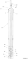
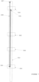
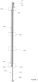
- FIGS 1 and 2 illustrate an umbrella 10 according to a first embodiment of the present invention in its open and closed positions (or configurations).
- the umbrella 10 has a central spine 12; a handle grip 14; a canopy framework comprising a plurality of support arms 16 and associated braces 18; a tensioning mechanism comprising a plurality of tensioning braces 20 and associated extension levers 22; a main canopy 24; a mini canopy 26; and an end cap 28.
- the umbrella 10 further comprises a first optional sleeve 30 to assist in retaining any water within the closed umbrella and a second optional sleeve 32 to assist in preventing water ingress into the central spine 12 and the internal mechanisms of the central spine 12 which will be described later.
- the illustrated umbrella 10 also has optional internal canopies 34, 36 which act to hide the canopy framework and tensioning mechanism when the umbrella 10 is in the open position.
- the central spine 12 is a typically tubular structure that supports the canopy framework, tensioning mechanism and the main canopy 24. In its lowest section the central spine 12 supports the handle grip 14. In its uppermost section the central spine 12 supports a string and pulley system which will be described later.
- the central spine 12 is telescopic and of variable length, however in the embodiment illustrated the length of the central spine is fixed, and is not telescopic.
- the handle grip 14 is fixed on to the lowest section of the central spine 12.
- the handle grip 14 is usually cylindrical and is usually made from plastic or wood.
- the handle grip 14 is hollow and configured to receive a portion of the canopy framework, tensioning mechanism and the main canopy 24 when the umbrella 10 is in the closed configuration as can be seen in Figure 1 . This helps to maintain the full length of the umbrella 10 in the closed position being consistent with traditional umbrellas.
- the handle grip 14 is solid is not configured to retain any portion of the portion of the canopy framework, tensioning mechanism or the main canopy 24 when the umbrella 10 is in the closed configuration.
- a sleeve cover (not shown) for the umbrella 10, is fixed onto the handle grip.
- the sleeve cover in one alternative is made out of a flexible material such as fabric which may be rolled up or down, in another alternative the sleeve cover is made out of tubing, in one alternative telescopic with one or more segments and in one alternative transparent to minimise the visual impact of the sleeve cover.
- the general principle of the umbrella 10 of the present invention is that the main canopy 24 has an inside face closest the canopy framework and an outside face remote from the canopy framework such that when the umbrella 10 is in the closed configuration the main canopy 24 is folded inside out such that the outside face of the main canopy 24, which is usually wet after use, is folded upon itself, substantially preventing water dripping from the main canopy 24 and allowing the user to handle the dry inside face of the main canopy 24.
- the canopy framework has a plurality of support arms 16 extending radially from the central spine 12.
- Each support arm 16 may in one alternative be a single strut or in an alternative comprise a series of pivotally linked struts in substantially linear end-to-end alignment.
- the strut located closest to the central spine 12 is called the main strut and is pivotally connected to a first sliding support 38 which is configured to slide vertically along the central spine 12. In the embodiment illustrated as any one strut is present this is the main strut.
- the inner end of the main strut is shaped so that the central axis of the main strut is offset from the pivot connection point on the first sliding support 38. This means that when the umbrella 10 and thus the canopy framework is in its closed position, the fact that the main strut is offset from the pivot connection point allows the main canopy 24 to fold within the space between the main strut and the central spine 12.
- the support arm 16 is further provided with a sliding strut 40 at the end of the series of struts, if provided, or main strut, which facilitates radial movement of the main canopy 24 for tensioning and for releasing the tension of the main canopy 24 about the canopy framework.
- the sliding strut 40 is configured to slide along and over the support arm 16 such that the total length of the support arm 16 can be increased when the sliding strut 40 extends over the end of the support arm 16 during the tensioning of the main canopy 24.
- the canopy framework is further provided with associated braces 18 which are pivotally connected to respective support arms 16 at one end and to a second sliding support 42 at their other end.
- the second sliding support 42 is also configured to slide vertically along the central spine 12.
- the tensioning mechanism has a plurality of tensioning braces 20 and associated extension levers 22 pivotally connected thereto extending radially from the central spine 12.
- Each of the tensioning braces 20 are pivotally connected at one end to a third sliding support (tensioning sliding support) 44 which is configured to slide vertically along the central spine 12.
- Each of the tensioning braces 20 are also pivotally connected to an associated extension lever 22 at their other end.
- the pivot connection point between the respective tensioning braces 20 and extension levers 22 are slidably connected by a sliding pivot 46 to their respective brace 18 of the canopy framework and are configured to be able to slide along the full length thereof.
- the end of the extension levers 22 that are not connected to the tensioning braces 20 are pivotally connected at point 48 to the respective sliding struts 40 of the canopy framework.
- the movement of the three sliding supports 38, 42, 44 about central spine 12 as discussed above is controlled by using a string and pulley system.
- the string is preferably kept under tension by using springs or in the alternative by using an elasticated material as will be discussed later in relation to Figures 6 to 10 .
- a fourth sliding support 50 As well as the three sliding supports 38, 42, 44 already discussed there is further provided a fourth sliding support 50.
- the first sliding support 38 supports the support arms 16 and the main canopy 24, the second sliding support 42 supports the braces 18 for the main canopy 24.
- the string and pulley system is arranged such that movement that reduces the gap between these first two sliding supports 38, 42 closes the canopy framework and thus the main canopy 24 and movement that increases the gap between these first two sliding supports 38, 42 opens the canopy framework and thus the main canopy 24.
- the third sliding support (tensioning sliding support) 44 actuates the tensioning mechanism.
- the fourth sliding support 50 actuates the movement between the first two sliding supports 38, 42 that facilitate the opening and closing of the main canopy 24.
- the actuation system comprises string and pulley system and the tensioning mechanism as described above.
- the three sliding supports 38, 42, 44 are provided with a latch and release arrangement 52 so that it is possible for them to either move together and are also capable of being released to move independently as required.
- Sleeve 32 is attached to the main canopy 24 near the first sliding support 38, and extends up to mini canopy 26.
- the outer surface of sleeve 32 is provided with a waterproof coating to allow for retention of the water located on the outside face of the main canopy 24 after used within the main canopy 24 and the sleeve 32 when the umbrella 10 is in the closed position.
- a portion of the sleeve 32 close to the mini canopy 26 and within the mini canopy 26 may be made from a water absorbing material to assist in water egress.
- the mini canopy 26 is provided with a second sleeve 30 which is configured to be extended over the folded main canopy 24 when the umbrella is in the closed position to provide further seal against the egress of water.
- the Inside of the sleeve 30 in one alternative is formed from or coated with a material configured to absorb water again to water egress.
- End cap 28 on the tip of the umbrella 10 is configured to support the mini canopy 26.
- the end cap 28 in one alternative is perforated 54 as illustrated to allow air circulation within the sleeve 32 and the mini canopy 26 to prevent the growth of mould or bacteria or the like.
- the central spine 12 in one alternative is a hollow cylinder which is open at both ends to further facilitate circulation of air. In a further alternative (not shown) the central spine is further perforated along its length.
- a stopper 56 is provided at the base of the central spine 12 which provides final stop closed position for the umbrella 10.
- a latch 58 and stopper 60 are provided at the top of the central spine 12 to allow the end cap 28 and the mini canopy 26 to move into a locked position when the main canopy 24 is open and lowered as necessary to provide a cover for the ends of the main canopy 24 and canopy framework when closed.
- four sliding supports 38, 42, 44, 50 are provided which are configured to slide along the outermost portion of the central spine 12; they actuate opening, closing and tensioning of the main canopy 24 and provide support when the umbrella is in the open position.
- Springs 62, 64 are provided and both act as a spacer between the sliding supports and also help initiate movement of the sliding supports.
- a narrow band of water absorbing fabric may also be attached to the inside face of the main canopy 24 as a further measure against water egress. This is because when the main canopy 24 is folded, there are a number of layers close to the tip of the umbrella and water may move between the layers.
- the main canopy marked 24 rotates from the closed position where the dry inside face of the canopy is on the outside and flips over so that the wet outside face is on the outside.
- the mini canopy 26 opens and stretches over the top of the main canopy 24.
- the fourth sliding support 50 which actuates the movement of the first sliding support 38 away from the second sliding support 42 comes to rest when the first sliding support 38 meets the stopper 60 and cannot move anymore.
- the third sliding support (tensioning sliding support) 44 continues to be pushed up, pushing the tensioning braces 20 which results in the sliding pivots 46 moving along braces 18, which in turn results in the extension of extension levers 22.
- extension levers 22 are pivotally connected to the sliding struts 40 at point 46 and the sliding struts 40 are configured to slide about the support arms 16.
- the sliding struts 40 are also, at their end furthest from the central spine 12, connected to the main canopy 24.
- This arrangement means that as the extension levers 22 are extended the sliding struts 40 slide along the support arms 16 away from the central spine 12 and in doing so pushes the main canopy 24 along the support arm 16 via the sliding struts 40, essentially changing the length of the support arm 16 which supports the main canopy 24.
- the third sliding support (tensioning sliding support) 44 locks in place which in turn locks the canopy framework in the open position.
- This locking mechanism in one alternative is provided by latch 52 upon which the third sliding support (tensioning sliding support) 44 rests.
- spring 64 is configured to couple the second and third sliding supports 42, 44 so that the tensioning is further assisted by braces 18.
- Latch 66 is the lower locking latch for the third sliding support (tensioning sliding support) 44 when the main canopy 24 is folded.
- Additional inner canopies 34, 36 may also be used as coverings for tension braces 20 and extension levers 22 to provide additional protection against water leakage or dampness. These additional internal canopies 34, 36 will also make handling of the canopy framework and tensioning mechanism safer because the frames would be behind the fabric of the inner canopies 34, 36.
- both canopies 34, 36 are provided separately in yet another alternative both canopies 34, 36 are provided as a single canopy.
- the internal canopies 34, 36 will also improve the performance of the umbrella 10 in the wind.
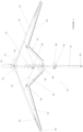
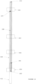
- FIG. 3 illustrates the tensioning mechanism in more detail.
- the tensioning mechanism includes the tensioning brace 20, sliding pivot 46 which moves along brace 18, and extension lever 22 for extending the sliding strut 40 which is arranged, in one alternative to telescopically to move along the support arm 16, effectively extending the length of the support arm 16 during the tensioning step to stretch out the main canopy 24.
- the extension lever 22 is pivotally connected to the sliding strut 40 at point 48.
- the main canopy 24 is also attached to sliding strut 40.
- the sliding struts 40 are tubular elements which fit around the full cross section of the support arms 16.
- the sliding struts 40 only fit around a portion of the full cross section of the support arms 16.
- corresponding grooves or channels and protrusions are provided in the sliding struts 40 and the support arms 16 to allow the sliding struts 40 to slide along the support arms 16.
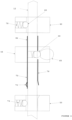
- Figure 4 illustrates the latch and release mechanisms in more detail which latch the first, second and third sliding supports 38, 42 and 44 and release them at the required stages of the process of opening or closing the umbrella 10.
- This allows the user to move just a single sliding support, which is the same as with conventional umbrellas.
- the single sliding support is moved by the user all the other movements of the other sliding supports relative to each other are achieved by latching or releasing the various sliding supports as required.
- the third sliding support 44 is the one that is moved by the user.
- the release button 68 is pressed. This allows the latch 66 to release the third sliding support 44.
- the canopy framework and thus the main canopy 24 rotates into the open position and stops when the first sliding support 38 comes to a rest position along the central spine 12, i.e. when the first sliding support 38 comes into contact with the latch 58 and stopper 60.
- the fourth sliding support 50 is unable to move upwards anymore and as such when the third sliding support 44 is moved further the wedge 72 of first spring arm 70 moves past latch 74 releasing the third sliding support 44 from the fourth sliding support 50.
- a second spring arm 76 which is connected to the third sliding support 44 passes through the fourth sliding support 50, releasing latch 52 located below it which allows the third and fourth sliding supports 44, 50 to lock together for movement down the central spine 12.
- the second sliding support 42 is moved up the central spine 12 as the first sliding support 38 moves upwards until latch 78 locks into aperture 80 on the central spine 12. This allows the third sliding support 44 to continue to move up the central spine 12 whilst the second sliding support 42 is temporarily held, which ensures the tensioning mechanism is mobilised.
- the third spring arm 82 attached to the third sliding support 44 passes through the second sliding support 42 releasing latch 78 so both the second and third sliding supports 42, 44 are able to move further until full tensioning of the main canopy 24 is achieved.
- FIG. 5 illustrates an additional feature that can be incorporated into the latch mechanisms illustrated in Figure 4 .
- a further latch and release mechanism is incorporated between the second and third sliding supports 142, 144.
- spring arm 182 which is attached to third sliding support 144 is also provided with a wedge 184.
- second sliding support 142 is close enough to third sliding support 144 such that wedge 184 is on the upper side of latch 178.
- this additional latch mechanism means that the second sliding support 142 is held back ensuring that the canopy framework and thus the main canopy 24 opens up.
- This opening of the canopy framework and thus the main canopy 24 can also be assisted by the use of springs 62, 64 as shown in Figures 1 and 2 .
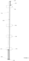
- Figure 6 illustrates a first alternative arrangement for the string pulley system with the sliding supports 238, 242, 244 and 250 shown as being uncoupled from each other and released from the latch system explained in relation to Figures 4 and 5 .
- the fourth sliding support 250 is the actuator for moving the first sliding support 238 upwards along the central spine 12 and away relative to the second sliding support 242 to open the umbrella 10.
- all four sliding supports 238, 242, 244, 250 are close together as illustrated in Figure 1 .
- the fourth sliding support 250 moves upwards along the central spine 212, because of the arrangement of the string and pulley system illustrated in Figure 6 the first sliding support 238 is moved twice the distance that is moved by the fourth sliding support 250.
- the string 288 is fixed at position 286 below the fourth sliding support 250 on the central spine 212.
- the string 288 then passes round a first pulley 290 which is attached to the fourth sliding support 250 and back down to pass around a second pulley 292 attached to the central spine 212.
- the string 288 then passes around a third pulley 294 which is attached to the central spine 212 close to the top thereof and finally fixed on to the first sliding support 238 at position 296.
- the fourth sliding support 250 with first pulley 290 moves, the distance between the first pulley 290 and fixing point 286 and the distance between the first pulley 290 and the second pulley 292 increases, and thus the length of string 288 in these regions also increases resulting in the length of string 288 available between the second pulley 292 and the third pulley 294 and thus the third pulley 294 and fixing point 296 to shorten by twice the amount of the movement of the fourth sliding support 250.
- Figure 7 illustrates an alternative arrangement of a string and pulley system.
- the sting and pulley system is arranged to bring the first sliding support 338 towards the second, third and fourth sliding supports 342, 344, 350.
- the sliding supports 338, 342, 344, 350 again are shown as being uncoupled.
- the string 388 is attached to the central spine 312 at point 387.
- the first pulley 389 is attached to the fourth sliding support 350.
- the string 388 is stretched from fixing point 387 around the first pulley 389 and then fixed at point 391 to first sliding support 338.
- This arrangement is for moving the first sliding support 338 down towards the rest of the sliding supports 342, 344, 350 and is achieved by pulling the first sliding support 338 down towards the hand grip to close the umbrella 10. This action for the user is again exactly the same as how conventional umbrellas are closed by the user.
- Figure 8 illustrates a further alternative arrangement string and pulley system which works using the same principle.
- the fourth sliding support 450 which actuates the motion of the first sliding support 438 has a sleeve 498 attached to it which extends as far as is required for opening and closing the umbrella 10.
- the string 485 arrangement for moving the first sliding support 438 close to the rest of the sliding supports 442, 444, 450 to result in the closing the umbrella 10 is exactly same as that illustrated in Figure 7 .
- the string 488 arrangement to open the umbrella 10 as shown in Figure 6 has been simplified by introducing a sleeve 498 attached to the actuating fourth sliding support 450 so that the pulley 489 attached to the fourth sliding support 450 can be placed remote from the first sliding support 438 at a distance that allows the first sliding support 438 to move to the height required to open the umbrella 10.
- This arrangement requires two less pulleys than the arrangement shown in Figure 6 .
- the two additional pulleys in Figure 6 are only required to change the direction of the string 388. In this alternative, this is achieved by the sleeve 498 instead.
- Figure 9 illustrates an alternative arrangement in which the central spine 512 and the sleeve 598, which is attached to the actuating fourth sliding support 550, are arranged telescopically.
- the string 588 is fixed on to the central spine 512 at point 586 and to the first sliding support at point 587.
- a first pulley 589 is attached at a position lower than fixing point 586 on to the fourth sliding support 550 and a second pulley 594 is attached on to the sleeve 598 at a distance remote from the first pulley 589 so that the first sliding support is able to have the full movement required to open and close the umbrella.
- the sleeve 598 is also provided with a slot 599 to allow the string to be fixed to the central spine 512.
- Figure 10 illustrates a further alternative arrangement which is similar to arrangement shown in Figure 9 but in this case there is no slot provided in sleeve 698.
- the string 688 that is attached to the central spine 612 at point 686 is positioned between the sleeve 698 and the central spine 612. With pulley 689 being located within the fourth sliding support 650 and the fourth sliding support being configured to accommodate the string 688 inside.
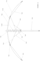
- Figure 11 illustrates an alternative arrangement of the tensioning elements first illustrated in Figure 2 .
- sliding pivot 746 is configure to slide along support arm 716 rather than tensioning brace 718.
- an optional extendible strut 7100 may be provided between sliding support 738 and sliding pivot 746. Extendible strut 7100 may be, for example, extensible, telescopic, elastic, sprung, or stretchable.
- an optional stopper 7101 may be provided to restrict or limit the movement of sliding pivot 746 about support arm 716. The canopy has not been shown in this Figure.
- the string may be proved with springs to assist in maintaining the required tension in the string.
- the string may be elasticated.
- the present aspect and embodiment represent currently the best ways to the application of putting the invention into practice.
- the four sliding supports are shown uncoupled as they each serve a function.
- the fourth sliding support closest to the handle grip actuates the movement of the first sliding support to facilitate the opening and closing of the canopy.
- the first sliding support supports the support arms that support the main canopy.
- the second sliding support supports the braces that brace the support arms that support the main canopy.
- the third sliding support actuates the tensioning mechanism of the main canopy.
- the tensioning mechanism is required because the motions of the main canopy form closed to open positions and then tensioning of the fabric once deployed, necessitates changes in the diameter of the main canopy. This mechanism illustrates one way how this is achieved.
- Figures 6 to 10 outlines way of achieving movement of the sliding supports without altering the way the user understands how an umbrella is opened or closed.
- Figures 4 and 5 illustrate how for both practicality and for ease of use the latch and release mechanism can be used to achieve coupling and decoupling of the three lower sliding supports to achieve this.
Landscapes
- Walking Sticks, Umbrellas, And Fans (AREA)
- Tents Or Canopies (AREA)
Applications Claiming Priority (2)
| Application Number | Priority Date | Filing Date | Title |
|---|---|---|---|
| GBGB1217411.6A GB201217411D0 (en) | 2012-09-28 | 2012-09-28 | Inside out umbrella |
| PCT/GB2013/052524 WO2014049367A1 (en) | 2012-09-28 | 2013-09-27 | Umbrella |
Publications (2)
| Publication Number | Publication Date |
|---|---|
| EP2900103A1 EP2900103A1 (en) | 2015-08-05 |
| EP2900103B1 true EP2900103B1 (en) | 2023-07-05 |
Family
ID=47225391
Family Applications (1)
| Application Number | Title | Priority Date | Filing Date |
|---|---|---|---|
| EP13774769.7A Active EP2900103B1 (en) | 2012-09-28 | 2013-09-27 | Umbrella |
Country Status (7)
| Country | Link |
|---|---|
| US (1) | US9993053B2 (enExample) |
| EP (1) | EP2900103B1 (enExample) |
| JP (1) | JP6246815B2 (enExample) |
| CN (1) | CN104812266B (enExample) |
| GB (2) | GB201217411D0 (enExample) |
| HK (1) | HK1212568A1 (enExample) |
| WO (1) | WO2014049367A1 (enExample) |
Families Citing this family (10)
| Publication number | Priority date | Publication date | Assignee | Title |
|---|---|---|---|---|
| TW201701798A (zh) * | 2015-05-19 | 2017-01-16 | Gb設計有限公司 | 可折疊傘 |
| DE102015219404B4 (de) | 2015-10-07 | 2017-10-19 | Erich Mayer | Schirm, insbesondere Standschirm |
| TWM532763U (en) * | 2016-03-04 | 2016-12-01 | ren-hao Dai | Rib structure of inverted umbrella |
| US9538819B1 (en) * | 2016-04-19 | 2017-01-10 | Candice Hayes | Umbrella having an expandable canopy |
| US9788617B1 (en) * | 2016-09-29 | 2017-10-17 | Xiamen Mingho Brothers Mfg Co., Ltd. | Pull rib of wind-resistant umbrella |
| CN106617557B (zh) * | 2017-01-19 | 2018-03-09 | 汪浩澜 | 一种易收容雨伞 |
| USD857372S1 (en) * | 2017-03-31 | 2019-08-27 | Kris Jan Simon Van Puyvelde | Umbrella |
| CN109463867A (zh) * | 2018-11-01 | 2019-03-15 | 浙江工业大学上虞研究院有限公司 | 一种断层折叠辅助功能用伞 |
| KR102053127B1 (ko) * | 2018-11-08 | 2019-12-06 | 한국기술교육대학교 산학협력단 | 그늘막 자동 개폐장치 |
| GB2593855B (en) * | 2020-01-02 | 2024-01-31 | Kazim Jenan | Inside out compact umbrella |
Citations (3)
| Publication number | Priority date | Publication date | Assignee | Title |
|---|---|---|---|---|
| JPS4892145A (enExample) * | 1972-03-06 | 1973-11-30 | ||
| US3837352A (en) * | 1972-07-08 | 1974-09-24 | Telesco Brophey Ltd | Umbrella |
| EP2477516A1 (en) * | 2009-09-18 | 2012-07-25 | Jenan Kazim | Umbrella folding upward and inside out |
Family Cites Families (44)
| Publication number | Priority date | Publication date | Assignee | Title |
|---|---|---|---|---|
| US952630A (en) * | 1908-10-03 | 1910-03-22 | Frederick D Philp | Umbrella. |
| US1073562A (en) * | 1913-03-25 | 1913-09-16 | John Mitchell Beaver | Folding umbrella. |
| US1067435A (en) * | 1913-04-26 | 1913-07-15 | James A Mcnamara | Umbrella. |
| US1969821A (en) * | 1931-08-29 | 1934-08-14 | Louis A Capaldo | Umbrella |
| US1969171A (en) * | 1933-08-18 | 1934-08-07 | S W Evans & Son | Umbrella construction |
| NL50395C (enExample) * | 1937-12-15 | |||
| US2296666A (en) * | 1939-06-15 | 1942-09-22 | Haupt Hans | Folding or collapsible umbrella |
| US3217724A (en) * | 1963-10-14 | 1965-11-16 | Szivatz Fedor | Umbrella of reducible length |
| US3732880A (en) * | 1969-07-25 | 1973-05-15 | Telesco Brophey Ltd | Umbrella |
| US3702618A (en) * | 1969-07-25 | 1972-11-14 | Telesco Brophey Ltd | Collapsible umbrella |
| JPS4828148B1 (enExample) * | 1970-04-21 | 1973-08-29 | ||
| GB1266264A (enExample) * | 1970-07-07 | 1972-03-08 | ||
| JPS511964Y2 (enExample) * | 1971-05-13 | 1976-01-21 | ||
| US4149553A (en) * | 1978-07-21 | 1979-04-17 | Lee Ying I | Opening and closing device for an umbrella |
| JPS56123117U (enExample) * | 1980-02-21 | 1981-09-19 | ||
| JPS6030203B2 (ja) * | 1981-09-11 | 1985-07-15 | 九和洋傘股ふん有限公司 | 子骨の自動開展装置を有する折畳み洋傘 |
| JPS5870119U (ja) * | 1981-11-04 | 1983-05-12 | 白田 寛 | パイプ骨製軽量傘 |
| JPS58163304A (ja) * | 1982-03-19 | 1983-09-28 | 木田 信敏 | 楕円型天蓋部を備えた傘 |
| JPH02203804A (ja) * | 1988-07-29 | 1990-08-13 | Fukuta Yosan Kosho Kofun Yugenkoshi | 傘骨 |
| DE8909209U1 (de) * | 1989-07-29 | 1990-11-29 | Aug. Grönlinger Nachf. GmbH & Co KG, 5600 Wuppertal | Schirm, insbesondere Regenschirm |
| JPH088882B2 (ja) * | 1990-07-06 | 1996-01-31 | 一郎 奥津 | 反転する洋傘 |
| DE19505707C1 (de) | 1995-02-20 | 1996-03-07 | Jochen Hoehfeld | Schirm |
| CN2228720Y (zh) * | 1995-05-09 | 1996-06-12 | 容广元 | 可用单手开关的直伞 |
| US6082383A (en) * | 1998-07-28 | 2000-07-04 | Wilson; Robert Joe | Umbrella with actuator sleeve for manual and automatic operation |
| EP1005804A1 (en) | 1998-12-03 | 2000-06-07 | Rafael Martinez Fernandez | Improved umbrella |
| GB9903285D0 (en) | 1999-02-12 | 1999-04-07 | Kazim Jenan | Self-sealing non drip,easy to store compact umbrella that rights itself when blown inside out in the wind |
| TW378507U (en) * | 1999-05-24 | 2000-01-01 | Asia Umbrella Ind Co Ltd | Structure for the umbrella of improved model |
| TW405351U (en) * | 1999-10-08 | 2000-09-11 | Jang Jen Man | Improvement of single stem umbrella extending structure |
| US6863081B2 (en) * | 2003-02-04 | 2005-03-08 | Hsieh Ming-Ju | Wind-proof umbrella rib structure |
| CN2701295Y (zh) * | 2003-04-28 | 2005-05-25 | 吴俌葆 | 反向雨伞 |
| US20050022459A1 (en) * | 2003-07-28 | 2005-02-03 | Chen-Maan Chang | Automatic straight umbrella |
| JP2006187374A (ja) * | 2004-12-30 | 2006-07-20 | Motoharu Furuno | 裏返しに閉じる雨傘 |
| US20060266396A1 (en) * | 2005-05-27 | 2006-11-30 | Perry George Jr | Windproof umbrella |
| US7484518B2 (en) * | 2006-01-23 | 2009-02-03 | Noah Brader | Reversible umbrella |
| CN201025938Y (zh) | 2007-05-16 | 2008-02-27 | 何达勤 | 折叠式滑杆遮阳伞 |
| KR100982792B1 (ko) * | 2008-08-04 | 2010-09-20 | 부일 이 | 우산 |
| JP2011005224A (ja) | 2008-10-02 | 2011-01-13 | U Trading Corporation:Kk | 逆閉じ用傘 |
| KR101195096B1 (ko) * | 2009-04-20 | 2012-10-29 | 노규영 | 슬라이드 방식의 접이식 우산 |
| KR101069825B1 (ko) * | 2009-09-08 | 2011-10-04 | 부일 이 | 우산살어셈블리 및 접이식 우산 |
| CN201571608U (zh) * | 2009-11-09 | 2010-09-08 | 亚达科技集团有限公司 | 遮阳伞 |
| KR101131203B1 (ko) * | 2010-03-11 | 2012-03-28 | 부일 이 | 양산 |
| US8240322B2 (en) * | 2010-07-06 | 2012-08-14 | Tzu-Cheng Chang | Splash-proof umbrella structure |
| TWM491361U (zh) * | 2013-10-04 | 2014-12-11 | Yau Wai Howard Chan | umbrella |
| US9538819B1 (en) * | 2016-04-19 | 2017-01-10 | Candice Hayes | Umbrella having an expandable canopy |
-
2012
- 2012-09-28 GB GBGB1217411.6A patent/GB201217411D0/en not_active Ceased
-
2013
- 2013-09-27 CN CN201380062236.1A patent/CN104812266B/zh active Active
- 2013-09-27 GB GB1317163.2A patent/GB2507649B/en not_active Expired - Fee Related
- 2013-09-27 EP EP13774769.7A patent/EP2900103B1/en active Active
- 2013-09-27 HK HK16100486.3A patent/HK1212568A1/zh unknown
- 2013-09-27 JP JP2015533694A patent/JP6246815B2/ja active Active
- 2013-09-27 WO PCT/GB2013/052524 patent/WO2014049367A1/en not_active Ceased
- 2013-09-27 US US14/431,468 patent/US9993053B2/en active Active
Patent Citations (3)
| Publication number | Priority date | Publication date | Assignee | Title |
|---|---|---|---|---|
| JPS4892145A (enExample) * | 1972-03-06 | 1973-11-30 | ||
| US3837352A (en) * | 1972-07-08 | 1974-09-24 | Telesco Brophey Ltd | Umbrella |
| EP2477516A1 (en) * | 2009-09-18 | 2012-07-25 | Jenan Kazim | Umbrella folding upward and inside out |
Also Published As
| Publication number | Publication date |
|---|---|
| HK1212568A1 (zh) | 2016-06-17 |
| WO2014049367A1 (en) | 2014-04-03 |
| GB2507649A (en) | 2014-05-07 |
| CN104812266A (zh) | 2015-07-29 |
| JP6246815B2 (ja) | 2017-12-13 |
| EP2900103A1 (en) | 2015-08-05 |
| GB2507649B (en) | 2015-06-03 |
| JP2015532132A (ja) | 2015-11-09 |
| GB201217411D0 (en) | 2012-11-14 |
| US9993053B2 (en) | 2018-06-12 |
| US20150265013A1 (en) | 2015-09-24 |
| CN104812266B (zh) | 2016-10-12 |
| GB201317163D0 (en) | 2013-11-06 |
Similar Documents
| Publication | Publication Date | Title |
|---|---|---|
| EP2900103B1 (en) | Umbrella | |
| US10716373B2 (en) | Foldable umbrella with dynamic rib structure | |
| JP2015532132A5 (enExample) | ||
| US8893736B2 (en) | Umbrella folding upward and inside out | |
| US20160113364A1 (en) | Cantilevered umbrella with rotation system | |
| JPS6134803B2 (enExample) | ||
| US20150351505A1 (en) | Cantilevered umbrella | |
| CN109123948A (zh) | 一种折叠框架 | |
| US11013303B2 (en) | Umbrella assembly set up devices | |
| CA2680424C (en) | Automatically-collapsible multi-folded umbrella | |
| KR101468013B1 (ko) | 돔형 텐트의 폴대구조 | |
| US3853135A (en) | Umbrella frame | |
| US9585447B1 (en) | Reversible umbrella | |
| KR200404998Y1 (ko) | 폭가변형 파라솔 | |
| KR102498235B1 (ko) | 우산 형상 구조체 | |
| CN209760949U (zh) | 一种带锁定的伞头 | |
| KR101084368B1 (ko) | 파라솔 | |
| US20110290289A1 (en) | Dual-crown umbrella | |
| CN109419116B (zh) | 伞 | |
| JP3170930U (ja) | 傘 | |
| KR200389733Y1 (ko) | 절첩식 쌍봉 파라솔 | |
| EP2159350A1 (en) | Collapsible shelter | |
| KR20250153090A (ko) | 접이식 파라솔 | |
| CN114929061A (zh) | 一种内翻外紧凑型伞 | |
| KR20100110529A (ko) | 복층형 파라솔 |
Legal Events
| Date | Code | Title | Description |
|---|---|---|---|
| PUAI | Public reference made under article 153(3) epc to a published international application that has entered the european phase |
Free format text: ORIGINAL CODE: 0009012 |
|
| 17P | Request for examination filed |
Effective date: 20150424 |
|
| AK | Designated contracting states |
Kind code of ref document: A1 Designated state(s): AL AT BE BG CH CY CZ DE DK EE ES FI FR GB GR HR HU IE IS IT LI LT LU LV MC MK MT NL NO PL PT RO RS SE SI SK SM TR |
|
| AX | Request for extension of the european patent |
Extension state: BA ME |
|
| DAX | Request for extension of the european patent (deleted) | ||
| REG | Reference to a national code |
Ref country code: HK Ref legal event code: DE Ref document number: 1212568 Country of ref document: HK |
|
| STAA | Information on the status of an ep patent application or granted ep patent |
Free format text: STATUS: EXAMINATION IS IN PROGRESS |
|
| 17Q | First examination report despatched |
Effective date: 20180319 |
|
| GRAP | Despatch of communication of intention to grant a patent |
Free format text: ORIGINAL CODE: EPIDOSNIGR1 |
|
| STAA | Information on the status of an ep patent application or granted ep patent |
Free format text: STATUS: GRANT OF PATENT IS INTENDED |
|
| INTG | Intention to grant announced |
Effective date: 20221109 |
|
| GRAJ | Information related to disapproval of communication of intention to grant by the applicant or resumption of examination proceedings by the epo deleted |
Free format text: ORIGINAL CODE: EPIDOSDIGR1 |
|
| STAA | Information on the status of an ep patent application or granted ep patent |
Free format text: STATUS: EXAMINATION IS IN PROGRESS |
|
| GRAP | Despatch of communication of intention to grant a patent |
Free format text: ORIGINAL CODE: EPIDOSNIGR1 |
|
| STAA | Information on the status of an ep patent application or granted ep patent |
Free format text: STATUS: GRANT OF PATENT IS INTENDED |
|
| INTC | Intention to grant announced (deleted) | ||
| INTG | Intention to grant announced |
Effective date: 20230413 |
|
| GRAS | Grant fee paid |
Free format text: ORIGINAL CODE: EPIDOSNIGR3 |
|
| GRAA | (expected) grant |
Free format text: ORIGINAL CODE: 0009210 |
|
| STAA | Information on the status of an ep patent application or granted ep patent |
Free format text: STATUS: THE PATENT HAS BEEN GRANTED |
|
| AK | Designated contracting states |
Kind code of ref document: B1 Designated state(s): AL AT BE BG CH CY CZ DE DK EE ES FI FR GB GR HR HU IE IS IT LI LT LU LV MC MK MT NL NO PL PT RO RS SE SI SK SM TR |
|
| REG | Reference to a national code |
Ref country code: CH Ref legal event code: EP |
|
| REG | Reference to a national code |
Ref country code: AT Ref legal event code: REF Ref document number: 1583992 Country of ref document: AT Kind code of ref document: T Effective date: 20230715 |
|
| REG | Reference to a national code |
Ref country code: DE Ref legal event code: R096 Ref document number: 602013084169 Country of ref document: DE |
|
| REG | Reference to a national code |
Ref country code: IE Ref legal event code: FG4D |
|
| P01 | Opt-out of the competence of the unified patent court (upc) registered |
Effective date: 20230706 |
|
| REG | Reference to a national code |
Ref country code: LT Ref legal event code: MG9D |
|
| REG | Reference to a national code |
Ref country code: NL Ref legal event code: MP Effective date: 20230705 |
|
| REG | Reference to a national code |
Ref country code: AT Ref legal event code: MK05 Ref document number: 1583992 Country of ref document: AT Kind code of ref document: T Effective date: 20230705 |
|
| PG25 | Lapsed in a contracting state [announced via postgrant information from national office to epo] |
Ref country code: NL Free format text: LAPSE BECAUSE OF FAILURE TO SUBMIT A TRANSLATION OF THE DESCRIPTION OR TO PAY THE FEE WITHIN THE PRESCRIBED TIME-LIMIT Effective date: 20230705 |
|
| PG25 | Lapsed in a contracting state [announced via postgrant information from national office to epo] |
Ref country code: GR Free format text: LAPSE BECAUSE OF FAILURE TO SUBMIT A TRANSLATION OF THE DESCRIPTION OR TO PAY THE FEE WITHIN THE PRESCRIBED TIME-LIMIT Effective date: 20231006 |
|
| PG25 | Lapsed in a contracting state [announced via postgrant information from national office to epo] |
Ref country code: ES Free format text: LAPSE BECAUSE OF FAILURE TO SUBMIT A TRANSLATION OF THE DESCRIPTION OR TO PAY THE FEE WITHIN THE PRESCRIBED TIME-LIMIT Effective date: 20230705 |
|
| PG25 | Lapsed in a contracting state [announced via postgrant information from national office to epo] |
Ref country code: IS Free format text: LAPSE BECAUSE OF FAILURE TO SUBMIT A TRANSLATION OF THE DESCRIPTION OR TO PAY THE FEE WITHIN THE PRESCRIBED TIME-LIMIT Effective date: 20231105 |
|
| PG25 | Lapsed in a contracting state [announced via postgrant information from national office to epo] |
Ref country code: SE Free format text: LAPSE BECAUSE OF FAILURE TO SUBMIT A TRANSLATION OF THE DESCRIPTION OR TO PAY THE FEE WITHIN THE PRESCRIBED TIME-LIMIT Effective date: 20230705 Ref country code: RS Free format text: LAPSE BECAUSE OF FAILURE TO SUBMIT A TRANSLATION OF THE DESCRIPTION OR TO PAY THE FEE WITHIN THE PRESCRIBED TIME-LIMIT Effective date: 20230705 Ref country code: PT Free format text: LAPSE BECAUSE OF FAILURE TO SUBMIT A TRANSLATION OF THE DESCRIPTION OR TO PAY THE FEE WITHIN THE PRESCRIBED TIME-LIMIT Effective date: 20231106 Ref country code: NO Free format text: LAPSE BECAUSE OF FAILURE TO SUBMIT A TRANSLATION OF THE DESCRIPTION OR TO PAY THE FEE WITHIN THE PRESCRIBED TIME-LIMIT Effective date: 20231005 Ref country code: LV Free format text: LAPSE BECAUSE OF FAILURE TO SUBMIT A TRANSLATION OF THE DESCRIPTION OR TO PAY THE FEE WITHIN THE PRESCRIBED TIME-LIMIT Effective date: 20230705 Ref country code: LT Free format text: LAPSE BECAUSE OF FAILURE TO SUBMIT A TRANSLATION OF THE DESCRIPTION OR TO PAY THE FEE WITHIN THE PRESCRIBED TIME-LIMIT Effective date: 20230705 Ref country code: IS Free format text: LAPSE BECAUSE OF FAILURE TO SUBMIT A TRANSLATION OF THE DESCRIPTION OR TO PAY THE FEE WITHIN THE PRESCRIBED TIME-LIMIT Effective date: 20231105 Ref country code: HR Free format text: LAPSE BECAUSE OF FAILURE TO SUBMIT A TRANSLATION OF THE DESCRIPTION OR TO PAY THE FEE WITHIN THE PRESCRIBED TIME-LIMIT Effective date: 20230705 Ref country code: GR Free format text: LAPSE BECAUSE OF FAILURE TO SUBMIT A TRANSLATION OF THE DESCRIPTION OR TO PAY THE FEE WITHIN THE PRESCRIBED TIME-LIMIT Effective date: 20231006 Ref country code: FI Free format text: LAPSE BECAUSE OF FAILURE TO SUBMIT A TRANSLATION OF THE DESCRIPTION OR TO PAY THE FEE WITHIN THE PRESCRIBED TIME-LIMIT Effective date: 20230705 Ref country code: ES Free format text: LAPSE BECAUSE OF FAILURE TO SUBMIT A TRANSLATION OF THE DESCRIPTION OR TO PAY THE FEE WITHIN THE PRESCRIBED TIME-LIMIT Effective date: 20230705 Ref country code: AT Free format text: LAPSE BECAUSE OF FAILURE TO SUBMIT A TRANSLATION OF THE DESCRIPTION OR TO PAY THE FEE WITHIN THE PRESCRIBED TIME-LIMIT Effective date: 20230705 |
|
| PG25 | Lapsed in a contracting state [announced via postgrant information from national office to epo] |
Ref country code: PL Free format text: LAPSE BECAUSE OF FAILURE TO SUBMIT A TRANSLATION OF THE DESCRIPTION OR TO PAY THE FEE WITHIN THE PRESCRIBED TIME-LIMIT Effective date: 20230705 |
|
| REG | Reference to a national code |
Ref country code: DE Ref legal event code: R097 Ref document number: 602013084169 Country of ref document: DE |
|
| PG25 | Lapsed in a contracting state [announced via postgrant information from national office to epo] |
Ref country code: SM Free format text: LAPSE BECAUSE OF FAILURE TO SUBMIT A TRANSLATION OF THE DESCRIPTION OR TO PAY THE FEE WITHIN THE PRESCRIBED TIME-LIMIT Effective date: 20230705 Ref country code: RO Free format text: LAPSE BECAUSE OF FAILURE TO SUBMIT A TRANSLATION OF THE DESCRIPTION OR TO PAY THE FEE WITHIN THE PRESCRIBED TIME-LIMIT Effective date: 20230705 Ref country code: EE Free format text: LAPSE BECAUSE OF FAILURE TO SUBMIT A TRANSLATION OF THE DESCRIPTION OR TO PAY THE FEE WITHIN THE PRESCRIBED TIME-LIMIT Effective date: 20230705 Ref country code: DK Free format text: LAPSE BECAUSE OF FAILURE TO SUBMIT A TRANSLATION OF THE DESCRIPTION OR TO PAY THE FEE WITHIN THE PRESCRIBED TIME-LIMIT Effective date: 20230705 Ref country code: CZ Free format text: LAPSE BECAUSE OF FAILURE TO SUBMIT A TRANSLATION OF THE DESCRIPTION OR TO PAY THE FEE WITHIN THE PRESCRIBED TIME-LIMIT Effective date: 20230705 Ref country code: SK Free format text: LAPSE BECAUSE OF FAILURE TO SUBMIT A TRANSLATION OF THE DESCRIPTION OR TO PAY THE FEE WITHIN THE PRESCRIBED TIME-LIMIT Effective date: 20230705 |
|
| REG | Reference to a national code |
Ref country code: CH Ref legal event code: PL |
|
| PLBE | No opposition filed within time limit |
Free format text: ORIGINAL CODE: 0009261 |
|
| STAA | Information on the status of an ep patent application or granted ep patent |
Free format text: STATUS: NO OPPOSITION FILED WITHIN TIME LIMIT |
|
| PG25 | Lapsed in a contracting state [announced via postgrant information from national office to epo] |
Ref country code: LU Free format text: LAPSE BECAUSE OF NON-PAYMENT OF DUE FEES Effective date: 20230927 |
|
| REG | Reference to a national code |
Ref country code: BE Ref legal event code: MM Effective date: 20230930 |
|
| PG25 | Lapsed in a contracting state [announced via postgrant information from national office to epo] |
Ref country code: LU Free format text: LAPSE BECAUSE OF NON-PAYMENT OF DUE FEES Effective date: 20230927 Ref country code: IT Free format text: LAPSE BECAUSE OF FAILURE TO SUBMIT A TRANSLATION OF THE DESCRIPTION OR TO PAY THE FEE WITHIN THE PRESCRIBED TIME-LIMIT Effective date: 20230705 Ref country code: MC Free format text: LAPSE BECAUSE OF FAILURE TO SUBMIT A TRANSLATION OF THE DESCRIPTION OR TO PAY THE FEE WITHIN THE PRESCRIBED TIME-LIMIT Effective date: 20230705 |
|
| 26N | No opposition filed |
Effective date: 20240408 |
|
| REG | Reference to a national code |
Ref country code: IE Ref legal event code: MM4A |
|
| PG25 | Lapsed in a contracting state [announced via postgrant information from national office to epo] |
Ref country code: IE Free format text: LAPSE BECAUSE OF NON-PAYMENT OF DUE FEES Effective date: 20230927 |
|
| PG25 | Lapsed in a contracting state [announced via postgrant information from national office to epo] |
Ref country code: CH Free format text: LAPSE BECAUSE OF NON-PAYMENT OF DUE FEES Effective date: 20230930 |
|
| PG25 | Lapsed in a contracting state [announced via postgrant information from national office to epo] |
Ref country code: IE Free format text: LAPSE BECAUSE OF NON-PAYMENT OF DUE FEES Effective date: 20230927 Ref country code: CH Free format text: LAPSE BECAUSE OF NON-PAYMENT OF DUE FEES Effective date: 20230930 Ref country code: SI Free format text: LAPSE BECAUSE OF FAILURE TO SUBMIT A TRANSLATION OF THE DESCRIPTION OR TO PAY THE FEE WITHIN THE PRESCRIBED TIME-LIMIT Effective date: 20230705 |
|
| PG25 | Lapsed in a contracting state [announced via postgrant information from national office to epo] |
Ref country code: BE Free format text: LAPSE BECAUSE OF NON-PAYMENT OF DUE FEES Effective date: 20230930 |
|
| PG25 | Lapsed in a contracting state [announced via postgrant information from national office to epo] |
Ref country code: BG Free format text: LAPSE BECAUSE OF FAILURE TO SUBMIT A TRANSLATION OF THE DESCRIPTION OR TO PAY THE FEE WITHIN THE PRESCRIBED TIME-LIMIT Effective date: 20230705 |
|
| PG25 | Lapsed in a contracting state [announced via postgrant information from national office to epo] |
Ref country code: BG Free format text: LAPSE BECAUSE OF FAILURE TO SUBMIT A TRANSLATION OF THE DESCRIPTION OR TO PAY THE FEE WITHIN THE PRESCRIBED TIME-LIMIT Effective date: 20230705 |
|
| REG | Reference to a national code |
Ref country code: HK Ref legal event code: WD Ref document number: 1212568 Country of ref document: HK |
|
| PG25 | Lapsed in a contracting state [announced via postgrant information from national office to epo] |
Ref country code: CY Free format text: LAPSE BECAUSE OF FAILURE TO SUBMIT A TRANSLATION OF THE DESCRIPTION OR TO PAY THE FEE WITHIN THE PRESCRIBED TIME-LIMIT; INVALID AB INITIO Effective date: 20130927 |
|
| PG25 | Lapsed in a contracting state [announced via postgrant information from national office to epo] |
Ref country code: HU Free format text: LAPSE BECAUSE OF FAILURE TO SUBMIT A TRANSLATION OF THE DESCRIPTION OR TO PAY THE FEE WITHIN THE PRESCRIBED TIME-LIMIT; INVALID AB INITIO Effective date: 20130927 |
|
| PGFP | Annual fee paid to national office [announced via postgrant information from national office to epo] |
Ref country code: DE Payment date: 20250929 Year of fee payment: 13 |
|
| PGFP | Annual fee paid to national office [announced via postgrant information from national office to epo] |
Ref country code: GB Payment date: 20250918 Year of fee payment: 13 |
|
| PGFP | Annual fee paid to national office [announced via postgrant information from national office to epo] |
Ref country code: FR Payment date: 20250919 Year of fee payment: 13 |
|
| PG25 | Lapsed in a contracting state [announced via postgrant information from national office to epo] |
Ref country code: TR Free format text: LAPSE BECAUSE OF FAILURE TO SUBMIT A TRANSLATION OF THE DESCRIPTION OR TO PAY THE FEE WITHIN THE PRESCRIBED TIME-LIMIT Effective date: 20230705 |