EP2899705B1 - Laser scan sensor - Google Patents
Laser scan sensor Download PDFInfo
- Publication number
- EP2899705B1 EP2899705B1 EP13838772.5A EP13838772A EP2899705B1 EP 2899705 B1 EP2899705 B1 EP 2899705B1 EP 13838772 A EP13838772 A EP 13838772A EP 2899705 B1 EP2899705 B1 EP 2899705B1
- Authority
- EP
- European Patent Office
- Prior art keywords
- distance
- distance information
- unit
- measurement
- laser
- Prior art date
- Legal status (The legal status is an assumption and is not a legal conclusion. Google has not performed a legal analysis and makes no representation as to the accuracy of the status listed.)
- Active
Links
- 238000005259 measurement Methods 0.000 claims description 102
- 238000001514 detection method Methods 0.000 claims description 45
- 238000000034 method Methods 0.000 claims description 31
- 239000000284 extract Substances 0.000 claims description 4
- 230000000737 periodic effect Effects 0.000 claims description 4
- 230000000295 complement effect Effects 0.000 description 7
- 238000009434 installation Methods 0.000 description 6
- 230000000694 effects Effects 0.000 description 5
- 230000037237 body shape Effects 0.000 description 4
- 238000012937 correction Methods 0.000 description 4
- 238000010586 diagram Methods 0.000 description 4
- 238000007796 conventional method Methods 0.000 description 3
- 238000004364 calculation method Methods 0.000 description 2
- 238000012544 monitoring process Methods 0.000 description 2
- 230000002547 anomalous effect Effects 0.000 description 1
- 230000007423 decrease Effects 0.000 description 1
- 238000011161 development Methods 0.000 description 1
- 238000013213 extrapolation Methods 0.000 description 1
- 230000003287 optical effect Effects 0.000 description 1
- 239000004065 semiconductor Substances 0.000 description 1
Images


Classifications
-
- G—PHYSICS
- G01—MEASURING; TESTING
- G01S—RADIO DIRECTION-FINDING; RADIO NAVIGATION; DETERMINING DISTANCE OR VELOCITY BY USE OF RADIO WAVES; LOCATING OR PRESENCE-DETECTING BY USE OF THE REFLECTION OR RERADIATION OF RADIO WAVES; ANALOGOUS ARRANGEMENTS USING OTHER WAVES
- G01S17/00—Systems using the reflection or reradiation of electromagnetic waves other than radio waves, e.g. lidar systems
- G01S17/02—Systems using the reflection of electromagnetic waves other than radio waves
- G01S17/50—Systems of measurement based on relative movement of target
-
- G—PHYSICS
- G01—MEASURING; TESTING
- G01S—RADIO DIRECTION-FINDING; RADIO NAVIGATION; DETERMINING DISTANCE OR VELOCITY BY USE OF RADIO WAVES; LOCATING OR PRESENCE-DETECTING BY USE OF THE REFLECTION OR RERADIATION OF RADIO WAVES; ANALOGOUS ARRANGEMENTS USING OTHER WAVES
- G01S17/00—Systems using the reflection or reradiation of electromagnetic waves other than radio waves, e.g. lidar systems
- G01S17/02—Systems using the reflection of electromagnetic waves other than radio waves
- G01S17/04—Systems determining the presence of a target
-
- G—PHYSICS
- G01—MEASURING; TESTING
- G01S—RADIO DIRECTION-FINDING; RADIO NAVIGATION; DETERMINING DISTANCE OR VELOCITY BY USE OF RADIO WAVES; LOCATING OR PRESENCE-DETECTING BY USE OF THE REFLECTION OR RERADIATION OF RADIO WAVES; ANALOGOUS ARRANGEMENTS USING OTHER WAVES
- G01S17/00—Systems using the reflection or reradiation of electromagnetic waves other than radio waves, e.g. lidar systems
- G01S17/02—Systems using the reflection of electromagnetic waves other than radio waves
- G01S17/06—Systems determining position data of a target
- G01S17/42—Simultaneous measurement of distance and other co-ordinates
-
- G—PHYSICS
- G01—MEASURING; TESTING
- G01S—RADIO DIRECTION-FINDING; RADIO NAVIGATION; DETERMINING DISTANCE OR VELOCITY BY USE OF RADIO WAVES; LOCATING OR PRESENCE-DETECTING BY USE OF THE REFLECTION OR RERADIATION OF RADIO WAVES; ANALOGOUS ARRANGEMENTS USING OTHER WAVES
- G01S7/00—Details of systems according to groups G01S13/00, G01S15/00, G01S17/00
- G01S7/48—Details of systems according to groups G01S13/00, G01S15/00, G01S17/00 of systems according to group G01S17/00
- G01S7/4802—Details of systems according to groups G01S13/00, G01S15/00, G01S17/00 of systems according to group G01S17/00 using analysis of echo signal for target characterisation; Target signature; Target cross-section
-
- G—PHYSICS
- G01—MEASURING; TESTING
- G01S—RADIO DIRECTION-FINDING; RADIO NAVIGATION; DETERMINING DISTANCE OR VELOCITY BY USE OF RADIO WAVES; LOCATING OR PRESENCE-DETECTING BY USE OF THE REFLECTION OR RERADIATION OF RADIO WAVES; ANALOGOUS ARRANGEMENTS USING OTHER WAVES
- G01S7/00—Details of systems according to groups G01S13/00, G01S15/00, G01S17/00
- G01S7/48—Details of systems according to groups G01S13/00, G01S15/00, G01S17/00 of systems according to group G01S17/00
- G01S7/4808—Evaluating distance, position or velocity data
-
- G—PHYSICS
- G01—MEASURING; TESTING
- G01S—RADIO DIRECTION-FINDING; RADIO NAVIGATION; DETERMINING DISTANCE OR VELOCITY BY USE OF RADIO WAVES; LOCATING OR PRESENCE-DETECTING BY USE OF THE REFLECTION OR RERADIATION OF RADIO WAVES; ANALOGOUS ARRANGEMENTS USING OTHER WAVES
- G01S7/00—Details of systems according to groups G01S13/00, G01S15/00, G01S17/00
- G01S7/48—Details of systems according to groups G01S13/00, G01S15/00, G01S17/00 of systems according to group G01S17/00
- G01S7/481—Constructional features, e.g. arrangements of optical elements
- G01S7/4817—Constructional features, e.g. arrangements of optical elements relating to scanning
-
- G—PHYSICS
- G08—SIGNALLING
- G08B—SIGNALLING OR CALLING SYSTEMS; ORDER TELEGRAPHS; ALARM SYSTEMS
- G08B13/00—Burglar, theft or intruder alarms
- G08B13/18—Actuation by interference with heat, light, or radiation of shorter wavelength; Actuation by intruding sources of heat, light, or radiation of shorter wavelength
- G08B13/181—Actuation by interference with heat, light, or radiation of shorter wavelength; Actuation by intruding sources of heat, light, or radiation of shorter wavelength using active radiation detection systems
- G08B13/187—Actuation by interference with heat, light, or radiation of shorter wavelength; Actuation by intruding sources of heat, light, or radiation of shorter wavelength using active radiation detection systems by interference of a radiation field
Definitions
- the present invention relates to a laser scanning sensor which detects an intruder or the like into building premises, and particularly relates to a laser scanning sensor which can maintain its reliability in detection of an intruder or the like even in bad weather such as thick fog, heavy rain, and heavy snow.
- microwave sensor which emits microwaves to a detection area. If an intruder is present in the detection area, this microwave sensor catches a microwave reflected by the intruder and thereby detects the presence of the intruder.
- This "security system” is equipped with a sensor unit, a swivel camera unit, and a control unit.
- the sensor unit sets a monitoring area according to a scan angle for effecting two-dimensional scanning by a beam from the light distance meter.
- the sensor unit outputs distance data and angle data with regard to the intruder.
- the swivel camera unit is mounted on an electric swivel base, and swivels in conjunction with the sensor unit.
- the control unit checks the presence or absence of an intruder, calculates a position of the intruder based on the changed distance data and the changed angle data sent from the sensor unit, causes the swivel camera unit on the electric swivel base to swivel in accordance with the positional data, and causes a monitor to display image data of the intruder.
- a detection range covers a walking area for guiding pedestrians and a perimeter area around the walking area.
- An area sensor projects a pulse laser beam by a laser sensor to scan the detection range, and measures a reflection time of the beam. For each scanning point, the area sensor obtains a difference between a reflection time in the presence of an object and a reflection time in the absence of an object, and thereby calculates the shape and size of the object, and a vector related to the change in the object position for each scanning cycle. Based on the arithmetic signal, the area sensor distinguishes between an object moving along the walking area and an object moving across the walking area.
- Patent Literature 4 discloses a laser range finder, wherein, in order to prevent erroneous detection, a data correcting portion analysis the measured distance data and determines if reflection has occurred by identifying objects detected at anomalous short distances.
- This laser area sensor is characterized in having a first laser distance meter, a scanning mechanism unit, an information acquisition unit, a first information correction unit, a human body judgment unit, and a human body detection signal output unit.
- the first laser distance meter emits a pulse laser beam, measures the time from the emission until a beam is reflected by at least one object in the direction of the beam, and thereby obtains distance information to the object and received light level information of the reflected light.
- the scanning mechanism unit changes the measurement direction by the first laser distance meter. By allowing the scanning mechanism unit to change the measurement direction and allowing the first laser distance meter to make a periodic measurement, the information acquisition unit defines a detection area and sequentially acquires distance information and received light level information for each measurement direction.
- the distance information and the received light level information acquired by the information acquisition unit at a measurement cycle are compared, in each measurement direction, with the distance information and the received light level information acquired before and after this measurement cycle. If the comparison reveals a discontinuous change that exceeds a predetermined degree, the first information correction unit cancels the distance information that corresponds to the discontinuous change in this measurement cycle in the relevant measurement direction, and corrects a portion of received light level information that does not correspond to the discontinuous change.
- the human body judgment unit extracts a portion of distance information that has been corrected by the first information correction unit and that is assumed to be a human body. Based on the sequential movement status of the extracted portion of information, the human body judgment unit judges whether the extracted portion of information corresponds to a human body. If the human body judgment unit confirms the presence of a human body, the human body detection signal output unit outputs a human body detection signal.
- the laser area sensor as disclosed in Patent Literature 3 above is sufficiently capable of recognizing the shape of a human body.
- a laser beam in some measurement direction may completely reflect off a small droplet in the air.
- the distance information that corresponds to the human body shape may be partially unavailable.
- Such a lack of the distance information cannot be necessarily compensated by a simple noise-canceling process by a filter or the like, and may hamper recognition of the human body shape.
- An object of embodiments of the present invention is to provide a laser scanning sensor which can maximally eliminate or restore a negative effect on a laser beam in outdoor installation in bad weather or the like and which can improve the accuracy in detecting an intruder or the like in thick fog, heavy rain, heavy snow, etc., in comparison with the conventional techniques.
- a sensor includes a laser distance meter, a scanning mechanism unit, a distance information acquisition unit, a distance information interpolation unit, a judgment unit, and an alarm signal output unit.
- the laser distance meter emits a laser beam, and measures a distance to at least one object present in a direction of the laser beam, based on a time until the laser beam reflects off the at least one object and returns to the laser distance meter.
- the scanning mechanism unit changes a measurement direction by the laser distance meter.
- the distance information acquisition unit defines a detection area and sequentially acquires distance information containing at least one distance measured in each measurement direction in the detection area, by allowing the scanning mechanism unit to change the measurement direction and allowing the laser distance meter to make a periodic measurement.
- the distance information interpolation unit carries out an interpolation process for each measurement direction. The interpolation process is effected when a piece of the distance information acquired by the distance information acquisition unit is judged to correspond to an unintended object that exists at a shorter distance than an object to be originally detected, and when complementation of a piece of the distance information corresponding to the unintended object is judged to be possible based on a piece of the distance information acquired in an adjacent measurement direction or a piece of the distance information acquired at a previous measurement cycle.
- the interpolation process includes replacing the piece of the distance information in the measurement direction corresponding to the unintended object with an interpolated value based on the piece of the distance information acquired in the adjacent measurement direction at a same measurement cycle or with an interpolated value based on the piece of the distance information acquired in the measurement direction at the previous measurement cycle.
- the judgment unit extracts a portion of the distance information that may correspond to an object or a human body, wherein the distance information has been acquired by the distance information acquisition unit and has been subjected to the interpolation process by the distance information interpolation unit as required. Then, the judgment unit judges whether the extracted portion of the distance information corresponds to an object or a human body, based on a sequential movement status regarding the extracted portion of the distance information.
- the alarm signal output unit outputs an alarm signal if the judgment unit confirms presence of an object or a human body.
- This laser scanning sensor may also include a detection area information storage unit which stores, as detection area information, a maximum detectable distance, or a distance corresponding to an outer periphery of the detection area in each measurement direction. Further, the distance information interpolation unit may make a judgment that a piece of the distance information corresponds to the unintended object that exists at a shorter distance than the object to be originally detected, if a distance difference between the detection area information and a maximum distance contained in the distance information acquired in each measurement direction by the distance information acquisition unit is equal to or greater than a predetermined value.
- the distance information interpolation unit may make a judgment that the complementation is possible, with a proviso: that, in one or more measurement directions other than the measurement direction, a distance difference between the detection area information and a maximum distance contained in the distance information acquired at the same measurement cycle in each of the one or more other measurement directions is equal to or greater than the predetermined value; that the distance difference equal to or greater than the predetermined value is within a predetermined distance difference range; and that a total spacing of the one or more measurement directions whose distance information has been judged to correspond to the unintended object at a shorter distance than the object to be originally detected is narrower than the object to be originally detected.
- the laser scanning sensor having the above configurations accurately judges one or more measurement directions in which the distance information corresponding to a human body shape is partly unavailable because a laser beam has been completely reflected by a small droplet in the air due to thick fog, heavy rain, heavy snow, etc. Then, for each of the one or more measurement direction corresponding to the unintended object, the laser scanning sensor substitutes a complementary value based on pieces of the distance information acquired in the adjacent measurement directions on both sides or with a complementary value based on a piece of the distance information acquired at a previous measurement cycle in the measurement direction corresponding to the unintended object.
- the laser scanning sensor can maximally eliminate or restore a negative effect on a laser beam in outdoor installation in bad weather or the like, and can improve the accuracy in detecting an intruder or the like in thick fog, heavy rain, heavy snow, etc., in comparison with the conventional techniques.
- the laser scanning sensor according to the present invention can maximally eliminate or restore a negative effect on a laser beam in outdoor installation in bad weather or the like, and can improve the accuracy in detecting an intruder or the like in thick fog, heavy rain, heavy snow, etc., in comparison with the conventional techniques.
- FIG. 1 is a block diagram showing a schematic configuration of a laser scanning sensor 100 according to an embodiment of the present invention.
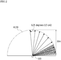
- FIG. 2 is a schematic plan view showing a detection area defined by the laser scanning sensor 100. In FIG. 2 , intervals between adjacent distance measurement directions are shown on a far greater scale than in reality, which is merely for the purpose of illustration.
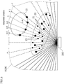
- FIG. 3 is a schematic diagram illustrating the measurement directions in which a complementing process of the distance data is carried out in the laser scanning sensor 100 in the event of heavy rain or the like.
- the laser scanning sensor 100 includes a laser distance meter 110, a scanning mechanism 120, a distance data acquisition unit 130, a distance data complementation unit 135, a human body judgment unit 140, an alarm output control unit 150, and a memory 160.
- the laser distance meter 110 obtains distance data by emitting a pulse laser beam in a certain direction and precisely measuring a fractional time until a beam reflects off at least one object in this direction and returns to the laser distance meter 110. Thereby, the laser distance meter 110 accurately measures the distance to each object and obtains distance data including a distance value for each object.
- the laser distance meter 110 may obtain three or more distance values in some measurement direction, it is supposed that the laser distance meter 110 obtains a maximum of two distance values from the short distance side (hereinafter called "first distance value d1" and “second distance value d2" from the short distance side) in this embodiment. It goes without saying that this configuration should not be taken as a limitation.
- a light-emitting element for the laser beam may be, for example, a semiconductor laser diode (LD).
- a light-receiving element may be, for example, an avalanche photodiode (APD).
- a light-receiving element may be, for example, an avalanche photodiode (APD).
- APD avalanche photodiode
- the laser distance meter is characterized by its ability to make a precise measurement up to a rather long distance, for example, to a maximum of several tens of meters, or even much longer depending on the situation. In this embodiment, the maximum detection range of the laser distance meter 110 is set to 30 meters.
- the scanning mechanism 120 is configured to rotate by means of a built-in motor (not shown) or the like.
- the scanning mechanism 120 is mechanically connected with at least a part of the laser distance meter 110 so as to change the distance measurement direction (angle) by the laser distance meter 110.
- the laser distance meter 110 may be allowed to rotate only at an optical system thereof or to rotate as a whole, or may adopt another configuration.
- the scanning mechanism 120 rotates in a predetermined direction at a constant speed, the distance measurement direction by the laser distance meter 110 changes in conjunction with this rotation.
- the distance data acquisition unit 130 defines a detection area A100 as shown in FIG. 2 , and sequentially acquires distance data at a predetermined time interval in each measurement direction (which may be also called “step") which are set at a predetermined angular interval within the detection area A100.
- distance data obtained in each measurement direction corresponds to the outer periphery (boundary) of the detection area A100.
- the distance data in this condition is stored in the memory 160 as reference distance data.
- the "distance data" is supposed to include, for example, following patterns.
- the reflected beam returns from the outer periphery of the detection area A100, and gives only the first distance value d1 which corresponds to the outer periphery. If no or hardly any beam is reflected back, which may happen in some situation, the maximum detectable range of the laser distance meter 110 may be assigned instead.
- the beam reflected by the human body 10 or the like gives an effective first distance value d1.
- the pulse laser beam is completely reflected by a droplet 21 in the air, and gives a first distance value d1 which corresponds to the droplet 21 instead of the human body 10.
- a droplet 21 in fog 20 or the like floats very close to the laser scanning sensor 100 and an apparent angle of the outer diameter of the droplet 21 is relatively great.
- the resulting first distance value d1 is assumed to be very small.
- this situation can be identified by whether the distance difference ⁇ d is equal to or greater than a predetermined value.
- the pulse laser beam is partially reflected by a droplet 21 floating forwardly of the human body 10 (nearer the laser scanning sensor 100), and gives an effective first distance value d1 in accordance with this reflected beam.
- the rest of the pulse laser beam that has not been reflected by the droplet 21 and has penetrated therethrough is reflected by the human body 10 or the like, and gives an effective distance value d2 in accordance with this reflected beam.
- two distance values are obtained in this measurement direction.
- the second distance value d2 is assumed to be quite larger than the first distance value d1 which corresponds to the nearer droplet 21, whereas the distance difference ⁇ d between the second distance value d2 and the distance to the outer periphery of the detection area A100 is small.
- this situation can be identified by whether the distance difference ⁇ d is smaller than a predetermined value.
- the second distance value d2 is assumed to be very small, and the distance difference ⁇ d between the second distance value d2 and the outer periphery the detection area A100 is small. This situation can be identified by whether the distance difference ⁇ d is equal to or greater than the predetermined value.
- the scanning cycle T may be set, for example, 50 ms (20 scans per second), and the pulse laser beams may be emitted in the range of a half rotation, i.e. 180 degrees, with a pulse width of 34 ns at an emission cycle of 34.7 ⁇ s.
- the thus set scanning mechanism 120 can make 720 measurements in the range of 180 degrees.
- the angular interval for the distance measurement is 0.25 degree, which is as little as an interval of about 13 cm even 30 meters away as shown in FIG. 2 , ensuring a considerably high spatial resolution in the detection area A100. Therefore, based on the distance data acquired by the distance data acquisition unit 130, it is possible to identify the position, size (width), shape, etc.
- the distance data can be acquired at each scanning cycle T, namely, at every 50 ms. It should be understood that the numerical values given herein are mere examples.
- the distance data complementation unit 135 analyzes distance data and the like acquired by the distance data acquisition unit 130. If the pulse laser beam is judged to be completely reflected by a small droplet in the air or to be affected otherwise, which occurs in outdoor installation in bad weather, particularly, in thick fog, heavy rain, heavy snow, etc., the distance data complementation unit 135 carries out a complementing process in which the distance data in the affected measurement direction is replaced by a complementary value based on pieces of distance data in the adjacent measurement directions on both sides, or by a complementary value based on a piece of distance data acquired in the affected measurement direction at an earlier (for example, the most recent) measurement cycle. Details of the interpolation process will be described later with reference to FIG. 4 and FIG. 5 .
- the human body judgment unit 140 analyzes the distance data which has been acquired by the distance data acquisition unit 130 and has been complemented, as required, by the distance data complementation unit 135.
- the human body judgment unit 140 compares the distance data for each measurement direction with the corresponding reference distance data stored in the memory 160 or with the distance data in an earlier measurement cycle. This comparison reveals a possibility, in the measurement direction in which the distance data has changed, that an object may have entered the detection area or that an existing object may have been moved.
- the human body judgment unit 140 extracts a portion of data that is assumed to be a human body shape from the shape and range of the object that has entered or moved.
- the width of the body trunk is about several tens of centimeters, which is supposed to be 40 cm for the purpose of description. At the distance of 30 meters, the width of the body trunk corresponds to about three pieces of adjacent data. If the distance to the person gets shorter, the width across the pieces of adjacent data decreases proportionately. For example, the width across the pieces of adjacent data is about 8.8 centimeters at the distance of 20 meters, and is about 4.4 centimeters at the distance of 10 meters. At the same time, however, the number of pieces of adjacent data corresponding to the actual width of the same body trunk increases.
- the width of 40 centimeters corresponds to about nine pieces of adjacent data.
- the distance data represents a narrower width.
- the distance represented by the pieces of corresponding adjacent data should get slightly shorter toward the center of the data. Specifically, the distance data will show a downwardly-dented gentle curve with a constant width. If the distance data contains such a pattern, the object is likely to be a human body. On the other hand, if the width is too narrow, or is too wide and straight, the object is obviously not a human body.
- the distance data has been sequentially acquired by the distance data acquisition unit 130. Thereafter, the human body judgment unit 140 checks how the extracted portion of distance data that has been assumed to be a human body has been changing in subsequent distance data, and grasps the state of movement on the extracted portion of distance data. If the track of movement is unusually discontinuous, it is highly unlikely that the object is a human body. In contrast, if the track of movement is completely stationary or shows a very slight distance of movement, it is at least possible to judge that the object is not an intruder to be alerted. By considering the direction of movement and other factors, it is further possible to enhance the accuracy of judgment on whether the object is an intruder to be alerted or a mere pedestrian walking near the boundary of the detection area A100. Then, taking all of these judgment results and other factors into consideration, the human body judgment unit 140 judges whether a human body to be alerted is present or not.
- the alarm output control unit 150 outputs an alarm signal Doutl when the human body judgment unit 140 confirms the presence of a human body.
- the distance data acquisition unit 130, the distance data complementation unit 135, the human body judgment unit 140, the alarm output control unit 150, the memory 160, and the like may be configured, for example, by a built-in one-chip microcomputer and its software processing. Since the above-described discrimination processes and the like can be realized by pattern matching or like method, a relatively low-cost one-chip microcomputer may be used for this purpose, thereby reducing the cost for the laser scanning sensor 100 as a whole. It should be noted, however, a one-chip microcomputer is not obligatory.
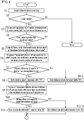
- FIG. 4 and FIG. 5 present a flowchart for outlining the distance data complementing process in the laser scanning sensor 100.
- the distance data acquisition unit 130 acquires distance data in all measurement directions at every measurement cycle (acquisition of distance data may also be called “scan”) (Step S1).
- the next step is to check whether the laser scanning sensor 100 is on alert or not (Step S2). If not on alert (NO in Step S2), the subsequent complementing process is unnecessary and the process is allowed to end.
- Step S2 If on alert (YES in Step S2), the distance data acquired in Step S1 in all measurement directions at one measurement cycle is checked, and the number of measurement directions which contain both the first distance value and the second distance value is counted (Step S3).
- Step 4 the count value is compared with a preset parameter (e.g. 50). If the count value is not over the preset parameter (NO in Step S4), the condition is not under heavy rain or thick fog and does not especially require the subsequent complementing process. Hence, the process is allowed to end.
- a preset parameter e.g. 50
- Step S4 If the count value exceeds the preset parameter (YES in Step S4), the process goes on to Step 5, where the measurement directions are grouped into either "the measurement direction in which both the first distance value and the second distance value are available (hereinafter abbreviated as “measurement direction with a second distance value”)" or “the measurement direction in which only the first distance value is available and the second distance value is not available (hereinafter abbreviated as “measurement direction without a second distance value”)", according to the counting in Step S3.
- Step 6 regarding the group of "measurement direction without a second distance value", calculation is made to obtain a distance difference between the first distance value and the distance to the outer periphery of the detection area A100, the latter distance having been stored in the memory 160 as reference distance data.
- Step 7 The judgment made in Step 7 is to determine whether the calculated distance difference is equal to or greater than a predetermined value. If the calculated distance difference is judged to be equal to or greater than the predetermined value (YES in Step S7), the distance data is stored in the temporary buffer "A" (Step S8-1). If not (NO in Step S7), the distance data is stored in the temporary buffer "B" (Step S8-2).
- Step 9 regarding the group of "measurement direction with a second distance value"
- calculation is made to obtain a distance difference between the second distance value and the distance to the outer periphery of the detection area A100.
- Step 10 The judgment made in Step 10 is to determine whether the calculated distance difference is equal to or greater than a predetermined value. If the calculated distance difference is judged to be equal to or greater than the predetermined value (YES in Step S10), the distance data is stored additionally in the temporary buffer "A" (Step S11-1). If not (NO in Step S10), the distance data is stored additionally in the temporary buffer "B" (Step S11-2).
- the complementing process is effected by substituting a complementary value (an interpolation value) for a piece of distance data in each measurement direction lacking distance data.
- a complementary value an interpolation value
- This complementary value, or interpolation value is based on pieces of distance data in the adjacent measurement directions on both sides (Step S15). Instead of the pieces of distance data in the adjacent measurement directions on both sides, a piece of distance data obtained in an earlier (for example, the most recent) measurement cycle in the very measurement direction lacking distance data may also be a complementary value (an extrapolation value).
- Step S16 judgment is made as to whether any distance data is present at a shorter distance than the distance data complemented in the complementing process. Even if such distance data is present at the shorter distance (YES in Step S16), the shorter distance data is ignored (Step S17).
- the distance data kept in the temporary buffer "B” is copied to the temporary buffer "A", with regard to all of the measurement directions that lack distance data in the temporary buffer "A” (Step S18).
- Step S19 the temporary buffer "A” is entirely copied to the data buffer for final use (Step S19), and a series of process comes to an end.
Applications Claiming Priority (2)
| Application Number | Priority Date | Filing Date | Title |
|---|---|---|---|
| JP2012205919A JP5540217B2 (ja) | 2012-09-19 | 2012-09-19 | レーザースキャンセンサ |
| PCT/JP2013/072978 WO2014045817A1 (ja) | 2012-09-19 | 2013-08-28 | レーザースキャンセンサ |
Publications (3)
| Publication Number | Publication Date |
|---|---|
| EP2899705A1 EP2899705A1 (en) | 2015-07-29 |
| EP2899705A4 EP2899705A4 (en) | 2016-06-29 |
| EP2899705B1 true EP2899705B1 (en) | 2017-12-06 |
Family
ID=50341139
Family Applications (1)
| Application Number | Title | Priority Date | Filing Date |
|---|---|---|---|
| EP13838772.5A Active EP2899705B1 (en) | 2012-09-19 | 2013-08-28 | Laser scan sensor |
Country Status (4)
| Country | Link |
|---|---|
| US (1) | US9733358B2 (ja) |
| EP (1) | EP2899705B1 (ja) |
| JP (1) | JP5540217B2 (ja) |
| WO (1) | WO2014045817A1 (ja) |
Cited By (1)
| Publication number | Priority date | Publication date | Assignee | Title |
|---|---|---|---|---|
| EP3715905A1 (de) | 2019-03-26 | 2020-09-30 | Sick Ag | Verfahren zum betreiben eines abstandsmessenden überwachungssensors und abstandsmessender überwachungssensor |
Families Citing this family (8)
| Publication number | Priority date | Publication date | Assignee | Title |
|---|---|---|---|---|
| EP3051310B1 (de) * | 2015-01-28 | 2017-03-01 | Riegl Laser Measurement Systems GmbH | Vorrichtung zum Objektschutz mittels Laserscannern |
| EP3220164B1 (de) * | 2016-03-14 | 2018-03-07 | Sick Ag | Verfahren zum betreiben eines abstandsmessenden überwachungssensors und überwachungssensor |
| WO2017169782A1 (ja) * | 2016-03-31 | 2017-10-05 | 富士フイルム株式会社 | 距離画像処理装置、距離画像取得装置、及び距離画像処理方法 |
| JP6821957B2 (ja) * | 2016-06-08 | 2021-01-27 | アイシン精機株式会社 | 測距装置 |
| JP6831550B2 (ja) | 2016-06-23 | 2021-02-17 | オプテックス株式会社 | レーザースキャンセンサ |
| TWI607672B (zh) * | 2017-03-27 | 2017-12-01 | 世大福智科技股份有限公司 | 應用於室內環境的緊急呼叫裝置、發光系統及其發光方法 |
| EP3617752B1 (en) * | 2018-08-27 | 2021-07-21 | Syncmold Enterprise Corp. | Detecting system and detecting method |
| JP7437743B2 (ja) | 2020-03-03 | 2024-02-26 | オプテックス株式会社 | レーザースキャンセンサ |
Family Cites Families (10)
| Publication number | Priority date | Publication date | Assignee | Title |
|---|---|---|---|---|
| JPS62296601A (ja) | 1986-06-17 | 1987-12-23 | Nippon Dengiyou Kosaku Kk | 低域通過ろ波器 |
| JP3011121B2 (ja) | 1997-02-28 | 2000-02-21 | 日本電気株式会社 | 警備システム |
| CA2320973A1 (en) | 1998-03-10 | 1999-09-16 | Riegl Laser Measurement Systems Gmbh | Method for monitoring objects or an object area |
| JP2000298172A (ja) * | 1999-04-15 | 2000-10-24 | Honda Motor Co Ltd | レーダ装置におけるデータ処理方法 |
| JP4644958B2 (ja) * | 2001-03-19 | 2011-03-09 | パナソニック電工株式会社 | 距離測定装置 |
| JP2003304613A (ja) * | 2002-04-05 | 2003-10-24 | Oputouea Kk | ギャロッピング計測装置 |
| JP2004185363A (ja) | 2002-12-04 | 2004-07-02 | Ishikawajima Harima Heavy Ind Co Ltd | エリアセンサによる物体識別方法 |
| JP4228132B2 (ja) * | 2002-10-18 | 2009-02-25 | 株式会社トプコン | 位置測定装置 |
| JP5136927B2 (ja) | 2007-10-09 | 2013-02-06 | オプテックス株式会社 | レーザエリアセンサ |
| JP5092076B2 (ja) * | 2007-10-26 | 2012-12-05 | オプテックス株式会社 | レーザエリアセンサ |
-
2012
- 2012-09-19 JP JP2012205919A patent/JP5540217B2/ja active Active
-
2013
- 2013-08-28 US US14/429,150 patent/US9733358B2/en active Active
- 2013-08-28 WO PCT/JP2013/072978 patent/WO2014045817A1/ja active Application Filing
- 2013-08-28 EP EP13838772.5A patent/EP2899705B1/en active Active
Non-Patent Citations (1)
| Title |
|---|
| None * |
Cited By (2)
| Publication number | Priority date | Publication date | Assignee | Title |
|---|---|---|---|---|
| EP3715905A1 (de) | 2019-03-26 | 2020-09-30 | Sick Ag | Verfahren zum betreiben eines abstandsmessenden überwachungssensors und abstandsmessender überwachungssensor |
| DE102019107681B4 (de) | 2019-03-26 | 2022-12-01 | Sick Ag | Verfahren zum Betreiben eines abstandsmessenden Überwachungssensors und abstandsmessender Überwachungssensor |
Also Published As
| Publication number | Publication date |
|---|---|
| JP2014059834A (ja) | 2014-04-03 |
| WO2014045817A1 (ja) | 2014-03-27 |
| EP2899705A1 (en) | 2015-07-29 |
| JP5540217B2 (ja) | 2014-07-02 |
| EP2899705A4 (en) | 2016-06-29 |
| US9733358B2 (en) | 2017-08-15 |
| US20150212209A1 (en) | 2015-07-30 |
Similar Documents
| Publication | Publication Date | Title |
|---|---|---|
| EP2899705B1 (en) | Laser scan sensor | |
| US7760336B2 (en) | Laser area sensor | |
| EP2053424B1 (en) | Target detecting device, target detecting method, and target detecting program | |
| US7940178B2 (en) | Laser area sensor | |
| US8681323B2 (en) | Laser scanning sensor | |
| US9182489B2 (en) | Laser scan sensor | |
| EP1778531B1 (en) | A monitoring device | |
| US9140793B2 (en) | Laser scan sensor | |
| US11899109B2 (en) | Laser scanning sensor | |
| JP2011048594A (ja) | 侵入者検知装置 | |
| CN114194985B (zh) | 一种tof电梯安全光幕报警区域的标定方法 |
Legal Events
| Date | Code | Title | Description |
|---|---|---|---|
| PUAI | Public reference made under article 153(3) epc to a published international application that has entered the european phase |
Free format text: ORIGINAL CODE: 0009012 |
|
| 17P | Request for examination filed |
Effective date: 20150417 |
|
| AK | Designated contracting states |
Kind code of ref document: A1 Designated state(s): AL AT BE BG CH CY CZ DE DK EE ES FI FR GB GR HR HU IE IS IT LI LT LU LV MC MK MT NL NO PL PT RO RS SE SI SK SM TR |
|
| AX | Request for extension of the european patent |
Extension state: BA ME |
|
| DAX | Request for extension of the european patent (deleted) | ||
| REG | Reference to a national code |
Ref country code: DE Ref legal event code: R079 Ref document number: 602013030569 Country of ref document: DE Free format text: PREVIOUS MAIN CLASS: G08B0013181000 Ipc: G08B0013187000 |
|
| RA4 | Supplementary search report drawn up and despatched (corrected) |
Effective date: 20160531 |
|
| RIC1 | Information provided on ipc code assigned before grant |
Ipc: G01S 7/481 20060101ALI20160524BHEP Ipc: G01S 7/48 20060101ALI20160524BHEP Ipc: G08B 13/187 20060101AFI20160524BHEP Ipc: G01S 17/42 20060101ALI20160524BHEP |
|
| GRAP | Despatch of communication of intention to grant a patent |
Free format text: ORIGINAL CODE: EPIDOSNIGR1 |
|
| INTG | Intention to grant announced |
Effective date: 20170623 |
|
| GRAS | Grant fee paid |
Free format text: ORIGINAL CODE: EPIDOSNIGR3 |
|
| GRAA | (expected) grant |
Free format text: ORIGINAL CODE: 0009210 |
|
| AK | Designated contracting states |
Kind code of ref document: B1 Designated state(s): AL AT BE BG CH CY CZ DE DK EE ES FI FR GB GR HR HU IE IS IT LI LT LU LV MC MK MT NL NO PL PT RO RS SE SI SK SM TR |
|
| REG | Reference to a national code |
Ref country code: GB Ref legal event code: FG4D |
|
| REG | Reference to a national code |
Ref country code: AT Ref legal event code: REF Ref document number: 953030 Country of ref document: AT Kind code of ref document: T Effective date: 20171215 Ref country code: CH Ref legal event code: EP |
|
| REG | Reference to a national code |
Ref country code: IE Ref legal event code: FG4D |
|
| REG | Reference to a national code |
Ref country code: DE Ref legal event code: R096 Ref document number: 602013030569 Country of ref document: DE |
|
| REG | Reference to a national code |
Ref country code: NL Ref legal event code: MP Effective date: 20171206 |
|
| REG | Reference to a national code |
Ref country code: LT Ref legal event code: MG4D |
|
| PG25 | Lapsed in a contracting state [announced via postgrant information from national office to epo] |
Ref country code: SE Free format text: LAPSE BECAUSE OF FAILURE TO SUBMIT A TRANSLATION OF THE DESCRIPTION OR TO PAY THE FEE WITHIN THE PRESCRIBED TIME-LIMIT Effective date: 20171206 Ref country code: ES Free format text: LAPSE BECAUSE OF FAILURE TO SUBMIT A TRANSLATION OF THE DESCRIPTION OR TO PAY THE FEE WITHIN THE PRESCRIBED TIME-LIMIT Effective date: 20171206 Ref country code: FI Free format text: LAPSE BECAUSE OF FAILURE TO SUBMIT A TRANSLATION OF THE DESCRIPTION OR TO PAY THE FEE WITHIN THE PRESCRIBED TIME-LIMIT Effective date: 20171206 Ref country code: LT Free format text: LAPSE BECAUSE OF FAILURE TO SUBMIT A TRANSLATION OF THE DESCRIPTION OR TO PAY THE FEE WITHIN THE PRESCRIBED TIME-LIMIT Effective date: 20171206 Ref country code: NO Free format text: LAPSE BECAUSE OF FAILURE TO SUBMIT A TRANSLATION OF THE DESCRIPTION OR TO PAY THE FEE WITHIN THE PRESCRIBED TIME-LIMIT Effective date: 20180306 |
|
| REG | Reference to a national code |
Ref country code: AT Ref legal event code: MK05 Ref document number: 953030 Country of ref document: AT Kind code of ref document: T Effective date: 20171206 |
|
| PG25 | Lapsed in a contracting state [announced via postgrant information from national office to epo] |
Ref country code: GR Free format text: LAPSE BECAUSE OF FAILURE TO SUBMIT A TRANSLATION OF THE DESCRIPTION OR TO PAY THE FEE WITHIN THE PRESCRIBED TIME-LIMIT Effective date: 20180307 Ref country code: RS Free format text: LAPSE BECAUSE OF FAILURE TO SUBMIT A TRANSLATION OF THE DESCRIPTION OR TO PAY THE FEE WITHIN THE PRESCRIBED TIME-LIMIT Effective date: 20171206 Ref country code: BG Free format text: LAPSE BECAUSE OF FAILURE TO SUBMIT A TRANSLATION OF THE DESCRIPTION OR TO PAY THE FEE WITHIN THE PRESCRIBED TIME-LIMIT Effective date: 20180306 Ref country code: HR Free format text: LAPSE BECAUSE OF FAILURE TO SUBMIT A TRANSLATION OF THE DESCRIPTION OR TO PAY THE FEE WITHIN THE PRESCRIBED TIME-LIMIT Effective date: 20171206 |
|
| PG25 | Lapsed in a contracting state [announced via postgrant information from national office to epo] |
Ref country code: NL Free format text: LAPSE BECAUSE OF FAILURE TO SUBMIT A TRANSLATION OF THE DESCRIPTION OR TO PAY THE FEE WITHIN THE PRESCRIBED TIME-LIMIT Effective date: 20171206 |
|
| REG | Reference to a national code |
Ref country code: FR Ref legal event code: PLFP Year of fee payment: 6 |
|
| PG25 | Lapsed in a contracting state [announced via postgrant information from national office to epo] |
Ref country code: CZ Free format text: LAPSE BECAUSE OF FAILURE TO SUBMIT A TRANSLATION OF THE DESCRIPTION OR TO PAY THE FEE WITHIN THE PRESCRIBED TIME-LIMIT Effective date: 20171206 Ref country code: EE Free format text: LAPSE BECAUSE OF FAILURE TO SUBMIT A TRANSLATION OF THE DESCRIPTION OR TO PAY THE FEE WITHIN THE PRESCRIBED TIME-LIMIT Effective date: 20171206 Ref country code: SK Free format text: LAPSE BECAUSE OF FAILURE TO SUBMIT A TRANSLATION OF THE DESCRIPTION OR TO PAY THE FEE WITHIN THE PRESCRIBED TIME-LIMIT Effective date: 20171206 |
|
| PG25 | Lapsed in a contracting state [announced via postgrant information from national office to epo] |
Ref country code: RO Free format text: LAPSE BECAUSE OF FAILURE TO SUBMIT A TRANSLATION OF THE DESCRIPTION OR TO PAY THE FEE WITHIN THE PRESCRIBED TIME-LIMIT Effective date: 20171206 Ref country code: PL Free format text: LAPSE BECAUSE OF FAILURE TO SUBMIT A TRANSLATION OF THE DESCRIPTION OR TO PAY THE FEE WITHIN THE PRESCRIBED TIME-LIMIT Effective date: 20171206 Ref country code: AT Free format text: LAPSE BECAUSE OF FAILURE TO SUBMIT A TRANSLATION OF THE DESCRIPTION OR TO PAY THE FEE WITHIN THE PRESCRIBED TIME-LIMIT Effective date: 20171206 Ref country code: SM Free format text: LAPSE BECAUSE OF FAILURE TO SUBMIT A TRANSLATION OF THE DESCRIPTION OR TO PAY THE FEE WITHIN THE PRESCRIBED TIME-LIMIT Effective date: 20171206 |
|
| REG | Reference to a national code |
Ref country code: DE Ref legal event code: R097 Ref document number: 602013030569 Country of ref document: DE |
|
| PLBE | No opposition filed within time limit |
Free format text: ORIGINAL CODE: 0009261 |
|
| STAA | Information on the status of an ep patent application or granted ep patent |
Free format text: STATUS: NO OPPOSITION FILED WITHIN TIME LIMIT |
|
| 26N | No opposition filed |
Effective date: 20180907 |
|
| PG25 | Lapsed in a contracting state [announced via postgrant information from national office to epo] |
Ref country code: DK Free format text: LAPSE BECAUSE OF FAILURE TO SUBMIT A TRANSLATION OF THE DESCRIPTION OR TO PAY THE FEE WITHIN THE PRESCRIBED TIME-LIMIT Effective date: 20171206 Ref country code: SI Free format text: LAPSE BECAUSE OF FAILURE TO SUBMIT A TRANSLATION OF THE DESCRIPTION OR TO PAY THE FEE WITHIN THE PRESCRIBED TIME-LIMIT Effective date: 20171206 |
|
| PG25 | Lapsed in a contracting state [announced via postgrant information from national office to epo] |
Ref country code: MC Free format text: LAPSE BECAUSE OF FAILURE TO SUBMIT A TRANSLATION OF THE DESCRIPTION OR TO PAY THE FEE WITHIN THE PRESCRIBED TIME-LIMIT Effective date: 20171206 |
|
| REG | Reference to a national code |
Ref country code: CH Ref legal event code: PL |
|
| PG25 | Lapsed in a contracting state [announced via postgrant information from national office to epo] |
Ref country code: LI Free format text: LAPSE BECAUSE OF NON-PAYMENT OF DUE FEES Effective date: 20180831 Ref country code: LU Free format text: LAPSE BECAUSE OF NON-PAYMENT OF DUE FEES Effective date: 20180828 Ref country code: CH Free format text: LAPSE BECAUSE OF NON-PAYMENT OF DUE FEES Effective date: 20180831 |
|
| REG | Reference to a national code |
Ref country code: BE Ref legal event code: MM Effective date: 20180831 |
|
| PG25 | Lapsed in a contracting state [announced via postgrant information from national office to epo] |
Ref country code: BE Free format text: LAPSE BECAUSE OF NON-PAYMENT OF DUE FEES Effective date: 20180831 |
|
| PG25 | Lapsed in a contracting state [announced via postgrant information from national office to epo] |
Ref country code: MT Free format text: LAPSE BECAUSE OF NON-PAYMENT OF DUE FEES Effective date: 20180828 |
|
| PG25 | Lapsed in a contracting state [announced via postgrant information from national office to epo] |
Ref country code: TR Free format text: LAPSE BECAUSE OF FAILURE TO SUBMIT A TRANSLATION OF THE DESCRIPTION OR TO PAY THE FEE WITHIN THE PRESCRIBED TIME-LIMIT Effective date: 20171206 |
|
| PG25 | Lapsed in a contracting state [announced via postgrant information from national office to epo] |
Ref country code: PT Free format text: LAPSE BECAUSE OF FAILURE TO SUBMIT A TRANSLATION OF THE DESCRIPTION OR TO PAY THE FEE WITHIN THE PRESCRIBED TIME-LIMIT Effective date: 20171206 |
|
| PG25 | Lapsed in a contracting state [announced via postgrant information from national office to epo] |
Ref country code: MK Free format text: LAPSE BECAUSE OF NON-PAYMENT OF DUE FEES Effective date: 20171206 Ref country code: IE Free format text: LAPSE BECAUSE OF NON-PAYMENT OF DUE FEES Effective date: 20180828 Ref country code: HU Free format text: LAPSE BECAUSE OF FAILURE TO SUBMIT A TRANSLATION OF THE DESCRIPTION OR TO PAY THE FEE WITHIN THE PRESCRIBED TIME-LIMIT; INVALID AB INITIO Effective date: 20130828 Ref country code: CY Free format text: LAPSE BECAUSE OF FAILURE TO SUBMIT A TRANSLATION OF THE DESCRIPTION OR TO PAY THE FEE WITHIN THE PRESCRIBED TIME-LIMIT Effective date: 20171206 |
|
| PG25 | Lapsed in a contracting state [announced via postgrant information from national office to epo] |
Ref country code: AL Free format text: LAPSE BECAUSE OF FAILURE TO SUBMIT A TRANSLATION OF THE DESCRIPTION OR TO PAY THE FEE WITHIN THE PRESCRIBED TIME-LIMIT Effective date: 20171206 Ref country code: IS Free format text: LAPSE BECAUSE OF FAILURE TO SUBMIT A TRANSLATION OF THE DESCRIPTION OR TO PAY THE FEE WITHIN THE PRESCRIBED TIME-LIMIT Effective date: 20180406 |
|
| PGFP | Annual fee paid to national office [announced via postgrant information from national office to epo] |
Ref country code: IT Payment date: 20230825 Year of fee payment: 11 Ref country code: GB Payment date: 20230822 Year of fee payment: 11 |
|
| PGFP | Annual fee paid to national office [announced via postgrant information from national office to epo] |
Ref country code: FR Payment date: 20230824 Year of fee payment: 11 Ref country code: DE Payment date: 20230821 Year of fee payment: 11 |
|
| PGFP | Annual fee paid to national office [announced via postgrant information from national office to epo] |
Ref country code: LV Payment date: 20230816 Year of fee payment: 11 |