EP2899476B1 - Support assembly for mounting a solar panel unit - Google Patents
Support assembly for mounting a solar panel unit Download PDFInfo
- Publication number
- EP2899476B1 EP2899476B1 EP14185698.9A EP14185698A EP2899476B1 EP 2899476 B1 EP2899476 B1 EP 2899476B1 EP 14185698 A EP14185698 A EP 14185698A EP 2899476 B1 EP2899476 B1 EP 2899476B1
- Authority
- EP
- European Patent Office
- Prior art keywords
- tubes
- base
- support assembly
- unit
- supporting
- Prior art date
- Legal status (The legal status is an assumption and is not a legal conclusion. Google has not performed a legal analysis and makes no representation as to the accuracy of the status listed.)
- Active
Links
Images

Classifications
-
- H—ELECTRICITY
- H02—GENERATION; CONVERSION OR DISTRIBUTION OF ELECTRIC POWER
- H02S—GENERATION OF ELECTRIC POWER BY CONVERSION OF INFRARED RADIATION, VISIBLE LIGHT OR ULTRAVIOLET LIGHT, e.g. USING PHOTOVOLTAIC [PV] MODULES
- H02S20/00—Supporting structures for PV modules
- H02S20/10—Supporting structures directly fixed to the ground
-
- F—MECHANICAL ENGINEERING; LIGHTING; HEATING; WEAPONS; BLASTING
- F24—HEATING; RANGES; VENTILATING
- F24S—SOLAR HEAT COLLECTORS; SOLAR HEAT SYSTEMS
- F24S25/00—Arrangement of stationary mountings or supports for solar heat collector modules
- F24S25/10—Arrangement of stationary mountings or supports for solar heat collector modules extending in directions away from a supporting surface
- F24S25/13—Profile arrangements, e.g. trusses
-
- F—MECHANICAL ENGINEERING; LIGHTING; HEATING; WEAPONS; BLASTING
- F24—HEATING; RANGES; VENTILATING
- F24S—SOLAR HEAT COLLECTORS; SOLAR HEAT SYSTEMS
- F24S25/00—Arrangement of stationary mountings or supports for solar heat collector modules
- F24S25/60—Fixation means, e.g. fasteners, specially adapted for supporting solar heat collector modules
- F24S25/61—Fixation means, e.g. fasteners, specially adapted for supporting solar heat collector modules for fixing to the ground or to building structures
- F24S25/617—Elements driven into the ground, e.g. anchor-piles; Foundations for supporting elements; Connectors for connecting supporting structures to the ground or to flat horizontal surfaces
-
- F—MECHANICAL ENGINEERING; LIGHTING; HEATING; WEAPONS; BLASTING
- F24—HEATING; RANGES; VENTILATING
- F24S—SOLAR HEAT COLLECTORS; SOLAR HEAT SYSTEMS
- F24S25/00—Arrangement of stationary mountings or supports for solar heat collector modules
- F24S25/60—Fixation means, e.g. fasteners, specially adapted for supporting solar heat collector modules
- F24S25/65—Fixation means, e.g. fasteners, specially adapted for supporting solar heat collector modules for coupling adjacent supporting elements, e.g. for connecting profiles together
-
- F—MECHANICAL ENGINEERING; LIGHTING; HEATING; WEAPONS; BLASTING
- F24—HEATING; RANGES; VENTILATING
- F24S—SOLAR HEAT COLLECTORS; SOLAR HEAT SYSTEMS
- F24S25/00—Arrangement of stationary mountings or supports for solar heat collector modules
- F24S2025/01—Special support components; Methods of use
- F24S2025/02—Ballasting means
-
- F—MECHANICAL ENGINEERING; LIGHTING; HEATING; WEAPONS; BLASTING
- F24—HEATING; RANGES; VENTILATING
- F24S—SOLAR HEAT COLLECTORS; SOLAR HEAT SYSTEMS
- F24S25/00—Arrangement of stationary mountings or supports for solar heat collector modules
- F24S2025/80—Special profiles
- F24S2025/802—Special profiles having circular or oval cross-section
-
- Y—GENERAL TAGGING OF NEW TECHNOLOGICAL DEVELOPMENTS; GENERAL TAGGING OF CROSS-SECTIONAL TECHNOLOGIES SPANNING OVER SEVERAL SECTIONS OF THE IPC; TECHNICAL SUBJECTS COVERED BY FORMER USPC CROSS-REFERENCE ART COLLECTIONS [XRACs] AND DIGESTS
- Y02—TECHNOLOGIES OR APPLICATIONS FOR MITIGATION OR ADAPTATION AGAINST CLIMATE CHANGE
- Y02E—REDUCTION OF GREENHOUSE GAS [GHG] EMISSIONS, RELATED TO ENERGY GENERATION, TRANSMISSION OR DISTRIBUTION
- Y02E10/00—Energy generation through renewable energy sources
- Y02E10/40—Solar thermal energy, e.g. solar towers
- Y02E10/47—Mountings or tracking
-
- Y—GENERAL TAGGING OF NEW TECHNOLOGICAL DEVELOPMENTS; GENERAL TAGGING OF CROSS-SECTIONAL TECHNOLOGIES SPANNING OVER SEVERAL SECTIONS OF THE IPC; TECHNICAL SUBJECTS COVERED BY FORMER USPC CROSS-REFERENCE ART COLLECTIONS [XRACs] AND DIGESTS
- Y02—TECHNOLOGIES OR APPLICATIONS FOR MITIGATION OR ADAPTATION AGAINST CLIMATE CHANGE
- Y02E—REDUCTION OF GREENHOUSE GAS [GHG] EMISSIONS, RELATED TO ENERGY GENERATION, TRANSMISSION OR DISTRIBUTION
- Y02E10/00—Energy generation through renewable energy sources
- Y02E10/50—Photovoltaic [PV] energy
Definitions
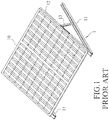
- Taiwanese Utility Model Patent No. M408023 discloses a conventional support assembly 1 for mounting a solar panel unit 10.
- the conventional support assembly 1 includes a supporting frame 12, two supporting brackets 11 that are connected to the supporting frame 12, and two supporting rods 13 (only one is shown in Fig. 1 due to the view angle) each interconnecting the corresponding supporting bracket 11 and the supporting frame 12 such that the supporting frame 12 is inclined.
- the supporting frame 12 is configured for mounting the solar panel unit 10.
- the supporting brackets 11 are adapted to be mounted on a ground (not shown).
- the solar panel unit 10 cannot be firmly mounted on the ground if the ground surface is not flat. Therefore, a flat cement ground has to be built in advance. Since the support assembly 1 has to be transported along with the cement, the transporting cost is relatively high. Moreover, when the support assembly 1 has to be removed, the cement ground also has to be torn down. To tear down the cement ground results in waste of time and cost.
- the object of the present invention is to provide a support assembly that can overcome at least one of the aforesaid drawbacks of the prior art.
- a support assembly for mounting a solar panel unit includes a base unit and a supporting unit.
- the base unit includes a plurality of base tubes that are spaced apart from one another and two connecting tubes that are respectively and detachably connected to opposite end portions of each of the base tubes.
- the supporting unit includes a plurality of limiting components and a plurality of supporting rods. Each limiting component permits at least two of the base tubes to extend therethrough so as to position the at least two of the base tubes relative to each other.
- Each supporting rod is detachably connected to and extends upwardly from a corresponding one of the limiting components and is adapted for supporting the solar panel unit thereon.
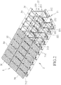
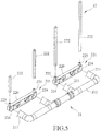
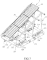
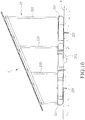
- the exemplary support assembly 2 for mounting a solar panel unit 3 on a ground 4 (see Fig. 10 ) is shown to include a base unit 21 and a supporting unit 22.
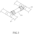
- the base unit 21 includes a plurality of base tubes 211 that are spaced apart from one another, two connecting tubes 212 that are respectively and detachably connected to opposite end portions of each of the base tubes 211, and a reinforcing tube 213 that interconnects two of the base tubes 211 for reinforcing a structural strength of the base unit 21.
- the base tubes 211 and the connecting tubes 212 are arranged in an array so as to increase the contact area between the base unit 21 and the ground 4, so that the base unit 21 can be firmly mounted on the ground 4 by virtue of its own weight.
- the number of the connecting reinforcing tube 213 can be increased (i.e., the number of the reinforcing tube 213 may be two, three, or more) for further reinforcing the structural strength of the base unit 21 to meet actual requirements.
- the supporting unit 22 includes a plurality of limiting components 221 and a plurality of supporting rods 222.
- Each limiting component 221 permits two the base tubes 211 to extend therethrough so as to position the two of the base tubes 211 relative to each other.
- Each supporting rod 222 is detachably connected to and extends upwardly from a corresponding one of the limiting components 221, and is adapted for supporting the solar panel unit 3 thereon.
- the supporting rods 222 are arranged in a plurality of rows.
- the supporting rods 222 of each row are arranged along a direction parallel to the connecting tubes 212.
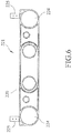
- each limiting component 221 has a main body portion 220 that is formed with two through holes 224 spaced apart from each other, and two extending portions 225 that are spaced apart from each other and that extend upwardly from the main body portion 220.
- Each through hole 224 is disposed for permitting a respective one of the base tubes 211 to extend therethrough.
- Each extending portion 225 is disposed for permitting a respective one of the supporting rods 222 to be sleeved fixedly thereon.
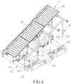
- the supporting rods 222 of each row have different lengths such that the solar panel unit 3 can be mounted on the supporting rods 222 at an inclination angle.
- the solar panel unit 3 includes a plurality of solar panels 30.
- the assembling process of the exemplary support assembly 2 includes the following steps of: extending each base tube 211 through the corresponding one of the through holes 224 of the main body portions 220; respectively connecting the connecting tubes 212 to the opposite end portions of each of the base tubes 211; sleeving each supporting rod 222 on the corresponding one of the extending portions 225 of the limiting components 221; and mounting the solar panel unit 3 on the supporting rods 222 (see Fig. 4 ). It should be noted that, in this example, there is no need for building a cement ground in advance which is required for the above-mentioned prior art.
- the disassembling process of the exemplary support assembly 2 includes the following steps of: separating the solar panel unit 3 and the supporting rods 222; separating the supporting rods 222 and the extending portions 225 of the limiting components 221; separating the connecting tubes 212 and the base tubes 211; and separating the base tubes 211 from the through holes 224 of the main body portions 220. Since the support assembly 2 is simple to assemble/disassemble repeatedly, it is convenient for a user to transport the support assembly 2.
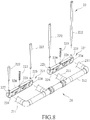
- the embodiment of a support assembly 2 for mounting a solar panel unit 3 has a structure similar to that of the exemplary support assembly, except that the main body portion 220 of each of the limiting components 221 is further formed with an aperture 226, the supporting unit 22 further includes a plurality of positioning components 223, and the base unit 21 further includes a charging valve 214.
- each positioning component 223 extends through the aperture 226 of the main body portion 220 of a respective one of the limiting components 221 and is adapted to extend into the ground 4 for mounting fixedly a corresponding one of the limiting components 221 on the ground 4 (see Fig. 10 ).
- Each positioning component 223 is, for example but not limited to, a spiral anchor.
- the base tubes 211 are in spatial communication with and connected sealingly to the connecting tubes 212.
- the charging valve 214 is disposed on one of the base tubes 211 and is operable for forcing liquid from the outside into the base tubes 211 and the connecting tubes 212. It should be noted that, in a variation of this embodiment, the charging valve 214 may also be disposed on one of the connecting tubes 212.
- the assembling process of the embodiment of the support assembly 2 is similar to that of the exemplary support assembly, except that it further includes a step of extending each positioning component 223 through the aperture 226 of the main body portion 220 of a respective one of the limiting components 221, and forcing the liquid from the outside into the base tubs 211 and the connecting tubes 212 through operation of the charging valve 214.
- the liquid is, for example but not limited to, water.
- the limiting components 221 can be firmly and fixedly mounted on the ground 4.
- the liquid that is pumped into the base tubes 211 and the connecting tubes 212 increases the weight of the whole structure so as to prevent the support assembly 2 from inclining.
- the disassembling process of the embodiment of the support assembly 2 is similar to that of the exemplary support assembly, except that it further includes a step of separating the positioning components 223 form the ground 4 and the through holes 226. It should be noted that the liquid can be obtained at the place to assemble the support assembly 2. That is to say, there is no need to transport the liquid along with the support assembly 2, thereby reducing the total transported weight.
Landscapes
- Engineering & Computer Science (AREA)
- Chemical & Material Sciences (AREA)
- Life Sciences & Earth Sciences (AREA)
- Sustainable Development (AREA)
- Sustainable Energy (AREA)
- Thermal Sciences (AREA)
- Physics & Mathematics (AREA)
- Combustion & Propulsion (AREA)
- Mechanical Engineering (AREA)
- General Engineering & Computer Science (AREA)
- Photovoltaic Devices (AREA)
- Information Transfer Systems (AREA)
- Roof Covering Using Slabs Or Stiff Sheets (AREA)
Priority Applications (1)
| Application Number | Priority Date | Filing Date | Title |
|---|---|---|---|
| PL14185698T PL2899476T3 (pl) | 2014-01-28 | 2014-09-22 | Zespół wsporczy do montażu jednostki panelu solarnego |
Applications Claiming Priority (1)
| Application Number | Priority Date | Filing Date | Title |
|---|---|---|---|
| TW103201841U TWM483397U (zh) | 2014-01-28 | 2014-01-28 | 用於安裝太陽能板的組合式基座 |
Publications (2)
| Publication Number | Publication Date |
|---|---|
| EP2899476A1 EP2899476A1 (en) | 2015-07-29 |
| EP2899476B1 true EP2899476B1 (en) | 2019-02-06 |
Family
ID=51793077
Family Applications (1)
| Application Number | Title | Priority Date | Filing Date |
|---|---|---|---|
| EP14185698.9A Active EP2899476B1 (en) | 2014-01-28 | 2014-09-22 | Support assembly for mounting a solar panel unit |
Country Status (6)
| Country | Link |
|---|---|
| US (1) | US9444395B2 (pl) |
| EP (1) | EP2899476B1 (pl) |
| JP (1) | JP3192454U (pl) |
| PL (1) | PL2899476T3 (pl) |
| TR (1) | TR201906029T4 (pl) |
| TW (1) | TWM483397U (pl) |
Families Citing this family (11)
| Publication number | Priority date | Publication date | Assignee | Title |
|---|---|---|---|---|
| US10727781B2 (en) * | 2014-12-24 | 2020-07-28 | Ecolibrium Solar, Inc. | Low-sloped roof solar mounting systems |
| TWM511603U (zh) | 2015-05-28 | 2015-11-01 | Sun Rise E&T Corp | 模組化太陽能發電系統 |
| KR101757207B1 (ko) * | 2015-08-18 | 2017-07-12 | 주식회사 더블유쏠라 | 태양광 발전 시스템 |
| US10230324B2 (en) * | 2016-03-07 | 2019-03-12 | Ecolibrium Solar, Inc | Support assembly for photovoltaic modules and mounting system using the same |
| US9923513B2 (en) * | 2016-05-13 | 2018-03-20 | Boson Robotics Ltd. | Cleaning mechanism having water spray function and photovoltaic panel cleaning equipment having same |
| TWI597933B (zh) * | 2016-09-06 | 2017-09-01 | Solar panel support | |
| AU2018299914B2 (en) * | 2017-07-10 | 2023-09-28 | Nuance Energy Group, Inc. | Transportable and multi configurable, modular power platforms |
| US11319035B2 (en) * | 2018-02-26 | 2022-05-03 | Sunny Rich Agric. & Biotech Co., Ltd. | Floating type solar power generation equipment stage device |
| US12143062B2 (en) * | 2022-03-04 | 2024-11-12 | Joseph Sponsler | Apparatus and method for solar energy collector |
| USD1089062S1 (en) * | 2023-12-11 | 2025-08-19 | Rodger Seratt | Solar panel structure |
| TWI883791B (zh) * | 2024-01-17 | 2025-05-11 | 旭東環保科技股份有限公司 | 離岸太陽能光電的減風消浪圍堰裝置及其系統 |
Family Cites Families (29)
| Publication number | Priority date | Publication date | Assignee | Title |
|---|---|---|---|---|
| US4269173A (en) * | 1978-04-27 | 1981-05-26 | Libbey-Owens-Ford Company | System for mounting solar collector panels |
| US4226256A (en) * | 1979-09-18 | 1980-10-07 | Atlantic Richfield Company | Solar panel assembly and support pad |
| US4374406A (en) * | 1981-07-10 | 1983-02-15 | James Hepp | Lightweight attachment for solar cell array next to a fluorescent tube |
| US4421943A (en) * | 1982-02-19 | 1983-12-20 | Cities Service Company | Collapsible mobile solar energy power source |
| EP0466708A4 (en) * | 1989-04-25 | 1992-11-19 | Glasstech, Inc. | Photovoltaic panel support assembly |
| US4999059A (en) * | 1989-08-11 | 1991-03-12 | Bagno Robert G | Universal solar concentrator panel |
| US5244508A (en) * | 1992-04-02 | 1993-09-14 | The United States Of America As Represented By The Administrator Of The National Aeronautics And Space Administration | Self-deploying photovoltaic power system |
| US6201181B1 (en) * | 1998-12-08 | 2001-03-13 | Ase Americas, Inc. | Portable solar module cart |
| US20020124447A1 (en) * | 1999-11-19 | 2002-09-12 | Burke Edward Allen | Mast-supported display system |
| US6629389B1 (en) * | 2000-05-01 | 2003-10-07 | Marcus D. Rust | Security anchoring device |
| WO2005119133A2 (en) * | 2004-06-02 | 2005-12-15 | Energy Innovations, Inc. | Solar collector mounting array |
| US7481211B2 (en) * | 2005-04-27 | 2009-01-27 | Quixotic Systems, Inc. | Solar panel mounting structure |
| US8832938B2 (en) * | 2008-03-27 | 2014-09-16 | Panelclaw, Inc. | Ground mounted solar module integration system |
| US20100089390A1 (en) * | 2008-10-13 | 2010-04-15 | Sunlink, Corp | Solar array mounting system |
| US20100269888A1 (en) * | 2009-04-27 | 2010-10-28 | Johnston Jr Robert G | System for mounting and selectable adjustment of angle of elevation of groups of PV panels |
| US8770885B2 (en) * | 2009-05-27 | 2014-07-08 | Melvin L. Myers | Wedge clamp |
| US8191320B2 (en) * | 2009-10-15 | 2012-06-05 | Sunlink Corporation | Photovoltaic panel clamp |
| US8615939B2 (en) * | 2009-10-15 | 2013-12-31 | Sunlink Corporation | Photovoltaic module mounting system |
| US8156697B2 (en) * | 2009-10-15 | 2012-04-17 | Sunlink Corporation | Photovoltaic module mounting system |
| JP5414783B2 (ja) * | 2009-12-25 | 2014-02-12 | 株式会社屋根技術研究所 | 補助部材 |
| US8295033B2 (en) * | 2010-01-21 | 2012-10-23 | George Van Straten | Mobile electricity generator using solar, wind, and fuel-generated power |
| US20110233157A1 (en) * | 2010-03-22 | 2011-09-29 | JAC-Rack, Inc. | Solar panel mounting system and method |
| DE212011100099U1 (de) * | 2010-05-24 | 2013-03-04 | Peter Fuchs | Solarmodul-System |
| WO2012018360A1 (en) * | 2010-08-06 | 2012-02-09 | First Solar, Inc. | Folding mount for photovoltaic modules |
| TWM408023U (en) | 2010-10-08 | 2011-07-21 | Sun Rise E & T Corp | Supporting device of solar panel |
| CN202120929U (zh) * | 2011-05-31 | 2012-01-18 | 永盛(山东)能源有限公司 | 浮力式太阳能单元及浮力式太阳能装置 |
| US20130000693A1 (en) * | 2011-06-30 | 2013-01-03 | Google Inc. | Solar Positioning System and Method |
| JP6040242B2 (ja) * | 2011-08-15 | 2016-12-07 | モーガン ソーラー インコーポレーテッド | 自己安定型の太陽光追尾装置 |
| US8713881B2 (en) * | 2012-01-27 | 2014-05-06 | A. Raymond Et Cie | Solar panel securing system |
-
2014
- 2014-01-28 TW TW103201841U patent/TWM483397U/zh not_active IP Right Cessation
- 2014-06-05 JP JP2014002959U patent/JP3192454U/ja not_active Expired - Lifetime
- 2014-09-22 TR TR2019/06029T patent/TR201906029T4/tr unknown
- 2014-09-22 EP EP14185698.9A patent/EP2899476B1/en active Active
- 2014-09-22 PL PL14185698T patent/PL2899476T3/pl unknown
- 2014-10-01 US US14/504,129 patent/US9444395B2/en active Active
Non-Patent Citations (1)
| Title |
|---|
| None * |
Also Published As
| Publication number | Publication date |
|---|---|
| PL2899476T3 (pl) | 2019-08-30 |
| US9444395B2 (en) | 2016-09-13 |
| EP2899476A1 (en) | 2015-07-29 |
| JP3192454U (ja) | 2014-08-14 |
| TWM483397U (zh) | 2014-08-01 |
| US20150214883A1 (en) | 2015-07-30 |
| TR201906029T4 (tr) | 2019-05-21 |
Similar Documents
| Publication | Publication Date | Title |
|---|---|---|
| EP2899476B1 (en) | Support assembly for mounting a solar panel unit | |
| US20090062078A1 (en) | Flexible Enclosure For A Recreational Structure | |
| JP3205385U (ja) | ソーラーパネル設置用プラットフォーム | |
| EP2030654A2 (en) | Safety enclosure | |
| US9220340B2 (en) | Bathroom shelf assembly and bathroom shelf having the same | |
| GR1008008B (el) | Συστημα κατασκευης βασεων στηριξης φωτοβολταϊκων στοιχειων με ειδικο πολυσυνδεσμο κατασκευης τριγωνικων στοιχειων | |
| JP5959837B2 (ja) | 太陽光モジュール取付架台用ユニット | |
| JP6493809B2 (ja) | 太陽電池システム | |
| KR101867079B1 (ko) | 방향 조절이 가능한 울타리와 기둥 체결장치 | |
| KR101029360B1 (ko) | 파고라의 기둥구조 | |
| CN206813302U (zh) | 一种无人机 | |
| JP5311696B1 (ja) | 木造建築物の補強体 | |
| KR101522810B1 (ko) | 조립이 간편하고 견고한 돔 커넥터 | |
| EP3739138B1 (en) | A playground | |
| JP2008095311A (ja) | フェンス用継手 | |
| CN211336185U (zh) | 无人车机架及无人车 | |
| TWM600378U (zh) | 防風罩之定位結構 | |
| JP3178235U (ja) | トイレの仕切り板の支持スタンド | |
| JP6523680B2 (ja) | 太陽電池モジュール用の架台及びそれを備えた太陽電池モジュールの設置体 | |
| US20150295533A1 (en) | Ballasted fixed tilt racking system | |
| JP2014190050A (ja) | 落雪防止装置 | |
| JP6277220B2 (ja) | ユニットハウス用カプセル支持構造 | |
| EP1832498A3 (en) | Transport vehicle chassis | |
| JP5829657B2 (ja) | 太陽電池モジュール設置具 | |
| JP6332754B2 (ja) | ラックの連結部材取付け構造 |
Legal Events
| Date | Code | Title | Description |
|---|---|---|---|
| PUAI | Public reference made under article 153(3) epc to a published international application that has entered the european phase |
Free format text: ORIGINAL CODE: 0009012 |
|
| 17P | Request for examination filed |
Effective date: 20140922 |
|
| AK | Designated contracting states |
Kind code of ref document: A1 Designated state(s): AL AT BE BG CH CY CZ DE DK EE ES FI FR GB GR HR HU IE IS IT LI LT LU LV MC MK MT NL NO PL PT RO RS SE SI SK SM TR |
|
| AX | Request for extension of the european patent |
Extension state: BA ME |
|
| 17P | Request for examination filed |
Effective date: 20160129 |
|
| RBV | Designated contracting states (corrected) |
Designated state(s): AL AT BE BG CH CY CZ DE DK EE ES FI FR GB GR HR HU IE IS IT LI LT LU LV MC MK MT NL NO PL PT RO RS SE SI SK SM TR |
|
| REG | Reference to a national code |
Ref country code: DE Ref legal event code: R079 Ref document number: 602014040674 Country of ref document: DE Free format text: PREVIOUS MAIN CLASS: F24J0002520000 Ipc: F24S0025130000 |
|
| GRAP | Despatch of communication of intention to grant a patent |
Free format text: ORIGINAL CODE: EPIDOSNIGR1 |
|
| STAA | Information on the status of an ep patent application or granted ep patent |
Free format text: STATUS: GRANT OF PATENT IS INTENDED |
|
| RIC1 | Information provided on ipc code assigned before grant |
Ipc: F24S 25/65 20180101ALI20180730BHEP Ipc: F24S 25/617 20180101ALI20180730BHEP Ipc: F24S 25/13 20180101AFI20180730BHEP |
|
| INTG | Intention to grant announced |
Effective date: 20180821 |
|
| GRAS | Grant fee paid |
Free format text: ORIGINAL CODE: EPIDOSNIGR3 |
|
| GRAA | (expected) grant |
Free format text: ORIGINAL CODE: 0009210 |
|
| STAA | Information on the status of an ep patent application or granted ep patent |
Free format text: STATUS: THE PATENT HAS BEEN GRANTED |
|
| AK | Designated contracting states |
Kind code of ref document: B1 Designated state(s): AL AT BE BG CH CY CZ DE DK EE ES FI FR GB GR HR HU IE IS IT LI LT LU LV MC MK MT NL NO PL PT RO RS SE SI SK SM TR |
|
| REG | Reference to a national code |
Ref country code: GB Ref legal event code: FG4D |
|
| REG | Reference to a national code |
Ref country code: CH Ref legal event code: EP Ref country code: AT Ref legal event code: REF Ref document number: 1095163 Country of ref document: AT Kind code of ref document: T Effective date: 20190215 |
|
| REG | Reference to a national code |
Ref country code: IE Ref legal event code: FG4D |
|
| REG | Reference to a national code |
Ref country code: DE Ref legal event code: R096 Ref document number: 602014040674 Country of ref document: DE |
|
| REG | Reference to a national code |
Ref country code: NL Ref legal event code: MP Effective date: 20190206 |
|
| REG | Reference to a national code |
Ref country code: LT Ref legal event code: MG4D |
|
| PG25 | Lapsed in a contracting state [announced via postgrant information from national office to epo] |
Ref country code: FI Free format text: LAPSE BECAUSE OF FAILURE TO SUBMIT A TRANSLATION OF THE DESCRIPTION OR TO PAY THE FEE WITHIN THE PRESCRIBED TIME-LIMIT Effective date: 20190206 Ref country code: NO Free format text: LAPSE BECAUSE OF FAILURE TO SUBMIT A TRANSLATION OF THE DESCRIPTION OR TO PAY THE FEE WITHIN THE PRESCRIBED TIME-LIMIT Effective date: 20190506 Ref country code: SE Free format text: LAPSE BECAUSE OF FAILURE TO SUBMIT A TRANSLATION OF THE DESCRIPTION OR TO PAY THE FEE WITHIN THE PRESCRIBED TIME-LIMIT Effective date: 20190206 Ref country code: PT Free format text: LAPSE BECAUSE OF FAILURE TO SUBMIT A TRANSLATION OF THE DESCRIPTION OR TO PAY THE FEE WITHIN THE PRESCRIBED TIME-LIMIT Effective date: 20190606 Ref country code: LT Free format text: LAPSE BECAUSE OF FAILURE TO SUBMIT A TRANSLATION OF THE DESCRIPTION OR TO PAY THE FEE WITHIN THE PRESCRIBED TIME-LIMIT Effective date: 20190206 Ref country code: NL Free format text: LAPSE BECAUSE OF FAILURE TO SUBMIT A TRANSLATION OF THE DESCRIPTION OR TO PAY THE FEE WITHIN THE PRESCRIBED TIME-LIMIT Effective date: 20190206 |
|
| REG | Reference to a national code |
Ref country code: AT Ref legal event code: MK05 Ref document number: 1095163 Country of ref document: AT Kind code of ref document: T Effective date: 20190206 |
|
| PG25 | Lapsed in a contracting state [announced via postgrant information from national office to epo] |
Ref country code: LV Free format text: LAPSE BECAUSE OF FAILURE TO SUBMIT A TRANSLATION OF THE DESCRIPTION OR TO PAY THE FEE WITHIN THE PRESCRIBED TIME-LIMIT Effective date: 20190206 Ref country code: HR Free format text: LAPSE BECAUSE OF FAILURE TO SUBMIT A TRANSLATION OF THE DESCRIPTION OR TO PAY THE FEE WITHIN THE PRESCRIBED TIME-LIMIT Effective date: 20190206 Ref country code: BG Free format text: LAPSE BECAUSE OF FAILURE TO SUBMIT A TRANSLATION OF THE DESCRIPTION OR TO PAY THE FEE WITHIN THE PRESCRIBED TIME-LIMIT Effective date: 20190506 Ref country code: GR Free format text: LAPSE BECAUSE OF FAILURE TO SUBMIT A TRANSLATION OF THE DESCRIPTION OR TO PAY THE FEE WITHIN THE PRESCRIBED TIME-LIMIT Effective date: 20190507 Ref country code: RS Free format text: LAPSE BECAUSE OF FAILURE TO SUBMIT A TRANSLATION OF THE DESCRIPTION OR TO PAY THE FEE WITHIN THE PRESCRIBED TIME-LIMIT Effective date: 20190206 Ref country code: IS Free format text: LAPSE BECAUSE OF FAILURE TO SUBMIT A TRANSLATION OF THE DESCRIPTION OR TO PAY THE FEE WITHIN THE PRESCRIBED TIME-LIMIT Effective date: 20190606 |
|
| PG25 | Lapsed in a contracting state [announced via postgrant information from national office to epo] |
Ref country code: DK Free format text: LAPSE BECAUSE OF FAILURE TO SUBMIT A TRANSLATION OF THE DESCRIPTION OR TO PAY THE FEE WITHIN THE PRESCRIBED TIME-LIMIT Effective date: 20190206 Ref country code: EE Free format text: LAPSE BECAUSE OF FAILURE TO SUBMIT A TRANSLATION OF THE DESCRIPTION OR TO PAY THE FEE WITHIN THE PRESCRIBED TIME-LIMIT Effective date: 20190206 Ref country code: CZ Free format text: LAPSE BECAUSE OF FAILURE TO SUBMIT A TRANSLATION OF THE DESCRIPTION OR TO PAY THE FEE WITHIN THE PRESCRIBED TIME-LIMIT Effective date: 20190206 Ref country code: SK Free format text: LAPSE BECAUSE OF FAILURE TO SUBMIT A TRANSLATION OF THE DESCRIPTION OR TO PAY THE FEE WITHIN THE PRESCRIBED TIME-LIMIT Effective date: 20190206 Ref country code: RO Free format text: LAPSE BECAUSE OF FAILURE TO SUBMIT A TRANSLATION OF THE DESCRIPTION OR TO PAY THE FEE WITHIN THE PRESCRIBED TIME-LIMIT Effective date: 20190206 Ref country code: AL Free format text: LAPSE BECAUSE OF FAILURE TO SUBMIT A TRANSLATION OF THE DESCRIPTION OR TO PAY THE FEE WITHIN THE PRESCRIBED TIME-LIMIT Effective date: 20190206 Ref country code: ES Free format text: LAPSE BECAUSE OF FAILURE TO SUBMIT A TRANSLATION OF THE DESCRIPTION OR TO PAY THE FEE WITHIN THE PRESCRIBED TIME-LIMIT Effective date: 20190206 |
|
| REG | Reference to a national code |
Ref country code: DE Ref legal event code: R097 Ref document number: 602014040674 Country of ref document: DE |
|
| PG25 | Lapsed in a contracting state [announced via postgrant information from national office to epo] |
Ref country code: SM Free format text: LAPSE BECAUSE OF FAILURE TO SUBMIT A TRANSLATION OF THE DESCRIPTION OR TO PAY THE FEE WITHIN THE PRESCRIBED TIME-LIMIT Effective date: 20190206 |
|
| PLBE | No opposition filed within time limit |
Free format text: ORIGINAL CODE: 0009261 |
|
| STAA | Information on the status of an ep patent application or granted ep patent |
Free format text: STATUS: NO OPPOSITION FILED WITHIN TIME LIMIT |
|
| PG25 | Lapsed in a contracting state [announced via postgrant information from national office to epo] |
Ref country code: AT Free format text: LAPSE BECAUSE OF FAILURE TO SUBMIT A TRANSLATION OF THE DESCRIPTION OR TO PAY THE FEE WITHIN THE PRESCRIBED TIME-LIMIT Effective date: 20190206 |
|
| 26N | No opposition filed |
Effective date: 20191107 |
|
| PG25 | Lapsed in a contracting state [announced via postgrant information from national office to epo] |
Ref country code: SI Free format text: LAPSE BECAUSE OF FAILURE TO SUBMIT A TRANSLATION OF THE DESCRIPTION OR TO PAY THE FEE WITHIN THE PRESCRIBED TIME-LIMIT Effective date: 20190206 |
|
| PG25 | Lapsed in a contracting state [announced via postgrant information from national office to epo] |
Ref country code: MC Free format text: LAPSE BECAUSE OF FAILURE TO SUBMIT A TRANSLATION OF THE DESCRIPTION OR TO PAY THE FEE WITHIN THE PRESCRIBED TIME-LIMIT Effective date: 20190206 |
|
| REG | Reference to a national code |
Ref country code: CH Ref legal event code: PL |
|
| PG25 | Lapsed in a contracting state [announced via postgrant information from national office to epo] |
Ref country code: LI Free format text: LAPSE BECAUSE OF NON-PAYMENT OF DUE FEES Effective date: 20190930 Ref country code: CH Free format text: LAPSE BECAUSE OF NON-PAYMENT OF DUE FEES Effective date: 20190930 Ref country code: IE Free format text: LAPSE BECAUSE OF NON-PAYMENT OF DUE FEES Effective date: 20190922 Ref country code: LU Free format text: LAPSE BECAUSE OF NON-PAYMENT OF DUE FEES Effective date: 20190922 |
|
| REG | Reference to a national code |
Ref country code: BE Ref legal event code: MM Effective date: 20190930 |
|
| PG25 | Lapsed in a contracting state [announced via postgrant information from national office to epo] |
Ref country code: BE Free format text: LAPSE BECAUSE OF NON-PAYMENT OF DUE FEES Effective date: 20190930 |
|
| PG25 | Lapsed in a contracting state [announced via postgrant information from national office to epo] |
Ref country code: CY Free format text: LAPSE BECAUSE OF FAILURE TO SUBMIT A TRANSLATION OF THE DESCRIPTION OR TO PAY THE FEE WITHIN THE PRESCRIBED TIME-LIMIT Effective date: 20190206 |
|
| PG25 | Lapsed in a contracting state [announced via postgrant information from national office to epo] |
Ref country code: HU Free format text: LAPSE BECAUSE OF FAILURE TO SUBMIT A TRANSLATION OF THE DESCRIPTION OR TO PAY THE FEE WITHIN THE PRESCRIBED TIME-LIMIT; INVALID AB INITIO Effective date: 20140922 Ref country code: MT Free format text: LAPSE BECAUSE OF FAILURE TO SUBMIT A TRANSLATION OF THE DESCRIPTION OR TO PAY THE FEE WITHIN THE PRESCRIBED TIME-LIMIT Effective date: 20190206 |
|
| PG25 | Lapsed in a contracting state [announced via postgrant information from national office to epo] |
Ref country code: MK Free format text: LAPSE BECAUSE OF FAILURE TO SUBMIT A TRANSLATION OF THE DESCRIPTION OR TO PAY THE FEE WITHIN THE PRESCRIBED TIME-LIMIT Effective date: 20190206 |
|
| PGFP | Annual fee paid to national office [announced via postgrant information from national office to epo] |
Ref country code: DE Payment date: 20250912 Year of fee payment: 12 |
|
| PGFP | Annual fee paid to national office [announced via postgrant information from national office to epo] |
Ref country code: PL Payment date: 20250922 Year of fee payment: 12 Ref country code: TR Payment date: 20250919 Year of fee payment: 12 Ref country code: IT Payment date: 20250922 Year of fee payment: 12 |
|
| PGFP | Annual fee paid to national office [announced via postgrant information from national office to epo] |
Ref country code: GB Payment date: 20250912 Year of fee payment: 12 |
|
| PGFP | Annual fee paid to national office [announced via postgrant information from national office to epo] |
Ref country code: FR Payment date: 20250912 Year of fee payment: 12 |