US10230324B2 - Support assembly for photovoltaic modules and mounting system using the same - Google Patents
Support assembly for photovoltaic modules and mounting system using the same Download PDFInfo
- Publication number
- US10230324B2 US10230324B2 US15/451,292 US201715451292A US10230324B2 US 10230324 B2 US10230324 B2 US 10230324B2 US 201715451292 A US201715451292 A US 201715451292A US 10230324 B2 US10230324 B2 US 10230324B2
- Authority
- US
- United States
- Prior art keywords
- members
- support
- support assembly
- photovoltaic module
- clamp
- Prior art date
- Legal status (The legal status is an assumption and is not a legal conclusion. Google has not performed a legal analysis and makes no representation as to the accuracy of the status listed.)
- Active
Links
- 230000008878 coupling Effects 0.000 claims abstract description 9
- 238000010168 coupling process Methods 0.000 claims abstract description 9
- 238000005859 coupling reaction Methods 0.000 claims abstract description 9
- 230000000712 assembly Effects 0.000 abstract description 106
- 238000000429 assembly Methods 0.000 abstract description 106
- 238000009434 installation Methods 0.000 description 11
- 239000000463 material Substances 0.000 description 9
- 230000001965 increasing effect Effects 0.000 description 5
- 239000012528 membrane Substances 0.000 description 5
- XLYOFNOQVPJJNP-UHFFFAOYSA-N water Substances O XLYOFNOQVPJJNP-UHFFFAOYSA-N 0.000 description 5
- 230000000007 visual effect Effects 0.000 description 4
- 239000002184 metal Substances 0.000 description 3
- 239000004576 sand Substances 0.000 description 3
- 238000013022 venting Methods 0.000 description 3
- 239000000470 constituent Substances 0.000 description 2
- 230000008602 contraction Effects 0.000 description 2
- 239000007769 metal material Substances 0.000 description 2
- 238000011160 research Methods 0.000 description 2
- 230000000284 resting effect Effects 0.000 description 2
- 230000007812 deficiency Effects 0.000 description 1
- 238000011161 development Methods 0.000 description 1
- 230000005611 electricity Effects 0.000 description 1
- 230000003028 elevating effect Effects 0.000 description 1
- 239000002803 fossil fuel Substances 0.000 description 1
- 238000010348 incorporation Methods 0.000 description 1
- 238000012986 modification Methods 0.000 description 1
- 230000004048 modification Effects 0.000 description 1
- 238000004806 packaging method and process Methods 0.000 description 1
- 230000000149 penetrating effect Effects 0.000 description 1
- 230000002787 reinforcement Effects 0.000 description 1
- 238000009423 ventilation Methods 0.000 description 1
Images


Classifications
-
- H—ELECTRICITY
- H02—GENERATION; CONVERSION OR DISTRIBUTION OF ELECTRIC POWER
- H02S—GENERATION OF ELECTRIC POWER BY CONVERSION OF INFRARED RADIATION, VISIBLE LIGHT OR ULTRAVIOLET LIGHT, e.g. USING PHOTOVOLTAIC [PV] MODULES
- H02S20/00—Supporting structures for PV modules
- H02S20/20—Supporting structures directly fixed to an immovable object
- H02S20/22—Supporting structures directly fixed to an immovable object specially adapted for buildings
- H02S20/23—Supporting structures directly fixed to an immovable object specially adapted for buildings specially adapted for roof structures
-
- F—MECHANICAL ENGINEERING; LIGHTING; HEATING; WEAPONS; BLASTING
- F24—HEATING; RANGES; VENTILATING
- F24S—SOLAR HEAT COLLECTORS; SOLAR HEAT SYSTEMS
- F24S25/00—Arrangement of stationary mountings or supports for solar heat collector modules
- F24S25/10—Arrangement of stationary mountings or supports for solar heat collector modules extending in directions away from a supporting surface
- F24S25/11—Arrangement of stationary mountings or supports for solar heat collector modules extending in directions away from a supporting surface using shaped bodies, e.g. concrete elements, foamed elements or moulded box-like elements
-
- F—MECHANICAL ENGINEERING; LIGHTING; HEATING; WEAPONS; BLASTING
- F24—HEATING; RANGES; VENTILATING
- F24S—SOLAR HEAT COLLECTORS; SOLAR HEAT SYSTEMS
- F24S25/00—Arrangement of stationary mountings or supports for solar heat collector modules
- F24S25/10—Arrangement of stationary mountings or supports for solar heat collector modules extending in directions away from a supporting surface
- F24S25/16—Arrangement of interconnected standing structures; Standing structures having separate supporting portions for adjacent modules
-
- F—MECHANICAL ENGINEERING; LIGHTING; HEATING; WEAPONS; BLASTING
- F24—HEATING; RANGES; VENTILATING
- F24S—SOLAR HEAT COLLECTORS; SOLAR HEAT SYSTEMS
- F24S40/00—Safety or protection arrangements of solar heat collectors; Preventing malfunction of solar heat collectors
- F24S40/80—Accommodating differential expansion of solar collector elements
- F24S40/85—Arrangements for protecting solar collectors against adverse weather conditions
-
- H02J3/383—
-
- H—ELECTRICITY
- H02—GENERATION; CONVERSION OR DISTRIBUTION OF ELECTRIC POWER
- H02S—GENERATION OF ELECTRIC POWER BY CONVERSION OF INFRARED RADIATION, VISIBLE LIGHT OR ULTRAVIOLET LIGHT, e.g. USING PHOTOVOLTAIC [PV] MODULES
- H02S20/00—Supporting structures for PV modules
- H02S20/20—Supporting structures directly fixed to an immovable object
- H02S20/22—Supporting structures directly fixed to an immovable object specially adapted for buildings
- H02S20/23—Supporting structures directly fixed to an immovable object specially adapted for buildings specially adapted for roof structures
- H02S20/24—Supporting structures directly fixed to an immovable object specially adapted for buildings specially adapted for roof structures specially adapted for flat roofs
-
- F—MECHANICAL ENGINEERING; LIGHTING; HEATING; WEAPONS; BLASTING
- F24—HEATING; RANGES; VENTILATING
- F24S—SOLAR HEAT COLLECTORS; SOLAR HEAT SYSTEMS
- F24S25/00—Arrangement of stationary mountings or supports for solar heat collector modules
- F24S2025/01—Special support components; Methods of use
- F24S2025/013—Stackable support elements
-
- F—MECHANICAL ENGINEERING; LIGHTING; HEATING; WEAPONS; BLASTING
- F24—HEATING; RANGES; VENTILATING
- F24S—SOLAR HEAT COLLECTORS; SOLAR HEAT SYSTEMS
- F24S25/00—Arrangement of stationary mountings or supports for solar heat collector modules
- F24S2025/01—Special support components; Methods of use
- F24S2025/02—Ballasting means
-
- F—MECHANICAL ENGINEERING; LIGHTING; HEATING; WEAPONS; BLASTING
- F24—HEATING; RANGES; VENTILATING
- F24S—SOLAR HEAT COLLECTORS; SOLAR HEAT SYSTEMS
- F24S25/00—Arrangement of stationary mountings or supports for solar heat collector modules
- F24S25/60—Fixation means, e.g. fasteners, specially adapted for supporting solar heat collector modules
- F24S2025/6003—Fixation means, e.g. fasteners, specially adapted for supporting solar heat collector modules by clamping
-
- F—MECHANICAL ENGINEERING; LIGHTING; HEATING; WEAPONS; BLASTING
- F24—HEATING; RANGES; VENTILATING
- F24S—SOLAR HEAT COLLECTORS; SOLAR HEAT SYSTEMS
- F24S25/00—Arrangement of stationary mountings or supports for solar heat collector modules
- F24S2025/80—Special profiles
- F24S2025/802—Special profiles having circular or oval cross-section
-
- F—MECHANICAL ENGINEERING; LIGHTING; HEATING; WEAPONS; BLASTING
- F24—HEATING; RANGES; VENTILATING
- F24S—SOLAR HEAT COLLECTORS; SOLAR HEAT SYSTEMS
- F24S80/00—Details, accessories or component parts of solar heat collectors not provided for in groups F24S10/00-F24S70/00
- F24S2080/09—Arrangements for reinforcement of solar collector elements
-
- Y—GENERAL TAGGING OF NEW TECHNOLOGICAL DEVELOPMENTS; GENERAL TAGGING OF CROSS-SECTIONAL TECHNOLOGIES SPANNING OVER SEVERAL SECTIONS OF THE IPC; TECHNICAL SUBJECTS COVERED BY FORMER USPC CROSS-REFERENCE ART COLLECTIONS [XRACs] AND DIGESTS
- Y02—TECHNOLOGIES OR APPLICATIONS FOR MITIGATION OR ADAPTATION AGAINST CLIMATE CHANGE
- Y02B—CLIMATE CHANGE MITIGATION TECHNOLOGIES RELATED TO BUILDINGS, e.g. HOUSING, HOUSE APPLIANCES OR RELATED END-USER APPLICATIONS
- Y02B10/00—Integration of renewable energy sources in buildings
- Y02B10/10—Photovoltaic [PV]
-
- Y02B10/12—
-
- Y02B10/14—
-
- Y—GENERAL TAGGING OF NEW TECHNOLOGICAL DEVELOPMENTS; GENERAL TAGGING OF CROSS-SECTIONAL TECHNOLOGIES SPANNING OVER SEVERAL SECTIONS OF THE IPC; TECHNICAL SUBJECTS COVERED BY FORMER USPC CROSS-REFERENCE ART COLLECTIONS [XRACs] AND DIGESTS
- Y02—TECHNOLOGIES OR APPLICATIONS FOR MITIGATION OR ADAPTATION AGAINST CLIMATE CHANGE
- Y02B—CLIMATE CHANGE MITIGATION TECHNOLOGIES RELATED TO BUILDINGS, e.g. HOUSING, HOUSE APPLIANCES OR RELATED END-USER APPLICATIONS
- Y02B10/00—Integration of renewable energy sources in buildings
- Y02B10/20—Solar thermal
-
- Y—GENERAL TAGGING OF NEW TECHNOLOGICAL DEVELOPMENTS; GENERAL TAGGING OF CROSS-SECTIONAL TECHNOLOGIES SPANNING OVER SEVERAL SECTIONS OF THE IPC; TECHNICAL SUBJECTS COVERED BY FORMER USPC CROSS-REFERENCE ART COLLECTIONS [XRACs] AND DIGESTS
- Y02—TECHNOLOGIES OR APPLICATIONS FOR MITIGATION OR ADAPTATION AGAINST CLIMATE CHANGE
- Y02E—REDUCTION OF GREENHOUSE GAS [GHG] EMISSIONS, RELATED TO ENERGY GENERATION, TRANSMISSION OR DISTRIBUTION
- Y02E10/00—Energy generation through renewable energy sources
- Y02E10/40—Solar thermal energy, e.g. solar towers
- Y02E10/47—Mountings or tracking
-
- Y—GENERAL TAGGING OF NEW TECHNOLOGICAL DEVELOPMENTS; GENERAL TAGGING OF CROSS-SECTIONAL TECHNOLOGIES SPANNING OVER SEVERAL SECTIONS OF THE IPC; TECHNICAL SUBJECTS COVERED BY FORMER USPC CROSS-REFERENCE ART COLLECTIONS [XRACs] AND DIGESTS
- Y02—TECHNOLOGIES OR APPLICATIONS FOR MITIGATION OR ADAPTATION AGAINST CLIMATE CHANGE
- Y02E—REDUCTION OF GREENHOUSE GAS [GHG] EMISSIONS, RELATED TO ENERGY GENERATION, TRANSMISSION OR DISTRIBUTION
- Y02E10/00—Energy generation through renewable energy sources
- Y02E10/50—Photovoltaic [PV] energy
- Y02E10/56—Power conversion systems, e.g. maximum power point trackers
Definitions
- the field of the present invention generally relates to mounting systems and, more particularly, to solar mounting systems for mounting photovoltaic modules or panels on generally flat surfaces such as, for example, low-sloped building rooftops, or the like.
- PV photovoltaic
- solar panel often referred to as a solar panel or a PV module
- PV module is typically used as a component of a larger PV system to generate and supply electricity in commercial and residential applications. Because a single PV module can only produce a limited amount of power, most installations utilize numerous PV modules to form a PV array.
- the PV array is often mounted on a flat building rooftop or the ground with each of the PV modules in a fixed position facing generally south.
- PV module mounting system that is fast and easy to install.
- PV module mounting system with support assemblies that fold into a shipping position such that the assemblies nest and stack in a configuration that allows for more assemblies to fit within a truck or container.
- PV module support assemblies that are adjustable in multiple dimensions so as to allow the array to conform to the pitch and roll of the underlying roof surface.
- the present invention is directed to a support assembly for photovoltaic modules and a mounting system using the same that substantially obviates one or more problems resulting from the limitations and deficiencies of the related art.
- a support assembly for supporting one or more photovoltaic modules on a support surface.
- the support assembly comprises a ballast tray configured to accommodate one or more ballasts; at least one tubular member coupled to the ballast tray, the at least one tubular member configured to support one or more photovoltaic modules above a support surface; and at least one clamp member coupled to the at least one tubular member, the at least one clamp member including a looped end portion for receiving an edge portion of a photovoltaic module frame, and the at least one clamp member further including an upstanding portion configured to be disposed proximate to a side surface of the photovoltaic module frame when the at least one clamp member is engaged with the photovoltaic module frame.
- the at least one clamp member comprises a single body portion with a fastener member configured to secure the single body portion of the at least one clamp member to the photovoltaic module frame.
- the at least one clamp member further comprises a downwardly extending projection, the downwardly extending projection capable of being disposed against an upper surface of the fastener member when the at least one clamp member is engaged with the photovoltaic module frame so that the downwardly extending projection is able to reduce stresses imparted on a middle portion of the at least one clamp member by supporting a portion of the weight of the photovoltaic module on the fastener member.
- the at least one clamp member when the fastener member of the at least one clamp member is tightened, the at least one clamp member is configured to deform the at least one tubular member so as to resist a rotation of the at least one clamp member about the at least one tubular member.
- the at least one clamp member is selectively positionable along a length of the at least one tubular member so as to enable a user to select a particular mounting location on the photovoltaic module frame for the at least one clamp member.
- the at least one tubular member comprises a plurality of visual and/or tactile indicia formed thereon representing a plurality of predetermined mounting locations for the at least one clamp member.
- the plurality of visual and/or tactile indicia formed on the at least one tubular member comprise a plurality of slots formed in the at least one tubular member, each of the plurality of slots being indicative of a respective one of the plurality of predetermined mounting locations.
- the at least one clamp member is rotatable relative to the at least one tubular member prior to the at least one clamp member being secured to the photovoltaic module frame so as to allow the support assembly to accommodate undulations and uneven regions of the support surface.
- the at least one clamp member further comprises a generally horizontal landing surface for a bottom surface of the photovoltaic module frame so as to facilitate the engagement of the at least one clamp member with the photovoltaic module frame.
- the upstanding portion of the at least one clamp member comprises at least one serrated edge portion, the at least one serrated edge portion configured to provide integrated grounding for the one or more photovoltaic modules, and the at least one serrated edge portion further configured to resist an uplift of the one or more photovoltaic modules resulting from wind forces acting on the one or more photovoltaic modules.
- the at least one tubular member comprises at least one tab member and the at least one clamp member comprises at least one slot that corresponds to the at least one tab member on the at least one tubular member; and wherein an engagement between the at least one tab member and the at least one slot limits a rotation of the at least one clamp member on the at least one tubular member so as to facilitate ease of installation of the one or more photovoltaic modules.
- the at least one tubular member comprises at least one slot and the at least one clamp member comprises at least one tab member that corresponds to the at least one slot in the at least one tubular member; and wherein an engagement between the at least one slot and the at least one tab member limits a rotation of the at least one clamp member on the at least one tubular member so as to facilitate ease of installation of the one or more photovoltaic modules.
- the at least one tubular member comprises a pair of tubular members, each of the pair of tubular members being spaced apart from the other of the pair of tubular members across the ballast tray; and the at least one clamp member comprises a plurality of clamp members, at least a first one of the plurality of clamp members being coupled to a first one of the pair of tubular members and at least a second one of the plurality of clamp members being coupled to a second one of the pair of tubular members.
- the first one of the plurality of clamp members is disposed at a first elevation relative to the support surface and the second one of the plurality of clamp members is disposed at a second elevation relative to the support surface, the second elevation being higher than the first elevation.
- the at least one clamp member is configured to be preassembled on the at least one tubular member.
- the at least one tubular member is configured to be preassembled on the ballast tray.
- the support assembly further comprises at least one base clamp for coupling the at least one tubular member to the ballast tray.
- the at least one tubular member comprises at least one slot and the at least one base clamp comprises at least one tab member that corresponds to the at least one slot in the at least one tubular member; and wherein an engagement between the at least one slot and the at least one tab member allows the at least one tubular member to be rotatably converted from a shipping position to a mounting position.
- the at least one tubular member comprises at least one tab member and the at least one base clamp comprises at least one slot that corresponds to the at least one tab member on the at least one tubular member; and wherein an engagement between the at least one tab member and the at least one slot allows the at least one tubular member to be rotatably converted from a shipping position to a mounting position.
- the support assembly when the at least one tubular member is in the shipping position, is configured to nest with one or more other support assemblies.
- rotational movement of the at least one tubular member relative to the at least one base clamp is adjustable within a predetermined angular range so as to accommodate undulations of the support surface in a generally east-west direction.
- the ballast tray is provided with one or more radiused edges configured to prevent damage to the support surface on which the support assembly is installed.
- the ballast tray is provided with one or more drainage apertures formed therethrough configured to drain water from the ballast tray.
- the ballast tray is provided with a stamped pattern formed therein for increasing a structural rigidity of the ballast tray.
- a mounting system for supporting a plurality of photovoltaic modules on a support surface.
- the mounting system includes a plurality of support assemblies for supporting the plurality of photovoltaic modules on the support surface.
- Each of the plurality of support assemblies includes a ballast tray configured to accommodate one or more ballasts; at least one tubular member coupled to the ballast tray, the at least one tubular member configured to support one or more of the plurality of photovoltaic modules above the support surface; and at least one clamp member coupled to the at least one tubular member, the at least one clamp member configured to secure the one or more of the plurality of photovoltaic modules to the support assembly.
- the mounting system further includes one or more wind deflector members configured to deflect wind up and over at least some of the plurality of photovoltaic modules rather than under the at least some of the plurality of photovoltaic modules to reduce wind load, the one or more wind deflector members having a bottom edge portion and a top edge portion, the bottom edge portion of the one or more wind deflector members configured to be attached to one or more of the ballast trays, and the top edge portion of the one or more wind deflector members configured to be attached to one or more of the clamp members.
- At least one wind deflector section of the one or more wind deflector members comprises one or more apertures formed therein for generally equalizing a pressure above and below the at least some of the plurality of photovoltaic modules, and for ventilating the region beneath the at least some of the plurality of photovoltaic modules so as to reduce a temperature of the region beneath the at least some of the plurality of photovoltaic modules.
- the one or more apertures formed in the at least one wind deflector section of the one or more wind deflector members further allow for dimensional differences in the at least some of the plurality of photovoltaic modules, and the one or more apertures further accommodate a thermal expansion and contraction of the at least one wind deflector section of the one or more wind deflector members.
- the top edge portion of at least one wind deflector section of the one or more wind deflector members is provided with an increased slope so as to increase an aerodynamic efficiency of the at least one wind deflector section of the one or more wind deflector members.
- the bottom edge portion of at least one wind deflector section of the one or more wind deflector members is configured to be attached to the one or more of the ballast trays without the use of fasteners.
- the one or more of the ballast trays comprises a projection defining a slot for receiving the bottom edge portion of the at least one wind deflector section of the one or more wind deflector members.
- the mounting system further comprises a fastener member, the top edge portion of at least one wind deflector section of the one or more wind deflector members being configured to be attached to the one or more of the clamp members by means of the fastener member.
- the plurality of support assemblies are configured to be nested together in a stacked arrangement.
- one or more of the plurality of support assemblies are configured to be tucked underneath one or more of the plurality of photovoltaic modules at an end of a row of the plurality of photovoltaic modules.
- one or more of the plurality of support assemblies are configured to be tucked underneath one or more of the plurality of photovoltaic modules disposed in a north or south row of the plurality of photovoltaic modules.
- the ballast tray is configured to contain fragmented portions of the one or more ballasts therein if the one or more ballasts become cracked or chipped, thereby preventing damage to the support surface resulting from the fragmented portions of the one or more ballasts.
- the mounting system further comprises at least one connector tube for coupling a first one of the plurality of support assemblies in a row of the plurality of photovoltaic modules to a second one of the plurality of support assemblies in the row, the at least one connector tube configured to be attached between a first the tubular member on the first one of the plurality of support assemblies and a second the tubular member of the second one of the plurality of support assemblies.
- the at least one connector tube extends in a generally east-west direction of the plurality of photovoltaic modules, the at least one connector tube configured to provide additional structural support in the generally east-west direction and to distribute a load between the first and second ones of the plurality of support assemblies so that a ballast weight is capable of being reduced.
- the mounting system further comprises at least one connector member for coupling a first one of the plurality of support assemblies in a first row of the plurality of photovoltaic modules to a second one of the plurality of support assemblies in a second row of the plurality of photovoltaic modules, the at least one connector member extending in a generally north-south direction of the plurality of photovoltaic modules.
- the mounting system further comprises one or more wire holding devices for accommodating one or more electrical wires of the plurality of photovoltaic modules.
- the tubular members of the plurality of support assemblies comprise an internal cavity disposed therein, one or more of the tubular members comprising a ballasting material disposed in the internal cavity thereof for ballasting the plurality of photovoltaic modules on the support surface.
- the ballasting material comprises at least one of: (i) sand and (ii) gravel.
- the one or more of the plurality of tubular members are prefilled with the ballasting material prior to being installed in place on the support surface.
- a support assembly for supporting one or more photovoltaic modules on a support surface.
- the support assembly comprises a ballast tray configured to accommodate one or more ballasts; a pair of spaced-apart tubular members coupled to the ballast tray, each of the pair of spaced-apart tubular members configured to support one or more photovoltaic modules above a support surface, and at least one of the pair of spaced-apart tubular members extending in a generally east-west direction of the one or more photovoltaic modules; and a plurality of clamp members, at least a first one of the plurality of clamp members coupled to a first one of the pair of spaced-apart tubular members, and at least a second one of the plurality of clamp members coupled to a second one of the pair of spaced-apart tubular members, each of the plurality of clamp members configured to secure a respective photovoltaic module frame of the one or more photovoltaic modules to the support assembly.
- each of the pair of spaced-apart tubular members extends in the generally east-west direction of the one or more photovoltaic modules.
- the first one of the pair of spaced-apart tubular members is generally linear in shape.
- the second one of the pair of spaced-apart tubular members has bent end portions and a generally straight middle portion.
- bent end portions of the second one of the pair of spaced-apart tubular members are disposed at a higher elevation than the first one of the pair of spaced-apart tubular members relative to the support surface.
- the support assembly further comprises a pair of spaced-apart channel members coupling the pair of spaced-apart tubular members to the ballast tray.
- a support assembly for supporting one or more photovoltaic modules on a support surface.
- the support assembly comprises a pair of spaced-apart channel members, at least one of the pair of spaced-apart channel members configured to extend in a generally north-south direction of the one or more photovoltaic modules; a pair of spaced-apart tubular members coupled to the pair of spaced-apart channel members, each of the pair of spaced-apart tubular members configured to support one or more photovoltaic modules above a support surface, and at least one of the pair of spaced-apart tubular members configured to extend in a generally east-west direction of the one or more photovoltaic modules; and a plurality of clamp members, at least a first one of the plurality of clamp members coupled to a first one of the pair of spaced-apart tubular members, and at least a second one of the plurality of clamp members coupled to a second one of the pair of spaced-a
- the support assembly further comprises a ballast tray configured to accommodate one or more ballasts, the ballast tray configured to be coupled to the pair of spaced-apart channel members.
- the ballast tray comprises one or more slots for receiving a cross-sectional portion of one of the pair of spaced-apart channel members.
- the support assembly further comprises a base clamp for coupling one of the pair of spaced-apart channel members to a respective one of the pair of spaced-apart tubular members.
- each of the pair of spaced-apart tubular members is generally linear in shape.
- At least one of the pair of spaced-apart channel members comprises a cavity extending along a length thereof, the cavity of the at least one of the pair of spaced-apart channel members configured to form a wireway for one or more wires of the one or more photovoltaic modules.
- At least one of the plurality of clamp members comprises a protrusion configured to engage one of the pair of spaced-apart tubular members so as to limit or prevent a rotation of the at least one of the plurality of clamp members on the one of the pair of spaced-apart tubular members.
- a mounting system for supporting a plurality of photovoltaic modules on a support surface.
- the mounting system includes a plurality of support assemblies for supporting the plurality of photovoltaic modules on the support surface.
- Each of the plurality of support assemblies includes at least one channel member; at least one tubular member coupled to the at least one channel member, the at least one tubular member configured to support one or more of the plurality of photovoltaic modules above the support surface; and at least one clamp member coupled to the at least one tubular member, the at least one clamp member configured to secure the one or more of the plurality of photovoltaic modules to the support assembly.
- the mounting system further includes one or more wind deflector members configured to deflect wind up and over at least some of the plurality of photovoltaic modules rather than under the at least some of the plurality of photovoltaic modules to reduce wind load, the one or more wind deflector members having a bottom edge portion and a top edge portion, the bottom edge portion of at least one wind deflector section of the one or more wind deflector members configured to be coupled to the at least one channel member, and the top edge portion of the at least one wind deflector section of the one or more wind deflector members configured to be coupled to the at least one clamp member.
- the mounting system comprises a wind deflector bracket, the wind deflector bracket configured to couple the bottom edge portion of the at least one wind deflector section of the one or more wind deflector members to the at least one channel member.
- the wind deflector bracket comprises one or more hook members and the at least one channel member comprises one or more corresponding slots, the one or more hook members of the wind deflector bracket configured to engage the one or more corresponding slots of the at least one channel member.
- the top edge portion of the at least one wind deflector section of the one or more wind deflector members comprises one or more apertures formed therein for generally equalizing a pressure above and below the at least some of the plurality of photovoltaic modules, and for ventilating the region beneath the at least some of the plurality of photovoltaic modules so as to reduce a temperature of the region beneath the at least some of the plurality of photovoltaic modules.
- the one or more apertures formed in the at least one wind deflector section of the one or more wind deflector members are further configured to receive one or more respective fasteners for coupling the top edge portion of the at least one wind deflector section of the one or more wind deflector members to the at least one clamp member.
- At least one of the plurality of support assemblies further comprises a ballast tray configured to accommodate one or more ballasts, the ballast tray configured to be coupled to the at least one channel member.
- the at least one wind deflector section of the one or more wind deflector members comprises one or more knockout panels configured to be removed from the at least one wind deflector section in order to accommodate the one or more ballasts.
- FIG. 1 is a top-side perspective view of a support assembly for photovoltaic modules, according to one illustrative embodiment of the invention
- FIG. 2 is a front elevational view of the support assembly of FIG. 1 ;
- FIG. 3 is a bottom-side perspective view of the support assembly of FIG. 1 ;
- FIG. 4 is a rear elevational view of the support assembly of FIG. 1 ;
- FIG. 5 is a partially exploded perspective view of the support assembly of FIG. 1 , wherein one of the tubular members is exploded from the ballast tray in order to more clearly illustrate the manner in which the tubular member attaches to the ballast tray, and the manner in which the panel clamp member attaches to the tubular member;
- FIG. 6 is a side elevational view of the support assembly of FIG. 1 ;
- FIG. 7 is a top plan view of a support assembly for photovoltaic modules, according to another illustrative embodiment of the invention.
- FIG. 8 is a front elevational view of the support assembly of FIG. 7 ;
- FIG. 9 is a bottom plan view of the support assembly of FIG. 7 ;
- FIG. 10 is a side elevational view of the support assembly of FIG. 7 ;
- FIG. 11 is a partially exploded perspective view of the support assembly of FIG. 7 , wherein the tubular members are exploded from the ballast tray in order to more clearly illustrate the manner in which the tubular members attach to the ballast tray, and the manner in which the panel clamp members attach to the tubular members;
- FIG. 12 is a side elevational view of the partially exploded support assembly of FIG. 11 ;
- FIG. 13 is a top-side perspective view of the support assembly of FIG. 7 ;
- FIG. 14 is a bottom-side perspective view of the support assembly of FIG. 7 ;
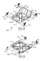
- FIG. 15 is a top-side perspective view of a support assembly for photovoltaic modules, according to yet another illustrative embodiment of the invention.
- FIG. 16 is a front elevational view of the support assembly of FIG. 15 ;
- FIG. 17 is a top plan view of the support assembly of FIG. 15 ;
- FIG. 18 is a side elevational view of the support assembly of FIG. 15 ;
- FIG. 19 is a bottom-side perspective view of the support assembly of FIG. 15 ;
- FIG. 20 is a bottom plan view of the support assembly of FIG. 15 ;
- FIG. 21 is a partially exploded perspective view of the support assembly of FIG. 15 , wherein one of the tubular members is exploded from the ballast tray in order to more clearly illustrate the manner in which the tubular member attaches to the ballast tray, and the manner in which the panel clamp member attaches to the tubular member;
- FIG. 22 is a top-side perspective view of a support assembly for photovoltaic modules, according to still another illustrative embodiment of the invention.
- FIG. 23 is a top plan view of the support assembly of FIG. 22 ;
- FIG. 24 is a bottom plan view of the support assembly of FIG. 22 ;
- FIG. 25 is a front elevational view of the support assembly of FIG. 22 ;
- FIG. 26 is a side elevational view of the support assembly of FIG. 22 ;
- FIG. 27 is a bottom-side perspective view of the support assembly of FIG. 22 ;
- FIG. 28 is a partially exploded perspective view of the support assembly of FIG. 22 , wherein one of the tubular members is exploded from the ballast tray in order to more clearly illustrate the manner in which the tubular member attaches to the ballast tray, and the manner in which the panel clamp member attaches to the tubular member;
- FIG. 29 is a top plan view of a photovoltaic module array, according to one illustrative embodiment of the invention, wherein the photovoltaic modules of the array are disposed in a landscape configuration and the photovoltaic modules are supported using a plurality of support assemblies, some of the support assemblies are tucked underneath the photovoltaic modules in the array, and the south row of the array comprises a plurality of connector tubes connecting support assemblies to one another in an east-west direction;
- FIG. 30 is a north side elevational view of the photovoltaic module array of FIG. 29 ;
- FIG. 31 is a top-side perspective view of the photovoltaic module array of FIG. 29 ;
- FIG. 32 is an east side elevational view of the photovoltaic module array of FIG. 29 ;
- FIG. 33 is another top-side perspective view of the photovoltaic module array of FIG. 29 ;
- FIG. 34 is a west side elevational view of the photovoltaic module array of FIG. 29 ;
- FIG. 35 is yet another top-side perspective view of the photovoltaic module array of FIG. 29 ;
- FIG. 36 is a bottom-side perspective view of the photovoltaic module array of FIG. 29 ;
- FIG. 37 is a bottom plan view of the photovoltaic module array of FIG. 29 ;
- FIG. 38 is another bottom-side perspective view of the photovoltaic module array of FIG. 29 , wherein the array is being viewed from a different angle than that of FIG. 36 ;
- FIG. 39 is a side elevational view of a panel clamp member of the support assemblies described herein, according to one illustrative embodiment of the invention.
- FIG. 40 is an end elevational view of the panel clamp member of FIG. 39 ;
- FIG. 41 is a first side perspective view of the panel clamp member of FIG. 39 ;
- FIG. 42 is a second side perspective view of the panel clamp member of FIG. 39 ;
- FIG. 43A is an enlarged perspective view of the serrations on the upstanding portion of the panel clamp member illustrated in the side perspective view of FIG. 43B (Detail “A”);
- FIG. 43B is another side perspective view of the panel clamp member of FIG. 39 ;
- FIG. 44 is yet another side perspective view of the panel clamp member of FIG. 39 ;
- FIG. 45 is a side perspective view of another panel clamp member of the support assemblies described herein, according to another illustrative embodiment of the invention, wherein the panel clamp member of FIG. 45 is additionally provided with a downwardly extending projection that is capable of resting on the upper surface of the panel clamp fastener;
- FIG. 46 is a perspective view of a tubular member of the support assembly depicted in the embodiment of FIGS. 22-28 ;
- FIG. 47 is a side elevational view of the tubular member of FIG. 46 ;
- FIG. 48A is an enlarged perspective view of the panel clamp slots on the end portion of the tubular member illustrated in the perspective view of FIG. 48B (Detail “B”);
- FIG. 48B is another perspective view of the tubular member of FIG. 46 ;
- FIG. 49 is a bottom plan view of the tubular member of FIG. 46 ;
- FIG. 50 is a top-side perspective view of a base clamp member of the support assembly depicted in the embodiment of FIGS. 64A-70B ;
- FIG. 51 is a bottom-side perspective view of the base clamp member of FIG. 50 ;
- FIG. 52 is a top plan view of the base clamp member of FIG. 50 ;
- FIG. 53 is a side elevational view of the base clamp member of FIG. 50 ;
- FIG. 54 is another top-side perspective view of the base clamp member of FIG. 50 ;
- FIG. 55 is another bottom-side perspective view of the base clamp member of FIG. 50 ;
- FIG. 56 is a perspective view illustrating the manner in which the support assembly depicted in the embodiment of FIGS. 22-28 is capable of being stacked with other such support assemblies;
- FIG. 57 is another perspective view of the stacked support assemblies illustrated in FIG. 56 ;
- FIG. 58 is an exploded side elevational view illustrating the nesting arrangement of the stacked support assemblies shown in FIGS. 56 and 57 ;
- FIG. 59 is an exploded perspective view illustrating the nesting arrangement of the stacked support assemblies shown in FIGS. 56 and 57 ;
- FIG. 60A is an enlarged perspective view of a portion of the photovoltaic module array of FIG. 60B , which illustrates the venting apertures in the wind deflector member (Detail “C”);
- FIG. 60B is a perspective view of a photovoltaic module array, according to another illustrative embodiment of the invention, wherein the photovoltaic modules of the array are disposed in a portrait configuration and the photovoltaic modules are supported using a plurality of support assemblies of the embodiment of FIGS. 22-28 ;
- FIG. 61A is an enlarged side perspective view of a portion of the photovoltaic module array of FIG. 61B , which illustrates the venting apertures in the wind deflector member and the attachment of the bottom edge of the wind deflector member to the base clamp member of the support assembly (Detail “D”);
- FIG. 61B is another perspective view of the photovoltaic module array of FIG. 60B ;
- FIG. 62A is an enlarged perspective view of a portion of the photovoltaic module array of FIG. 62B , which illustrates the angled wind deflector member disposed between the support assemblies (Detail “E”);
- FIG. 62B is a perspective view of a photovoltaic module array, according to yet another illustrative embodiment of the invention, wherein the photovoltaic modules of the array are disposed in a landscape configuration and the photovoltaic modules are supported using a plurality of support assemblies of the embodiment of FIGS. 22-28 ;
- FIG. 63 is a side elevational view of the photovoltaic module array of FIG. 62B ;
- FIG. 64A is an enlarged perspective view of a portion of the support assembly of FIG. 64B , which illustrates the wire management feature of the ballast tray (Detail “F”);
- FIG. 64B is a top-side perspective view of a support assembly for photovoltaic modules, according to yet another illustrative embodiment of the invention, which is similar to the embodiment of FIGS. 15-21 , except that the support assembly is provided with a slightly different ballast tray;
- FIG. 65 is a top plan view of the support assembly of FIG. 64B ;
- FIG. 66 is a front elevational view of the support assembly of FIG. 64B ;
- FIG. 67 is a partially exploded perspective view of the support assembly of FIG. 64B , wherein one of the tubular members is exploded from the ballast tray in order to more clearly illustrate the manner in which the tubular member attaches to the ballast tray, and the manner in which the panel clamp member attaches to the tubular member;
- FIG. 68 is a bottom plan view of the support assembly of FIG. 64B ;
- FIG. 69 is a side elevational view of the support assembly of FIG. 64B ;
- FIG. 70A is an enlarged perspective view of a portion of the support assembly of FIG. 70B , which illustrates the drainage holes in the bottom of the ballast tray (Detail “G”);
- FIG. 70B is a bottom perspective view of the support assembly of FIG. 64B ;
- FIG. 71 is a top-side perspective view of a photovoltaic module array, according to yet another illustrative embodiment of the invention, which is similar to the embodiment of FIGS. 29-38 , except that some of connector tubes connecting the support assemblies to one another in an east-west direction are attached to the roof using roof mounts;
- FIG. 72A is an enlarged perspective view of a portion of the photovoltaic module array of FIG. 72B , which illustrates the roof mount used to secure one of the east-west connector tubes to the roof (Detail “H”);
- FIG. 72B is another perspective view of the photovoltaic module array of FIG. 71 ;
- FIG. 73 is a top-side perspective view of a support assembly for photovoltaic modules, according to yet another illustrative embodiment of the invention.
- FIG. 74 is a bottom-side perspective view of the support assembly of FIG. 73 ;
- FIG. 75 is a top plan view of the support assembly of FIG. 73 ;
- FIG. 76 is a front elevational view of the support assembly of FIG. 73 ;
- FIG. 77 is a partially exploded perspective view of the support assembly of FIG. 73 , wherein the tubular members are exploded from the channel members in order to more clearly illustrate the manner in which the tubular members attach to the channel members, and the manner in which the panel clamp members attach to the tubular members;
- FIG. 78 is a side elevational view of the partially exploded support assembly of FIG. 77 ;
- FIG. 79 is a side elevational view of the support assembly of FIG. 73 ;
- FIG. 80A is a top-side perspective view of a photovoltaic module array, according to still another illustrative embodiment of the invention, wherein the photovoltaic modules of the array are disposed in a landscape configuration and the photovoltaic modules are supported using a plurality of support assemblies, and wherein some of the support assemblies are tucked underneath the photovoltaic modules in the array;
- FIG. 80B is an enlarged perspective view of a corner of a wind deflector in the photovoltaic module array of FIG. 80A , which illustrates the venting apertures in the wind deflector member and the securement of the wind deflector to the panel clamp (Detail “I”);
- FIG. 81A is an enlarged perspective view of a wind deflector bracket in the photovoltaic module array of FIG. 81B , which illustrates the securement of the wind deflector to the wind deflector bracket (Detail “J”);
- FIG. 81B is a bottom-side perspective view of the photovoltaic module array of FIG. 80A , wherein the photovoltaic module array is oriented in a south-facing manner;
- FIG. 82 is another top-side perspective view of the photovoltaic module array of FIG. 80A , wherein the photovoltaic module array is oriented in a south-facing manner;
- FIG. 83 is another top-side perspective view of the photovoltaic module array of FIG. 80A , wherein the photovoltaic module array is oriented in a north-facing manner;
- FIG. 84 is a front elevational view of the photovoltaic module array of FIG. 80A , wherein the photovoltaic module array is oriented in a north-facing manner;
- FIG. 85 is a side view of the wind deflector bracket illustrated in FIG. 81A ;
- FIG. 86 is a perspective view of the wind deflector bracket illustrated in FIG. 81A ;
- FIG. 87A is a bottom perspective view of the photovoltaic module array of FIG. 80A ;
- FIG. 87B is an enlarged rear perspective view of a wind deflector bracket and channel member in the photovoltaic module array of FIG. 87A , which illustrates the manner in which the wind deflector bracket is attached to the channel member (Detail “K”);
- FIG. 88A is another top-side perspective view of the photovoltaic module array of FIG. 80A , wherein several wind deflectors have been removed to better illustrate the tucked support assemblies and the wind deflector bracket;
- FIG. 88B is an enlarged frontal perspective view of a wind deflector bracket and channel member in the photovoltaic module array of FIG. 88A , which illustrates the manner in which the wind deflector bracket is attached to the channel member (Detail “L”);
- FIG. 89 is a top-side perspective view of a base clamp member of the support assembly depicted in the embodiment of FIGS. 73-79 ;
- FIG. 90A is a side perspective view of a panel clamp member of the support assembly depicted in the embodiment of FIGS. 73-79 ;
- FIG. 90B is an enlarged perspective view of the protrusion on the semi-circular tube receiving portion of the panel clamp member illustrated in the side perspective view of FIG. 90A (Detail “M”).
- the support assembly 100 generally includes a ballast tray 10 configured to accommodate one or more ballasts (e.g., ballasts 68 —see FIG. 31 ); a pair of spaced-apart tubular members 20 , 22 coupled to the ballast tray 10 , the tubular members 20 , 22 configured to support one or more photovoltaic modules 66 above a support surface (see FIG. 31 ); and one or more panel clamp members 40 coupled to the tubular members 20 , 22 . As best shown in FIGS.
- the one or more panel clamp members 40 of the illustrative embodiment include a looped end portion 44 for receiving an edge portion of a photovoltaic module frame, and an upstanding portion 46 configured to be disposed proximate to a side surface of the photovoltaic module frame when the one or more panel clamp members 40 are engaged with the photovoltaic module frame.
- the ballast tray 10 of the illustrative support assembly 100 will be described.
- the ballast tray or ballast pan 10 is provided with radiused edges configured to prevent damage to the support surface (e.g, the roof) on which the support assembly 100 is installed.
- the radiused edges of the ballast tray 10 help to prevent the ballast tray 10 from puncturing or otherwise damaging the roof membrane.
- the ballast tray 10 is provided with a stamped pattern 12 formed therein for increasing a structural rigidity of the ballast tray 10 .
- the stamped pattern 12 of the ballast tray 10 comprises four (4) elongated recesses arranged in an X-pattern, and two (2) circular recesses provided on north and south sides of the X-pattern of elongated recesses.
- the ballast tray 10 is provided with a plurality of drainage apertures 16 formed therethrough configured to drain water from the ballast tray 10 (e.g., the drainage apertures 16 may be formed in the bottoms on the stamped recesses).
- the ballast tray 10 of the support assembly 100 is configured to contain fragmented portions of the one or more ballasts (e.g., ballasts 68 —see FIG.
- the ballast tray 10 of the illustrated embodiment is provided with an upturned lip 14 on the north and south edges thereof (e.g., see FIG. 1 ), and is provided with upturned east and west side portions 18 (e.g., see FIGS. 1 and 6 ).
- the middle portion 20 c , 22 c of each tubular member 20 , 22 is received within a respective channel disposed adjacent to a respective ones of the upturned side portions 18 .
- the pair of tubular members 20 , 22 are spaced apart from one another across the ballast tray 10 .
- the first tubular member 20 has a first bent end portion 20 a for supporting a photovoltaic module at a first elevation, a second bent end portion 20 b for supporting a photovoltaic module at a second elevation that is higher than the first elevation relative to the support surface (e.g., the roof), and a middle portion 20 c that connects the first and second end portions 20 a , 20 b to one another.
- the second tubular member 22 has a first bent end portion 22 a for supporting a photovoltaic module at a first elevation, a second bent end portion 22 b for supporting a photovoltaic module at a second elevation that is higher than the first elevation relative to the support surface (e.g., the roof), and a middle portion 22 c that connects the first and second end portions 22 a , 22 b to one another.
- the support surface e.g., the roof
- the longitudinal axes of the middle portions 20 c , 22 c of the tubular members 20 , 22 generally extend in the north-south direction of the support assembly 100 , but the longitudinal axes of the bent end portions 20 a , 20 b , 22 a , 22 b point in the east-west direction of the support assembly 100 (i.e., the bent end portions 20 a , 20 b , 22 a , 22 b are generally transversely oriented relative to the middle portions 20 c , 22 c of the tubular members 20 , 22 ). Also, as depicted in FIGS.
- the bent end portions 20 a , 20 b of the first tubular member 20 and the bent end portions 22 a , 22 b of the second tubular member 22 each comprises a plurality of spaced-apart slots 24 formed in the bent end portions 20 a , 20 b , 22 a , 22 b of the first and second tubular members 20 , 22 .
- the spaced-apart slots 24 serve as visual and tactile indicia for representing a plurality of predetermined mounting locations for the panel clamp members 40 .
- Each of the spaced-apart slots 24 is indicative of a respective predetermined mounting location for a panel clamp member 40 .
- each panel clamp member 40 comprises a slot alignment tab member 48 that engages with one of the slots 24 in the tubular members 20 , 22 .
- the engagement between the slot 24 in the tubular member 20 , 22 and the tab member 48 of the panel clamp member 40 limits a rotation of the panel clamp member 40 on the tubular member 20 , 22 so as to facilitate ease of installation of the photovoltaic modules 66 .
- the tubular members 20 , 22 may be provided with tab members and the panel clamp members 40 may be provided with slots that engage with respective ones of the tab members of the tubular members 20 , 22 .
- the engagement between the tab member of the tubular member 20 , 22 and the slot of the panel clamp member 40 limits a rotation of the panel clamp member 40 on the tubular member 20 , 22 so as to facilitate ease of installation of the photovoltaic modules 66 .
- the tubular members 20 , 22 of the support assembly 100 comprise an internal cavity disposed therein (i.e., a central internal cavity).
- the tubular members 20 , 22 may comprise a ballasting material disposed in the internal cavity thereof for ballasting the plurality of photovoltaic modules 66 on the support surface (e.g., on the roof).
- the ballasting material in the internal cavities of the tubular members 20 , 22 may be provided in addition to, or instead of the ballasts 68 described above.
- the ballasting material may comprise sand or gravel, or a combination of both sand and gravel.
- the tubular members 20 , 22 may be prefilled with the ballasting material prior to being installed in place on the support surface (e.g., prior to being installed in place on the roof).
- each of the tubular members 20 , 22 of the support assembly 100 is coupled to the ballast tray 10 of support assembly 100 by means of base clamp members 30 .
- each of the tubular members 20 , 22 is secured to the ballast tray 10 by a pair of spaced-apart base clamp members 30 connected to the tubular member middle portions 20 c , 22 c .
- the middle portion 20 c , 22 c of each tubular member 20 , 22 comprises a pair of spaced-apart base clamp slots 26 that correspond to respective ones of the base clamp members 30 .
- Each base clamp member 30 may comprise a tab member that corresponds to one of the slots 26 in the tubular members 20 , 22 so that an engagement between the slot 26 and the tab member allows the tubular member 20 , 22 to be rotatably converted from a shipping position to a mounting position.
- the middle portions 20 c , 22 c of the tubular members 20 , 22 may be provided with tab members and the base clamp members 30 may be provided with slots that engage with respective ones of the tab members of the tubular members 20 , 22 .
- the engagement between the tab member of the tubular member 20 , 22 and the slot of the base clamp member 30 allows the tubular member 20 , 22 to be rotatably converted from a shipping position to a mounting position.
- each bent end portion 20 a , 20 b of the first tubular member 20 comprises a respective panel clamp member 40
- each bent end portion 22 a , 22 b of the second tubular member 22 comprises a respective panel clamp member 40 .
- the panel clamp members 40 that are attached to the bent end portions 20 b , 22 b are disposed at higher elevations than the panel clamp members 40 that are attached to the bent end portions 20 a , 22 a so that the photovoltaic modules 66 are supported at angled orientations in the photovoltaic array (e.g., as shown in FIG. 31 , the south edge of each photovoltaic module 66 , which is supported by lower bent end portions 20 a , 22 a , is disposed at a lower elevation than the north edge of each photovoltaic module 66 , which is supported by higher bent end portions 20 b , 22 b.
- each of the panel clamp members 40 of the illustrative embodiment include a looped end portion 44 for receiving an edge portion of a photovoltaic module frame, and an upstanding portion 46 configured to be disposed proximate to a side surface of the photovoltaic module frame when the panel clamp member 40 is engaged with the photovoltaic module frame. As best shown in FIG.
- the looped end portion 44 of the panel clamp member 40 forms a panel edge slot 45 for receiving an edge portion of a photovoltaic module frame
- the middle portion of the panel clamp member 40 comprises a generally horizontal landing surface for a bottom surface of the photovoltaic module frame at the opening to the panel edge slot 45 (see FIG. 44 ) so as to facilitate the engagement of the panel clamp member 40 with the photovoltaic module frame.
- FIGS. 41, 42, and 44 it can be seen that the looped end portion 44 of the panel clamp member 40 is oppositely disposed with respect to the upstanding portion 46 , and that the looped end portion 44 is connected to the upstanding portion 46 by the semi-circular tube receiving portion 41 of the panel clamp member 40 .
- the semi-circular tube receiving portion 41 of the panel clamp member 40 partially circumscribes the tubular member 20 , 22 .
- the tube receiving portion 41 , the looped end portion 44 , and the upstanding portion 46 are each part of the single body portion of the panel clamp member 40 (e.g., the panel clamp member 40 may be formed from a single piece of metal).
- the panel clamp member 40 is provided with a fastener member 42 (e.g., a threaded bolt or screw) that secures the single body portion of the panel clamp member 40 to the photovoltaic module frame.
- the panel clamp member 40 When the fastener member 42 of the panel clamp member 40 is tightened, the panel clamp member 40 is configured to deform the wall of the tubular member 20 , 22 to which it is secured so as to resist a rotation of the panel clamp member 40 about the tubular member 20 , 22 . As shown in FIGS. 39, 41, and 44 , the fastener member 42 of the panel clamp member 40 passes through an elongated slot in the upstanding portion 46 and a threaded aperture beneath the looped end portion 44 .
- the panel clamp member 40 is selectively positionable along a length of the tubular member 20 , 22 so as to enable a user to select a particular mounting location on photovoltaic module frame for the panel clamp member 40 (e.g., as explained above, the tab member 48 of the panel clamp member 40 can be engaged with a selected one of the elongate panel clamp slots 24 in the bent end portion 20 a , 20 b , 22 a , 22 b of the tubular member 20 , 22 ).
- the panel clamp member 40 is rotatable relative to the tubular member 20 , 22 prior to the panel clamp member 40 being secured to the photovoltaic module frame so as to allow the support assembly 100 to accommodate undulations (e.g., north-south undulations) and uneven regions of the support surface (e.g., the roof on which the photovoltaic array is mounted).
- undulations e.g., north-south undulations
- uneven regions of the support surface e.g., the roof on which the photovoltaic array is mounted.
- the upstanding portion 46 of the panel clamp member 40 which is configured to be disposed proximate to a side surface of the photovoltaic module frame when the panel clamp member 40 is engaged with the photovoltaic module frame, comprises parallel edge portions with a plurality of serrations 47 spaced apart along the lengths of each panel clamp edge portion.
- the serrations 47 on each serrated edge portion of the panel clamp member 40 are configured to provide integrated grounding for one or more photovoltaic modules 66 .
- the serrations 47 on each serrated edge portion are further configured to resist an uplift of the one or more photovoltaic modules resulting from wind forces acting on the one or more photovoltaic modules 66 .
- FIG. 45 An alternative embodiment of the panel clamp member is depicted in FIG. 45 .
- the panel clamp member 40 ′ of FIG. 45 is similar in many respects to the aforedescribed panel clamp member 40 of FIGS. 41-44 . That is, like the panel clamp member 40 , the panel clamp member 40 ′ of FIG. 45 includes a fastener member 42 ′, a looped end portion 44 ′, an upstanding portion 46 with serrations 47 , and a tab member 48 . Although, unlike the panel clamp member 40 , the panel clamp member 40 ′ of FIG. 45 further includes a downwardly extending projection or leg 43 .
- the downwardly extending leg 43 of the panel clamp member 40 ′ is capable of being disposed against an upper surface of the fastener member 42 ′ (see FIG. 45 ) when the panel clamp member 40 ′ is engaged with the photovoltaic module frame so that the downwardly extending leg 43 is able to reduce stresses imparted on a middle portion of the panel clamp member 40 ′ by supporting a portion of the weight of the photovoltaic module 66 on the fastener member 42 ′.
- FIGS. 7-14 Another illustrative embodiment of a support assembly for supporting one or more photovoltaic modules on a support surface (e.g., a roof) is seen generally at 200 in FIGS. 7-14 .
- a support surface e.g., a roof
- FIGS. 7-14 Another illustrative embodiment of a support assembly for supporting one or more photovoltaic modules on a support surface (e.g., a roof) is seen generally at 200 in FIGS. 7-14 .
- FIGS. 7-14 is similar to that of the embodiment of FIGS. 1-6 .
- many elements are common to both such embodiments.
- the elements that the embodiment of the support assembly of FIGS. 7-14 has in common with the embodiment of FIGS. 1-6 will not be discussed because these components have already been explained in detail above.
- these elements are denoted using the same reference characters that were used in the embodiment of FIGS. 1-6 .
- the support assembly 200 of FIGS. 7-14 generally includes a ballast tray 10 ′ configured to accommodate one or more ballasts (e.g., ballasts 68 —see FIG. 31 ); a pair of spaced-apart tubular members 50 , 52 coupled to the ballast tray 10 ′, each of the spaced-apart tubular members 50 , 52 configured to support one or more photovoltaic modules 66 above a support surface (see FIG. 31 ), and a plurality of panel clamp members 40 coupled to the tubular members 50 , 52 . As shown in FIG.
- a first pair of panel clamp members 40 is coupled to a first one 50 of the pair of spaced-apart tubular members 50 , 52
- a second pair of panel clamp members 40 is coupled to a second one 52 of the pair of spaced-apart tubular members 50 , 52
- Each of the panel clamp members 40 is configured to secure a respective photovoltaic module frame of the one or more photovoltaic modules 66 to the support assembly 200 .
- each of the spaced-apart tubular members 50 , 52 of the support assembly 200 extends in a generally east-west direction of the one or more photovoltaic modules 66 , rather than in a north-south direction, as described above for the embodiment of FIGS. 1-6 .
- each of the tubular members 50 , 52 of the support assembly 200 is generally linear in shape (e.g., each of the tubular members 50 , 52 has a straight pipe configuration).
- the first and second tubular members 50 , 52 are identical in form so that a single tube part can be interchangeably used for the both the first and second tubular members 50 , 52 , thereby reducing the part costs of the support assembly 200 by obviating the need for different tubes to be formed for each of the first and second tubular members 50 , 52 .
- the support assembly 200 comprises a high-side connector member 60 for elevating the second tubular member 52 above the ballast tray 10 ′ so that the second tubular member 52 is disposed at a higher elevation relative to the support surface (e.g., the roof) as compared to the first tubular member 50 .
- the high-side connector member 60 also advantageously operates as a wind deflector configured to deflect wind up and over one or more photovoltaic modules 66 in an array rather than under the one or more photovoltaic modules 66 .
- the tubular members 50 , 52 of the support assembly 200 are coupled to the ballast tray 10 ′ by means of base clamp members 30 ′.
- the low-side tubular member 50 is secured to front end of the ballast tray 10 ′ by a pair of spaced-apart base clamp members 30 ′, while the high-side tubular member 52 is secured to the upper edge portion of the high-side connector member 60 by a pair of spaced-apart base clamp members 30 ′.
- the low-side tubular member 50 is received within tube receiving channel 13 .
- the bottom of the ballast tray 10 ′ is provided with a plurality of ballast tray feet 11 for resting against the support surface (e.g., roof) on which the ballast tray 10 ′ is disposed.
- the ballast tray 10 ′ of the embodiment of FIGS. 7-14 is provided with an upturned lip 14 ′ on the east and west edges thereof (e.g., see FIGS. 12 and 13 ), and is provided with upturned side portions 18 ′ on the north and south sides thereof (e.g., see FIGS. 8, 11, 13, and 14 ).
- the low-side tubular member 50 is received within the tube receiving channel 13 disposed adjacent to the north upturned side portion 18 ′ of the ballast tray 10 ′.
- FIGS. 15-21 Yet another illustrative embodiment of a support assembly for supporting one or more photovoltaic modules on a support surface (e.g., a roof) is seen generally at 300 in FIGS. 15-21 .
- a support surface e.g., a roof
- FIGS. 15-21 is similar to that of the embodiment of FIGS. 1-6 and the embodiment of FIGS. 7-14 .
- many elements are common to all of these embodiments.
- the elements that the embodiment of the support assembly of FIGS. 15-21 has in common with the embodiments of FIGS. 1-6 and 7-14 will not be discussed because these components have already been explained in detail above.
- these elements are denoted using the same reference characters that were used in the embodiments of FIGS. 1-6 and 7-14 .
- the support assembly 300 of FIGS. 15-21 generally includes a ballast tray 10 ′′ configured to accommodate one or more ballasts (e.g., ballasts 68 —see FIG. 31 ); a pair of spaced-apart tubular members 50 , 54 coupled to the ballast tray 10 ′′, each of the spaced-apart tubular members 50 , 54 configured to support one or more photovoltaic modules 66 above a support surface (see FIG. 31 ), and a plurality of panel clamp members 40 coupled to the tubular members 50 , 54 . As shown in FIG.
- a first pair of panel clamp members 40 is coupled to a first one 50 of the pair of spaced-apart tubular members 50 , 54
- a second pair of panel clamp members 40 is coupled to a second one 54 of the pair of spaced-apart tubular members 50 , 54
- Each of the panel clamp members 40 is configured to secure a respective photovoltaic module frame of the one or more photovoltaic modules 66 to the support assembly 300 .
- the tubular members 50 , 54 extend in a generally east-west direction of the one or more photovoltaic modules 66 .
- the second tubular member 54 of the support assembly 300 in FIGS. 15-21 has a different configuration than the first tubular member 50 .
- the low-side tubular member 50 of the support assembly 300 is generally linear in shape (i.e., the low-side tubular member 50 has a straight pipe configuration).
- the high-side tubular member 54 of the support assembly 300 is not linear in shape. Rather, as shown in FIGS.
- the high-side tubular member 54 has oppositely disposed bent end portions 54 a , 54 b and a generally straight middle portion 54 c . As shown in these figures, the bent end portions 54 a , 54 b of the high-side tubular member 54 are disposed at a higher elevation relative to the support surface (e.g., relative to the roof) as compared to the low-side tubular member 50 .
- the high-side tubular member 54 with upturned end portions 54 a , 54 b is used in place of the high-side connector member 60 described in conjunction with the support assembly 200 .
- the tubular members 50 , 54 of the support assembly 300 are coupled to the ballast tray 10 ′′ by means of base clamp members 30 ′′.
- base clamp members 30 ′′ are coupled to the ballast tray 10 ′′ by means of base clamp members 30 ′′.
- the low-side tubular member 50 is secured to the front end of the ballast tray 10 ′′ by a pair of spaced-apart base clamp members 30 ′′, while the generally straight middle portion 54 c of the high-side tubular member 54 is secured to the rear end of the ballast tray 10 ′′ by a pair of spaced-apart base clamp members 30 ′′.
- the ballast tray 10 ′′ of the support assembly 300 has a different configuration than the ballast trays 10 , 10 ′ described above.
- the ballast tray 10 ′′ is provided with an upturned lip disposed around the periphery thereof for containing the one or more ballasts 68 therein.
- FIGS. 64A-70B Still another illustrative embodiment of a support assembly for supporting one or more photovoltaic modules on a support surface (e.g., a roof) is seen generally at 300 ′ in FIGS. 64A-70B .
- a support surface e.g., a roof
- FIGS. 64A-70B is similar to that of the embodiment of FIGS. 15-21 described above.
- many elements are common to both of these embodiments.
- the elements that the embodiment of the support assembly of FIGS. 64A-70B has in common with the embodiment of FIGS. 15-21 will not be discussed because these components have already been explained in detail above.
- these elements are denoted using the same reference characters that were used in the embodiment of FIGS. 15-21 .
- the support assembly 300 ′ of FIGS. 64A-70B generally includes a ballast tray 10 ′′′′ configured to accommodate one or more ballasts (e.g., ballasts 68 —see FIG. 31 ); a pair of spaced-apart tubular members 50 , 54 coupled to the ballast tray 10 ′′′′, each of the spaced-apart tubular members 50 , 54 configured to support one or more photovoltaic modules 66 above a support surface (see FIG. 31 ), and a plurality of panel clamp members 40 coupled to the tubular members 50 , 54 . As shown in FIG.
- a first pair of panel clamp members 40 is coupled to a first one 50 of the pair of spaced-apart tubular members 50 , 54
- a second pair of panel clamp members 40 is coupled to a second one 54 of the pair of spaced-apart tubular members 50 , 54
- Each of the panel clamp members 40 is configured to secure a respective photovoltaic module frame of the one or more photovoltaic modules 66 to the support assembly 300 ′.
- the tubular members 50 , 54 of the support assembly 300 ′ also extend in a generally east-west direction of the one or more photovoltaic modules 66 .
- the ballast tray 10 ′′′′ of the support assembly 300 ′ differs slightly from the ballast tray 10 ′′ of the support assembly 300 explained above.
- the ballast tray 10 ′′′′ comprises a plurality of spaced-apart gussets 17 disposed along the north and south sides of the ballast tray 10 ′′′′.
- the gussets 17 reinforce the ballast tray 10 ′′′′ so as to increase its structural integrity and rigidity. Further, as best illustrated in FIGS.
- the ballast tray 10 ′′′′ is provided with a plurality of drainage apertures 15 , 16 ′ formed therethrough configured to drain water from the ballast tray 10 ′′′′.
- the drainage apertures 15 are disposed in the corners of the ballast tray 10 ′′′′ (see Detail “G” in FIG. 70A ), while the drainage apertures 16 ′ are disposed between the corner drainage apertures 15 along the north and south sides of the ballast tray 10 ′′′′. Also, as depicted in FIGS.
- the east and west edges of the ballast tray 10 ′′′′ are provided with pairs of spaced-apart wire management clips 19 for accommodating one or more electrical wires of the plurality of photovoltaic modules 66 in the array.
- the tubular members 50 , 54 of the support assembly 300 ′ are coupled to the ballast tray 10 ′′′′ by means of base clamp members 30 ′′′.
- the low-side tubular member 50 is secured to the front end of the ballast tray 10 ′′′′ by a pair of spaced-apart base clamp members 30 ′′′, while the generally straight middle portion 54 c of the high-side tubular member 54 is secured to the rear end of the ballast tray 10 ′′′′ by a pair of spaced-apart base clamp members 30 ′′′.
- FIGS. 50-55 The details of the illustrative base clamp members 30 ′′′ are shown in FIGS. 50-55 .
- the base clamp member 30 ′′′ is provided with a threaded fastener member 34 (e.g., a threaded bolt or screw) and an associated nut 32 for securing the base clamp member 30 ′′′ to the ballast tray 10 ′′′′.
- a threaded fastener member 34 e.g., a threaded bolt or screw
- the threaded fastener member 34 passes through the square-shaped lower fastener aperture 36 in the bottom of the base clamp member 30 ′′′ and a circular upper fastener aperture 37 disposed above the lower fastener aperture 36 .
- the square-shaped lower fastener aperture 36 accommodates the square cross-section of the threaded fastener member 34 near the fastener head, while the circular upper fastener aperture 37 accommodates the circular cross-section of the shaft of the threaded fastener member 34 .
- the base clamp member 30 ′′′ also includes tab members 35 disposed on the top thereof for receiving the bottom edge of a wind deflector 70 (see Detail “D” in FIG. 61A ). The details of the wind deflectors 70 will be described in more detail hereinafter.
- FIGS. 22-28 Yet another illustrative embodiment of a support assembly for supporting one or more photovoltaic modules on a support surface (e.g., a roof) is seen generally at 400 in FIGS. 22-28 .
- the illustrative embodiment of FIGS. 22-28 is similar to the aforedescribed embodiments of the support assemblies 100 , 200 , 300 , and 300 ′.
- many elements are common to all of these embodiments.
- the elements that the embodiment of the support assembly of FIGS. 22-28 has in common with the aforedescribed embodiments will not be discussed because these components have already been explained in detail above.
- these elements are denoted using the same reference characters that were used in the embodiments of FIGS. 1-6, 7-14, 15-21, and 64A-70B .
- the support assembly 400 of FIGS. 22-28 generally includes a ballast tray 10 ′′′ configured to accommodate one or more ballasts (e.g., ballasts 68 —see FIG. 31 ); a pair of spaced-apart tubular members 56 , 58 coupled to the ballast tray 10 ′′′, each of the spaced-apart tubular members 56 , 58 configured to support one or more photovoltaic modules 66 above a support surface (see FIG. 31 ), and a plurality of panel clamp members 40 coupled to the tubular members 56 , 58 . As shown in FIG.
- a first pair of panel clamp members 40 is coupled to a first one 56 of the pair of spaced-apart tubular members 56 , 58
- a second pair of panel clamp members 40 is coupled to a second one 58 of the pair of spaced-apart tubular members 56 , 58
- Each of the panel clamp members 40 is configured to secure a respective photovoltaic module frame of the one or more photovoltaic modules 66 to the support assembly 400 .
- the tubular members 56 , 58 extend in a generally north-south direction of the one or more photovoltaic modules 66 .
- FIGS. 22 and 28 it can be seen that the ballast tray 10 ′′′ of the support assembly 400 is provided with upturned front and rear sides 18 ′′ in order to contain the one or more ballasts 68 therein.
- the tubular members 56 , 58 of the support assembly 400 have a different configuration than the tubular members 20 , 22 , 50 , 52 , 54 described above in conjunction with the preceding embodiments.
- the first tubular member 56 has a first bent end portion 56 a for supporting a photovoltaic module at a first elevation, a second bent end portion 56 b for supporting a photovoltaic module at a second elevation that is higher than the first elevation relative to the support surface (e.g., the roof), and a straight middle portion 56 c and an inclined middle portion 56 d that connects the first and second end portions 56 a , 56 b to one another.
- the support surface e.g., the roof
- the second tubular member 58 has a first bent end portion 58 a for supporting a photovoltaic module at a first elevation, a second bent end portion 58 b for supporting a photovoltaic module at a second elevation that is higher than the first elevation relative to the support surface (e.g., the roof), and a straight middle portion 58 c and an inclined middle portion 58 d that connects the first and second end portions 58 a , 58 b to one another.
- the support surface e.g., the roof
- the longitudinal axes of the middle portions 56 c , 56 d , 58 c , 58 d of the tubular members 56 , 58 generally extend in the north-south direction of the support assembly 400 , but the longitudinal axes of the bent end portions 56 a , 56 b , 58 a , 58 b point in the east-west direction of the support assembly 400 (i.e., the bent end portions 56 a , 56 b , 58 a , 58 b are generally transversely oriented relative to the middle portions 56 c , 56 d , 58 c , 58 d of the tubular members 56 , 58 ). Also, as depicted in FIGS.
- the bent end portions 56 a , 56 b of the first tubular member 56 and the bent end portions 58 a , 58 b of the second tubular member 58 each comprises a plurality of spaced-apart slots 24 formed in the bent end portions 56 a , 56 b , 58 a , 58 b of the first and second tubular members 56 , 58 .
- the spaced-apart slots 24 serve as visual and tactile indicia for representing a plurality of predetermined mounting locations for the panel clamp members 40 .
- Each of the spaced-apart slots 24 is indicative of a respective predetermined mounting location for a panel clamp member 40 .
- each panel clamp member 40 engages with a respective one of the slots 24 in the tubular members 56 , 58 .
- the engagement between the slot 24 in the tubular member 56 , 58 and the tab member 48 of the panel clamp member 40 limits a rotation of the panel clamp member 40 on the tubular member 56 , 58 so as to facilitate ease of installation of the photovoltaic modules 66 .
- the first and second tubular members 56 , 58 are identical in form so that a single tube part can be interchangeably used for the both the first and second tubular members 56 , 58 , thereby reducing the part costs of the support assembly 400 by obviating the need for different tubes to be formed for each of the first and second tubular members 56 , 58 .
- each tubular member 56 , 58 of the support assembly 400 is supported by a support bracket 62 .
- the upper end of each support bracket 62 is received within a slot 25 disposed in the underside of each tubular member 56 , 58 (refer to FIGS. 48B and 49 ).
- the oppositely-disposed lower end of each support bracket is secured to the upturned rear side 18 ′′ by a fastener 64 (e.g., a threaded bolt or screw—see FIG. 28 ).
- a fastener 64 e.g., a threaded bolt or screw—see FIG. 28 .
- the support brackets 62 elevate the second bent end portions 56 b , 58 b of the tubular members 56 , 58 a predetermined distance above the support surface (e.g., the roof) on which the photovoltaic array is installed.
- each of the tubular members 56 , 58 of the support assembly 400 may be configured to be rotatably converted from a shipping position to a mounting position.
- the support assemblies 400 are configured to nest with one another so that compact stacked arrangements 410 of support assemblies 400 may be formed, thereby minimizing the shipping size of the support assemblies 400 (see FIG. 56 ).
- the stacked shipping arrangement 410 of the nested support assemblies 400 enables the shipping and handling costs associated with transporting the support assemblies 400 to be lowered.
- the compact stacked arrangements 410 of support assemblies 400 can be shipped using standard pallet sizes, thereby obviating the need for specialized shipping pallets.
- the support assemblies 100 , 300 , 300 ′ described above are also capable of nesting with one another so that compact stacked arrangements of the support assemblies 100 , 300 , 300 ′ may be formed.
- tubular members 56 , 58 of the support assemblies 400 are convertible between shipping and mounting positions, the tubular members 56 , 58 are able to be furnished to the installer preassembled on the ballast tray 10 ′′′, thereby reducing the installation time necessary to install the photovoltaic array on the support surface (e.g., on the roof).
- each of the panel clamp members 40 is preassembled on the tubular members 56 , 58 of the support assemblies 400 to further reduce the requisite installation time.
- tubular members 56 , 58 when the tubular members 56 , 58 are in their mounting positions, rotational movement of the tubular members 56 , 58 relative to their base clamp members 30 ′′ is restricted to a predetermined angular range so as to enhance an installation speed of the support assembly 400 .
- the rotational adjustability of the tubular members 56 , 58 relative to their base clamp members 30 ′′ also enables undulations of the support surface (e.g., of the roof) in a generally east-west direction to be accommodated.
- FIGS. 73-79 Yet another illustrative embodiment of a support assembly for supporting one or more photovoltaic modules on a support surface (e.g., a roof) is seen generally at 420 in FIGS. 73-79 .
- a support surface e.g., a roof
- FIGS. 73-79 is similar to that of the embodiment of FIGS. 7-14 .
- some elements are similar between the two embodiments.
- the elements that the embodiment of the support assembly of FIGS. 73-79 has in common with the embodiment of FIGS. 7-14 will not be discussed in detail because these components have already been explained in detail above.
- these elements are denoted using reference characters that are similar to those used in the embodiment of FIGS. 7-14 .
- the support assembly 420 of FIGS. 73-79 generally includes a ballast tray 90 configured to accommodate one or more ballasts (e.g., ballasts 68 —see FIG. 80A ); a pair of spaced-apart tubular members 50 ′, 52 ′, each of the spaced-apart tubular members 50 ′, 52 ′ configured to support one or more photovoltaic modules 66 above a support surface (see FIG. 80A ), and a plurality of panel clamp members 40 ′′ coupled to the tubular members 50 ′, 52 ′. As shown in FIG.
- ballasts e.g., ballasts 68 —see FIG. 80A
- a pair of spaced-apart tubular members 50 ′, 52 ′ each of the spaced-apart tubular members 50 ′, 52 ′ configured to support one or more photovoltaic modules 66 above a support surface (see FIG. 80A ), and a plurality of panel clamp members 40 ′′ coupled to the tubular members 50 ′
- a first pair of panel clamp members 40 ′′ is coupled to a first one 50 ′ of the pair of spaced-apart tubular members 50 ′, 52 ′, and a second pair of panel clamp members 40 ′′ is coupled to a second one 52 ′ of the pair of spaced-apart tubular members 50 ′, 52 ′.
- Each of the panel clamp members 40 ′′ is configured to secure a respective photovoltaic module frame of the one or more photovoltaic modules 66 to the support assembly 420 .
- each of the spaced-apart tubular members 50 ′, 52 ′ of the support assembly 420 is connected to a pair of spaced-apart channel members 96 by base clamp members 30 ′′′′.
- each of the channel members 96 longitudinally extends in a generally north-south direction.
- each of the channel members 96 has a curved first end 96 a for receiving a bottom portion of the tubular member 50 ′ disposed at the lower elevation and a curved second end 96 b for receiving a bottom portion of the tubular member 52 ′ disposed at the higher elevation.
- the ends 96 a , 96 b of each channel member 96 are provided with a generally L-shaped slot 97 formed therein for receiving a fastener of a respective base clamp member 30 ′′′′.
- each of the channel members 96 is generally L-shaped with curved corners so as to prevent damage to the support surface (e.g., the roof surface). Also, as shown in FIGS. 73, 78, and 79 , the upstanding portion of each channel member 96 , which supports the tubular member 52 ′ disposed at the higher elevation, is provided with a pair of spaced-apart slots 98 disposed in one side thereof for receiving hook members 108 of a wind deflector bracket member 102 (as will be described in more detail hereinafter).
- the U-shaped cross-section of each channel member 96 increases the strength and rigidity of the channel member 96 . Also, the U-shaped cross-section of each channel member 96 advantageously enables the channel members 96 to be used as wireways in the north-south direction of a photovoltaic array.
- each of the spaced-apart tubular members 50 ′, 52 ′ of the support assembly 420 extends in a generally east-west direction of the one or more photovoltaic modules 66 (see FIG. 80A ). Also, referring to FIGS. 73-77 , it can be see that, in the illustrative embodiment of FIGS. 73-79 , each of the tubular members 50 ′, 52 ′ of the support assembly 420 is generally linear in shape (e.g., each of the tubular members 50 ′, 52 ′ has a straight pipe configuration).
- the first and second tubular members 50 ′, 52 ′ are identical in form so that a single tube part can be interchangeably used for both the first and second tubular members 50 ′, 52 ′, thereby reducing the part costs of the support assembly 420 by obviating the need for different tubes to be formed for each of the first and second tubular members 50 ′, 52 ′.
- the first and second tubular members 50 ′, 52 ′ of the support assembly 420 are not provided with spaced-apart panel clamp slots 24 formed therein. Rather, with reference to FIGS.
- each panel clamp member 40 ′′ is provided with a projection or protrusion 116 extending from an inside surface of the semi-circular tube receiving portion 41 of the panel clamp member 40 ′′ that is pressed into the side of the tubular member 50 ′, 52 ′ when the panel clamp fastener 42 is tightened, thereby preventing a rotation of the panel clamp member 40 ′′ on the tubular member 50 ′, 52 ′.
- the ballast tray 90 of the support assembly 420 is provided with upturned sides 92 on the east and west edges thereof (e.g., see FIG. 77 ), and is provided with upturned sides 94 on the north and south edges thereof (e.g., see FIG. 77 ).
- the opposed side portions of the channel members 96 are received within the spaced-apart channel member slots 91 disposed at the north and south sides of the ballast tray 90 .
- the panel clamp member 40 ′′ used in conjunction with the support assembly 420 will be described.
- the panel clamp member 40 ′′ is similar in many respects to the aforedescribed panel clamp members 40 , 40 ′ illustrated in FIGS. 41-45 . That is, like the panel clamp members 40 , 40 ′, the panel clamp member 40 ′′ of FIGS. 90A and 90B includes a semi-circular tube receiving portion 41 , a fastener member 42 ′′ (see e.g., FIG. 80B ), a looped end portion 44 ′′, and an upstanding portion 46 with serrations 47 .
- the panel clamp member 40 ′′ of FIGS. 90A and 90B further includes a projection or protrusion 116 extending from an inside surface thereof for “digging into” the outer side surface of the tubular member 50 ′, 52 so as to limit or prevent a rotation of the panel clamp member 40 ′′ on the tubular member 50 ′, 52 ′.
- the projection or protrusion 116 may be formed in the semi-circular tube receiving portion 41 of the panel clamp member 40 ′′ by stamping a dimple into the outer surface of the semi-circular tube receiving portion 41 .
- a pair of spaced-apart reinforcement gussets 118 are provided at the location where the semi-circular tube receiving portion 41 adjoins the downwardly extending portion of the looped end portion 44 ′′ so as to enhance the strength of the panel clamp member 40 ′′.
- the downwardly extending portion of the looped end portion 44 ′′ comprises a square aperture 120 formed therethrough for accommodating a shaft portion of the panel clamp fastener member 42 ′′ having a square-shaped cross-section disposed proximate to the head portion of the fastener member 42 ′′ (e.g., a square-shaped upper shaft portion of a carriage bolt disposed directly beneath the head of the bolt).
- the base clamp member 30 ′′′′ used in conjunction with the support assembly 420 will be explained. Similar to that described above for the base clamp 30 ′′′, it can be seen that the base clamp member 30 ′′′′ is provided with a square-shaped lower fastener aperture 36 ′ in the bottom of the base clamp member 30 ′′′′ and a circular upper fastener aperture 37 ′ disposed above the lower fastener aperture 36 ′.
- the square-shaped lower fastener aperture 36 ′ accommodates the square cross-section of a threaded fastener member near the fastener head, while the circular upper fastener aperture 37 ′ accommodates the circular cross-section of the shaft of the threaded fastener member.
- the base clamp member 30 ′′′′ has a clearance aperture 38 formed therein, which is disposed to the side of the circular fastener aperture 37 ′, for accommodating the nut of the base clamp fastener member and/or accommodating a tool (e.g., a socket) used to tighten the nut of the base clamp fastener member.
- each base clamp member 30 ′′′′ is secured to its respective tubular member 50 ′, 52 by the base clamp fastener 34 ′.
- the constituent components of the support assemblies 100 , 200 , 300 , 300 ′, 400 , and 420 are formed from a suitable metallic material, and do not comprise any plastic.
- the constituent components of the support assemblies 100 , 200 , 300 , 300 ′, 400 , and 420 may be stamped and/or extruded from a strong, yet lightweight metal.
- FIGS. 29-38 illustrate a photovoltaic system 500 according to one embodiment of the present invention.
- the illustrated photovoltaic system or array 500 includes a 3 ⁇ 4 array of solar panels or photovoltaic modules 66 configured to be disposed on a substantially flat support surface (e.g., with a pitch range of about 0 degrees to about 5 degrees) in the form of a building rooftop by a mounting system according to the present invention.
- the illustrated mounting system includes a plurality of support assemblies 100 , 101 , 201 , 202 that rest on the support surface and support and orient the photovoltaic modules 66 above the support surface and a plurality of ballasts 68 in the form of ballast blocks that weight the support assemblies 100 , 101 , 201 , 202 to the support surface to maintain the position of the support assemblies 100 , 101 , 201 , 202 on the support surface.
- the illustrated photovoltaic system 500 has each of the rectangular-shaped photovoltaic modules 66 oriented in a landscape orientation, that is, with the longest axis of the photovoltaic modules 66 extending in a lateral or side-to-side direction, which is typically the east-west direction.
- the photovoltaic modules can alternatively be oriented by the support assemblies 100 , 101 , 201 , 202 in a portrait orientation, that is, with the longest axis of the photovoltaic modules 66 ′ extending in a forward-rearward direction which is typically the south-north direction (see FIGS. 60A-61B ).
- the illustrated photovoltaic modules are supported in an inclined position such that the forward end of each photovoltaic module 66 is positioned lower than its rearward end so that typically the southern end is positioned lower than the northern end.
- FIG. 31 With reference to the perspective view of FIG. 31 , it can be seen that the south edge of the first row of photovoltaic modules 66 in the illustrated photovoltaic system 500 are supported using support assemblies 201 , 202 .
- the support assemblies 201 , 202 are similar to the support assemblies 200 described above, except that each of the support assemblies 201 , 202 is only provided with one tubular member 50 .
- FIG. 31 In FIG. 31 , it can be seen that the south edge of the first row of photovoltaic modules 66 in the illustrated photovoltaic system 500 are supported using support assemblies 201 , 202 .
- the support assemblies 201 , 202 are similar to the support assemblies 200 described above, except that each of the support assemblies 201 , 202 is only provided with one tubular member 50 .
- the ballast trays 10 ′ of the three (3) support assemblies 201 are disposed in front of the photovoltaic modules 66 , while the ballast trays 10 ′ of the two (2) support assemblies 202 are tucked underneath the photovoltaic modules 66 in the south row so as to minimize the footprint of the photovoltaic system 500 on the support surface (e.g., on the roof). While not explicitly shown in the embodiment of FIGS. 29-38 , it is to be understood that one or more of the support assemblies at the north edge of the photovoltaic array may also be tucked underneath the north row of photovoltaic modules 66 .
- the remainder of the photovoltaic modules 66 in the illustrated photovoltaic system 500 of FIGS. 29-38 are supported using the support assemblies 100 , 101 .
- the support assemblies 101 are identical to the support assemblies 100 , except that they are tucked underneath the photovoltaic modules 66 at the east edge of the photovoltaic system 500 (i.e., they are tucked underneath the photovoltaic modules 66 at the east end of each row of the photovoltaic array).
- one or more of the support assemblies at the west edge of the photovoltaic array may also be tucked underneath the rows of photovoltaic modules 66 .
- FIGS. 31 and 38 it can be seen that the support assemblies 201 , 202 in the southernmost row of the illustrated photovoltaic system 500 are connected to one another by means of a plurality of generally straight connector tubes 76 extending in an east-west direction of the photovoltaic array. More particularly, in the embodiment of FIGS. 29-38 , the tubular member 50 of each support assembly 201 , 202 is connected to one or more adjacent support assemblies 201 , 202 by means of one or more connector tubes 76 .
- 29-38 are configured to provide additional structural support in the east-west direction, and additionally to distribute a load between the plurality of support assemblies 201 , 202 so that a ballast weight is capable of being reduced. While not explicitly shown in the embodiment of FIGS. 29-38 , it is to be understood that one or more additional connector members may be used to connect support assemblies in different rows of the photovoltaic array to one another. These additional connector members would extend in a generally north-south direction of the photovoltaic array so as to provide additional structural support in the north-south direction.
- FIGS. 71-72B Another illustrative embodiment of a photovoltaic system comprising a plurality of plurality of photovoltaic modules 66 disposed in an array is seen generally at 800 in FIGS. 71-72B .
- the illustrative embodiment of FIGS. 71-72B is similar to that of the embodiment of FIGS. 29-38 .
- many elements are common to both such embodiments.
- the elements that the embodiment of the photovoltaic system of FIGS. 71-72B has in common with the embodiment of FIGS. 29-38 will not be discussed because these components have already been explained in detail above.
- these elements are denoted using the same reference characters that were used in the embodiment of FIGS. 29-38 .
- the photovoltaic system 800 of FIGS. 71-72B utilizes a plurality of roof mounts 80 in order to positively attach the photovoltaic system 800 to the support surface (e.g., to the roof).
- the roof mounts 80 of the photovoltaic system 800 may be designed to penetrate the support surface (e.g., penetrate the roof membrane) so that they may be affixedly attached to one or structural members (e.g., joists, beams, or roof rafters) or to one or more other elements of the roofing system (e.g., to the roofing membrane or the roof deck).
- the roof mounts 80 may be required for photovoltaic systems installed in geographical regions with unusually high winds, or in regions having particular seismic mounting requirements.
- each roof mount 80 generally comprises a roof mount clamp member 82 that is secured to one of the connector tubes 76 , an intermediate plate 84 disposed at the base of the roof mount clamp member 82 , and a flashing base plate 86 disposed underneath the intermediate plate 84 .
- the flashing base plate 86 is configured to prevent water from entering into the space beneath the support surface (e.g., to prevent water from rain or snow from entering the joist space beneath the roof). While not explicitly shown in FIGS.
- each roof mount 80 further comprises a fastener member (e.g., a bolt or screw) that secures the respective roof mount 80 to the structural member (e.g., the joist, beam, or roof rafter) or to one or more other elements of the roofing system (e.g., to the roofing membrane or the roof deck).
- a fastener member e.g., a bolt or screw
- Both the illustrative photovoltaic systems 500 , 800 in FIGS. 29-38 and 71-72B further include a plurality of wind deflectors 70 , 70 ′ supported by the support assemblies 100 , 101 of the array in order to reduce wind load by deflecting the wind up and over the array of photovoltaic modules 66 rather than under the photovoltaic modules 66 .
- the intermediate wind deflectors 70 generally extend between the support assemblies 100 in the middle of the array, while the wind deflectors 70 ′ at the north side of the array generally span the full width of the photovoltaic array.
- the wind deflectors 70 ′ at the north side of the array generally have a steeper slope than the intermediate wind deflectors 70 in the middle of the array.
- each wind deflector member 70 is coupled to the tab members 35 on the base clamp members 30 ′′′ of the support assemblies 400 , while the top edge portion of each wind deflector member 70 attaches to one or more panel clamp members 40 (refer to Detail “D” in FIG. 61A ).
- each wind deflector member 70 is received within the slot defined by the tab members 35 on the base clamp members 30 ′′′ so as to hold the bottom edge of the wind deflector member 70 in place.
- the top edge portion of each wind deflector member 70 is secured in place by means of the fasteners 42 of the panel clamp members 40 .
- the bottom edge portions of the wind deflector members 70 are configured to be attached to the support assemblies 400 without the use of fasteners.
- the ballast trays 10 ′′′ of the support assemblies 400 may comprise a projection defining a slot for receiving the bottom edge portion of the wind deflector member 70 , rather than the bottom edge portion of the wind deflector member 70 being held by the tab members 35 on the base clamp members 30 ′′′.
- the wind deflector member 70 comprises a middle sloped portion 74 and a top ledge portion connected to the top end of the middle sloped portion 74 .
- the top ledge portion of the wind deflector member 70 is provided with a plurality of apertures 72 formed therein for generally equalizing a pressure above and below the photovoltaic modules 66 ′ in the photovoltaic system 600 of FIGS. 60A-61B (e.g., equalizing the pressure resulting from wind forces acting on the array).
- the plurality of apertures 72 in the top ledge portion of the wind deflector member 70 are further used for ventilating the region beneath photovoltaic modules 66 ′ so as to reduce a temperature of the region beneath the photovoltaic modules 66 ′. Also, the plurality of apertures 72 in the top ledge portion of the wind deflector member 70 further allow for dimensional differences in the photovoltaic modules 66 ′, and accommodate thermal expansion and contraction of the wind deflector members 70 . In one exemplary embodiment, the plurality of apertures 72 in the top ledge portion of the wind deflector member 70 may be in the form of elongate slots with their longitudinal axes extending in the lengthwise direction of the wind deflector members 70 .
- At least one portion of the wind deflector member 70 is provided with an increased slope so as to increase an aerodynamic efficiency of the wind deflector member 70 (e.g., the portion of the wind deflector 70 in FIG. 61A between the bottom deflector flange 71 and the middle sloped portion 74 has an increased slope).
- wind deflectors 70 generally extend between the support assemblies 400 . More particularly, as shown in the detail view of FIG. 62A , a wind deflector 70 extends between the stacked ballasts 68 disposed in the ballast pans 10 ′′′ of the support assemblies 400 .
- the wind deflector members 70 are preferably formed from a lightweight metallic material (e.g., a suitable lightweight metal), but can alternatively comprise any other suitable material.
- the wind deflector 70 is preferably lightweight and non-structural, that is, it does not significantly increase the structural strength or stiffness of the photovoltaic array.
- FIGS. 80A-84, 87A, and 88A illustrate a photovoltaic system 900 according to still another embodiment of the present invention.
- the illustrated photovoltaic system or array 900 includes a 3 ⁇ 3 array of solar panels or photovoltaic modules 66 configured to be disposed on a substantially flat support surface (e.g., with a pitch range of about 0 degrees to about 5 degrees) in the form of a building rooftop by a mounting system according to the present invention.
- the illustrated mounting system includes a plurality of support assemblies 420 ′, 421 , 422 , 423 that rest on the support surface and support and orient the photovoltaic modules 66 above the support surface and a plurality of ballasts 68 in the form of ballast blocks that weight the support assemblies 420 ′, 421 , 422 , 423 to the support surface to maintain the position of the support assemblies 420 ′, 421 , 422 , 423 on the support surface.
- the photovoltaic system 900 has each of the rectangular-shaped photovoltaic modules 66 oriented in a landscape orientation, that is, with the longest axis of the photovoltaic modules 66 extending in a lateral or side-to-side direction, which is typically the east-west direction. It is noted, however, that the photovoltaic modules can alternatively be oriented by the support assemblies 420 ′, 421 , 422 , 423 in a portrait orientation, that is, with the longest axis of the photovoltaic modules 66 ′ extending in a forward-rearward direction, which is typically the south-north direction (see FIGS. 60A-61B ). In either the landscape or portrait orientations, the illustrated photovoltaic modules are supported in an inclined position such that the forward end of each photovoltaic module 66 is positioned lower than its rearward end so that typically the southern end is positioned lower than the northern end.
- FIGS. 80A and 81B With reference to the perspective views of FIGS. 80A and 81B , it can be seen that the north edge of the third row of photovoltaic modules 66 in the illustrated photovoltaic system 900 are supported using support assemblies 420 ′, 421 , 422 .
- the support assemblies 420 ′, 421 , 422 have generally the same structure as the support assemblies 420 described above, except that the ballast trays 90 have been removed from the support assemblies 420 ′, 421 in order to illustrate the underside of the ballasts 68 supported using the channel members 96 . As shown in FIGS.
- the ballasts 68 of the support assemblies 420 ′, 421 are disposed behind the photovoltaic modules 66 , while the ballast trays 90 and the ballasts 68 of the two (2) support assemblies 422 are tucked underneath the photovoltaic modules 66 in the north row so as to minimize the footprint of the photovoltaic system 900 on the support surface (e.g., on the roof).
- FIGS. 81B, 82, and 83 it can be seen that one or more of the support assemblies at the south edge of the photovoltaic array may also be tucked underneath the north row of photovoltaic modules 66 .
- the south edge of the first row of photovoltaic modules 66 in the illustrated photovoltaic system 900 are also supported using support assemblies 420 ′, 421 , 423 .
- the ballasts 68 of the support assemblies 420 ′, 421 are disposed in front of the photovoltaic modules 66
- the ballasts 68 of the two (2) support assemblies 423 are tucked underneath the photovoltaic modules 66 in the south row so as to minimize the footprint of the photovoltaic system 900 on the support surface (e.g., on the roof) and also to enhance the aesthetic appearance of the photovoltaic array.
- the support assemblies 423 are structurally similar to the support assemblies 420 described above, except that the channel members 96 of these support assemblies 423 only support a single ballast 68 (see FIG. 81B ). Referring again to FIGS. 81B and 83 , it can be seen that the support assemblies 421 are tucked underneath the photovoltaic modules 66 at the east edge of the photovoltaic system 900 (i.e., they are tucked underneath the photovoltaic modules 66 at the east end of each row of the photovoltaic array). In addition, as shown in the embodiment of FIGS. 80A-84, 87A, and 88A , the support assemblies at the west edge of the photovoltaic array are also be tucked underneath the rows of photovoltaic modules 66 .
- the illustrative photovoltaic system 900 further includes a plurality of wind deflectors 70 ′′ supported by the support assemblies 420 ′, 421 , 422 , 423 of the array in order to reduce wind load by deflecting the wind up and over the array of photovoltaic modules 66 rather than under the photovoltaic modules 66 .
- the wind deflectors 70 ′′ may be provided in sections across the width of the photovoltaic array so as to span generally the full width of the array. Also, as shown in FIG.
- the wind deflectors 70 ′′ may be provided with stamped ballast knockout panels 73 that can be selectively removed from the wind deflectors 72 ′′ in order to accommodate the stacked ballasts 68 in the support assemblies 420 ′, 421 , 422 , 423 .
- the upper flange portions of the wind deflectors 70 ′′ are provided with a plurality of apertures 72 ′ formed therethrough for generally equalizing a pressure above and below the photovoltaic modules 66 in the photovoltaic system 900 of FIGS. 80A-84, 87A, and 88A (e.g., equalizing the pressure resulting from wind forces acting on the array).
- the plurality of apertures 72 ′ in the upper flange portions of the wind deflectors 70 ′′ are further used for ventilating the region beneath photovoltaic modules 66 so as to reduce a temperature of the region beneath the photovoltaic modules 66 .
- each wind deflector member 70 ′′ is secured in place by means of the fasteners 42 ′′ of the panel clamp members 40 ′′.
- the fastener 42 ′′ of the panel clamp member 40 ′′ is inserted through one of the ventilation apertures 72 ′ in the upper flange portion of the wind deflector 70 ′′, and the fastener 42 ′′ is secured to the wind deflector 70 ′′ using one or more nuts 49 .
- FIG. 80B the top edge portion of each wind deflector member 70 ′′ is secured in place by means of the fasteners 42 ′′ of the panel clamp members 40 ′′.
- the fastener 42 ′′ of the panel clamp member 40 ′′ is inserted through one of the ventilation apertures 72 ′ in the upper flange portion of the wind deflector 70 ′′, and the fastener 42 ′′ is secured to the wind deflector 70 ′′ using one or more nuts 49 .
- each wind deflector member 70 ′′ is secured in place by means of the wind deflector bracket 102 . More specifically, as shown in the detail views of FIGS. 87B and 88B , the wind deflector bracket 102 is attached to the upstanding portion of one of the channel members 96 by inserting the hook members 108 of the wind deflector bracket member 102 into the spaced-apart slots 98 of the channel member 96 , and then rotating the wind deflector bracket 102 so that the wind deflector bracket member 102 is locked into place by means of the engagement between the hook members 108 of the wind deflector bracket member 102 and the slots 98 of the channel member 96 . Then, the bottom edge portion of the wind deflector member 70 ′′ is secured to the wind deflector bracket 102 by means of the fastener 114 (see FIG. 81A ).
- the wind deflector bracket 102 has a generally L-shaped body portion with a short leg 104 and a long leg 106 connected to the short leg 104 .
- the short leg 104 is perpendicularly disposed relative to the long leg 106 (i.e., the leg members 104 , 106 form an approximately 90 degree angle at their adjoining corner of the wind deflector bracket 102 ).
- FIGS. 85 and 86 the structure of the illustrative wind deflector bracket 102 will be described.
- the wind deflector bracket 102 has a generally L-shaped body portion with a short leg 104 and a long leg 106 connected to the short leg 104 .
- the short leg 104 is perpendicularly disposed relative to the long leg 106 (i.e., the leg members 104 , 106 form an approximately 90 degree angle at their adjoining corner of the wind deflector bracket 102 ).
- the distal end of the short leg 104 of the wind deflector bracket 102 is provided with the pair of hook members 108
- the distal end of the long leg 106 of the wind deflector bracket 102 is provided with angled faces or surfaces 110 .
- Each angled face 110 at the distal end of the long leg 106 comprises a respective threaded fastener aperture 112 for threadingly receiving the fastener 114 that secures the bottom edge portion of the wind deflector member 70 ′′ to the wind deflector bracket 102 .
- the mounting systems disclosed herein are fast and easy to install due to a very high degree of pre-assembly. This helps to reduce the total installed cost of the PV array thereby helping solar energy compete more effectively with fossil fuel derived energy. Logistic issues are simplified and logistic costs are reduced by the high degree of pre-assembly and because the main assembly folds into a shipping position such that the assemblies nest and stack in a configuration that allows for more assemblies to fit within a truck or container.
- the PV module support assemblies described herein also allow for adjustment in multiple dimensions which allows the array to conform to the pitch and roll of the underlying roof surface.
Landscapes
- Engineering & Computer Science (AREA)
- Architecture (AREA)
- Structural Engineering (AREA)
- Civil Engineering (AREA)
- Chemical & Material Sciences (AREA)
- Thermal Sciences (AREA)
- Physics & Mathematics (AREA)
- Combustion & Propulsion (AREA)
- Mechanical Engineering (AREA)
- General Engineering & Computer Science (AREA)
- Sustainable Energy (AREA)
- Sustainable Development (AREA)
- Life Sciences & Earth Sciences (AREA)
- Roof Covering Using Slabs Or Stiff Sheets (AREA)
- Photovoltaic Devices (AREA)
Abstract
Description
Claims (17)
Priority Applications (2)
| Application Number | Priority Date | Filing Date | Title |
|---|---|---|---|
| US15/451,292 US10230324B2 (en) | 2016-03-07 | 2017-03-06 | Support assembly for photovoltaic modules and mounting system using the same |
| PCT/US2017/021130 WO2017155978A1 (en) | 2016-03-07 | 2017-03-07 | Support assembly for photovoltaic modules and mounting system using the same |
Applications Claiming Priority (3)
| Application Number | Priority Date | Filing Date | Title |
|---|---|---|---|
| US201662304911P | 2016-03-07 | 2016-03-07 | |
| US201662380323P | 2016-08-26 | 2016-08-26 | |
| US15/451,292 US10230324B2 (en) | 2016-03-07 | 2017-03-06 | Support assembly for photovoltaic modules and mounting system using the same |
Publications (2)
| Publication Number | Publication Date |
|---|---|
| US20170257056A1 US20170257056A1 (en) | 2017-09-07 |
| US10230324B2 true US10230324B2 (en) | 2019-03-12 |
Family
ID=59722337
Family Applications (1)
| Application Number | Title | Priority Date | Filing Date |
|---|---|---|---|
| US15/451,292 Active US10230324B2 (en) | 2016-03-07 | 2017-03-06 | Support assembly for photovoltaic modules and mounting system using the same |
Country Status (2)
| Country | Link |
|---|---|
| US (1) | US10230324B2 (en) |
| WO (1) | WO2017155978A1 (en) |
Cited By (1)
| Publication number | Priority date | Publication date | Assignee | Title |
|---|---|---|---|---|
| US10756668B2 (en) | 2015-03-11 | 2020-08-25 | Ecouni, Llc | Universal sloped roof solar panel mounting system |
Families Citing this family (1)
| Publication number | Priority date | Publication date | Assignee | Title |
|---|---|---|---|---|
| WO2023212470A1 (en) * | 2022-04-27 | 2023-11-02 | Heliogen Holdings, Inc. | Stand for supporting a heliostat |
Citations (83)
| Publication number | Priority date | Publication date | Assignee | Title |
|---|---|---|---|---|
| GB801367A (en) | 1955-05-18 | 1958-09-10 | William Townson & Sons Ltd | Improvements in pre-cast reinforced concrete structures |
| US4677248A (en) | 1985-09-13 | 1987-06-30 | Lacey Thomas G | Apparatus for mounting solar cells |
| US5092939A (en) | 1990-11-30 | 1992-03-03 | United Solar Systems Corporation | Photovoltaic roof and method of making same |
| JPH0718795A (en) | 1993-07-01 | 1995-01-20 | Natl House Ind Co Ltd | Fitting structure of solar cell panel |
| JPH09177272A (en) | 1995-12-28 | 1997-07-08 | Sekisui Chem Co Ltd | Fitting used to mount housing solar equipment and mounting structure for housing solar equipment as well as roof mounted with housing solar equipment |
| US5746839A (en) | 1996-04-08 | 1998-05-05 | Powerlight Corporation | Lightweight, self-ballasting photovoltaic roofing assembly |
| US6105316A (en) | 1997-02-06 | 2000-08-22 | Cooperatief Advies En Onderzoeksburo U.A. Ecofys | Device for supporting solar panel and a solar panel assembly comprising this device |
| US6148570A (en) | 1998-02-05 | 2000-11-21 | Powerlight Corporation | Photovoltaic building assembly with continuous insulation layer |
| JP2001291889A (en) | 2000-04-06 | 2001-10-19 | Kanegafuchi Chem Ind Co Ltd | Photovoltaic generator |
| US6331671B1 (en) | 1999-02-25 | 2001-12-18 | Canon Kabushiki Kaisha | Installation structure of solar cell module array, installation method of solar cell module, and sunlight power generation system |
| US6360491B1 (en) | 2000-01-14 | 2002-03-26 | Stanley A. Ullman | Roof support system for a solar panel |
| US6672018B2 (en) | 2001-10-12 | 2004-01-06 | Jefferson Shingleton | Solar module mounting method and clip |
| WO2005020290A2 (en) | 2003-08-20 | 2005-03-03 | Powerlight Corporation | Pv wind performance enhancing methods and apparatus |
| US20050072456A1 (en) | 2003-01-23 | 2005-04-07 | Stevenson Edward J. | Integrated photovoltaic roofing system |
| US20050166955A1 (en) | 2004-01-29 | 2005-08-04 | Prem Nath | Support system for photovoltaic device and method for its use |
| USD510315S1 (en) | 2003-04-22 | 2005-10-04 | Powerlight Corporation | Inclined photovoltaic assembly |
| US6959517B2 (en) | 2003-05-09 | 2005-11-01 | First Solar, Llc | Photovoltaic panel mounting bracket |
| USD519444S1 (en) | 2005-04-15 | 2006-04-25 | Powerlight Coporation | Side and end deflector for solar panel |
| US20070095388A1 (en) | 2005-11-02 | 2007-05-03 | Mergola Thomas J | Photovoltaic roof-top components, a photovoltaic IRMA roofing system, and a photovoltaic roofing system |
| US20070144575A1 (en) | 2003-08-20 | 2007-06-28 | Powerlight Corporation | Supported PV Module Assembly |
| US20070151594A1 (en) | 2005-12-29 | 2007-07-05 | Powerlight Corporation | One Piece, Collapsible PV Assembly |
| USD547262S1 (en) | 2006-04-15 | 2007-07-24 | Ullman Stanley A | Solar panel fixed angle rack |
| USD560605S1 (en) | 2006-09-20 | 2008-01-29 | Readysolar, Inc. | Solar panel frame |
| USD564958S1 (en) | 2007-03-23 | 2008-03-25 | Sunpower Corporation | Support base for solar collector assembly |
| USD565505S1 (en) | 2007-03-23 | 2008-04-01 | Sunpower Corporation | Tracking solar collector assembly |
| US20080172955A1 (en) | 2005-07-11 | 2008-07-24 | Mcclintock Meredith | Solar panel and frame and related methods |
| WO2008105296A1 (en) | 2007-02-28 | 2008-09-04 | Sharp Kabushiki Kaisha | Fixing structure of solar cell module |
| US7435134B2 (en) | 2006-03-09 | 2008-10-14 | Sunpower Corporation, Systems | Photovoltaic module mounting clip with integral grounding |
| US7476832B2 (en) | 2006-06-29 | 2009-01-13 | Herb Vendig | Seasonally adjustable mounting system for solar panels having dual motor assembly |
| US20090019796A1 (en) | 2003-02-26 | 2009-01-22 | Unirac, Inc. | Low Profile Mounting System |
| US7492120B2 (en) | 2001-04-06 | 2009-02-17 | Benn William M | Mobile solar generator |
| US20090134291A1 (en) | 2007-11-20 | 2009-05-28 | Meier Chris M | System and method of mounting a removable and adjustable photovoltaic ballast frame device |
| USD598372S1 (en) | 2008-07-07 | 2009-08-18 | Sanyo Electric Co., Ltd. | Battery charger with solar-cell |
| WO2009120923A2 (en) | 2008-03-27 | 2009-10-01 | Panelclaw, Inc. | Solar module integration system |
| US20090320904A1 (en) | 2008-06-27 | 2009-12-31 | Sunpower Corp. | Ballasted photovoltaic module and module arrays |
| US20090320907A1 (en) | 2008-06-27 | 2009-12-31 | Sunpower Corp. | Photovoltaic module and module arrays |
| US20090320905A1 (en) | 2008-06-27 | 2009-12-31 | Sunpower Corp. | Photovoltaic module kit including connector assembly for non-penetrating array installation |
| US20090320906A1 (en) | 2008-06-27 | 2009-12-31 | Sunpower Corp. | Photovoltaic module with removable wind deflector |
| US20100089390A1 (en) | 2008-10-13 | 2010-04-15 | Sunlink, Corp | Solar array mounting system |
| US20100147359A1 (en) * | 2008-12-12 | 2010-06-17 | Appleid Energy Technologies | Modular Solar Panel Racking System |
| US20100154780A1 (en) | 2008-12-23 | 2010-06-24 | Linke Edward J | Grid Support System for a Tracker-Mounted Solar Panel Array for Rooftop Applications |
| US20100212714A1 (en) | 2009-02-20 | 2010-08-26 | Elie Rothschild | Modular solar racking system |
| US20100219304A1 (en) | 2009-10-15 | 2010-09-02 | Sunlink Corp. | Photovoltaic module mounting system |
| US20100236542A1 (en) | 2009-03-18 | 2010-09-23 | The Garland Company, Inc. | Solar roofing system |
| US20100269428A1 (en) | 2007-05-23 | 2010-10-28 | Robert Stancel | Cost Effective, Elongate Member Mounting System For Photovoltaic Devices |
| US20110056536A1 (en) | 2009-09-04 | 2011-03-10 | Joseph Meppelink | Apparaus and method for mounting a renewable energy panel on a roof |
| DE202011001411U1 (en) | 2011-01-12 | 2011-03-17 | Fischer Lichtsysteme Gmbh | Mounting system for a solar system and solar system with the mounting system |
| US7921843B1 (en) | 2007-02-06 | 2011-04-12 | Rawlings Lyle K | System and method for anchoring solar panels to a flat surface |
| US20110154774A1 (en) | 2007-02-06 | 2011-06-30 | Rawlings Lyle K | System and Method for Passively Securing Solar Panels to a Flat Surface |
| US20110179727A1 (en) | 2011-04-01 | 2011-07-28 | Jun Liu | Solar panel and equipment mounting apparatus for roofs |
| EP2362161A1 (en) | 2010-02-22 | 2011-08-31 | B&L | Panel mounting system |
| FR2957619A1 (en) | 2010-03-18 | 2011-09-23 | Dani Alu | Solar power unit for solar roof, has solar panels longitudinally connected with each other by crosspieces in sealed manner, where each of photovoltaic solar panels is mounted on two opposed side walls of adjacent ducts |
| US20110233157A1 (en) * | 2010-03-22 | 2011-09-29 | JAC-Rack, Inc. | Solar panel mounting system and method |
| US20110253190A1 (en) | 2010-04-15 | 2011-10-20 | Daetwyler-Clean Energy LLC | Solar panel mounting bracket and solar panel mounting system |
| US20110278411A1 (en) | 2010-05-17 | 2011-11-17 | Hilti Aktiengesellschaft | Mounting foot for solar modules and mounting system having a plurality of such mounting feet |
| US20120031473A1 (en) | 2010-08-03 | 2012-02-09 | Wuxi Suntech Power Co., Ltd | Photovoltaic System and Wind Deflector Structure |
| US20120032045A1 (en) | 2010-01-30 | 2012-02-09 | Mario Lallier | Advanced standing seam roof panel bracket |
| US20120048351A1 (en) | 2009-05-13 | 2012-03-01 | Solar Liberty Energy Systems, Inc. | Solar panel racking assembly |
| US20120061337A1 (en) | 2009-10-15 | 2012-03-15 | Seery Martin N | Photovoltaic module mounting system |
| US8191320B2 (en) | 2009-10-15 | 2012-06-05 | Sunlink Corporation | Photovoltaic panel clamp |
| US20120240489A1 (en) | 2011-03-24 | 2012-09-27 | Rivera Angel M | Flat roof solar racking system |
| US20120266944A1 (en) | 2011-03-01 | 2012-10-25 | Brian Wildes | System and method for mounting photovoltaic modules |
| US20130032208A1 (en) | 2011-08-04 | 2013-02-07 | Leo Walz | Flat-roof mounting system for photovoltaic modules |
| US8505864B1 (en) * | 2012-02-29 | 2013-08-13 | Imp Inc. | PV kit for roof assembly |
| US20130220403A1 (en) | 2011-10-17 | 2013-08-29 | Dynoraxx, Inc. | Molded solar panel racking assembly |
| US20130276867A1 (en) | 2011-03-01 | 2013-10-24 | Ecolibriun Solar, Inc. | Support Assembly for Supporting Photovoltaic Modules |
| USD692372S1 (en) | 2012-08-03 | 2013-10-29 | Elie Rothschild | Solar panel base |
| US20140014158A1 (en) * | 2012-07-10 | 2014-01-16 | Ecolibrium Solar, Inc. | Support Assembly for Supporting Photovoltaic Modules |
| US20140102517A1 (en) * | 2012-10-16 | 2014-04-17 | Ironridge, Inc. | Assembly for Supporting and Grounding Solar Panels |
| USD713784S1 (en) | 2013-06-20 | 2014-09-23 | Ecolibrium Solar, Inc. | Support member for photovoltaic modules |
| US20140366931A1 (en) | 2013-06-18 | 2014-12-18 | Au Optronics Corp. | Bracket and photovoltaic apparatus having the same |
| US20150040969A1 (en) | 2011-03-01 | 2015-02-12 | Ecolibrium Solar, Inc. | Support Member For Mounting Photovoltaic Modules and Mounting System Including the Same |
| US20150101996A1 (en) * | 2013-10-11 | 2015-04-16 | Polar Racking Inc | Support racking for solar panel |
| US20150129517A1 (en) | 2013-11-14 | 2015-05-14 | Ecolibrium Solar, Inc. | Modular Sloped Roof Solar Mounting System |
| US20150200621A1 (en) | 2014-01-16 | 2015-07-16 | JSI Equipment Solutions LLC | Clamp for Solar Panel Array |
| US20160056753A1 (en) * | 2014-08-22 | 2016-02-25 | Solarcity Corporation | East-West Photovoltaic Array With Spaced Apart Photovoltaic Modules For Improved Aerodynamic Efficiency |
| US20160190979A1 (en) | 2014-12-24 | 2016-06-30 | Ecolibrium Solar, Inc. | Low-Sloped Roof Solar Mounting Systems |
| US9444395B2 (en) * | 2014-01-28 | 2016-09-13 | Sun Rise E & T Corporation | Support assembly for mounting a solar panel unit |
| US20160268958A1 (en) | 2015-03-11 | 2016-09-15 | Ecolibrium Solar, Inc. | Sloped Roof Solar Panel Mounting System |
| US20160308486A1 (en) * | 2015-04-17 | 2016-10-20 | Moti Atia | Solar panel mounting apparatus with enhanced strength |
| US20160336895A1 (en) * | 2011-03-01 | 2016-11-17 | Ecolibrium Solar, Inc. | Support Member For Mounting Photovoltaic Modules and Mounting System Including the Same |
| US20170104442A1 (en) * | 2015-03-11 | 2017-04-13 | Ecolibrium Solar, Inc. | Sloped Roof Solar Panel Mounting System |
| US20170350622A1 (en) * | 2016-06-06 | 2017-12-07 | Angel M. Rivera | Solar racking system adapted for suspended ballasting |
-
2017
- 2017-03-06 US US15/451,292 patent/US10230324B2/en active Active
- 2017-03-07 WO PCT/US2017/021130 patent/WO2017155978A1/en active Application Filing
Patent Citations (100)
| Publication number | Priority date | Publication date | Assignee | Title |
|---|---|---|---|---|
| GB801367A (en) | 1955-05-18 | 1958-09-10 | William Townson & Sons Ltd | Improvements in pre-cast reinforced concrete structures |
| US4677248A (en) | 1985-09-13 | 1987-06-30 | Lacey Thomas G | Apparatus for mounting solar cells |
| US5092939A (en) | 1990-11-30 | 1992-03-03 | United Solar Systems Corporation | Photovoltaic roof and method of making same |
| JPH0718795A (en) | 1993-07-01 | 1995-01-20 | Natl House Ind Co Ltd | Fitting structure of solar cell panel |
| JPH09177272A (en) | 1995-12-28 | 1997-07-08 | Sekisui Chem Co Ltd | Fitting used to mount housing solar equipment and mounting structure for housing solar equipment as well as roof mounted with housing solar equipment |
| US5746839A (en) | 1996-04-08 | 1998-05-05 | Powerlight Corporation | Lightweight, self-ballasting photovoltaic roofing assembly |
| US6105316A (en) | 1997-02-06 | 2000-08-22 | Cooperatief Advies En Onderzoeksburo U.A. Ecofys | Device for supporting solar panel and a solar panel assembly comprising this device |
| US6148570A (en) | 1998-02-05 | 2000-11-21 | Powerlight Corporation | Photovoltaic building assembly with continuous insulation layer |
| US6331671B1 (en) | 1999-02-25 | 2001-12-18 | Canon Kabushiki Kaisha | Installation structure of solar cell module array, installation method of solar cell module, and sunlight power generation system |
| US6360491B1 (en) | 2000-01-14 | 2002-03-26 | Stanley A. Ullman | Roof support system for a solar panel |
| JP2001291889A (en) | 2000-04-06 | 2001-10-19 | Kanegafuchi Chem Ind Co Ltd | Photovoltaic generator |
| US7492120B2 (en) | 2001-04-06 | 2009-02-17 | Benn William M | Mobile solar generator |
| US6672018B2 (en) | 2001-10-12 | 2004-01-06 | Jefferson Shingleton | Solar module mounting method and clip |
| US20050072456A1 (en) | 2003-01-23 | 2005-04-07 | Stevenson Edward J. | Integrated photovoltaic roofing system |
| US20090019796A1 (en) | 2003-02-26 | 2009-01-22 | Unirac, Inc. | Low Profile Mounting System |
| USD510315S1 (en) | 2003-04-22 | 2005-10-04 | Powerlight Corporation | Inclined photovoltaic assembly |
| US6959517B2 (en) | 2003-05-09 | 2005-11-01 | First Solar, Llc | Photovoltaic panel mounting bracket |
| US20070144575A1 (en) | 2003-08-20 | 2007-06-28 | Powerlight Corporation | Supported PV Module Assembly |
| WO2005020290A2 (en) | 2003-08-20 | 2005-03-03 | Powerlight Corporation | Pv wind performance enhancing methods and apparatus |
| US20050166955A1 (en) | 2004-01-29 | 2005-08-04 | Prem Nath | Support system for photovoltaic device and method for its use |
| USD519444S1 (en) | 2005-04-15 | 2006-04-25 | Powerlight Coporation | Side and end deflector for solar panel |
| US20080172955A1 (en) | 2005-07-11 | 2008-07-24 | Mcclintock Meredith | Solar panel and frame and related methods |
| US20070095388A1 (en) | 2005-11-02 | 2007-05-03 | Mergola Thomas J | Photovoltaic roof-top components, a photovoltaic IRMA roofing system, and a photovoltaic roofing system |
| US20070151594A1 (en) | 2005-12-29 | 2007-07-05 | Powerlight Corporation | One Piece, Collapsible PV Assembly |
| US7780472B2 (en) | 2006-03-09 | 2010-08-24 | Sunpower Corporation | Photovoltaic module mounting clip with integral grounding |
| US8424255B2 (en) | 2006-03-09 | 2013-04-23 | Sunpower Corporation | PV module mounting method and mounting assembly |
| US7435134B2 (en) | 2006-03-09 | 2008-10-14 | Sunpower Corporation, Systems | Photovoltaic module mounting clip with integral grounding |
| USD547262S1 (en) | 2006-04-15 | 2007-07-24 | Ullman Stanley A | Solar panel fixed angle rack |
| US7476832B2 (en) | 2006-06-29 | 2009-01-13 | Herb Vendig | Seasonally adjustable mounting system for solar panels having dual motor assembly |
| USD560605S1 (en) | 2006-09-20 | 2008-01-29 | Readysolar, Inc. | Solar panel frame |
| US7921843B1 (en) | 2007-02-06 | 2011-04-12 | Rawlings Lyle K | System and method for anchoring solar panels to a flat surface |
| US20110154774A1 (en) | 2007-02-06 | 2011-06-30 | Rawlings Lyle K | System and Method for Passively Securing Solar Panels to a Flat Surface |
| WO2008105296A1 (en) | 2007-02-28 | 2008-09-04 | Sharp Kabushiki Kaisha | Fixing structure of solar cell module |
| JP2008214875A (en) | 2007-02-28 | 2008-09-18 | Sharp Corp | Mounting structure of solar cell module |
| USD586737S1 (en) | 2007-03-23 | 2009-02-17 | Sunpower Corporation | Support structure for tracking solar collectors |
| USD564958S1 (en) | 2007-03-23 | 2008-03-25 | Sunpower Corporation | Support base for solar collector assembly |
| USD565505S1 (en) | 2007-03-23 | 2008-04-01 | Sunpower Corporation | Tracking solar collector assembly |
| US20100269428A1 (en) | 2007-05-23 | 2010-10-28 | Robert Stancel | Cost Effective, Elongate Member Mounting System For Photovoltaic Devices |
| US20090134291A1 (en) | 2007-11-20 | 2009-05-28 | Meier Chris M | System and method of mounting a removable and adjustable photovoltaic ballast frame device |
| WO2009120923A2 (en) | 2008-03-27 | 2009-10-01 | Panelclaw, Inc. | Solar module integration system |
| US20090242014A1 (en) | 2008-03-27 | 2009-10-01 | Panelclaw, Inc. | Solar Module Integration System |
| US20090320907A1 (en) | 2008-06-27 | 2009-12-31 | Sunpower Corp. | Photovoltaic module and module arrays |
| US20090320906A1 (en) | 2008-06-27 | 2009-12-31 | Sunpower Corp. | Photovoltaic module with removable wind deflector |
| US20090320905A1 (en) | 2008-06-27 | 2009-12-31 | Sunpower Corp. | Photovoltaic module kit including connector assembly for non-penetrating array installation |
| US20090320904A1 (en) | 2008-06-27 | 2009-12-31 | Sunpower Corp. | Ballasted photovoltaic module and module arrays |
| USD598372S1 (en) | 2008-07-07 | 2009-08-18 | Sanyo Electric Co., Ltd. | Battery charger with solar-cell |
| US20100089390A1 (en) | 2008-10-13 | 2010-04-15 | Sunlink, Corp | Solar array mounting system |
| US20100147359A1 (en) * | 2008-12-12 | 2010-06-17 | Appleid Energy Technologies | Modular Solar Panel Racking System |
| US8276330B2 (en) | 2008-12-12 | 2012-10-02 | Applied Energy Technologies | Modular solar panel racking system |
| US20100154780A1 (en) | 2008-12-23 | 2010-06-24 | Linke Edward J | Grid Support System for a Tracker-Mounted Solar Panel Array for Rooftop Applications |
| US20100212714A1 (en) | 2009-02-20 | 2010-08-26 | Elie Rothschild | Modular solar racking system |
| US20100236542A1 (en) | 2009-03-18 | 2010-09-23 | The Garland Company, Inc. | Solar roofing system |
| US20120048351A1 (en) | 2009-05-13 | 2012-03-01 | Solar Liberty Energy Systems, Inc. | Solar panel racking assembly |
| US20110056536A1 (en) | 2009-09-04 | 2011-03-10 | Joseph Meppelink | Apparaus and method for mounting a renewable energy panel on a roof |
| US20120061337A1 (en) | 2009-10-15 | 2012-03-15 | Seery Martin N | Photovoltaic module mounting system |
| US8397448B2 (en) | 2009-10-15 | 2013-03-19 | Sunlink Corporation | Photovoltaic panel clamp |
| US8266848B2 (en) | 2009-10-15 | 2012-09-18 | Sunlink Corporation | Photovoltaic module mounting system |
| US8191320B2 (en) | 2009-10-15 | 2012-06-05 | Sunlink Corporation | Photovoltaic panel clamp |
| US20100219304A1 (en) | 2009-10-15 | 2010-09-02 | Sunlink Corp. | Photovoltaic module mounting system |
| US20120032045A1 (en) | 2010-01-30 | 2012-02-09 | Mario Lallier | Advanced standing seam roof panel bracket |
| EP2362161A1 (en) | 2010-02-22 | 2011-08-31 | B&L | Panel mounting system |
| FR2957619A1 (en) | 2010-03-18 | 2011-09-23 | Dani Alu | Solar power unit for solar roof, has solar panels longitudinally connected with each other by crosspieces in sealed manner, where each of photovoltaic solar panels is mounted on two opposed side walls of adjacent ducts |
| US20110233157A1 (en) * | 2010-03-22 | 2011-09-29 | JAC-Rack, Inc. | Solar panel mounting system and method |
| US20110253190A1 (en) | 2010-04-15 | 2011-10-20 | Daetwyler-Clean Energy LLC | Solar panel mounting bracket and solar panel mounting system |
| US20110278411A1 (en) | 2010-05-17 | 2011-11-17 | Hilti Aktiengesellschaft | Mounting foot for solar modules and mounting system having a plurality of such mounting feet |
| US20120031473A1 (en) | 2010-08-03 | 2012-02-09 | Wuxi Suntech Power Co., Ltd | Photovoltaic System and Wind Deflector Structure |
| DE202011001411U1 (en) | 2011-01-12 | 2011-03-17 | Fischer Lichtsysteme Gmbh | Mounting system for a solar system and solar system with the mounting system |
| US20160336895A1 (en) * | 2011-03-01 | 2016-11-17 | Ecolibrium Solar, Inc. | Support Member For Mounting Photovoltaic Modules and Mounting System Including the Same |
| US20120266944A1 (en) | 2011-03-01 | 2012-10-25 | Brian Wildes | System and method for mounting photovoltaic modules |
| US8869471B2 (en) | 2011-03-01 | 2014-10-28 | Ecolibrium Solar, Inc. | Support assembly for supporting photovoltaic modules |
| US9413285B2 (en) | 2011-03-01 | 2016-08-09 | Ecolibrium Solar, Inc. | Support member for mounting photovoltaic modules |
| US20130276867A1 (en) | 2011-03-01 | 2013-10-24 | Ecolibriun Solar, Inc. | Support Assembly for Supporting Photovoltaic Modules |
| US20160079912A1 (en) | 2011-03-01 | 2016-03-17 | Ecolibrium Solar, Inc. | Support Member For Mounting Photovoltaic Modules |
| US9196755B2 (en) | 2011-03-01 | 2015-11-24 | Ecolibrium Solar, Inc. | Support member for mounting photovoltaic modules and mounting system including the same |
| US8635818B2 (en) | 2011-03-01 | 2014-01-28 | Ecolibrium Solar, Inc. | System and method for mounting photovoltaic modules |
| US20150040969A1 (en) | 2011-03-01 | 2015-02-12 | Ecolibrium Solar, Inc. | Support Member For Mounting Photovoltaic Modules and Mounting System Including the Same |
| US20120240489A1 (en) | 2011-03-24 | 2012-09-27 | Rivera Angel M | Flat roof solar racking system |
| US8136311B2 (en) | 2011-04-01 | 2012-03-20 | Jun Liu | Solar panel and equipment mounting apparatus for roofs |
| US20110179727A1 (en) | 2011-04-01 | 2011-07-28 | Jun Liu | Solar panel and equipment mounting apparatus for roofs |
| US20130032208A1 (en) | 2011-08-04 | 2013-02-07 | Leo Walz | Flat-roof mounting system for photovoltaic modules |
| US20150214884A1 (en) | 2011-10-17 | 2015-07-30 | Dynoraxx, Inc. | Molded Solar Panel Racking Assembly |
| US20130220403A1 (en) | 2011-10-17 | 2013-08-29 | Dynoraxx, Inc. | Molded solar panel racking assembly |
| US8505864B1 (en) * | 2012-02-29 | 2013-08-13 | Imp Inc. | PV kit for roof assembly |
| US8844215B2 (en) | 2012-07-10 | 2014-09-30 | Ecolibrium Solar, Inc. | Support assembly for supporting photovoltaic modules |
| US20140014158A1 (en) * | 2012-07-10 | 2014-01-16 | Ecolibrium Solar, Inc. | Support Assembly for Supporting Photovoltaic Modules |
| USD692372S1 (en) | 2012-08-03 | 2013-10-29 | Elie Rothschild | Solar panel base |
| US20140102517A1 (en) * | 2012-10-16 | 2014-04-17 | Ironridge, Inc. | Assembly for Supporting and Grounding Solar Panels |
| US20140366931A1 (en) | 2013-06-18 | 2014-12-18 | Au Optronics Corp. | Bracket and photovoltaic apparatus having the same |
| USD713784S1 (en) | 2013-06-20 | 2014-09-23 | Ecolibrium Solar, Inc. | Support member for photovoltaic modules |
| US20150101996A1 (en) * | 2013-10-11 | 2015-04-16 | Polar Racking Inc | Support racking for solar panel |
| US20150129517A1 (en) | 2013-11-14 | 2015-05-14 | Ecolibrium Solar, Inc. | Modular Sloped Roof Solar Mounting System |
| US9825581B2 (en) | 2013-11-14 | 2017-11-21 | Ecolibrium Solar, Inc. | Modular sloped roof solar mounting system |
| US20150200621A1 (en) | 2014-01-16 | 2015-07-16 | JSI Equipment Solutions LLC | Clamp for Solar Panel Array |
| US9444395B2 (en) * | 2014-01-28 | 2016-09-13 | Sun Rise E & T Corporation | Support assembly for mounting a solar panel unit |
| US20160056753A1 (en) * | 2014-08-22 | 2016-02-25 | Solarcity Corporation | East-West Photovoltaic Array With Spaced Apart Photovoltaic Modules For Improved Aerodynamic Efficiency |
| US20160190979A1 (en) | 2014-12-24 | 2016-06-30 | Ecolibrium Solar, Inc. | Low-Sloped Roof Solar Mounting Systems |
| US20160268958A1 (en) | 2015-03-11 | 2016-09-15 | Ecolibrium Solar, Inc. | Sloped Roof Solar Panel Mounting System |
| US20170104442A1 (en) * | 2015-03-11 | 2017-04-13 | Ecolibrium Solar, Inc. | Sloped Roof Solar Panel Mounting System |
| US20160308486A1 (en) * | 2015-04-17 | 2016-10-20 | Moti Atia | Solar panel mounting apparatus with enhanced strength |
| US20170350622A1 (en) * | 2016-06-06 | 2017-12-07 | Angel M. Rivera | Solar racking system adapted for suspended ballasting |
Non-Patent Citations (2)
| Title |
|---|
| PCT Form 210, International Search Report for PCT/US2017/021130, dated May 22, 2017. |
| PCT Form 237, Written Opinion of the International Searching Authority for PCT/US2017/021130, dated May 22, 2017. |
Cited By (2)
| Publication number | Priority date | Publication date | Assignee | Title |
|---|---|---|---|---|
| US10756668B2 (en) | 2015-03-11 | 2020-08-25 | Ecouni, Llc | Universal sloped roof solar panel mounting system |
| US11757398B2 (en) | 2015-03-11 | 2023-09-12 | Unirac Inc. | Universal sloped roof solar panel mounting system |
Also Published As
| Publication number | Publication date |
|---|---|
| US20170257056A1 (en) | 2017-09-07 |
| WO2017155978A1 (en) | 2017-09-14 |
Similar Documents
| Publication | Publication Date | Title |
|---|---|---|
| US10365017B2 (en) | Self-adjusting end clamp | |
| US8635818B2 (en) | System and method for mounting photovoltaic modules | |
| US20240120875A1 (en) | Hybrid solar panel mounting assembly | |
| US8615939B2 (en) | Photovoltaic module mounting system | |
| US8266848B2 (en) | Photovoltaic module mounting system | |
| US8850754B2 (en) | Molded solar panel racking assembly | |
| US7921843B1 (en) | System and method for anchoring solar panels to a flat surface | |
| US9157664B2 (en) | Support structure and systems including the same | |
| US8397448B2 (en) | Photovoltaic panel clamp | |
| US9413285B2 (en) | Support member for mounting photovoltaic modules | |
| US8188414B2 (en) | Grid support system for a tracker-mounted solar panel array for rooftop applications | |
| US20110277400A1 (en) | Roof mounting system for solar modules | |
| US20110154774A1 (en) | System and Method for Passively Securing Solar Panels to a Flat Surface | |
| US20110290306A1 (en) | Solar array configurations | |
| US20130276867A1 (en) | Support Assembly for Supporting Photovoltaic Modules | |
| US20150229262A1 (en) | Pre-Assembled Solar Panel Mounting System and Rapid Solar Panel Mounting System | |
| US10355636B2 (en) | Structure and support device for photovoltaic arrays | |
| US20150101654A1 (en) | Solar panel array | |
| US10230324B2 (en) | Support assembly for photovoltaic modules and mounting system using the same | |
| US8763321B1 (en) | Universal non-penetrating roof solar panel mounting system | |
| JP2001152619A (en) | Support structure of solar-cell panel | |
| US20240079990A1 (en) | South Facing Mounting System | |
| US20120074285A1 (en) | System and kit for adjustably mounting an article | |
| CA2740264A1 (en) | System and kit for adjustably mounting an article |
Legal Events
| Date | Code | Title | Description |
|---|---|---|---|
| AS | Assignment |
Owner name: ECOLIBRIUM SOLAR, INC., OHIO Free format text: ASSIGNMENT OF ASSIGNORS INTEREST;ASSIGNORS:DICK, ANDREW BRIAN, MR.;MACROSTIE, DEVIN GLEN, MR.;REEL/FRAME:041478/0994 Effective date: 20170306 |
|
| STCF | Information on status: patent grant |
Free format text: PATENTED CASE |
|
| AS | Assignment |
Owner name: ECOUNI, LLC, NEW MEXICO Free format text: ASSIGNMENT OF ASSIGNORS INTEREST;ASSIGNOR:ECOLIBRIUM SOLAR, INC.;REEL/FRAME:053103/0832 Effective date: 20200630 Owner name: PNC BANK, NATIONAL ASSOCIATION, AS AGENT, NEW JERSEY Free format text: ASSIGNMENT OF SECURITY;ASSIGNOR:ECOUNI, LLC, AS GRANTOR;REEL/FRAME:053116/0852 Effective date: 20200701 |
|
| AS | Assignment |
Owner name: UNIRAC, INC., NEW MEXICO Free format text: ASSIGNMENT OF ASSIGNORS INTEREST;ASSIGNOR:ECOUNI, LLC;REEL/FRAME:055510/0933 Effective date: 20210305 |
|
| AS | Assignment |
Owner name: LBC CREDIT AGENCY SERVICES, LLC, AS AGENT, PENNSYLVANIA Free format text: SECURITY INTEREST;ASSIGNOR:UNIRAC, INC.;REEL/FRAME:056684/0333 Effective date: 20210625 Owner name: UNIRAC, INC., NEW MEXICO Free format text: RELEASE BY SECURED PARTY;ASSIGNOR:PNC BANK, NATIONAL ASSOCIATION, AS AGENT;REEL/FRAME:056684/0379 Effective date: 20210625 Owner name: ECOUNI, LLC, NEW MEXICO Free format text: RELEASE BY SECURED PARTY;ASSIGNOR:PNC BANK, NATIONAL ASSOCIATION, AS AGENT;REEL/FRAME:056684/0379 Effective date: 20210625 |
|
| MAFP | Maintenance fee payment |
Free format text: PAYMENT OF MAINTENANCE FEE, 4TH YR, SMALL ENTITY (ORIGINAL EVENT CODE: M2551); ENTITY STATUS OF PATENT OWNER: SMALL ENTITY Year of fee payment: 4 |
|
| AS | Assignment |
Owner name: LBC CREDIT AGENCY SERVICES, LLC, AS AGENT, PENNSYLVANIA Free format text: SECURITY INTEREST;ASSIGNOR:UNIRAC, INC.;REEL/FRAME:061587/0852 Effective date: 20220930 |
|
| AS | Assignment |
Owner name: UNIRAC, INC., NEW MEXICO Free format text: RELEASE BY SECURED PARTY;ASSIGNOR:LBC CREDIT AGENCY SERVICES, LLC, AS AGENT;REEL/FRAME:061605/0949 Effective date: 20220930 |