EP2899460B1 - Heizeinheit, Heizvorrichtung und Verfahren zur Dampferzeugung aus einer Flüssigkeit und Erhitzen von Gas in einer Heizeinheit - Google Patents
Heizeinheit, Heizvorrichtung und Verfahren zur Dampferzeugung aus einer Flüssigkeit und Erhitzen von Gas in einer Heizeinheit Download PDFInfo
- Publication number
- EP2899460B1 EP2899460B1 EP15152434.5A EP15152434A EP2899460B1 EP 2899460 B1 EP2899460 B1 EP 2899460B1 EP 15152434 A EP15152434 A EP 15152434A EP 2899460 B1 EP2899460 B1 EP 2899460B1
- Authority
- EP
- European Patent Office
- Prior art keywords
- fluid container
- heating
- liquid
- heating unit
- wall
- Prior art date
- Legal status (The legal status is an assumption and is not a legal conclusion. Google has not performed a legal analysis and makes no representation as to the accuracy of the status listed.)
- Active
Links
Images

Classifications
-
- F—MECHANICAL ENGINEERING; LIGHTING; HEATING; WEAPONS; BLASTING
- F22—STEAM GENERATION
- F22B—METHODS OF STEAM GENERATION; STEAM BOILERS
- F22B1/00—Methods of steam generation characterised by form of heating method
- F22B1/28—Methods of steam generation characterised by form of heating method in boilers heated electrically
- F22B1/281—Methods of steam generation characterised by form of heating method in boilers heated electrically other than by electrical resistances or electrodes
-
- F—MECHANICAL ENGINEERING; LIGHTING; HEATING; WEAPONS; BLASTING
- F24—HEATING; RANGES; VENTILATING
- F24H—FLUID HEATERS, e.g. WATER OR AIR HEATERS, HAVING HEAT-GENERATING MEANS, e.g. HEAT PUMPS, IN GENERAL
- F24H6/00—Combined water and air heaters
-
- F—MECHANICAL ENGINEERING; LIGHTING; HEATING; WEAPONS; BLASTING
- F22—STEAM GENERATION
- F22B—METHODS OF STEAM GENERATION; STEAM BOILERS
- F22B1/00—Methods of steam generation characterised by form of heating method
- F22B1/28—Methods of steam generation characterised by form of heating method in boilers heated electrically
-
- F—MECHANICAL ENGINEERING; LIGHTING; HEATING; WEAPONS; BLASTING
- F22—STEAM GENERATION
- F22B—METHODS OF STEAM GENERATION; STEAM BOILERS
- F22B1/00—Methods of steam generation characterised by form of heating method
- F22B1/28—Methods of steam generation characterised by form of heating method in boilers heated electrically
- F22B1/284—Methods of steam generation characterised by form of heating method in boilers heated electrically with water in reservoirs
-
- F—MECHANICAL ENGINEERING; LIGHTING; HEATING; WEAPONS; BLASTING
- F24—HEATING; RANGES; VENTILATING
- F24H—FLUID HEATERS, e.g. WATER OR AIR HEATERS, HAVING HEAT-GENERATING MEANS, e.g. HEAT PUMPS, IN GENERAL
- F24H1/00—Water heaters, e.g. boilers, continuous-flow heaters or water-storage heaters
- F24H1/22—Water heaters other than continuous-flow or water-storage heaters, e.g. water heaters for central heating
- F24H1/40—Water heaters other than continuous-flow or water-storage heaters, e.g. water heaters for central heating with water tube or tubes
- F24H1/43—Water heaters other than continuous-flow or water-storage heaters, e.g. water heaters for central heating with water tube or tubes helically or spirally coiled
Definitions
- the present invention relates to a heating unit according to claim 1, and more particularly to a heating unit as defined in the preamble of independent claim 1.
- the present invention also relates to a method for generating steam from liquid and heating gas in a heating unit according to claim 12, and more particularly to a method as defined in the preamble of independent claim 12.
- a heating unit for heating gas and a separate heating unit for heating liquid are required.
- the steam generation is typically achieved by boiling water with a heating element immersed in water.
- Steam can be introduced into cooking chamber of bakery ovens or cooking appliances also by spraying water into the cooking chamber, either directly to atmosphere, on hot surfaces, onto the heating elements or onto the steam generating surfaces heated by hot air flow. All these alternatives have a limited steam generating capacity and the effect of short steam pulses is difficult to control. Additionally, thermal shocks caused by steam generation can cause deformation of the structures and consequent premature failure.
- An object of the present invention is thus to provide a heating unit, a heating device and a method for generating steam and heating gas and so as to alleviate the above disadvantages.
- the objects of the invention are achieved by a heating unit and a method which are characterized by what is stated in the independent claims.
- the preferred embodiments of the invention are disclosed in the dependent claims.
- the invention is based on the idea of a compact heating unit for generating steam and heating gas either simultaneously or separately.
- a heating unit for generating steam from liquid and for heating gas comprises a fluid container and a heating element.
- the fluid container has a wall comprising an inner surface and an outer surface and the heating element is in contact with the wall of the fluid container.
- the heating element is arranged to the wall such that liquid arranged in the fluid container is indirectly heated via the inner surface of the wall of the fluid container such that steam is generated from the liquid in the fluid container, and said heating element is also arranged to heat gas on the side of the outer surface of the wall of the fluid container, i.e. outside of the fluid container.
- the fluid container is preferably a cylindrical container being small in diameter but substantially high comprising an inlet for receiving fluid and an outlet for steam to exit the fluid container.
- the heating element is preferably arranged to the wall of the fluid container such that the heating element forms at least part of the outer surface of the wall for directly heating gas outside of the fluid container, i.e. on the side of the outer surface of the wall of the fluid container.
- the heating element is arranged within the wall of the fluid container between the inner surface and the outer surface of the wall for indirectly heating gas outside of the fluid container, i.e. on the side of the outer surface of the wall of the fluid container.
- a heating unit according to the invention is that it can be used for heating liquid such that steam is generated from the liquid and also for heating gas in a free air circulation, forced air convection or as a radiant heating element.
- Another idea of the heating unit is that both functions, i.e. steam generation and heating, can be operated simultaneously, in sequence or separately and still the heating unit is such that it can be placed in a small space especially in a convection oven.
- a heating unit is arranged for generating steam from liquid and for heating gas in a heating unit such that the method comprises the steps of supplying liquid into the fluid container, supplying gas toward the heating unit and operating the heating element such that steam is generated from the liquid in the fluid container and/or that gas is heated outside the heating unit.
- the steps of supplying liquid and supplying gas can be carried out simultaneously, separately or in sequence for generating steam and heating gas.
- the heating element that is in connection with the wall of the fluid container heats the wall of the fluid container such that the inner surface of the wall which is in contact with the liquid conducts heat from the heating element through the wall to the liquid such that liquid boils and steam is generated.
- the heating element is brazed, cast in the body of the fluid container or otherwise firmly connected to the fluid container.
- the gas outside of the fluid container is heated with the energy that the outer surface of the fluid container transfers from the heating element arranged in contact with the fluid container.
- the outer surface of the fluid container is preferably enlarged for intensifying the heating of the gas. The enlargement can be accomplished for example with ribs protruding from the outer surface of the wall of the fluid container.
- the heating element may form at least part of said ribs.
- the heating unit is arranged to heat the gas such that forced air convection is arranged onto the heating element which the heating element is arranged at least partly on the outer surface of the fluid container and air is arranged to flow perpendicularly toward a longitudinal axis of the heating unit.
- the heating unit comprising the fluid container is preferably arranged such that the longitudinal axis goes through the fluid container from the bottom part of the fluid container to the top part of the fluid container.
- the fluid container is preferably a flow-through container such that a channel or a passage is arranged through the container for liquid to enter the fluid container and the steam to exit the fluid container.
- the fluid container comprises an inlet for receiving liquid, i.e. for the liquid to enter the fluid container, and an outlet for steam to exit the fluid container.
- the fluid container comprises a bottom and said inlet is arranged in the bottom or in the wall near the bottom.
- the fluid container also comprises a top in which the outlet is arranged.
- the outlet may alternatively be arranged in the wall near the top, the top being the end of the container.
- the fluid container is preferably a flow-through container, for example a tube or a tube-like structure comprising a flow through passage for the liquid and steam.
- the heating element is in a preferred embodiment of the invention a rod-shaped element that is brazed or welded on the outer surface of the fluid container and preferably around the fluid container forming multiple laps being as a coil like structure.
- the heating element may be a coil structure arrange around the fluid container.
- the coil structure of the heating element makes the outer surface of the heating unit larger so that heat transfer to the gas is most effective.
- the fluid container is a casting piece or extrusion piece and the heating element may be completely or at least partly inside the wall of said fluid container.
- the heating element is arranged in contact with the fluid container during the casting process or the heating element may be connected to the fluid container by pressing it to the fluid container.
- the fluid container preferably comprises ribs protruding from the outer surface of the wall of the fluid container and the heating element may form at least part of said ribs.
- the fluid container and the heating element may be fixedly connected together such that the heating element is an integral part of the fluid container.
- the idea of the invention is that the same heating unit is used for two different kind of heating process which can be operated simultaneously, in sequence or separately. Heating of the liquid is arranged such that the heating element is not directly in contact with the liquid but heating of the liquid is arranged via the wall of the fluid container such that heat transfer through the wall is so effective that the liquid in the fluid container boils and steam is generated.
- the heating element is arranged on the outer surface of the fluid container or at least partly on the outer surface of the fluid container and is in contact with the wall of the fluid container in such a way that thermal energy is transferred through the wall of the fluid container from the outer surface of the wall of the fluid container to the inner surface of the wall of the fluid container and to the liquid in the fluid container such that the liquid heats up and starts to boil and generate steam.
- air heating/radiant heating and steam generation are carried out separately or in sequence, but they can as well be carried out simultaneously.
- the liquid level in the fluid container is arranged in a predetermined level by supplying liquid into the fluid container before or at the same time when the heating element starts to operate and heat the liquid for boiling it.
- the volume of liquid in the container starts to decrease so that corresponding volume of liquid has to be brought into the fluid container so that the predetermined liquid level is maintained.
- a liquid level controlling container which is in a fluid communication with the fluid container but in which the temperature is so low that the liquid does not boil and functions by virtue of the communicating vessel principle.
- volume of liquid in the fluid container has to be such that when the liquid boils there is not excessive splashing.
- the liquid level may not be too low because then the upper part of the fluid container may heat up too much and cause premature failure of the heating unit.
- the heating device comprises a heating unit for generating steam from liquid and for heating gas.
- the heating unit comprises a fluid container having a wall comprising an inner surface and an outer surface, and a heating element in contact with the wall.
- the heating element is arranged to the wall such that liquid arranged in the fluid container is indirectly heated via the inner surface of the wall such that steam is generated from the liquid in the fluid container.
- the heating element is arranged to heat gas on the side of the outer surface of the wall of the fluid container.
- the fluid container comprises an inlet for the liquid to enter the fluid container and an outlet for steam to exit the fluid container.
- the heating device further comprises a liquid connection for supplying liquid to the fluid container through the inlet and a fan for directing gas toward the heating unit.
- the heating device comprises a heating unit and a liquid level controlling container in a fluid communication with the fluid container of the heating unit for controlling volume of liquid in the fluid container by virtue of communicating vessel principle. So the heating device comprises a liquid connection for supplying liquid to the fluid container through the inlet in the fluid container and the liquid is preferably supplied from the liquid level controlling container.
- the heating device according to the invention also comprises a fan for directing gas toward the heating unit.
- the heating device comprises a plurality of heating units arranged in a fluid communication with the liquid level controlling container.
- the method further comprises the steps of providing a liquid level controlling container in a fluid communication with the fluid container and controlling liquid level in the fluid container by virtue of communicating vessel principle.
- the liquid level in the fluid container is preferably maintained on a level which minimizes the splashing of liquid droplets away from the fluid container or prevents the liquid from boiling over the edge of the fluid container.
- the upper part of the fluid container maintains a moderate temperature while the generated steam cools it on the way out of the fluid container.
- the volume of liquid in the fluid container is controlled by virtue of the communicating vessel principle such that the heating unit may further comprise a liquid level controlling container which is a separate container and in a fluid communication with the fluid container for controlling the volume of liquid in the fluid container.
- the liquid level in the fluid container is arranged to an optimum level and this level is kept during the evaporation process in which the steam is generated. If there is less than an optimum volume of liquid the temperature in the upper part of the fluid container in which there is no liquid will become too high. If there is too much liquid in the fluid container the boiling of the liquid will cause splashing of liquid which is an unfavorable situation. Keeping the optimum liquid level during the entire evaporation process is difficult when using conventional liquid level adjustment because in the conventional liquid level adjustment there is no clear liquid level but instead a two-phase system comprising liquid and gas. This problem can be solved with the communicating vessel principle.
- the liquid level controlling container is arranged such that the liquid inside of said container does not boil. This way the control of the liquid level is much easier.
- Optimum volume of liquid in the fluid container at the start of the evaporation process depends on the measurements of the fluid container and on the watts density on the inner surface of the fluid container. Relatively high watts density is preferred.
- An example of an embodiment of the invention is a fluid container comprising a tube-like stainless steel container having an inner diameter of 19mm and outer diameter of 22mm. Outside of the container is a spiral formed metal sheathed heating element. The height of the container comprising the spiral formed heating element is 28cm and the power of the heating element is 1500W so the watts density is 9W/cm2. In such a container, experience has shown that the optimum liquid level is between 7,5 and 12 cm when measured from the lower part of the spiral formed heating element.
- the heating unit further comprises a drop separator for preventing liquid drops escaping together with steam from a fluid container.
- the drop separator is arranged at least partly inside the fluid container in the upper part of it and comprises plurality of flow restraints.
- the drop separator is according to one embodiment of the invention separate from the fluid container and the flow restraints are connected together through a connection structure.
- the drop separator is manufactured from a metal plate as a single piece and bet in the final form.
- the drop separator is an integral part of the fluid container and said flow restraints are fixedly connected to an inner surface of the fluid container for preventing liquid droplets reaching the outlet of the fluid container.
- the restraints are preferably made of plates and arranged inside the fluid container such that the plates directly or indirectly stop the movement of the liquid droplets.
- the restraints are preferably arranged staggered or imbricated.
- the number, the shape and the distance of restraints have to be modified according to the geometry of the fluid container so that the steam flow is not restricted excessively.
- the drop separator can be made as a single piece that is cut of a metal plate and bent into the desired shape.
- the restraints partly fill the cross-section of the fluid container such that the restraints are arranged at regular intervals to a ribbon or banded structure which forms a frame for the drop separator.
- the restraints are arranged such that the steam stream will not be prevented too much but still the droplets are prevented from escaping the fluid container.
- One embodiment of the drop separator is a structure that comprises three plates in a horizontal alignment in an approximately 2, 5 cm distance from each other. The form of the plate is preferably a half-circle. Another embodiment of the drop separator is such that the plate is half or more than half of the cross-section of the fluid container and comprises cut-outs, holes or otherwise shaped parts that prevent the drop from escaping. In another embodiment of the drop separator the plates are arranged in an inclined position to the fluid container.
- the heating unit further comprises an intermediate tank in a fluid communication with the fluid container and with the liquid level controlling container for connecting said fluid container and said liquid level controlling container.
- the intermediate tank may comprise an inlet for adding additional liquid to the fluid container and/or removing liquid from the fluid container.
- This additional liquid can be for example decalcifying liquid for descaling the fluid container.
- An advantage of the heating unit and method of the invention is that there is no need for separate elements for heating gas and generating steam but both operations can be achieved with one single element. This is advantageous for example in a steam oven or similar, in which the space is limited.
- Figure 1a shows one embodiment of the heating unit 1 according to the invention said heating unit 1 comprising a fluid container 2 and a heating element 3.
- the heating element 3 is arranged on the outer surface of the wall of the fluid container 2 such that the heating element 3 and the fluid container 2 are in contact with each other for transferring the heat from the heating element 3 through the wall of the fluid container 2 to liquid inside the fluid container 2 such that the liquid starts to boil and steam is generated.
- the heating element 3 is arranged on the outer surface of the fluid container such that gas flow arranged toward the heating element 3 is directly heated up with the heating element 3 and liquid arranged in the fluid container 2 is indirectly heated up with the heating element 3.
- Figure 1b shows another embodiment of the heating unit 1 according to the invention in which the heating element 3 is arranged within the wall 20 of the fluid container 2 between the inner surface 21 and the outer surface 22 for indirectly heating gas on the outer surface of the fluid container 2 and indirectly heating the fluid arranged in the fluid container 2.
- the heating element 3 may be arranged inside the wall 20 by casting or some other way.
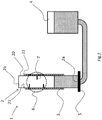
- FIG. 2 shows the same heating unit 1 as shown in figure 1 together with liquid level controlling container 4 as a sectional view.
- the heating unit 1 comprises a heating element 3 arranged on the outer surface 22 of the wall 20 of the fluid container 2.
- the heating element 3 is preferably brazed to the fluid container 2 such that a firm connection is formed.
- the fluid container 2 is in a fluid communication with a liquid level controlling container 4 for controlling the liquid level in the fluid container 2. Liquid is added to the liquid level controlling container 4 wherefrom it goes through an inlet in the bottom 5 of the fluid container 2 and enters to the fluid container 2. When the liquid in the fluid container 2 boils steam is generated and the generated steam exits the fluid container 2 via outlet 2b on top of the fluid container 2.
- Liquid droplets that are present in the steam exiting the fluid container 2 are removed from the steam with a drop separator 6 comprising restraints 7.
- the restraints 7 are plate-like elements arranged in the inner surface 21 of the wall 20 of the fluid container 2.
- the restraints 7 may also be of another form, for example a single piece drop separator 6 that is formed by bending a plate such that multiple different restraints 7 are formed in the separator 6 which can be attached to the fluid container 2 by hanging it in the outlet 2b or by attaching it in some other way.
- 3 restraints 7 are arranged but the amount, size and shape may vary according to the shape and size of the fluid container 2.
- an additional inlet in the fluid container 2 for adding for example decalcifying liquid to the fluid container 2 may be in some suitable place in between the fluid container 2 and the liquid level controlling container 4.
- the heating device may comprise multiple heating units 1 arranged in series and communicating with the liquid level controlling container 4.
- the heating element 3 can be electrically heated or it can be heated with fuel.
Landscapes
- Engineering & Computer Science (AREA)
- Physics & Mathematics (AREA)
- Thermal Sciences (AREA)
- Mechanical Engineering (AREA)
- General Engineering & Computer Science (AREA)
- Life Sciences & Earth Sciences (AREA)
- Sustainable Development (AREA)
- Sustainable Energy (AREA)
- Chemical & Material Sciences (AREA)
- Combustion & Propulsion (AREA)
- Cookers (AREA)
Claims (15)
- Heizeinheit (1) zum Erzeugen von Dampf aus einer Flüssigkeit und zum Erwärmen von Gas, wobei die Heizeinheit (1) Folgendes umfasst:- einen Fluidbehälter (2) mit einer Wand (20), wobei die Wand (20) eine Innenfläche (21) und eine Außenfläche (22) umfasst, und- ein Heizelement (3), das mit der Wand (20) des Fluidbehälters (2) in Kontakt ist, das Heizelement (3) ist derart an der Wand (20) angeordnet, dass eine Flüssigkeit, die im Fluidbehälter (2) angeordnet ist, via die Innenfläche (21) der Wand (20) indirekt erwärmt wird, derart, dass aus der Flüssigkeit im Fluidbehälter (2) Dampf erzeugt wird, dadurch gekennzeichnet, dass das Heizelement (3) angeordnet ist, Gas auf der Seite der Außenfläche (22) der Wand (20) des Fluidbehälters (2) zu erwärmen.
- Heizeinheit (1) nach Anspruch 1, wobei:- das Heizelement (3) derart an der Wand (20) angeordnet ist, dass das Heizelement (3) zum direkten Erwärmen von Gas außerhalb des Fluidbehälters (2) mindestens einen Teil der Außenfläche (22) der Wand (20) bildet; oder- das Heizelement (3) zum indirekten Erwärmen von Gas an der Außenfläche des Fluidbehälters (2) in der Wand (20) des Fluidbehälters (2) zwischen der Innenfläche (21) und der Außenfläche (22) angeordnet ist.
- Heizeinheit (1) nach einem der vorhergehenden Ansprüche, wobei die Außenfläche (22) der Wand (20) des Fluidbehälters (2) Rippen umfasst, die von der Wand (20) vorstehen.
- Heizeinheit (1) nach Anspruch 3, wobei das Heizelement (3) mindestens einen Teil der Rippen bildet.
- Heizeinheit (1) nach einem der vorhergehenden Ansprüche, wobei der Fluidbehälter (2) einen Einlass (2a) zum Eintreten der Flüssigkeit in den Fluidbehälter (2) und einen Auslass (2b) zum Austreten von Dampf aus dem Fluidbehälter (2) umfasst.
- Heizeinheit (1) nach Anspruch 5, wobei der Fluidbehälter (2) einen Boden und der Einlass (2a) im Boden oder in der Wand (20) in der Nähe des Bodens angeordnet ist, und eine Oberseite und der Auslass (2b) in der Oberseite oder in der Nähe der Oberseite angeordnet ist, umfasst.
- Heizeinheit (1) nach einem der vorhergehenden Ansprüche, wobei das Heizelement (3) eine Spiralstruktur ist, die um den Fluidbehälter (2) angeordnet ist.
- Heizeinheit (1) nach einem der vorhergehenden Ansprüche, wobei die Heizeinheit (1) zum Verhindern, dass Flüssigkeitstropfen aus dem Fluidbehälter (2) austreten, ferner einen Tropfenabscheider (6) umfasst.
- Heizeinheit (1) nach einem der vorhergehenden Ansprüche, wobei der Fluidbehälter (2) und das Heizelement (3) derart fest miteinander verbunden sind, dass das Heizelement (3) ein integraler Teil des Fluidbehälters (2) ist.
- Heizvorrichtung, die eine Heizeinheit (1) nach Anspruch 1 umfasst, wobei der Fluidbehälter (2) einen Einlass (2a) zum Eintreten der Flüssigkeit in den Fluidbehälter (2) und einen Auslass (2b) zum Austreten von Dampf aus dem Fluidbehälter (2) umfasst und die Heizvorrichtung ferner Folgendes umfasst:- eine Flüssigkeitsverbindung zum Zuführen von Flüssigkeit durch den Einlass (2a) zum Fluidbehälter (2) und- einen Lüfter zum Leiten von Gas zu Heizeinheit (1).
- Heizvorrichtung nach Anspruch 10, wobei die Heizvorrichtung ferner zum Steuern eines Flüssigkeitsvolumens im Fluidbehälter (2) nach dem Prinzip kommunizierender Gefäße einen Flüssigkeitsstandsteuerbehälter (4) in einer Fluidkommunikation mit dem Fluidbehälter (2) umfasst.
- Verfahren zum Erzeugen von Dampf aus einer Flüssigkeit und zum Erwärmen von Gas in einer Heizeinheit (1) nach Anspruch 1, dadurch gekennzeichnet, dass das Verfahren die folgenden Schritte umfasst:a) Zuführen von Flüssigkeit zum Fluidbehälter (2),b) Zuführen von Gas zur Heizeinheit (1) undc) Betreiben des Heizelements (3) derart, dass aus der Flüssigkeit im Fluidbehälter (2) Dampf erzeugt wird und/oder dass außerhalb der Heizeinheit (1) Gas erwärmt wird.
- Verfahren nach Anspruch 12, wobei die Schritte a) und b) zum gleichzeitigen Erzeugen von Dampf und Erwärmen von Gas gleichzeitig ausgeführt werden.
- Verfahren nach Anspruch 12, wobei die Schritte a) und b) separat oder in Folge ausgeführt werden.
- Verfahren nach einem der Ansprüche 12-14, wobei das Verfahren ferner die folgenden Schritte umfasst:d) Bereitstellen eines Flüssigkeitsstandsteuerbehälters (4) in einer Fluidkommunikation mit dem Fluidbehälter (2) unde) Steuern eines Flüssigkeitsstands im Fluidbehälter (2) nach dem Prinzip kommunizierender Gefäße.
Applications Claiming Priority (1)
| Application Number | Priority Date | Filing Date | Title |
|---|---|---|---|
| FI20145074A FI125460B (en) | 2014-01-27 | 2014-01-27 | Heating unit, heating device and method for generating vapor from liquid and heating gas in heating unit |
Publications (2)
| Publication Number | Publication Date |
|---|---|
| EP2899460A1 EP2899460A1 (de) | 2015-07-29 |
| EP2899460B1 true EP2899460B1 (de) | 2020-10-21 |
Family
ID=52396549
Family Applications (1)
| Application Number | Title | Priority Date | Filing Date |
|---|---|---|---|
| EP15152434.5A Active EP2899460B1 (de) | 2014-01-27 | 2015-01-26 | Heizeinheit, Heizvorrichtung und Verfahren zur Dampferzeugung aus einer Flüssigkeit und Erhitzen von Gas in einer Heizeinheit |
Country Status (2)
| Country | Link |
|---|---|
| EP (1) | EP2899460B1 (de) |
| FI (1) | FI125460B (de) |
Family Cites Families (2)
| Publication number | Priority date | Publication date | Assignee | Title |
|---|---|---|---|---|
| JP3694922B2 (ja) * | 1995-06-22 | 2005-09-14 | 松下電器産業株式会社 | 蒸気発生装置 |
| JP2000266302A (ja) * | 1999-03-17 | 2000-09-29 | Shokuhin Sangyo Denshi Riyo Gijutsu Kenkyu Kumiai | 蒸気発生器 |
-
2014
- 2014-01-27 FI FI20145074A patent/FI125460B/en active IP Right Grant
-
2015
- 2015-01-26 EP EP15152434.5A patent/EP2899460B1/de active Active
Also Published As
| Publication number | Publication date |
|---|---|
| FI20145074A7 (fi) | 2015-07-28 |
| FI125460B (en) | 2015-10-15 |
| EP2899460A1 (de) | 2015-07-29 |
Similar Documents
| Publication | Publication Date | Title |
|---|---|---|
| CN102132101B (zh) | 蒸汽发生装置以及加热烹饪器 | |
| EP3553392B1 (de) | Kochgerät | |
| EP2360432B1 (de) | Dampferzeuger | |
| CN102595985B (zh) | 加热器 | |
| RU2531415C2 (ru) | Варочное устройство | |
| EP1654931B1 (de) | Dampferzeuger für einen Dampfgarofen | |
| CN106923653B (zh) | 蒸汽烹饪装置 | |
| RU2012127883A (ru) | Устройство для нагрева потока | |
| KR101947778B1 (ko) | 가습장치 | |
| KR101284544B1 (ko) | 중화렌지 열을 이용한 온수발생장치 | |
| JP6716232B2 (ja) | 蒸気発生装置 | |
| KR20100054148A (ko) | 물 예열 섹션을 갖는 보일러 | |
| WO2008125947A1 (en) | Steam generator | |
| FI125460B (en) | Heating unit, heating device and method for generating vapor from liquid and heating gas in heating unit | |
| TW201705885A (zh) | 延時滴管式蒸汽發生器和基於該發生器的食物製作設備 | |
| WO2019039970A2 (ru) | Электрический парогенератор (варианты) | |
| JP7090321B2 (ja) | 食材茹で機 | |
| JP5722918B2 (ja) | 急速湯沸かし器およびその湯沸かし器を備える家庭電化製品 | |
| EP3903042B1 (de) | Ofen mit dampfgarfunktion | |
| JP3894066B2 (ja) | 蒸気発生装置及び蒸気発生装置を備えた加熱調理装置 | |
| KR200493847Y1 (ko) | 스팀 생성유닛 | |
| EP2371250B1 (de) | Vorrichtung zum Kochen von Nahrungsmitteln | |
| EP4394257A1 (de) | Ofen mit dampfkochfunktion | |
| JP2007315647A (ja) | 流体加熱器及び流体加熱器の制御装置 | |
| RU179399U1 (ru) | Электрическая печь для сауны Вахова В.И. |
Legal Events
| Date | Code | Title | Description |
|---|---|---|---|
| PUAI | Public reference made under article 153(3) epc to a published international application that has entered the european phase |
Free format text: ORIGINAL CODE: 0009012 |
|
| 17P | Request for examination filed |
Effective date: 20150126 |
|
| AK | Designated contracting states |
Kind code of ref document: A1 Designated state(s): AL AT BE BG CH CY CZ DE DK EE ES FI FR GB GR HR HU IE IS IT LI LT LU LV MC MK MT NL NO PL PT RO RS SE SI SK SM TR |
|
| AX | Request for extension of the european patent |
Extension state: BA ME |
|
| 17P | Request for examination filed |
Effective date: 20160129 |
|
| RBV | Designated contracting states (corrected) |
Designated state(s): AL AT BE BG CH CY CZ DE DK EE ES FI FR GB GR HR HU IE IS IT LI LT LU LV MC MK MT NL NO PL PT RO RS SE SI SK SM TR |
|
| GRAP | Despatch of communication of intention to grant a patent |
Free format text: ORIGINAL CODE: EPIDOSNIGR1 |
|
| STAA | Information on the status of an ep patent application or granted ep patent |
Free format text: STATUS: GRANT OF PATENT IS INTENDED |
|
| RIC1 | Information provided on ipc code assigned before grant |
Ipc: F22B 1/28 20060101AFI20200522BHEP |
|
| INTG | Intention to grant announced |
Effective date: 20200622 |
|
| GRAS | Grant fee paid |
Free format text: ORIGINAL CODE: EPIDOSNIGR3 |
|
| GRAA | (expected) grant |
Free format text: ORIGINAL CODE: 0009210 |
|
| STAA | Information on the status of an ep patent application or granted ep patent |
Free format text: STATUS: THE PATENT HAS BEEN GRANTED |
|
| AK | Designated contracting states |
Kind code of ref document: B1 Designated state(s): AL AT BE BG CH CY CZ DE DK EE ES FI FR GB GR HR HU IE IS IT LI LT LU LV MC MK MT NL NO PL PT RO RS SE SI SK SM TR |
|
| REG | Reference to a national code |
Ref country code: GB Ref legal event code: FG4D |
|
| REG | Reference to a national code |
Ref country code: CH Ref legal event code: EP |
|
| REG | Reference to a national code |
Ref country code: IE Ref legal event code: FG4D |
|
| REG | Reference to a national code |
Ref country code: DE Ref legal event code: R096 Ref document number: 602015060675 Country of ref document: DE |
|
| REG | Reference to a national code |
Ref country code: AT Ref legal event code: REF Ref document number: 1326199 Country of ref document: AT Kind code of ref document: T Effective date: 20201115 |
|
| REG | Reference to a national code |
Ref country code: CH Ref legal event code: NV Representative=s name: VALIPAT S.A. C/O BOVARD SA NEUCHATEL, CH |
|
| REG | Reference to a national code |
Ref country code: AT Ref legal event code: MK05 Ref document number: 1326199 Country of ref document: AT Kind code of ref document: T Effective date: 20201021 |
|
| REG | Reference to a national code |
Ref country code: NL Ref legal event code: MP Effective date: 20201021 |
|
| PG25 | Lapsed in a contracting state [announced via postgrant information from national office to epo] |
Ref country code: GR Free format text: LAPSE BECAUSE OF FAILURE TO SUBMIT A TRANSLATION OF THE DESCRIPTION OR TO PAY THE FEE WITHIN THE PRESCRIBED TIME-LIMIT Effective date: 20210122 Ref country code: RS Free format text: LAPSE BECAUSE OF FAILURE TO SUBMIT A TRANSLATION OF THE DESCRIPTION OR TO PAY THE FEE WITHIN THE PRESCRIBED TIME-LIMIT Effective date: 20201021 Ref country code: FI Free format text: LAPSE BECAUSE OF FAILURE TO SUBMIT A TRANSLATION OF THE DESCRIPTION OR TO PAY THE FEE WITHIN THE PRESCRIBED TIME-LIMIT Effective date: 20201021 Ref country code: PT Free format text: LAPSE BECAUSE OF FAILURE TO SUBMIT A TRANSLATION OF THE DESCRIPTION OR TO PAY THE FEE WITHIN THE PRESCRIBED TIME-LIMIT Effective date: 20210222 Ref country code: NL Free format text: LAPSE BECAUSE OF FAILURE TO SUBMIT A TRANSLATION OF THE DESCRIPTION OR TO PAY THE FEE WITHIN THE PRESCRIBED TIME-LIMIT Effective date: 20201021 Ref country code: NO Free format text: LAPSE BECAUSE OF FAILURE TO SUBMIT A TRANSLATION OF THE DESCRIPTION OR TO PAY THE FEE WITHIN THE PRESCRIBED TIME-LIMIT Effective date: 20210121 |
|
| REG | Reference to a national code |
Ref country code: LT Ref legal event code: MG4D |
|
| PG25 | Lapsed in a contracting state [announced via postgrant information from national office to epo] |
Ref country code: IS Free format text: LAPSE BECAUSE OF FAILURE TO SUBMIT A TRANSLATION OF THE DESCRIPTION OR TO PAY THE FEE WITHIN THE PRESCRIBED TIME-LIMIT Effective date: 20210221 Ref country code: LV Free format text: LAPSE BECAUSE OF FAILURE TO SUBMIT A TRANSLATION OF THE DESCRIPTION OR TO PAY THE FEE WITHIN THE PRESCRIBED TIME-LIMIT Effective date: 20201021 Ref country code: SE Free format text: LAPSE BECAUSE OF FAILURE TO SUBMIT A TRANSLATION OF THE DESCRIPTION OR TO PAY THE FEE WITHIN THE PRESCRIBED TIME-LIMIT Effective date: 20201021 Ref country code: AT Free format text: LAPSE BECAUSE OF FAILURE TO SUBMIT A TRANSLATION OF THE DESCRIPTION OR TO PAY THE FEE WITHIN THE PRESCRIBED TIME-LIMIT Effective date: 20201021 Ref country code: ES Free format text: LAPSE BECAUSE OF FAILURE TO SUBMIT A TRANSLATION OF THE DESCRIPTION OR TO PAY THE FEE WITHIN THE PRESCRIBED TIME-LIMIT Effective date: 20201021 Ref country code: BG Free format text: LAPSE BECAUSE OF FAILURE TO SUBMIT A TRANSLATION OF THE DESCRIPTION OR TO PAY THE FEE WITHIN THE PRESCRIBED TIME-LIMIT Effective date: 20210121 |
|
| PG25 | Lapsed in a contracting state [announced via postgrant information from national office to epo] |
Ref country code: HR Free format text: LAPSE BECAUSE OF FAILURE TO SUBMIT A TRANSLATION OF THE DESCRIPTION OR TO PAY THE FEE WITHIN THE PRESCRIBED TIME-LIMIT Effective date: 20201021 |
|
| REG | Reference to a national code |
Ref country code: DE Ref legal event code: R097 Ref document number: 602015060675 Country of ref document: DE |
|
| PG25 | Lapsed in a contracting state [announced via postgrant information from national office to epo] |
Ref country code: SK Free format text: LAPSE BECAUSE OF FAILURE TO SUBMIT A TRANSLATION OF THE DESCRIPTION OR TO PAY THE FEE WITHIN THE PRESCRIBED TIME-LIMIT Effective date: 20201021 Ref country code: RO Free format text: LAPSE BECAUSE OF FAILURE TO SUBMIT A TRANSLATION OF THE DESCRIPTION OR TO PAY THE FEE WITHIN THE PRESCRIBED TIME-LIMIT Effective date: 20201021 Ref country code: LT Free format text: LAPSE BECAUSE OF FAILURE TO SUBMIT A TRANSLATION OF THE DESCRIPTION OR TO PAY THE FEE WITHIN THE PRESCRIBED TIME-LIMIT Effective date: 20201021 Ref country code: SM Free format text: LAPSE BECAUSE OF FAILURE TO SUBMIT A TRANSLATION OF THE DESCRIPTION OR TO PAY THE FEE WITHIN THE PRESCRIBED TIME-LIMIT Effective date: 20201021 Ref country code: EE Free format text: LAPSE BECAUSE OF FAILURE TO SUBMIT A TRANSLATION OF THE DESCRIPTION OR TO PAY THE FEE WITHIN THE PRESCRIBED TIME-LIMIT Effective date: 20201021 Ref country code: CZ Free format text: LAPSE BECAUSE OF FAILURE TO SUBMIT A TRANSLATION OF THE DESCRIPTION OR TO PAY THE FEE WITHIN THE PRESCRIBED TIME-LIMIT Effective date: 20201021 |
|
| PLBE | No opposition filed within time limit |
Free format text: ORIGINAL CODE: 0009261 |
|
| STAA | Information on the status of an ep patent application or granted ep patent |
Free format text: STATUS: NO OPPOSITION FILED WITHIN TIME LIMIT |
|
| PG25 | Lapsed in a contracting state [announced via postgrant information from national office to epo] |
Ref country code: DK Free format text: LAPSE BECAUSE OF FAILURE TO SUBMIT A TRANSLATION OF THE DESCRIPTION OR TO PAY THE FEE WITHIN THE PRESCRIBED TIME-LIMIT Effective date: 20201021 Ref country code: MC Free format text: LAPSE BECAUSE OF FAILURE TO SUBMIT A TRANSLATION OF THE DESCRIPTION OR TO PAY THE FEE WITHIN THE PRESCRIBED TIME-LIMIT Effective date: 20201021 |
|
| 26N | No opposition filed |
Effective date: 20210722 |
|
| GBPC | Gb: european patent ceased through non-payment of renewal fee |
Effective date: 20210126 |
|
| PG25 | Lapsed in a contracting state [announced via postgrant information from national office to epo] |
Ref country code: LU Free format text: LAPSE BECAUSE OF NON-PAYMENT OF DUE FEES Effective date: 20210126 |
|
| REG | Reference to a national code |
Ref country code: BE Ref legal event code: MM Effective date: 20210131 |
|
| PG25 | Lapsed in a contracting state [announced via postgrant information from national office to epo] |
Ref country code: AL Free format text: LAPSE BECAUSE OF FAILURE TO SUBMIT A TRANSLATION OF THE DESCRIPTION OR TO PAY THE FEE WITHIN THE PRESCRIBED TIME-LIMIT Effective date: 20201021 |
|
| PG25 | Lapsed in a contracting state [announced via postgrant information from national office to epo] |
Ref country code: GB Free format text: LAPSE BECAUSE OF NON-PAYMENT OF DUE FEES Effective date: 20210126 Ref country code: SI Free format text: LAPSE BECAUSE OF FAILURE TO SUBMIT A TRANSLATION OF THE DESCRIPTION OR TO PAY THE FEE WITHIN THE PRESCRIBED TIME-LIMIT Effective date: 20201021 |
|
| PG25 | Lapsed in a contracting state [announced via postgrant information from national office to epo] |
Ref country code: IE Free format text: LAPSE BECAUSE OF NON-PAYMENT OF DUE FEES Effective date: 20210126 |
|
| PG25 | Lapsed in a contracting state [announced via postgrant information from national office to epo] |
Ref country code: IS Free format text: LAPSE BECAUSE OF FAILURE TO SUBMIT A TRANSLATION OF THE DESCRIPTION OR TO PAY THE FEE WITHIN THE PRESCRIBED TIME-LIMIT Effective date: 20210221 |
|
| PG25 | Lapsed in a contracting state [announced via postgrant information from national office to epo] |
Ref country code: BE Free format text: LAPSE BECAUSE OF NON-PAYMENT OF DUE FEES Effective date: 20210131 |
|
| PG25 | Lapsed in a contracting state [announced via postgrant information from national office to epo] |
Ref country code: HU Free format text: LAPSE BECAUSE OF FAILURE TO SUBMIT A TRANSLATION OF THE DESCRIPTION OR TO PAY THE FEE WITHIN THE PRESCRIBED TIME-LIMIT; INVALID AB INITIO Effective date: 20150126 |
|
| PG25 | Lapsed in a contracting state [announced via postgrant information from national office to epo] |
Ref country code: CY Free format text: LAPSE BECAUSE OF FAILURE TO SUBMIT A TRANSLATION OF THE DESCRIPTION OR TO PAY THE FEE WITHIN THE PRESCRIBED TIME-LIMIT Effective date: 20201021 |
|
| PG25 | Lapsed in a contracting state [announced via postgrant information from national office to epo] |
Ref country code: MK Free format text: LAPSE BECAUSE OF FAILURE TO SUBMIT A TRANSLATION OF THE DESCRIPTION OR TO PAY THE FEE WITHIN THE PRESCRIBED TIME-LIMIT Effective date: 20201021 |
|
| PG25 | Lapsed in a contracting state [announced via postgrant information from national office to epo] |
Ref country code: MT Free format text: LAPSE BECAUSE OF FAILURE TO SUBMIT A TRANSLATION OF THE DESCRIPTION OR TO PAY THE FEE WITHIN THE PRESCRIBED TIME-LIMIT Effective date: 20201021 |
|
| REG | Reference to a national code |
Ref country code: CH Ref legal event code: U11 Free format text: ST27 STATUS EVENT CODE: U-0-0-U10-U11 (AS PROVIDED BY THE NATIONAL OFFICE) Effective date: 20260201 |
|
| PGFP | Annual fee paid to national office [announced via postgrant information from national office to epo] |
Ref country code: DE Payment date: 20260122 Year of fee payment: 12 |
|
| PGFP | Annual fee paid to national office [announced via postgrant information from national office to epo] |
Ref country code: IT Payment date: 20260127 Year of fee payment: 12 |
|
| PGFP | Annual fee paid to national office [announced via postgrant information from national office to epo] |
Ref country code: FR Payment date: 20260120 Year of fee payment: 12 |
|
| PGFP | Annual fee paid to national office [announced via postgrant information from national office to epo] |
Ref country code: TR Payment date: 20260112 Year of fee payment: 12 |
|
| PGFP | Annual fee paid to national office [announced via postgrant information from national office to epo] |
Ref country code: CH Payment date: 20260201 Year of fee payment: 12 |
|
| PGFP | Annual fee paid to national office [announced via postgrant information from national office to epo] |
Ref country code: PL Payment date: 20260102 Year of fee payment: 12 |